Abstract
In this paper preliminary results of the numerical assessment of PAT erosion, caused by the impingement of solid particles in the water flow, are provided and discussed. A CFD model was developed by the Università degli Studi di Napoli Federico II to investigate the fluid dynamics of a PAT and coupled with the in-house E-CODE developed by the Politecnico di Milano for wear estimation. The erosion simulations were performed to assess the wear of PAT components, namely inlet, impeller, volute and outlet pipe, for abrasive particles with different size, aiming at estimating the relation between the fluid dynamics of the slurry flow and the development of the erosion process.
1. Introduction
The use of Pumps As Turbines (PATs) in hydraulic systems allows to couple the pressure regulation with the hydropower generation. PATs are pumps running in reverse mode by using the motor as an electrical generator. Their application is effective in both water supply systems [1,2,3] and wastewater treatment plants [4,5].
Advantages related to the use of PATs derive from the large availability of pumps in the market, together with low investment and maintenance costs, with both ease of installation and short payback periods [6,7].
On the other hand, one of the main limitations in the use of PATs arises from the little knowledge about their performance and their internal behavior in both steady and transient conditions, because the characteristic curves are rarely provided by manufactures. Several literature studies proposed various methods to overcome such limitation, relying on either experimental testing [8,9,10] or numerical simulations [11,12,13].
Several models were developed based on the Computational Fluid Dynamics (CFD) technique, which couples the Reynolds Averaged-Navier Stokes (RANS) equations with turbulence models. Avoiding the significant time-demand and the expensive costs related to the experimental researches, CFD models allow both the performance prediction [11,12,13] and the flow field calculation, allowing the investigation of secondary flows, internal head losses, generated force and torque and cavitation [14]. Furthermore, the optimization of the performance of the machine is also possible by simulating different geometrical configurations [15,16]. Nevertheless, the use of CFD definitely requires proper calibration and validation procedures through experimental data [17].
In the field of the study of the internal behavior of a PAT, the assessment of the mechanical wear caused by the impingement of solid particles is an interesting yet unresolved issue. In the literature, several CFD applications were devoted to the erosion assessment in pumps. Among them, Wang et al. [18] applied the CFX4 finite volume algorithm to numerically estimate the erosion in a centrifugal pump due to slurry jet flows. Kruger et al. [19] simulated the quartz sand impingement in a centrifugal pump, observing significant erosion areas along the blade and the impeller trailing edge, depending on the particle impingement angle and solid concentration. Lopez et al. [20] investigated how the erosion predictions in a pump were affected by numerical settings and parameters of the CFD-based wear estimation model. All the considered model formulations yielded the same locations of the maximum wear areas, placed around the blades, but different predictions in terms of amount of removed material. Pagalthivarthi et al. [21] numerically analyzed the erosion wear in centrifugal slurry pumps, observing the increase of the wear rate at reducing the casing width. The authors performed a sensitivity analysis to evaluate the dependency of erosion from geometric parameters, namely the tongue curvature, the slope of the discharge pipe and the casing width, also observing that the pump rotational speed strongly affects the erosion intensity.
Nevertheless, up to the authors’ knowledge, no numerical application is available to assess the mechanical wear in PATs, occurring when solid particles impinge on their internal surfaces, for instance when the device is used in wastewater treatment plants. In this study, a CFD model implemented by the Università di Napoli Federico II, used to simulate the performances of a single-stage horizontal axis centrifugal PAT, was coupled with the in-house numerical E-CODE, developed by the Politecnico di Milano, to estimate the wear process and locate the erosion hotspots. To this aim, several simulations have been carried on, in order to investigate the consistency of the numerical predictions with respect to the number of grid cells and number of injected particles.
2. Materials and Methods
2.1. CFD Modelling of a Centrifugal Single-Stage PAT
A CFD model, developed by the Università degli Studi di Napoli Federico II [22], was applied to assess the fluid dynamic field. The model was implemented by using the ANSYS® framework, from a 3D scanning procedure of an experimentally tested PAT with a 6 blade impeller of D = 0.189 m diameter. Two connection pipes at inlet and outlet were also integrated to properly set the boundary conditions. A structured hexahedral mesh was generated with the ANSYS® ICEM CFD™ tool for connection pipes, whereas, due to their complex configuration, an unstructured tetrahedral mesh was applied for the impeller and volute components (Figure 1). Specific refinements were also introduced around both the volute tongue region and the impeller blades, aimed at increasing the mesh regularity and interface between impeller and volute. Three meshes with increasing resolution were generated, in order to assess the dependence of the numerical solution on the grid. In the following Table 1, the number of elements of each PAT zone is summarized for the three meshes.
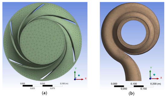
Figure 1.
Representation of 1.2 M mesh level for (a) impeller front; (b) volute front.

Table 1.
Number of elements for each mesh resolution level.
The ANSYS® Fluent™ code [23] was employed for fluid dynamics simulations, setting the standard k-ε turbulence model, with scalable wall functions for the near-wall treatment. Second-order upwind spatial discretization was also applied to all solved variables, and low relaxation factors were used to limit instabilities during the convergence procedure. Three planar interfaces were introduced to simulate the interaction between inlet pipe-volute, volute-impeller and impeller-outlet pipe, respectively. As boundary conditions at inlet and outlet, a uniform velocity distribution and a static pressure value were set, respectively.
The model validation was done, by applying a two-steps computational procedure, to simulate:
- Steady-state conditions, by applying the Moving Reference Frame (MRF) approach, able to simulate the volute-impeller interaction through a frozen-rotor interface, as a function of a fixed angular deviation of the impeller;
- Unsteady-state conditions, applied once the convergence of the steady-state mode was achieved. The velocity and pressure fields from the steady-state mode were applied to initialize the simulations, by reproducing the relative motion between impeller and volute through the Sliding Mesh (MS) technique. The time step duration was evaluated so that a complete impeller revolution was performed in 150 time-steps and not less than 5 complete impeller revolutions were simulated, useful to achieve the periodicity of flow parameters.
Calibration of the CFD model was performed, as a function of the head drop generated by the PAT, estimated as difference between the pressure at inlet and outlet, whereas the overall generated power Pt was assessed as a function of the torque on the impeller, estimated from the integration of the pressure and shear stress distributions on the blades. The PAT characteristic curves for different rotational speeds N were thus derived, in the range N = 600–2900 rpm and comparison with experimental results from [10] was performed for validation.
2.2. Impact Erosion Modelling
The procedure for estimating the erosion of the PAT was developed starting from the two-stage strategy usually employed in CFD-based wear prediction studies. First, the slurry flow was simulated by an Eulerian-Lagrangian model [24], in which the fluid flow is represented in an Eulerian, cell based framework, whilst the solid phase is modeled by following a certain number of particle trajectories. Afterwards, an erosion model was employed to estimate the loss of material produced by each particle-wall impingement from the impact velocity, the impact angle, and other parameters involved in the wear process [25]. The low solid content considered in this work (i.e., 1‰ by volume) enabled the hypothesis of one-way coupling regime, which is the assumption that the liquid flow is not affected by the particles [26]. Therefore, the Lagrangian tracking calculations were performed after the single-phase simulation by solving the following equation of motion for each particle:
where t is the Lagrangian time, vp is the instantaneous velocity vector of the particle, mp is the particle mass, and Fd, Fvm, and Fp are the drag, virtual mass, and pressure gradient forces acting on a particle, respectively. The last three terms were calculated as detailed in the Fluent User’s Guide [23], assuming spherical particles and employing the default settings. The discrete random walk model was also activated to account for particle turbulent dispersion. Other forces, such as gravity, lift, and history force, were neglected because previous studies [27] and theoretical considerations [26] suggested their minor importance for the flows addressed in this study.
In order to achieve simulation results within acceptable time limits, the Lagrangian tracking was solved as steady state and each particle is attributed a fixed mass flux. The fluid flow field used to solve Equation (1) was that of the single-phase MRF simulation previously illustrated, involving an outer fixed zone, and an inner zone moving with the impeller. Since the velocity vectors referred to different coordinate systems, the computed paths did not correspond to the actual trajectories of the particles. Nevertheless, this approach appeared a reasonable way to estimate the particles’ fluid dynamic characteristics at the impact stage, which are required as input in erosion calculation.
The wear predictions were performed using the in-house E-CODE developed within the research group of Politecnico di Milano. The solution strategy of the E-CODE was well described in [27], and it relies on the application of an erosion model to each particle-wall collision and a topological triangulation of the different components of the simulated geometry. In this work, the Oka et al. [28,29] erosion model was employed, with all constants other than density and Vickers hardness set as in [27].
2.3. Assessment of Impact Erosion of PAT through the E-CODE
The E-CODE was applied to assess the impact erosion at the Best Efficiency Point (BEP) condition, which was experimentally observed at N = 1500 rpm rotational speed and Q = 30 L/s flow rate. Several cases were studied by varying the mesh resolutions, the number of tracked particles and the particle sizes with a total of 11 different scenarios.
Cast iron material of PAT was considered, with a ductile behavior (density 7150 kg/m3, Vickers Hardness 1.78 GPa), whereas the impinging particles were assumed of density 2650 kg/m3, spherical shape, and diameter of 0.1 mm.
Only steady state conditions (MRF approach introduced in Par. 2.1) were used for the simulations.
For each scenario and each PAT component, the following parameters were estimated:
- the Integral Erosion Ratio (IER), intended as the ratio between the wear mass flow rate and the inlet solid mass flow;
- the frequency distributions of impact velocities and impact angles;
- the Penetration Rate (PR) distributions, useful to assess the local erosion velocity.
3. Results and Discussion
At first, it was necessary to assess the numerical consistency of the wear estimates with respect to the number of tracked particles. In fact, each computational particle did not represent a physical particle but a group of particles corresponding to a certain solid mass flux, thereby making it necessary to ensure that a statistically representative set of particle impingements was obtained. This was achieved by increasing the number of particles until the wear estimates reached a plateau.
The finest mesh (2.5 M) was considered with a number of impinging particles ranging between 1000 and 25,000. The results, summarized in the following Table 2, showed a weak dependence of the IER on the total number of particles and the results change very slightly when the total number of particles is higher than 10,000. The intensity of the wear was higher for the outlet pipe and the volute, while decreases for the impeller and is the lowest for the inlet pipe.
Table 2.
Integral Erosion Ratio (IER) estimation at varying the Number of Particles (NP) (2.5 M mesh resolution, MRF approach).
Simulations have shown that some particles went on impinging the volute without being able to leave the domain. At present, it is not clear whether this behavior was physical or simply arising from numerical issues, anyway it caused huge calculation time and memory consumption when running the E-CODE. Thus, particles impinging more than 500 times the same PAT component were removed from the erosion calculation to keep the computational burden within acceptable limits.
For the impeller component, the frequency distribution of the particle impact velocities, normalized with the number of tracked particles, resulted significantly comparable for the three number of particles (Figure 2a). The same held for the impact angle (Figure 2b), further indicating that 10,000 particles allowed consistent wear estimates. It was also observed that most impacts occurred for velocities of about 1.8 m/s, whereas a decreasing trend was determined for lower and higher velocities. Similarly, the frequency distribution of the angle of impact presented a peak at about 82°, with a rapid decrease for lower and higher values.
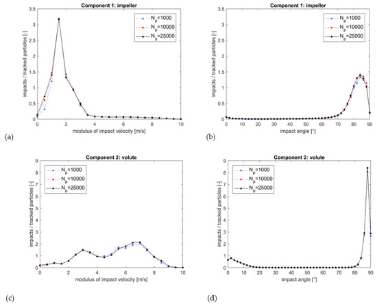
Figure 2.
Frequency distribution of particle impact velocity and impact angle for the impeller (a,b) and the volute (c,d).
The frequency distribution of the particle impact velocity on the volute presented two relative maxima at about 3 and 7 m/s, with a greater number of impacts for the higher velocity (Figure 2c). Such values depend on the hydro-mechanical design of the machine and are in accordance with the velocity distribution of the fluid dynamic field of the volute. The distribution of impact angles also presented two relative maxima. Nevertheless, as observed for the impeller, impact angles between 80° and 90° were the most frequent (Figure 2d). Also in this case, the distribution seemed substantially independent from the number of particles.
By analyzing the distribution of the penetration rate on the PAT, several susceptible zones were identified in the volute, the impeller, and the outlet pipe. The volute inner part, around the impeller shroud, resulted the most eroded area. Lower penetration rates were observed within the impeller, with greater concentration at the blade outlets. This result is important for the evaluation of the decrease of the efficiency of the machine due to the wear, since the geometry of the blades is strongly related to the performance of the machine [13]. Concerning the inlet and outlet pipes, loss of material was observed around the outlet pipe, due to the vorticity of the outlet flux, whereas negligible effects involved the inlet pipe (Figure 3).

Figure 3.
Penetration rate for PAT parts (2.5 M mesh resolution; NP = 25,000).
Similar simulations have been carried out with the coarse resolution mesh (1.2 M mesh resolution) yielding wear estimates about 20% higher for the volute, and very similar results for the other components. Indeed, such a level of discrepancy is much lower than that inherent in CFD-based erosion prediction methods [27], nevertheless additional analyses have been planned to attain a more accurate solution. The simulations have not been carried out with the coarsest (0.9 M) mesh. But, since the obtained results were similar for the 2.4 M and the 1.2 M meshes, no significant discrepancies would be expected with the 0.9 M mesh.
4. Conclusions
Preliminary results of the numerical assessment of impact erosion in a centrifugal PAT were provided. Two mesh resolutions were employed, observing a deviation between the wear estimates of about 20% for one component. For both meshes, tracking 10,000 particles allowed attaining consistent erosion predictions.
The higher erosion was found in the volute and in the outlet pipe, while the erosion rate of the impeller was slightly lower. The evaluation of the erosion of the impeller and the blades is crucial for the evaluation of the decreasing of efficiency of the machine with the wear. The erosion of the inlet pipe could be considered negligible. The frequency distributions of both the velocity and impact angles have been evaluated for the volute and the impeller. In the impeller the largest number of impacts occurred for 1.8 m/s velocity and 82° impact angle. The distributions for the volute, instead, presented two relative maximum, at about 3 and 7 m/s and about 2° and 88° impact angle.
Next steps will be devoted to both increase the mesh resolution and extend the simulations to transient conditions, with the aim of assessing the wear formation in dynamic operative conditions of the PAT. Simulations at different flow rate values and rotational speeds will also allow both extending the achieved results to wide operative ranges and assessing the erosion dependancy from the flowing rate and the mechanical properties of the PAT.
Author Contributions
A.C., O.F. and S.M. conceived the investigation of the treated topic; F.P. and M.G. performed the experiments on the investigated PAT and implemented the numerical CFD model; G.M. and S.M. implemented the E-CODE erosion model and its application to the investigated PAT; O.F., G.M. and F.P. wrote the paper.
Acknowledgments
The authors want to sincerely thank J. Fernández of the University of Oviedo (ES) and A. Senatore from Università degli Studi di Napoli Federico II for their support in developing the CFD model of the PAT. This paper was part funded by the ERDF Interreg Atlantic Area Programme 2014–2020, through the REDAWN project EAPA_198/2016.
Conflicts of Interest
The authors declare no conflict of interest.
References
- Carravetta, A.; Antipodi, L.; Golia, U.; Fecarotta, O. Energy saving in a water supply network by coupling a pump and a Pump As Turbine (PAT) in a turbopump. Water (Switzerland) 2017, 9. [Google Scholar] [CrossRef]
- Fecarotta, O.; McNabola, A. Optimal location of Pump As Turbines (PATs) in Water Distribution Networks to recovery energy and reduce leakage. Water Resour. Manag. 2017, 31, 5043–5059. [Google Scholar] [CrossRef]
- Fontana, N.; Giugni, M. Losses reduction and energy production in Water Distribution Networks. J. Water Res. PL ASCE 2012, 138, 237–244. [Google Scholar] [CrossRef]
- Power, C.; McNabola, A.; Coughlan, P. Development of an evaluation method for hydropower energy recovery in wastewater treatment plants: Case studies in Ireland and UK. Sustain. Energy Technol. Assess. 2014, 7, 166–177. [Google Scholar] [CrossRef]
- Power, C.; Coughlan, P.; McNabola, A. Microhydropower energy recovery at wastewater-treatment plants: Turbine selection and optimization. J. Energy Eng. ASCE 2017, 143. [Google Scholar] [CrossRef]
- Carravetta, A.; Fecarotta, O.; Golia, U.; La Rocca, M.; Martino, R.; Padulano, R.; Tucciarelli, T. Optimization of Osmotic Desalination Plants for Water Supply Networks. Water Resour. Manag. 2016, 30, 3965–3978. [Google Scholar] [CrossRef]
- Ozen, O.; Gulaydin, O.; Karadirek, I.E.; Muhammetoglu, A.; Muhammetoglu, H. Implementation of hydraulic modelling for site selection of pump as turbines for pressure reduction and power production in water distribution networks. Desalin. Water Treat. 2017, 86, 311–319. [Google Scholar] [CrossRef]
- Derakhshan, S.; Nourbakhsh, A. Experimental study of characteristic curves of centrifugal pumps working as turbines in different specific speeds. Exp. Therm. Fluid Sci. 2008, 32, 800–807. [Google Scholar] [CrossRef]
- Fecarotta, O.; Carravetta, A.; Ramos, H.M.; Martino, R. An improved affinity model to enhance variable operating strategy for pumps used as turbines. J. Hydraul. Res. 2016, 54, 332–341. [Google Scholar] [CrossRef]
- Pugliese, F.; De Paola, F.; Fontana, N.; Giugni, M.; Marini, G. Experimental characterization of two Pumps As Turbines for hydropower generation. Renew. Energy 2016, 99, 180–187. [Google Scholar] [CrossRef]
- Fernandez, J.; Barrio, R.; Blanco, E.; Parrondo, J.; Marcos, A. Numerical investigation of a centrifugal pump running in reverse mode. Proc. Inst. Mech. Eng. Part A J. Power Energy 2010, 224, 373–381. [Google Scholar] [CrossRef]
- Carravetta, A.; Conte, M.C.; Fecarotta, O.; Ramos, H.M. Evaluation of PAT performances by modified affinity law. Procedia Eng. 2014, 89, 581–587. [Google Scholar] [CrossRef]
- Frosina, E.; Buono, D.; Senatore, A. A performance prediction method for Pumps As Turbines (PATs) using Computational Fluid Dynamics (CFD) modeling approach. Energies 2017, 10, 1–19. [Google Scholar] [CrossRef]
- Gonzalez, J.; Fernandez Oro, J.M.; Arguelles-Diaz, K.M.; Santolaria, C. Flow analysis for a double suction centrifugal machine in the pump and turbine operation modes. Int. J. Numer. Meth. Fluids 2009, 61, 220–236. [Google Scholar] [CrossRef]
- Patel, V.A.; Jain, S.V.; Motwani, K.H.; Patel, R.N. Numerical optimization of guide vanes and reducer in pump running in turbine mode. Procedia Eng. 2013, 51, 797–802. [Google Scholar] [CrossRef]
- Yang, S.-S.; Kong, F.-Y.; Jiang, W.-M.; Qu, X.-Y. Effects of impeller trimming influencing Pump As Turbine. Comput. Fluids 2012, 67, 72–78. [Google Scholar] [CrossRef]
- Natanasabapathi, S.R.; Kshirsagar, J.T. Pump As Turbine—An Experience with CFX-5.6; Corporate Research and English Division; Kiloskar Bros. Ltd.: Pune, India, 2004. [Google Scholar]
- Wang, M.-H.; Haung, C.; Kumar, N.; Minev, P.; Luo, J.; Chiovelli, S. Computational fluid dynamics modeling and experimental study of erosion in slurry jet flows. Int. J. Comput. Fluid Dyn. 2009, 23, 155–172. [Google Scholar] [CrossRef]
- Kruger, S.; Martin, N.; Dupont, P. Assessment of wear erosion in pump impeller. In Proceedings of the 26th International Pump User Symposium, Houston, TX, USA, 15–18 March 2010; pp. 51–56. [Google Scholar]
- Lopez, A.; Stickland, M.; Dempster, W. Modeling erosion in a centrifugal pump in an Eulerial-Lagrangian frame using OpenFOAM®. Open Eng. 2015, 5, 274–279. [Google Scholar] [CrossRef]
- Pagalthivarthi, K.V.; Gupta, P.K.; Tyagi, V.; Ravi, M.R. CFD prediction of erosion wear in centrifugal slurry pumps for dilute slurry flow. J. Comput. Multiph. Flows 2011, 3, 225–246. [Google Scholar] [CrossRef]
- Pugliese, F.; De Paola, F.; Fontana, N.; Marini, G.; Fernandez, J.F. Experimental and numerical investigation of centrifugal Pumps As Turbines. In Proceedings of the 10th International Conference on Energy Efficiency in Motor Driven System, Rome, Italy, 6–7 September 2017. [Google Scholar]
- ANSYS. ANSYS Fluent User’s Guide. Available online: http://www.afs.enea.it/project/neptunius/docs/fluent/html/ug/main_pre.htm (accessed on 10 January 2018).
- Crowe, C.T.; Schwarzkopf, J.D.; Sommerfeld, M.; Tsuji, Y. Multiphase Flows with Droplets and Particles; CRC Press: Boca Raton, FL, USA, 2012. [Google Scholar]
- Parsi, M.; Najmi, K.; Najafifard, F.; Hassani, S.; McLaury, B.S.; Shirazi, S.A. A comprehensive review of solid particle erosion modeling for oil and gas wells and pipelines applications. J. Nat. Gas Sci. Eng. 2014, 21, 850–873. [Google Scholar] [CrossRef]
- Loth, E. Particles, Drops and Bubbles: Fluid Dynamics and Numerical Methods; Draft for CRC Press (Submitted for Publication). Available online: http://www.academia.edu/download/31041358/Loth_2010.pdf (accessed on 10 January 2018).
- Messa, G.V.; Malavasi, S. The effect of sub-models and parameterizations in the simulation of abrasive jet impingement tests. Wear 2017, 370, 59–72. [Google Scholar] [CrossRef]
- Oka, Y.I.; Okamura, K.; Yoshida, T. Practical estimation of erosion damage caused by solid particle impact. Part 1: Effects of impact parameters on a predictive equation. Wear 2005, 259, 95–101. [Google Scholar] [CrossRef]
- Oka, Y.I.; Yoshida, T. Practical estimation of erosion damage caused by solid particle impact. Part 2: Mechanical properties of materials directly associated with erosion damage. Wear 2005, 259, 102–109. [Google Scholar] [CrossRef]
Publisher’s Note: MDPI stays neutral with regard to jurisdictional claims in published maps and institutional affiliations. |
© 2018 by the authors. Licensee MDPI, Basel, Switzerland. This article is an open access article distributed under the terms and conditions of the Creative Commons Attribution (CC BY) license (https://creativecommons.org/licenses/by/4.0/).