Proceeding Paper

EPANET Modelling of a High Head Pumped-Storage Hydropower Facility †

by
Georgiana Dunca
1,
Diana Maria Bucur
1,
Alexandru Aldea
2,
Andrei-Mugur Georgescu
2 and
Sanda-Carmen Georgescu
1,*
1
Hydraulics, Hydraulic Machinery and Environmental Engineering Department, University “Politehnica” of Bucharest, Bucharest RO-060042, Romania
2
Hydraulics and Environmental Protection Department, Technical University of Civil Engineering of Bucharest, Bucharest RO-020396, Romania
*
Author to whom correspondence should be addressed.
Presented at the 3rd EWaS International Conference on “Insights on the Water-Energy-Food Nexus”, Lefkada Island, Greece, 27–30 June 2018.
Proceedings 2018, 2(11), 608; https://doi.org/10.3390/proceedings2110608
Published: 30 July 2018
(This article belongs to the Proceedings of EWaS3 2018)

Abstract

:
A complex hydraulic facility is modelled in EPANET. The system consists in an underground high head Hydro Power Plant (HPP) and a Pumping Station (PS), operating in a pumped-storage hydropower scheme with three reservoirs. The complexity of the system is due to its unusual configuration, where the PS discharges the water directly into the HPP penstock. The PS is equipped with 2 × 10 MW pumps. The HPP is equipped with 2 × 75 MW Francis turbines. The simulations allow assessing the energy production and/or consumption in various scenarios, offering a tool to decision makers, to wittingly choose the operation mode of the facility.

1. Introduction

In the context of massive introduction of energy production from renewable sources, especially the fluctuant wind power generation, classical hydropower facilities became crucial in the stabilization of electric grids [1,2,3,4]. To fulfil this particular purpose, in a given hydro power plant, hydraulic turbines are running not only at their best efficiency point, but also at partial loads, within a range of the operation parameters variation. The goal of any decision maker is to determine the appropriate variation range of those parameters, leading to a safe operation of the turbines.
The present paper focuses on a complex hydropower site, namely a pumped-storage hydropower scheme consisting of three variable level reservoirs, a high head Hydro Power Plant (HPP) and a Pumping Station (PS)—the hydraulic system is described in Section 2. In the attempt to assess the operation mode of that system, for different scenarios linked to the variation of water level in the reservoirs, the hydraulic analysis was performed in EPANET [5,6], based on a numerical model presented in Section 3. The results, analyzed in Section 4 in terms of balance between the energy production and the energy consumption, can be implemented within a decision support system, to enhance the overall efficient operation of the hydropower system.

2. Case Study Description

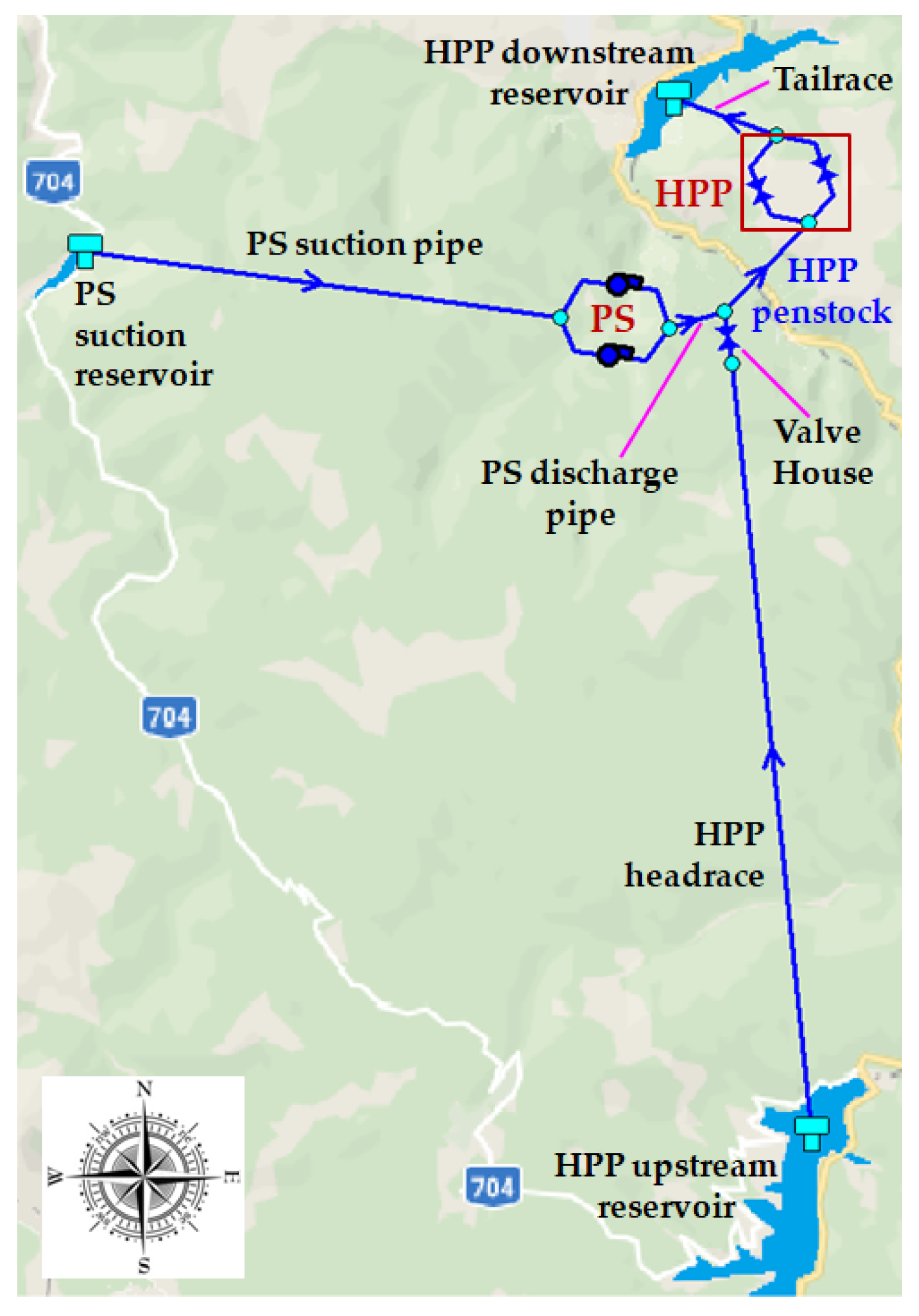
The selected case study is the Gâlceag hydropower facility [7,8,9,10,11,12] on Sebeș River, located in the west-central part of Romania. It consists of the following components (Figure 1):
  • Gâlceag Hydro Power Plant (commissioned in 1980)—an underground high head HPP, equipped with 2 vertical Francis turbines of 75 MW each, with the following rated parameters: 465 m turbine head, 2 × 22.8 m3/s total flow rate and 150 MW installed capacity;
  • Oașa Lake, which is the HPP upstream reservoir—a reservoir of 136.2 MCM (million cubic meters) active storage capacity (active volume) at the normal retention level of 1255 MASL (here, meters above the Black Sea level); it is retained by a 91 m high rockfill dam;
  • Tău Lake, which is the HPP downstream reservoir(21.3 MCM active volume at the normal retention level of 790 MASL); it is retained by a 78 m high arch dam;
  • Gâlceag Pumping Station (commissioned in 2003)—a PS equipped with 2 horizontal centrifugal pumps (double entry two stage pumps) of 10 MW each, with the following rated parameters: 260 m pumping head, 2 × 3 m3/s installed discharge and 20 MW total power;
  • Cugir Storage Lake, which is the PS suction reservoir (0.85 MCM active volume, at the normal retention level of 1007 MASL); it is retained by a 48 m high arch dam;
  • Hydraulic circuit of Gâlceag HPP: a headrace tunnel 8456 m long and 3.7 m in diameter (fed from HPP’s upstream reservoir—Oașa Lake), followed by a penstock 742 m long and 2.8 m in diameter (inclined by 32° with respect to the vertical); a double-chamber surge tank at the end of the headrace (that surge tank is not included in the numerical model, since the hydraulic analysis does not involve transients); a butterfly valve 2.8 m in diameter within the Valve House at the upper part of the penstock; at the bottom part of the penstock, a distributor splits the flow towards the two turbines; at the exit of HPP powerhouse, a tailrace tunnel 610 m long and 4 m equivalent diameter leads water to HPP’s downstream reservoir (Tău Lake);
  • Hydraulic circuit of Gâlceag PS: a headrace (PS suction pipe) 6500 m long and 2.8 m in diameter (fed from PS suction reservoir—Cugir Storage Lake); a surge tank at the end of the headrace, before the PS powerhouse (that surge tank is not included in the numerical model); the PS discharge pipe, 320 m long and 1.3 m in diameter, is connected to the upper part of HPP’s penstock—thus the pumped water is directly discharged into the penstock, to increase the energy output of the hydropower facility; a system of valves controls the pumped water.

3. EPANET Model

The numerical model was built in EPANET (Figure 2), based on the existing geometrical configuration of the hydraulic system. It consists of 3 tanks, 2 pumps, a throttle control valve (that mimics the existence of the butterfly valve in the Valve House), 2 general purpose valves (that mimic the turbines in EPANET [5,6]), 6 junctions and 5 pipes (diameters between 1300 mm and 4000 mm), with a total length of 16.63 km. The Darcy-Weisbach formulation was used to compute the head losses with the roughness set to 1 mm on all pipes. The calculations were performed for an extended time period of one hour, with a time step of one minute.
Based on data measured in situ [10], the characteristic curves of the pumps, namely the head—flow rate curve, and the efficiency—flow rate curve, were derived for the EPANET model through curve fitting, using the polynomials displayed in Figure 3.
The operation of the turbines was simulated in EPANET through general purpose valves (GPV). The head loss—flow rate curve, which has to be specified for a GPV, was replaced by the turbine head—flow rate curve. Based on data measured in situ [9], the characteristic curves of the turbines, namely the head—flow rate curve, and the efficiency—flow rate curve,were defined here by curve fitting, using the polynomials displayed in Figure 4. As there is no possibility of introducing the efficiency—flow rate curve of the turbines in EPANET, the calculations of delivered energy were performed outside of EPANET, in MS Excel, by importing from EPANET the head and flow rate values for each operation point of the turbine, at each time step, then computing in Excel the turbines efficiency for each flow rate value (through the regression polynomial displayed in Figure 4b), and finally, computing the corresponding power and produced energy.
For the 3 tanks that represent the HPP upstream, HPP downstream and PS suction reservoirs respectively, volume curves were introduced in EPANET. Each volume curve approximates the capacity curve of the corresponding reservoir, as in Figure 5. The minimum and maximum levels of the tanks were set at the minimal and normal retention levels of the corresponding reservoirs. In this study, the initial level of the PS suction tank was set to its normal retention level, while the initial level of the HPP downstream tank was set to the intermediate level of 770 MASL.
The initial level of the HPP upstream tank was decreased with a step of 1 m, starting from the normal retention level of the reservoir. After 20 steps, the initial level in the upstream tank reached the value of the average annual minimum level in Oașa Lake.

4. Results and Discussions

While the model was created in EPANET, it became obvious that this is not a proper pumped-storage facility. The volume of the PS suction reservoir is too small with respect to the volume of the HPP upstream reservoir. Even when the initial water level in the PS suction reservoir reaches the normal retention level (the lake is full), it only accounts for about 1.3% of the volume of the HPP upstream reservoir corresponding to the average annual minimum water level.
Three main scenarios (cases) were tested:
  • only the HPP in operation—thus the water flows from the HPP upstream reservoir to the HPP downstream reservoir;
  • only the PS in operation—thus the water is pumped from the PS suction reservoir into the HPP upstream reservoir, through the HPP penstock;
  • both HPP and PS in operation—thus the pumped water is discharged directly into the penstock and is added to the flow rate coming from the HPP upstream reservoir, flowing towards the hydraulic turbines.
Moreover, as stated before, the initial level in the HPP upstream reservoir was varied between the normal retention level (1255 MASL) and the average annual minimum level (1235 MASL), in steps of 1 m. The simulations in EPANET, and corresponding MS Excel post processing (as described in the previous section) allow the assessment of energy production and/or consumption in the studied scenarios.
Results for computations started with the initial water level equal to the normal retention level in both HPP upstream and PS suction reservoirs and equal to 770 MASL in HPP’s downstream reservoir, show that:
  • the power deliveredonly by the turbines (no pumps working) is about 115 MW;
  • the power required to pump water from the PS suction reservoir to the HPP upstream reservoir is about 15.5 MW;
  • the overall power delivered to the electric grid when all pumps and turbines are working (obtained as the difference between the power provided by the turbines and the power consumed by the pumps) is of about 113 MW.
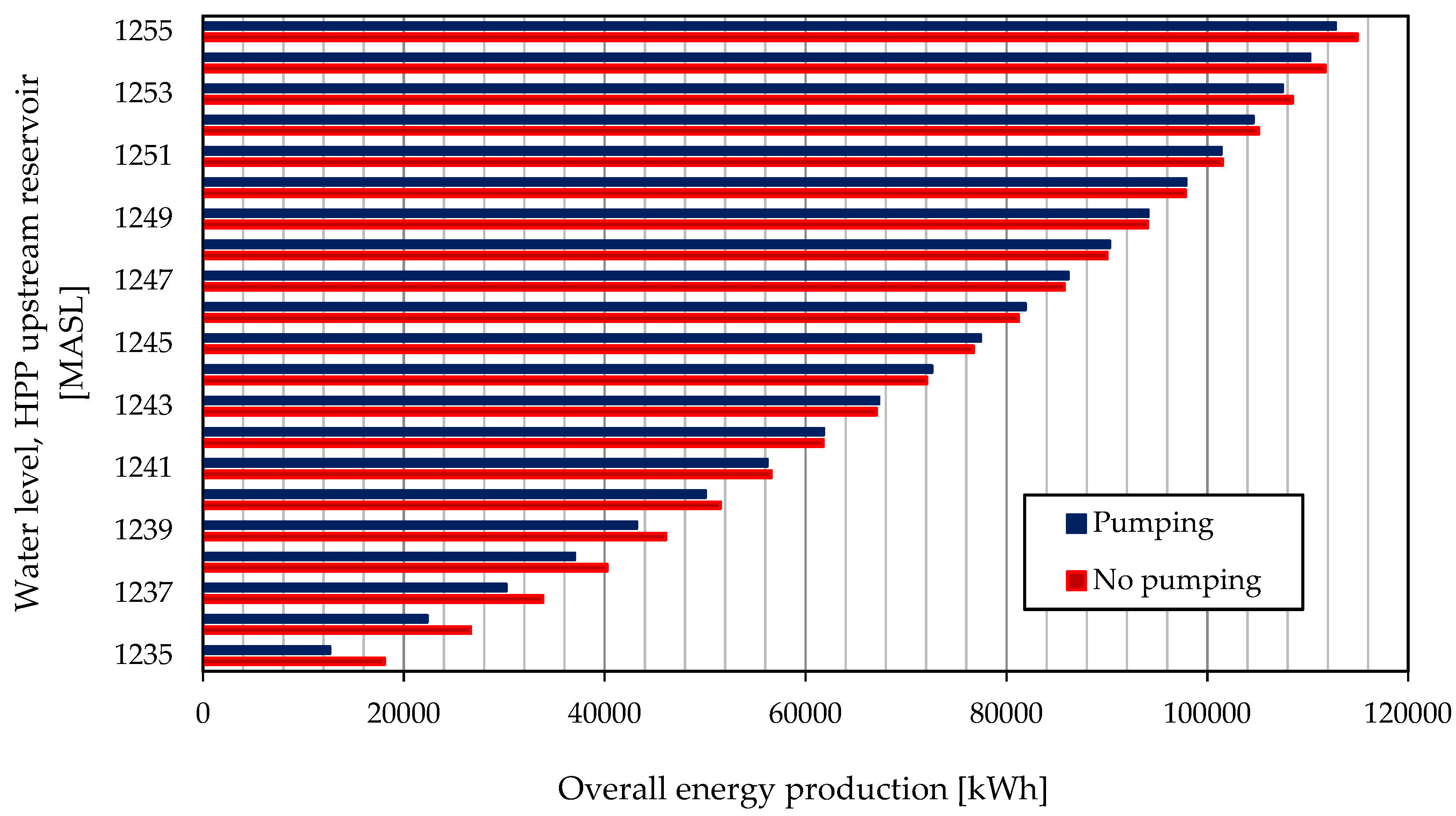
The relatively small difference between the first case and the third case provided a clue as to what could be the real purpose of such a combined facility. A comparison between the values obtained for the overall energy production in the cases (1) and (3), when the initial level in the HPP upstream reservoir was varied between the normal retention level and the average annual minimum level, is shown in Figure 6.
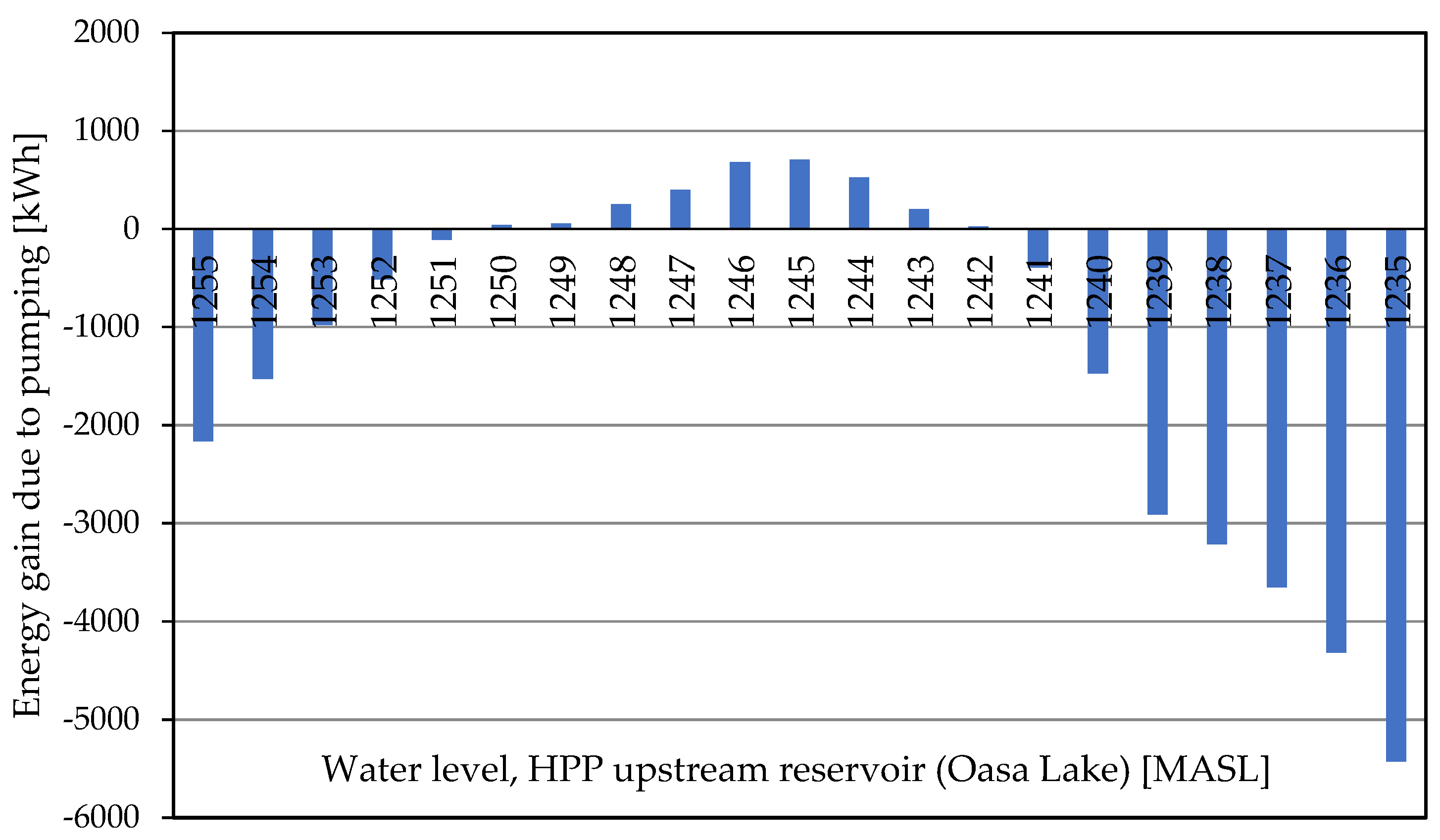
It is clear from Figure 6, that for some values of the water level in the HPP upstream reservoir, the overall quantity of energy provided by the system when all pumps and turbines are working, exceeds the quantity that would be provided if only the turbines would work. This occurs for water levels in the HPP upstream reservoir between 1250 and 1242 m above sea level. Differences are relatively small, so in order to increase the accuracy, we present in Figure 7 the gain in energy, obtained when pumps and turbines work together—i.e., the differences between the overall energy produced in case (3) and the energy produced in case (1); obviously positive values represent a gain in the overall energy delivered by the system, while negative values are energy losses, due to pumps’ operation. The maximum gain in energy is of about 700 kWh, obtained when the initial water level in the HPP upstream reservoir is of 1245 m above sea level.
The behavior of the system can be explained as follows. On one hand, the flow rate through the turbines is increased when pumps and turbines work together, with respect to the case when only turbines are used. On the other hand, the flow through the pumps is also increased as the level in the HPP upstream reservoir decreases.
For some intermediate values of the initial level in the HPP upstream tank, the flow increase shifts the values of the efficiency of both turbines and pumps towards bigger values, leading to more efficient production of energy in the turbines and more energy introduced by the pumps in the flow. In fact, for the initial water level of 1245 MASL in the HPP upstream tank, the average efficiency of the turbines in case (1), where no pumps are working, is of about 81%. In case (3), where turbines and pumps are working together, the average efficiency of the turbines is 84% and the average efficiency of the pumps is 75%. The 3% of difference in efficiency for the turbines, coupled to the increase of flow rate through the turbines, lead to a gain in energy produced of about 16.7 MWh, while the pumps are consuming about 16 MWh.
This energy gain does not necessarily mean that the system is more efficient. For the initial water level in the HPP upstream reservoir of 1245 MASL, in case (1), where only turbines are working, if we consider that the useful energy is the energy provided by the turbines to the grid, and the consumed (available) energy is the hydraulic energy corresponding to the flow rate at the turbines gross head (height difference between the levels of the HPP upstream and downstream reservoirs), then the overall efficiency of the system results of about 79.3%.
For the case (3), where all pumps and turbines are working, starting from the same initial water level in the HPP upstream reservoir, the overall efficiency of the system results of about 79.2%. Here we considered that the useful energy is the energy provided by the turbines to the grid, and the consumed energy is the sum of the hydraulic energy corresponding to the flow rate that comes from the HPP upstream reservoir at the turbines gross head, the hydraulic energy corresponding to the pumped flow rate at the height difference between the levels of the PS suction reservoir and the HPP downstream reservoir, and finally the energy consumed by the pumps.
As in both cases, (1) and (3), the overall efficiency of the system is practically the same, in this respect it may seem like a good idea to use the pumps when the initial water level in the HPP upstream reservoir is between 1250 and 1242 MASL, as more energy is provided to the electric grid.

5. Conclusions

This paper presents the EPANET numerical model of a Hydro Power Plant coupled to a Pumping Station, in a complex system existing in Romania. Measured characteristic curves of the pumps and the turbines were used in the model.
Three main scenarios were tested: (1) only HPP in operation (where water flows as for any classical HPP site); (2) only PS in operation (where water is pumped from the PS suction reservoir to supply the HPP upstream reservoir, through the HPP penstock); (3) both HPP and PS in operation (where the pumped water is discharged directly into the penstock, increasing the flow rate towards the HPP). The initial water level in the HPP upstream reservoir was varied (by 1 m steps, over 20 m), starting from the normal retention level down to the average annual minimum level.
The simulations allow the assessment of energy production and/or consumption in the studied cases, and can help decision makers of the hydropower company that manages the system, to choose wittingly the operation mode of the facility. The results show that for water levels in the HPP upstream reservoir between 1250 and 1242 m above sea level, more energy is extracted from the system if all turbines and pumps work—case (3).
Further work is necessary in order to assess the influence of the initial levels in the PS suction reservoir and in the HPP downstream reservoir, on the operation of the system. Partial operation of the facility (only one pump in operation and/or only one turbine) has also to be taken into account, for a more complete analysis.

References

  1. Constantin, C.; Eremia, M.; Bulac, C. Power system transient stability improvement using series FACTS devices. U.P.B. Sci. Bull. Ser. C 2015, 77, 259–268. Available online: https://www.scientificbulletin. upb.ro/rev_docs_arhiva/full617_802587.pdf (accessed on 12 May 2018).
  2. Pérez-Díaz, J.I.; Chazarra, M.; García-González, J.; Cavazzini, G.; Stoppato, A. Trends and challenges in the operation of pumped-storage hydropower plants. Renew. Sustain. Energy Rev. 2015, 44, 767–784. [Google Scholar] [CrossRef]
  3. Boamba, C.E.; Mirea, C.; Eremia, M.; Tristiu, I. Influence of renewable sources on Romanian power system. U.P.B. Sci. Bull. Ser. C 2014, 76, 191–198. Available online: https://www.scientificbulletin.upb.ro/rev_docs_arhiva/full065_340453.pdf (accessed on 12 May 2018).
  4. Anagnostopoulos, J.S.; Papantonis, D.E. Study of pumped storage schemes to support high RES penetration in the electric power system in Greece. Energy 2012, 45, 416–423. [Google Scholar] [CrossRef]
  5. Georgescu, S.-C.; Georgescu, A.-M. EPANET Manual; (In Romanian); Printech Press: Bucharest, Romania, 2014; pp. 102–136. [Google Scholar]
  6. Rossman, L. EPANET 2 Users Manual; EPA/600/R-00/057; U.S. Environmental Protection Agency (EPA): Cincinnati, OH, USA, 2000; pp. 27–79. [Google Scholar]
  7. Popa, F.; Popa, B.; Popescu, C. Assessment of pumped storage plants in Romania. Energy Procedia 2017, 112, 473–480. [Google Scholar] [CrossRef]
  8. Bucur, D.M.; Dunca, G.; Cervantes, M.J.; Calinoiu, C.; Isbasoiu, E.C. Simultaneous transient operation of a high head hydro power plant and a storage pumping station in the same hydraulic scheme. IOP Conf.Ser. Earth Environ. 2014, 22, 042015. [Google Scholar] [CrossRef]
  9. Bucur, D.M.; Dunca, G.; Isbasoiu, E.C.; Calinoiu, C.; Rosioru, O.T. Analysis of operating parameters during normal and transient regimes of a high head hydro power plant. U.P.B.Sci. Bull.Ser. D 2012, 74, 51–58. Available online: https://www.scientificbulletin.upb.ro/rev_docs_arhiva/full298_442267.pdf (accessed on 12 May 2018).
  10. Dunca, G.; Bucur, D.M.; Isbasoiu, E.C.; Calinoiu, C. Transient behavior analysis. Study case: pumping station Gâlceag. U.P.B. Sci. Bull., Series C 2007, 69, 651–658. [Google Scholar]
  11. Hidroelectrica.Sebes Hydropower Branch. Available online: http://www.hidroelectrica.ro/Details.aspx?page=42 (accessed on 12May 2018).
  12. Hidroconstructia S.A. Projects/Hydroenergetics/Sebes Branch. Available online: http://www.hidroconstructia.com/eng/proiecte.html (accessed on 12May 2018).
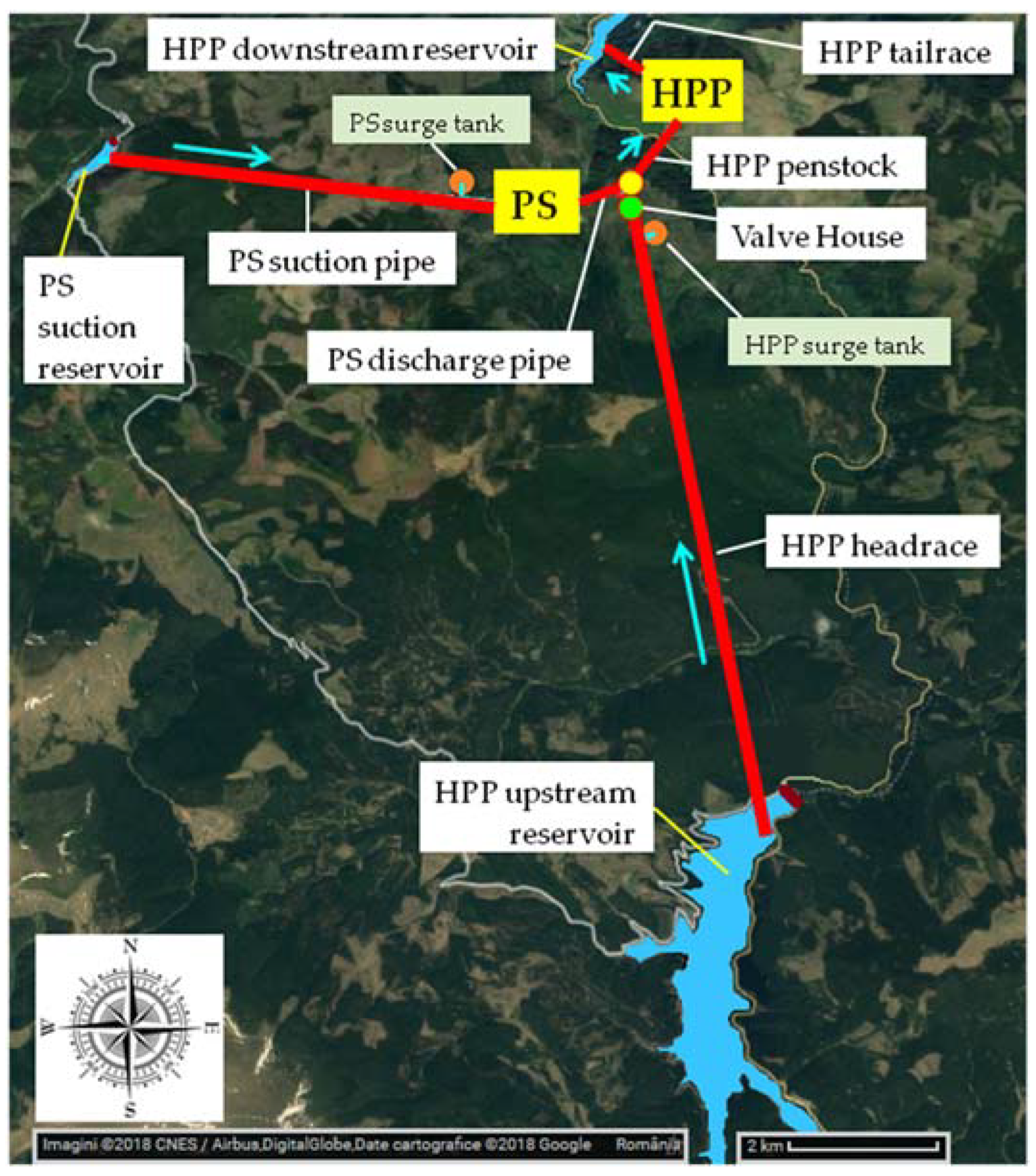
Figure 1. Hydropower facility scheme, superposed on the geographical map of the area: Gâlceag Hydro Power Plant (HPP) and Gâlceag Pumping Station (PS).
Proceedings 02 00608 g001
Figure 2. Numerical model of the hydropower facility, built in EPANET: Gâlceag HPP (2 turbines as general purpose valves); Gâlceag PS (2 pumps); 3 tanks (HPP upstream/downstream reservoirs and PS suction reservoir); 5 pipes (HPP headrace/penstock/tailrace and PS suction/discharge pipes); Valve House (as throttle control valve); 6 junctions.
Proceedings 02 00608 g002
Figure 3. Pump characteristic curves used in the numerical model: (a) Head—flow rate curve; (b) Efficiency—flow rate curve.
Proceedings 02 00608 g003
Figure 4. Turbine characteristic curves used in the numerical model: (a) Head—flow rate curve (attached to GPV in EPANET, as head losses—flow rate curve); (b) Efficiency—flow rate curve.
Proceedings 02 00608 g004
Figure 5. Tanks’ capacity curves used in the numerical model: (a) HPP upstream tank; (b) HPP downstream tank; (c) PS suction tank.
Proceedings 02 00608 g005
Figure 6. Overall energy production [kWh] obtained at different values of the initial water level in the HPP upstream reservoir (Oașa Lake).
Proceedings 02 00608 g006
Figure 7. Energy gain [kWh] due to pumping for various levels in the HPP upstream reservoir.
Proceedings 02 00608 g007
Publisher’s Note: MDPI stays neutral with regard to jurisdictional claims in published maps and institutional affiliations.