RISAT-1 Compact Polarimetric Calibration and Decomposition †


Abstract
:1. Introduction
2. Study Area and Dataset
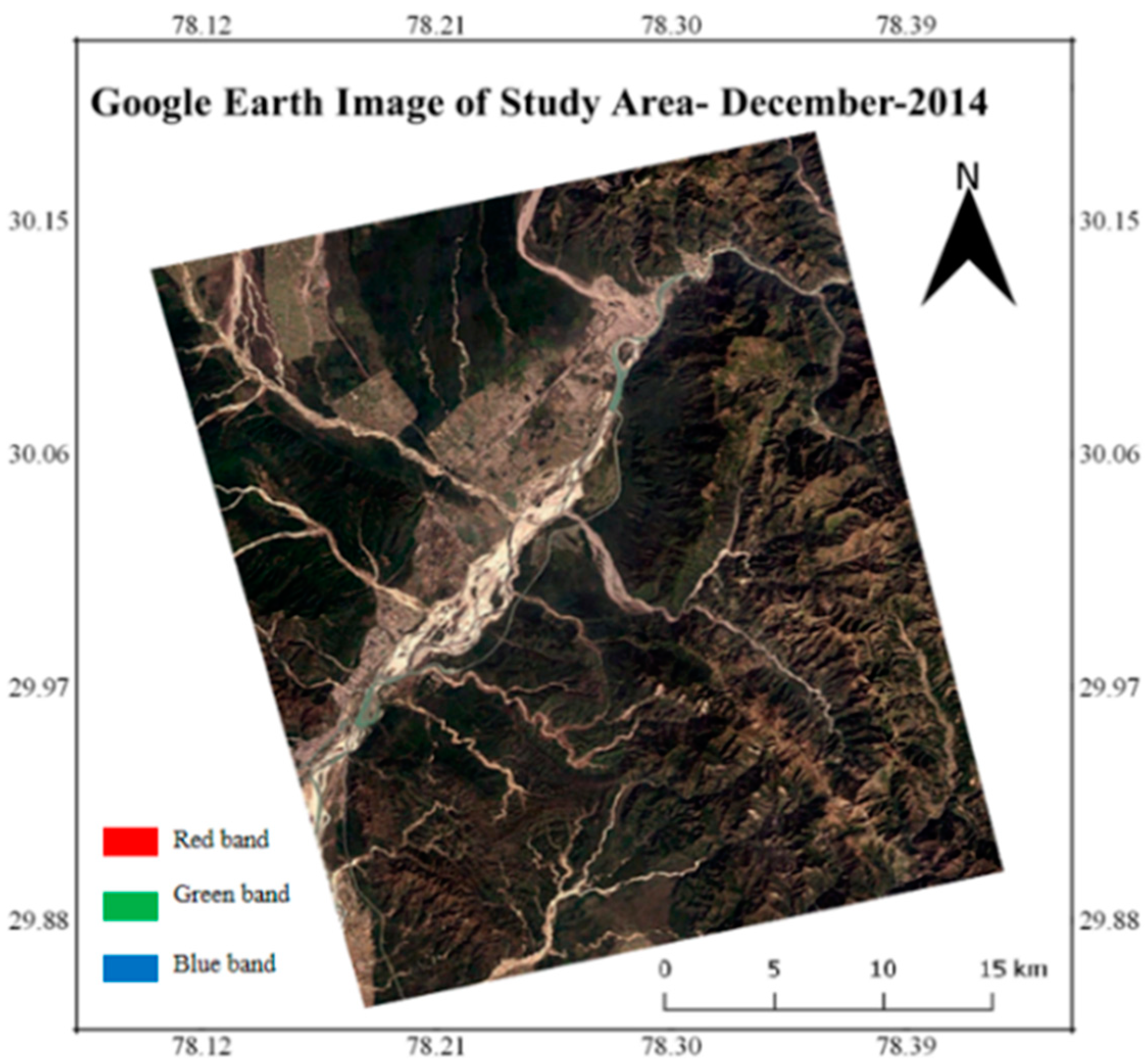
2.1. Study Area
2.2. Dataset
3. Methodology
4. Results and Discussions
5. Conclusions
Acknowledgments
Conflicts of Interest
References
- Touzi, R. Compact-Hybrid versus Linear-Dual and Fully Polarimetric SAR. In Proceedings of the 4th International Workshop on Science and Applications of SAR Polarimetry and Polarimetric Interferometry, Frascati, Italy, 26–30 January 2009. [Google Scholar]
- Jayasri, P.V. Implementation of RISAT-1 Hybrid Polarimetric Decomposition Techniques and Analysis Using Corner Reflector Data. J. Indian Soc. Remote Sens. 2018, 46, 1005–1012. [Google Scholar] [CrossRef]
- Raney, R.K. Hybrid-Polarity SAR Architecture. IEEE Trans. Geosci. Remote Sens. 2007, 45, 3397–3404. [Google Scholar] [CrossRef]
- Dubois-Fernandez, P.C.; Souyris, J.-C.; Angelliaume, S.; Garestier, F. The Compact Polarimetry Alternative for Spaceborne SAR at Low Frequency. IEEE Trans. Geosci. Rem. Sens. 2008, 376, 536–541. [Google Scholar] [CrossRef]
- Kumar, S.; Gupta, V.; Gonnuru, P.; Joshi, S.K. PolSAR calibration and reconstruction of hybrid polarimetric RISAT-1 data for pseudo quad-pol decomposition: a comparison with quad-pol. In Proceedings of the SPIE ASIA-PACIFIC REMOTE SENSING, New Delhi, India, 4–7 April 2016. [Google Scholar]
- Chang, Y.; Li, P.; Yang, J.; Zhao, J.; Zhao, L.; Shi, L. Polarimetric calibration and quality assessment of the GF-3 satellite images. Sensors (Switz.) 2018, 18, 1–12. [Google Scholar] [CrossRef] [PubMed]
- Sturdivant, R.; Harris, M. Transmit/receive modules. In Transmit Receive Modules for Radar and Communication Systems; Artech House: Norwood, MA, USA, 2016; Chapter 2, Section 2.5.7; pp. 44–45. [Google Scholar]
- Gail, W.B. Effect of Faraday rotation on polarimetric SAR. IEEE Trans. Aerosp. Electron. Syst. 1998, 34, 301–308. [Google Scholar] [CrossRef]
- Misra, T.; Kirankumar, A.S. RISAT-1: Configuration and performance evaluation. In Proceedings of the 2014 XXXIth URSI General Assembly and Scientific Symposium (URSI GASS), Beijing, China, 16–23 August 2014; pp. 3–6. [Google Scholar]
- Truong-Loï, M.L.; Dubois-Fernandez, P.; Pottier, E.; Freeman, A.; Souyris, J.C. Potentials of a compact polarimetric SAR system. In Proceedings of the 2010 IEEE International Geoscience and Remote Sensing Symposium, Honolulu, HI, USA, 25–30 July 2010; pp. 742–745. [Google Scholar]
- Sharma, S.; Dadhich, G.; Rambhia, M.; Mathur, A.K.; Prajapati, R.P.; Patel, P.R.; Shukla, A. Radiometric calibration stability assessment for the risat-1 sar sensor using a deployed point target array at the desalpar site, rann of kutch, india. Int. J. Remote Sens. 2017, 38, 7242–7259. [Google Scholar] [CrossRef]
- Cloude, S.R.; Goodenough, D.G.; Chen, H. Compact decomposition theory. IEEE Geosci. Remote Sens. Lett. 2012, 9, 28–32. [Google Scholar] [CrossRef]


| Date of Acquisition | Mode | Polarizations | Swath (Km) | Resolution (Az × Rg) | Look Direction |
|---|---|---|---|---|---|
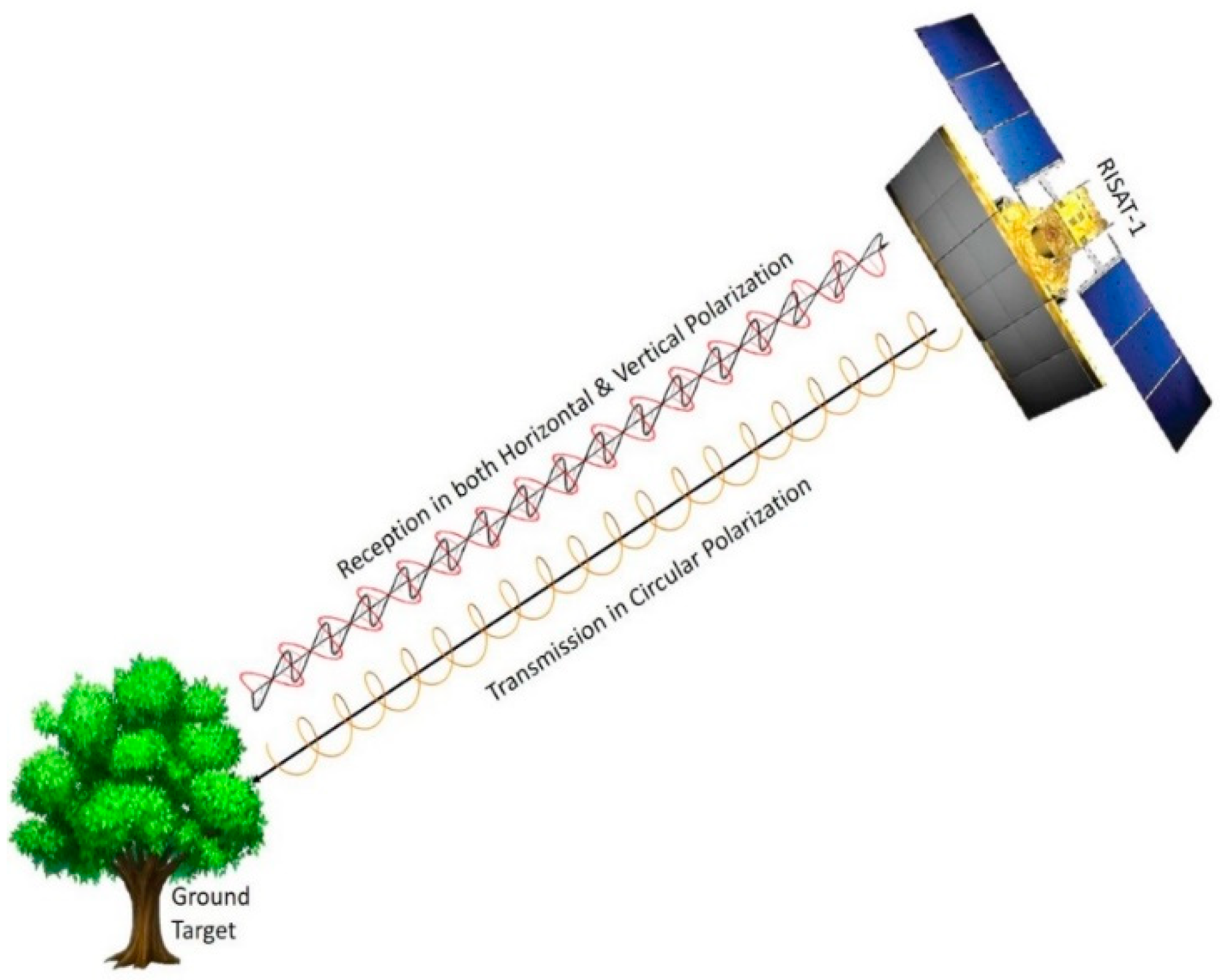
| 5-November 2014 | FRS-1 | RH, RV | 25 | 3 × 2 m | Right |
| Distortion Parameter | Channel Imbalance Parameter ‘’ | Faraday Rotation Angle ‘’ | ||
|---|---|---|---|---|
| Value | 0.8715 + 0.2086j | −0.0770 − 0.1996j | −0.9576 + 0.6808j | 0.01927 degrees |
| Ground Target | Before Polarimetric Calibration | After Polarimetric Calibration | ||||
|---|---|---|---|---|---|---|
| Odd Bounce Scattering Magnitude (dB) | Volume Scattering Magnitude (dB) | Double Bounce Scattering Magnitude (dB) | Odd Bounce Scattering Magnitude (dB) | Volume Scattering Magnitude (dB) | Double Bounce Scattering Magnitude (dB) | |
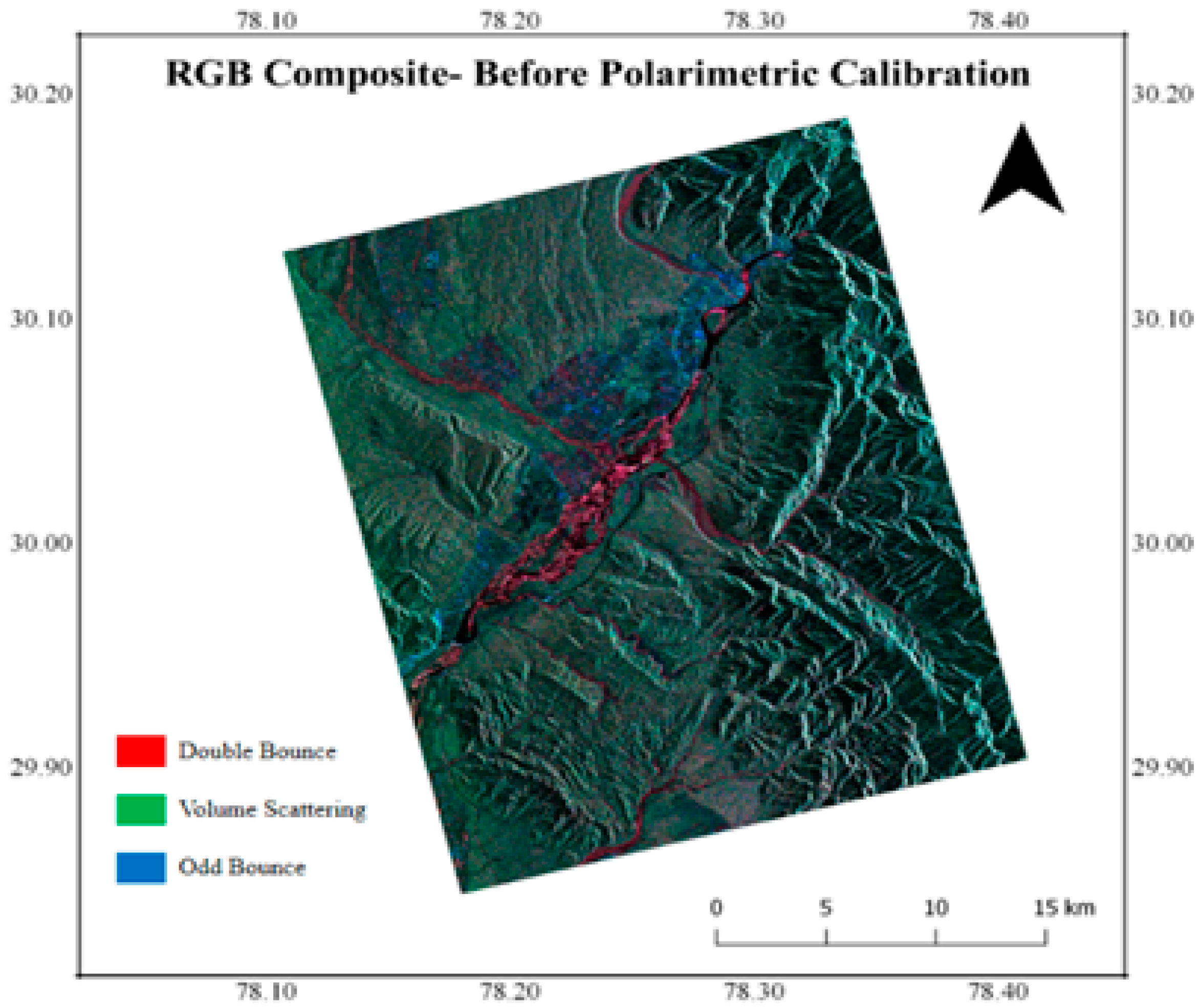
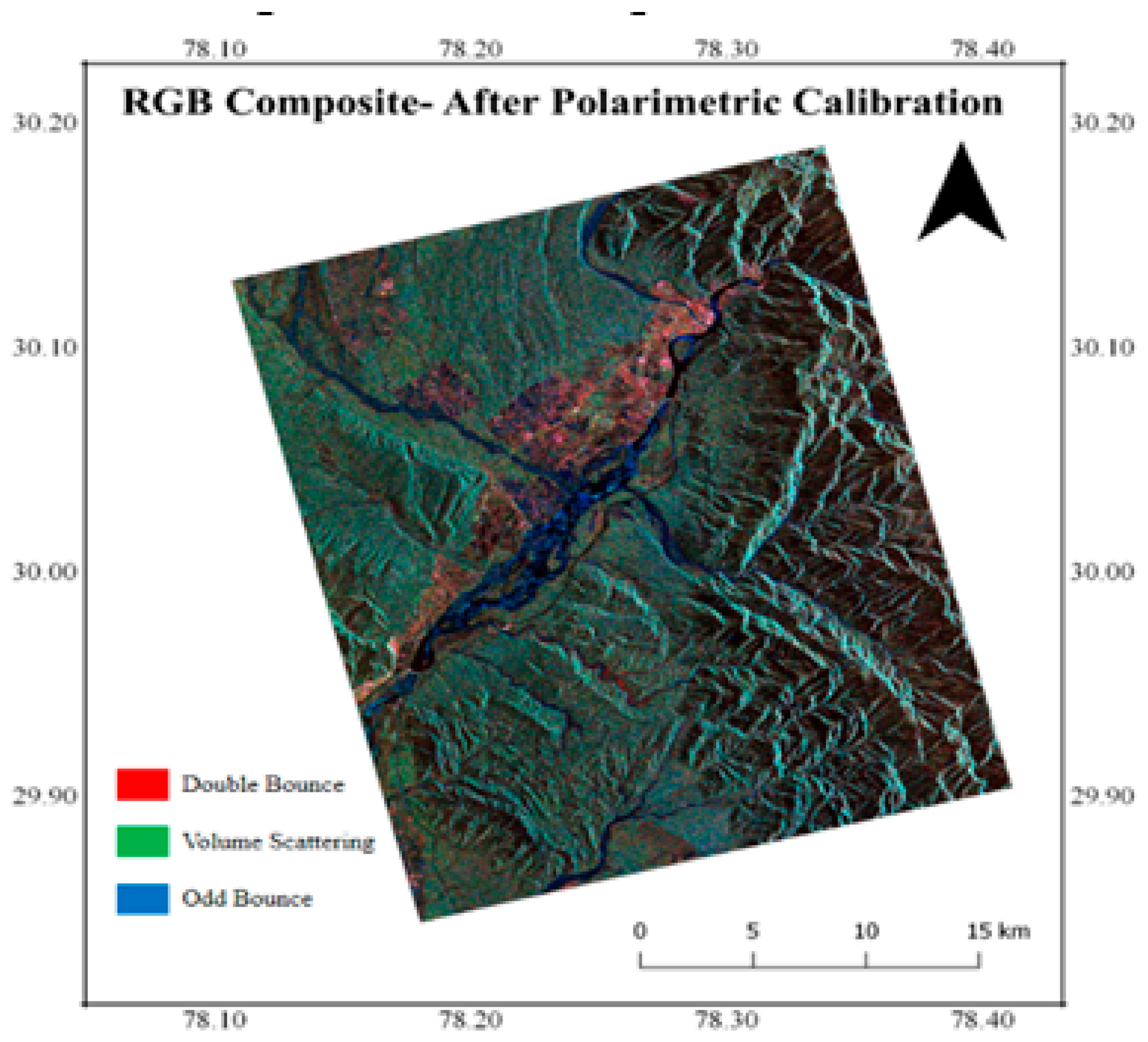
| Dry river bed | −25.28 | −19.43 | −16.09 | −28.36 | −36.25 | −55.46 |
| Urban structures | −11.65 | −15.31 | −25.93 | −49.88 | −33.52 | −27.36 |
| Thick Vegetation | −12.89 | −7.73 | −21.25 | −27.76 | −21.71 | −28.40 |
© 2019 by the authors. Licensee MDPI, Basel, Switzerland. This article is an open access article distributed under the terms and conditions of the Creative Commons Attribution (CC BY) license (https://creativecommons.org/licenses/by/4.0/).
Share and Cite
Babu, A.; Kumar, S.; Agrawal, S. RISAT-1 Compact Polarimetric Calibration and Decomposition. Proceedings 2019, 18, 3. https://doi.org/10.3390/ECRS-3-06189
Babu A, Kumar S, Agrawal S. RISAT-1 Compact Polarimetric Calibration and Decomposition. Proceedings. 2019; 18(1):3. https://doi.org/10.3390/ECRS-3-06189
Chicago/Turabian StyleBabu, Arun, Shashi Kumar, and Shefali Agrawal. 2019. "RISAT-1 Compact Polarimetric Calibration and Decomposition" Proceedings 18, no. 1: 3. https://doi.org/10.3390/ECRS-3-06189
APA StyleBabu, A., Kumar, S., & Agrawal, S. (2019). RISAT-1 Compact Polarimetric Calibration and Decomposition. Proceedings, 18(1), 3. https://doi.org/10.3390/ECRS-3-06189