Abstract
Construction, laboratory tests as well as the first field application of a new fibre-optic rotational seismograph is presented. The system based on fibre-optic gyroscope (FOG) with measured Angle Random Walk on range 10−8 rad/Sqrt(s) and a few rad/s maximum detectable amplitude of rotation in frequency range from DC to 328.12 Hz designed it for rotational seismology area of interest. This work presents also exemplary relevant measurements which were conducted using two seismographs in the geophysical observatory in Książ region, Poland.
1. Introduction
Paper deals with innovative sensor suitable for rotational seismology which falls within rotational ground movements from earthquakes, explosions, and ambient vibrations [1]. In spite of growing popularity of the rotational seismology there are still lack of appropriate rotational sensors for its field application also in form of seismograph which contains rotational sensor, data acquisition system with precise sensor localization and precision time monitoring. Nevertheless, rotational sensors used in field application should meet a number of technical requirements forced by rotational seismology which one can find in paper [2].
From above reasons in this paper we describe construction, laboratory test as well as results of field application of FOSREM® - the innovative Fibre-Optic Rotational Seismograph. During the field test conducted in the geophysical observatory in Książ, Poland, the torsion and tilt effects resulting from mining seismic quakes induced by copper mining operations have been recorded with high accuracy.
2. Construction and Laboratory Investigation of FOSREM®
FOSREM® contains two main part: a rotational sensor–FORS (Fibre-Optic Rotational Seismometer) and data center—a special WEB FOSREM (Telemetric Server) used for the data storage, the monitoring the FORSs work, as well as for the remote control of their parameters. Each FORS has been constructed by applying a minimum open loop FOG configuration with MIOC where the Sagnac effect [3] produces a phase shift between two counter-propagating light beams proportional to a measured rotation rate [4]. The main advantage of such solution is its complete insensitivity to linear motions and a direct measurement of a rotational rate. The FORS can be generally divided into two basic parts: optical and electronic. The optical part according to the schema in the Figure 1a assures the Sagnac effect reversibility. The optimization of the optical part–5000 m sensor loop with 0.21 m diameter and total optical losses equal to 19.63 dB, have led to the theoretical sensitivity of FORS equal to 3.07 × 10⁻⁸ rad/s/√Hz. Signal processing is secured by FORS electronic part shown in Figure 1b) which contains digital units with sophisticated software for system control and real time data computation. All electronic modules (amplifier—MAMP, filter—MFLT, MIOC signal—MSIN, SLED control–MLAS) are connected to the FPGA using the hardware interface module. Dedicated IP core collects raw data from ADCs and transfer it to ARM Cortex-A9 processor. This processor performs all computation and communication transfer to communication unit or to Internet. The connection provides data transmission and power supply over a single STP cable within a distance of 100 m. Finally, the obtained results are stored on a hard disc and transmitted to the WEB FOSREM which can remote control all FORSs. The remote control and small dimension of FORS (360 × 360 × 180 mm) and weight ~10 kg makes it (see Figure 1c) a fully mobile device.
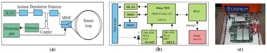
Figure 1.
General construction of FORS: (a) block diagram of optical part, (b) block diagram of electronic part, (c) technical realization for FORS-2.
A number of experimental tests were carried out to confirm FORSs parameters and reliability. As example, a good linearity for FORSs regarding detection rotation with high angular velocity up to radian per second is presented in Figure 2a. Moreover Figure 2b presents result of the Allan variance analysis [5,6] for FORS-2, which indicated that ARW (Angle Random Walk) is equal to 4.9 × 10⁻⁸ rad/√s whereas BI (Bias Instability) has level of 1.20 × 10⁻⁸ rad/s. The obtained value of ARW is in good correlation with theoretical sensitivity of FORS above mentioned. Because determined parameters fulfil all requirements described for rotational seismology [2], that can be concluded so FOSREM is an appropriate for registration of rotational events associated with rotational seismology.
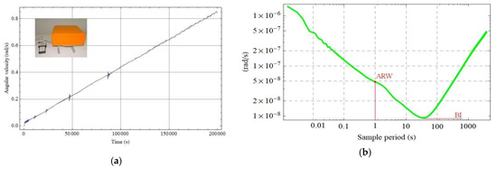
Figure 2.
Results of FORS-2 laboratory investigation: (a) recording rotational speed with increasing angular velocity up to 0.9 rad/s, (b) the Allan variance analysis.
3. FOSREM® in the Field Application
The set of two FORSs (recognized as FOSREM-1 and FOSREM-2) have been mounted in the geophysical observatory of the Polish Academy of Science in Książ, Poland which is located in the area of a mining activity (position φ = 50°50′31″ N, λ = 16°17′29″ E)
The obtained data (stored at WEB FOSREM) were analyzed in a specially designed Matlab script which allows to simultaneously read the data from both FOSREMs and to calculate the Pearson’s correlation coefficient (PC) between the signals from FOSREMs [7]. Figure 3 presents the exemplary data of the recorded torsion and tilt by two installed devices. The average value of the PC between presented signals is of the order of 0.94 ± 0.01 which indicates a very high compatibility of the waveforms. Every figure shows also information about the absolute value of maximal amplitude of the signal (|F-1 max|, |F-2 max|), as well as a EF—energy coefficient (E|F-1|, E|F-2|) for FOSREM-1 and FOSREM-2, respectively.
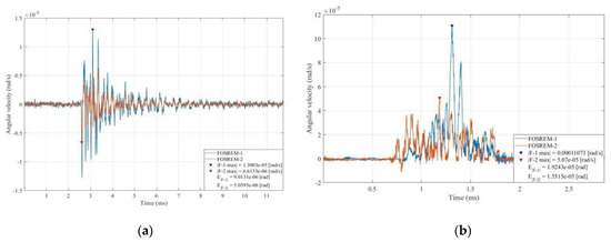
Figure 3.
Data recorded by the FOSREMs in the geophysical observatory in Książ, Poland: (a) torsion event on the 1 December 2017, at 12:19 UTC, (b) tilt event on the 13 December 2017, at 11:15 UTC.
In the Table 1 we present a collection of recorded torsion and tilt events in period 29 August 2017–8 January 2018. There is information about recorded maximal signal amplitude, energy coefficient (EF) calculated numerically using a method of rectangles of the Riemann integral as well as correlation coefficient (PC) between FOSREM-1 and -2. The energy coefficient of tilt can be physically directly indicate with a value of an angle of a rock’s crump.

Table 1.
Data recorded by the FOSREMs in the geophysical observatory in Książ, Poland.
One can see that torsion recordings are characterized by the higher value of the PC (0.91 ± 0.07) between the FOSREMs than for tilt recordings (0.63 ± 0.1). Nevertheless, both values of the PC indicated good compatibility of the FOSREMs’ signals. The value of the maximal recorded amplitude (1.02 × 10⁻⁴ rad/s) as well as energy coefficient (8.11 × 10⁻⁵ rad) for tilt events is much higher than for recorded torsion events (3.15 × 10⁻⁶ rad/s; 5.78 × 10⁻⁵ rad). It is caused by the nature of the tilt phenomenon which is rapider due to its source of generation, for example caving.
4. Conclusions
The FOSREM® presented in this paper have been constructed to meet completely technical requirements for rotational seismology. It used autonomous and mobile fibre-optic rotational seismometers enable to detect rotational movements in wide amplitude (5∙10-8 rad/s–10 rad/s) as well as frequency range (DC-328.12 Hz). Moreover, the FOSREM® is fully remote controlled as well as it is suited for a continuous, autonomous work in very long period of time, thus it is useful for a systematic seismological investigation at any place.
The gathered data in the geophysical observatory in Książ, Poland by set of two FORSs show a very high correlation coefficient between the applied sensors which confirm the records’ reliability. All recorded data resulting from mining seismic quakes induced by copper ore mining operations. The data clearly indicated the rapid nature of tilt phenomenon which is reflected in higher value of recorded signal amplitude than in case of torsion recordings. In authors’ knowledge, the presented in this paper recordings of tilt effects caused by crumps at local mines are one of the carried out research in the world. FOSREMs give great opportunities for spreading knowledge about seismic rotational events, as well as torsional effects existing in any engineering constructions.
Author Contributions
conceptualization, L.R.J.; methodology, A.K.; software, J.K.K.; electronic concept and design, H.A.K.; validation, A.K. and Z.K.; investigation, K.P.T.; writing—draft, review and editing, A.K. and L.R.J.
Acknowledgments
This work was financial supported by the Ministry of National Defence Republic of Poland—project no. GBMON/13-995/2018/WAT, the National Science Centre, Poland—project 2016/23/N/ST10/02508 as well as program POIR.04.02.00-14-A003/16 “EPOS—System Obserwacji Płyty Europejskiej”.
Conflicts of Interest
The authors declare no conflict of interest.
References
- Lee, W.H.K.; Celebi, M.; Todorovska, M.I.; Igel, H. Introduction to the Special Issue on Rotational Seismology and Engineering Applications. Bull. Seism. Soc. Am. 2009, 99, 945–957. [Google Scholar] [CrossRef]
- Jaroszewicz, L.R.; Kurzych, A.; Krajewski, Z.; Marć, P.; Kowalski, J.K.; Bobra, P.; Zembaty, Z.; Sakowicz, B.; Jankowski, R. Review of the Usefulness of Various Rotational Seismometers with Laboratory Results of Fibre-Optic Ones Tested for Engineering Applications. Sensors 2016, 16, 2161. [Google Scholar] [CrossRef] [PubMed]
- Sagnac, G. L’ether lumineux demontre par l’effet du vent relatif d’Etherdanus un interferometre enrotation uniforme. C. R. l’Acad. Sci. 1913, 95, 708–710. [Google Scholar]
- LeFevre, H.C. The Fiber Optic Gyroscope, 2nd ed.; Artech House: Norwood, MA, USA, 2008; pp. 154–196. [Google Scholar]
- IEEE Standard Specification Format Guide and Test Procedure for Single-Axis Interferometric Fiber Optic Gyros; IEEE-SA Standards Board: New York, NY, USA, 1997.
- Allan Variance: Noise Analysis for Gyroscopes. Freescale Semiconductor Application Note AN5087, 2015.
- Hall, G. Pearson’s Correlation Coefficient. Available online: http://www.hep.ph.ic.ac.uk/~hallg/UG_2015/Pearsons.pdf (accessed on 13 March 2018).
Disclaimer/Publisher’s Note: The statements, opinions and data contained in all publications are solely those of the individual author(s) and contributor(s) and not of MDPI and/or the editor(s). MDPI and/or the editor(s) disclaim responsibility for any injury to people or property resulting from any ideas, methods, instructions or products referred to in the content. |
© 2019 by the authors. Licensee MDPI, Basel, Switzerland. This article is an open access article distributed under the terms and conditions of the Creative Commons Attribution (CC BY) license (https://creativecommons.org/licenses/by/4.0/).