Abstract
This paper presents the design of a new force/tactile sensor for robotic applications. The sensor is suitably designed to provide the robotic grasping device with a sensory system mimicking the human sense of touch, namely, a device sensitive to contact forces, object slip and object geometry. This type of perception information is of paramount importance not only in dexterous manipulation but even in simple grasping task, especially when objects are fragile and deformable, such that only a minimum amount of grasping force can be applied to hold the object without damaging it.
1. Introduction
The ability of modern robots to grasp and manipulate objects in a dexterous way is far from the human manipulation skills. One of the main features that a grasping device should possess is the ability to grasp any kind of object as firmly as possible. Such feature requires the capability to control the grasping force, which requires proper measurement of contact forces and moments as well as contact locations. These kind of measurement can be performed with the combined use of tactile and force sensors [1] or by resorting to integrated force/tactile sensors [2]. Recently, this kind of sensor has been integrated into commercial parallel grippers for controlling both linear and rotational slippage of rigid objects of parallelepiped shape [3] demonstrating that it allows safe grasping under uncertain conditions.
In the present paper the design of a new and upgraded version of a force/tactile sensor is presented. The new sensor design starts from the main requirement to manipulate objects of generic shape avoiding both linear and rotational slippage. This goal leads to the need of a soft contact surface so that significant torsional moments can be held by the sensor.
2. The Force/Tactile Sensor
The proposed sensor is based on the working principle firstly presented in [2]. The basic idea foresees a suitably designed deformable layer positioned above a discrete number of sensible points (called “taxels”), in order to transduce the external force and moment, applied to the sensor, into deformations, which are measured by the taxels. The taxels, spatially distributed below the deformable layer, provide a set of signals corresponding to a distributed information (called “tactile map”) about the sensor deformations. The whole tactile map allows, after a calibration procedure, to estimate contact force and moment together with information about the orientation of the contact surface and object properties.
The developed sensor is mainly constituted by three components: a Printed Circuit Board (PCB), a rigid grid and a deformable cap. For this work, the design of all these components has been optimized. The first improvement with respect to [2] concerns the type of integrated taxels. In detail, for each taxel, the emitter/receiver couple is here constituted by a unique optoelectronic component: a Surface Mount Technology (SMT) photo-reflector, manufactured by New Japan Radio Co., with part number NJL5908AR. This device integrates in the same package the emitter, an infrared Light Emitting Diode (LED), with a peak wavelength at 920nm and the receiver, a PhotoTransistor (PT), with a peak wavelength at 880 nm. These devices allow the realization of the PCB with a standard robotized pick-and-place procedure, which guarantees the minimization of uncertainties on the taxel positioning and on the relative orientation among the emitter and the receiver of a taxel. These uncertainties negatively affected the sensor performance when separated components were used. Differently from [8], the number of taxels have been increased in order to obtain a sensitive area sufficiently wide to manipulate a larger number of objects. In particular, the optoelectronic section of the PCB integrates 25 taxels, organized in a 5x5 matrix, by obtaining a total area to cover with the deformable layer equal to 21.3x21.3 mm2. The PCB design also foresaw specific holes for the mechanical assembly between the electronic layer and the other sensor components (see Figure 1).
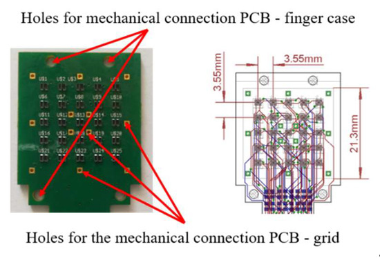
Figure 1.
Details of the sensitive area on the PCB (left) and corresponding layout (right) with dimensions.
For each taxel, the conditioning electronics is constituted by two resistors: one to drive the LED and a second to transduce the photocurrent measured by the PT into a voltage compatible with the Analog-to-Digital (A/D) converters. Two 12-bit A/D converters (manufactured by Analog Devices, with part number AD7490) with 16 channels and a Serial Peripheral Interface (SPI), has been integrated in the PCB design. for the conversion of the 25 taxel signals. In order to integrate the tactile sensor in a standard parallel gripper, for this work, a microcontroller-based section has been integrated into the PCB design. In particular, an interfacing section constituted by the microcontroller PIC16F1824, manufactured by Microchip Technology, has been added on a separate rigid board, connected to the previous described part via a flexible section. The integration of the microcontroller allows to obtain a fully integrated sensor with a programmable device used to interrogate the sensor via a standard serial interface already available in most commercial grippers. The board is completed by a standard low-noise voltage regulator with an input voltage range up to 12V (typical range of supply voltage available on commercial grippers) and an output voltage equal to 3:3V to supply the whole PCB. Figure 2 reports the layout and some pictures of the whole rigid-flex PCB, with the dimensions and the description of all components. In the realized prototype, the connector compatible with the sensor port available on the commercial grippers WSG-series, manufactured by Weiss Robotics, has been integrated.
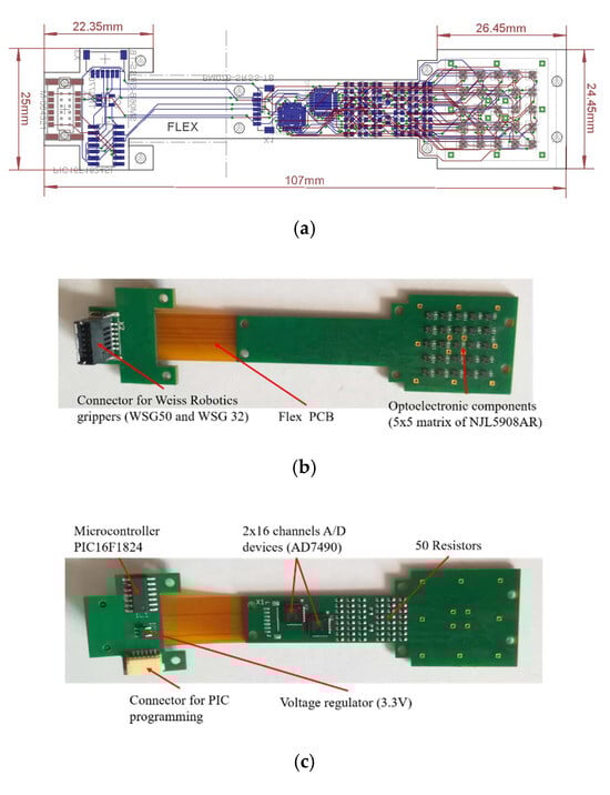
Figure 2.
The tactile sensor PCB: layout with dimensions (a) a top view (b) and a bottom view (c) with the components highlighted.
A mechanical structure constituted by the deformable layer and the rigid grid is connected above the PCB. The deformable layer is mainly made of white silicone with a domed top side and a square base, as shown by the picture in Figure 3a. The use of a non-axisymmetric shape implies, in presence of torsional moments applied to the deformable layer, the generation of the torsional warping effect, which is measurable by the tactile map and allows the reconstruction of the applied moment. Figure 3b shows the bottom side of the deformable layer, where there are the twenty-five empty cells, which present the ceilings (which in the final assembly are positioned in front of photo-reflectors) made of white silicone, while the walls among the taxels are black, to avoid cross-talk effects.
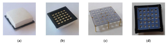
Figure 3.
Pictures of deformable layer and rigid grid: top view (a) and bottom view (b) of the deformable layer, grid with bonded pins (c) and deformable layer assembled with the grid (d).
According to the working principle, when external forces and/or moments are applied to the deformable layer, they produce vertical displacements of the white ceilings for all cells. The distances between the photo-reflectors and the white surfaces change, by producing variations of the reflected light and, accordingly, of the voltage signals measured by the PTs. The third component (i.e., the rigid grid) is necessary due to the electromechanical characteristic of the optical components. In particular, the NJL5908AR photo-reflector has a non-monotonic characteristic, which relates the measured voltage to the distance of a reflecting surface positioned in front of the component. As a consequence, the rigid grid has to ensure that the reflecting surface never reaches distances from the component that fall into the non-monotonic area. Moreover, the grid design foresees holes suitable for housing rigid pins. Figure 3c shows a grid assembled with the pins, which are bonded via a cyanoacrylate-based glue.
This assembled grid is then bonded to the deformable layer, by using the same glue, by obtaining the final mechanical cap reported in Figure 3d. The rigid pins that come out of the assembled cap are used to align the cells with the optical components on the PCB, thanks to the mechanical holes available on the board (see Figure 1). After the alignment, the same pins are used to mechanically connect the cap and the PCB, by soldering the rigid pins to the bottom side of the board (see Figure 2c).
The assembled sensor has been preliminary tested, by acquiring the voltages from the taxels from the on-board PIC, connected via a standard USB-serial cable to the PC. Figure 4 reports the voltages acquired from some of the sensor taxels. It shows that the voltage variations are sufficiently high and with low-noise to be directly using without any additional post-processing phase.
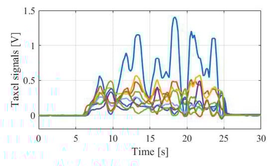
Figure 4.
Typical voltage signals acquired from some taxels of the assembled sensor.
3. Conclusions
This paper has presented the detailed design of a force/tactile sensor able to measure distributed contacts and estimate contact force and torsional moments to be used for robotic dexterous manipulation tasks. The mechanical interface of the device is a soft pad of silicone so as to adapt to different object shapes and hold high torsional moments. The sensitive part, based on optoelectronic technology, can be exploited not only to estimate the total contact wrench but also to detect the orientation of the contact surface essential to correctly detect friction force, a relevant quantity in any dexterous manipulation control algorithm.
Author Contributions
All authors contributed to the paper in the same way.
Funding
This work was partially supported by the European Commission’s H2020 Framework Programme under grant agreement no. 731590 (REFILLS project).
Conflicts of Interest
The authors declare no conflict of interest. The funders had no role in the design of the study; in the collection, analyses, or interpretation of data; in the writing of the manuscript, or in the decision to publish the results.
References
- Mittendorfer, P.; Lumelsky, V.J.; Dahiya, R.S.; Valle, M.; Cheng, G. Directions Toward Effective Utilization of Tactile Skin: A Review. IEEE Sensors J. 2013, 13, 4121–4138. [Google Scholar]
- De Maria, G.; Natale, C.; Pirozzi, S. Force/tactile sensor for robotic applications. Sensors Actuators A Phys. 2012, 175, 60–72. [Google Scholar] [CrossRef]
- Cirillo, A.; Cirillo, P.; De Maria, G.; Natale, C.; Pirozzi, S. Control of linear and rotational slippage based on six-axis force/tactile sensor. In Proceedings of the 2017 IEEE International Conference on Robotics and Automation (ICRA), Singapore, 29 May–3 June 2017; pp. 1587–1594. [Google Scholar]
Publisher’s Note: MDPI stays neutral with regard to jurisdictional claims in published maps and institutional affiliations. |
© 2019 by the authors. Licensee MDPI, Basel, Switzerland. This article is an open access article distributed under the terms and conditions of the Creative Commons Attribution (CC BY) license (https://creativecommons.org/licenses/by/4.0/).