Proceeding Paper

Three Lobes Plastic Optical Fiber Bending and Rotation Sensor †

by
Demetrio Sartiano
1,*,
Salvador Sales
1 and
Elena Torres Roca
2
1
Institute of telecommunications and multimedia applications (iTEAM), Universitat Politècnica de València, Camino de Vera, s/n 46022 Valencia, Spain
2
Textile Research Institute (AITEX), Plaza Emilio Sala, 1, 03801 Alcoy, Spain
*
Author to whom correspondence should be addressed.
Presented at 7th International Symposium on Sensor Science, Napoli, Italy, 9–11 May 2019.
Proceedings 2019, 15(1), 15; https://doi.org/10.3390/proceedings2019015015
Published: 9 July 2019
(This article belongs to the Proceedings of 7th International Symposium on Sensor Science)

Abstract

:
In this work a multiparameter plastic optical fiber (POF) sensor is presented. A three lobes POF consisting of polymethylmethacrylate (PMMA) core and a fluorinated polymer (FP) for the cladding was fabricated. The aim is to use a plastic fiber with non-circular shape to implement a bending direction and rotation sensor. The mode confinement in the plastic filament obtained with the extrusion process was simulated, and the effect of bending evaluated. The POF sensor is interrogated in transmission using an LED as light source and a charge-coupled device (CCD) to capture the light intensity distribution inside the core, and then analyze the changes when a bending or a rotation is applied.

1. Introduction

In recent years, fiber-based sensors have played an important role in many applications: in bridge security monitoring [1], biochemical sensing [2], gas concentration detection [3] and power system monitoring [4], due to their advantages, such as small size, immunity to electromagnetic interference, remote sensing capability and high sensitivity. Novel fiber sensors are mainly fabricated by innovating the structure of fiber grating or inscribing grating in special fibers instead of standard single mode fibers (SMF). These developments are focused on solving the problem of the cross-sensitivity between temperature and strain and on implementing multi parameters fiber sensors for new measurands. Baiou Guan et al. [5] utilized a superstructure FBG to achieve the simultaneous measurement of strain and temperature; Maoqing Chen et al. [6] combined a micro extrinsic Fabry-Perot interferometer with an etched FBG for the simultaneous measurement of strain and magnetic field. Yunhe Zhao et al. [7] used a UV laser to inscribe a tilted FBG in a few mode fiber (FMF), for the simultaneous measurement of directional curvature and temperature. Hangzhou Yang et al. [8] proposed a novel optical implement to realize the simultaneous measurement of refractive index (RI) and temperature. The sensor was based on an FBG inscribed in an FMF by a UV laser and a cladding-less structure made by a chemical etching technique. Multicore fibers (MCF) have been used also in sensing field, David Barrera et al. [9] inscribed tilted fiber Bragg grating (TFBG) in a seven-core fiber by an Argon-ion laser. The TFBG coupled light from the incident-guided mode not only to the cladding modes but also to the neighbor cores, and the interaction showed great sensitivity to the external environment. The optical sensor was used to measure strain, curvature direction and magnitude, and external RI. An alternative to the sensor implemented through the inscription of gratings in different types of fibers is given by the strongly coupled MCF: in [10] is reported a strain sensor implemented using an MCF with the cores placed closer to each other than in the common MCF fiber. This MCF was spliced on both sides with SMFs, one of them has a mirror at the end. The interference between two supermodes excited in the MCF, allows to obtain an interferometric strain sensor. In this work an optical fiber with non-circular shape was fabricated, with three lobes. Specifically, the fiber consists of a three lobes fiber core of PMMA with cladding. The filament was directly extruded from plastic pellets, and the trilobal shape was obtained using a customized shaping extrusion die. The three lobes shape of the fiber was conceived to implement a low-cost optical fiber sensor for bending direction and rotation. The bend direction sensing principle is based on the shift of the light modes that propagate in the three lobes fiber of the PMMA when the plastic filament is bent. The circular asymmetry of the fiber permits to retrieve the direction of the bending and the rotation angle. The sensor is interrogated in transmission using a red LED (645 nm) and a CCD placed in front of the fiber end. The paper is structured as follow: the first section is a brief presentation of the process used to fabricate the polymer fiber and the result of the preliminary simulations of the mode confinement in the obtained structure; the second section is concerned with presenting the experimental results obtained using the fabricated fiber; the conclusion and the future development are commented in the last section.

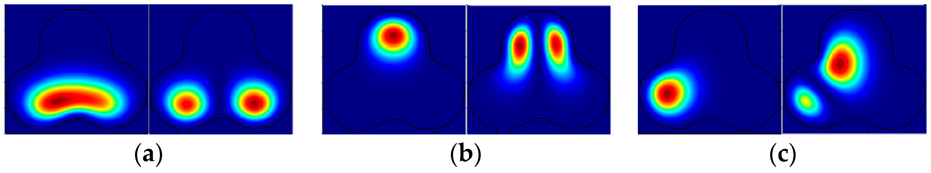
2. Fiber Fabrication and Simulation of the Sensor

The extrusion machine is presented schematically in Figure 1a. The two units (screw and heater bands) interact together to convey the polymeric material, melt the material, and then push it through the die. The screw rotates at a predetermined speed with the electric motor drive unit. Temperature controllers are connected to heating/cooling elements on the heater bands to maintain the temperature at the set-point temperatures. A custom shaping die was used to obtain a trilobal shape. The polymer filament was cooled down and collected with a rotating spool. The pressure and temperature of the material, as well as the temperature and velocity of the cooling process, influence the crystallization process. The fabrication parameters were swept, and various samples were fabricated and tested to find the set of parameters to minimize the optical losses. The facet of the three lobes fiber was captured with a microscope (Figure 1b), processed and imported in Lumerical software (Vancouver, BC, Canada). Simulation of the mode confinement was used to calculate the electric field intensity of the lowest order modes. The modes guided in the straight and bent fiber were computed. In Figure 1c is shown the electric field intensity of the lowest order fiber mode simulated in the straight fiber.
As observed in previous calculation and simulation on bent fibers, bending tended to distort the fiber modes, and caused them to shift from the center of curvature [11]. It was possible to simulate the mode field in the bent fibers with Lumerical software. The electric field intensity for the lowest order modes and three direction of bending was simulated, in Figure 2 are shown the results.

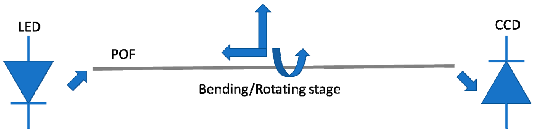
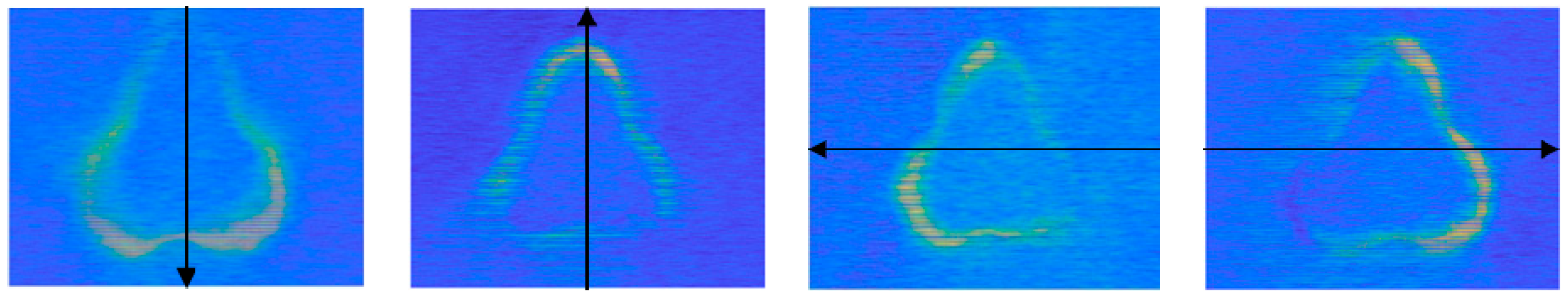
3. Experimental Results

The simulations show that the modes guided in the bent trilobal fiber shift far from the center of the curvature. A setup was used to interrogate the three lobes fiber in transmission. The POF was fixed to a translational stage to bend and rotate it and observe how the light intensity change inside the core. Sensors based on intensity variation represent one of the first detection schemes used in optical fiber sensors. In terms of operating principle and instrumentation, it may be considered the simplest method. In general, experimental setups include a light source, the optical fiber and a photodetector or an optical spectrum analyzer. Commercially, several solutions for miniaturized solid-state sources and photodetectors are available, allowing the design and development of robust and portable acquisition systems. This is a suitable solution for engineering applications, where the accuracy in the power signal measuring is not critical. The advantages of this measurement method are the ease of implementation, good price/quality ratio and simplicity in signal processing [12]. The plastic fiber was interrogated in transmission using an LED emitting at 645 nm (IF-E96 from Industrial Fiberoptics, Tempe, AZ, USA), and a CCD camera (Figure 3).
The fiber was fixed in front of the camera and a bending was applied using a translational stage, two images were captured before and after the bending and then compared using Matlab software. In Figure 4 are reported four images obtained for bending orientation along x and y axis (black arrows). A light intensity variation is clearly observable in the external part of the fiber, due to the shift of the fiber modes due to the bending applied.
The fiber was placed in a rotating clamp and rotated from 0° to 50° degrees with step of 10° degrees (Figure 5). Intensity-based automatic image registration algorithm was used to retrieve the rotation angle of the fiber through the images acquired with the camera. The obtained angles retrieved from the images are reported in Figure 5, under the correspondent image.

4. Conclusions and Future Development

In this work is presented the fabrication, simulation and experimental validation of a bending and rotation sensor employing a three lobes plastic fiber. Extrusion and a custom shaping die were employed to fabricate a PMMA filament. The extrusion process was optimized to reach as low optical losses as possible. The modes guided in the obtained polymeric fiber were simulated using Lumerical software. The electric field shift due to bending was also addressed with the simulations. This shift was monitored, interrogating the fiber in transmission. The circular asymmetry of the fabricated fiber permits to retrieve the direction of bending in space and the rotation angle, processing the images with intensity-based image registration algorithm.

Author Contributions

D.S. and S.S. conceived and design the plastic fiber and the interrogation system; E.T.R. fabricated the plastic optical; D.S. processed the data and wrote the paper.

Funding

This research was supported by FINESSE project, funded by the European Union’s Horizon 2020 research and innovation program under the Marie Sklodowska-Curie Action grant agreement n° 722509.

Conflicts of Interest

The authors declare no conflict of interest.

References

  1. Maaskant, R.; Alavie, T.; Measures, R.; Tadros, G.; Rizkalla, S.; Guha-Thakurta, A. Fiber-optic Bragg grating sensors for bridge monitoring. Cem. Concr. Compos. 1997, 19, 21–33. [Google Scholar] [CrossRef]
  2. Baldini, F.; Brenci, M.; Chiavaioli, F.; Giannetti, A.; Trono, C. Optical fibre gratings as tools for chemical and biochemical sensing. Anal. Bioanal. Chem. 2012, 402, 109–116. [Google Scholar] [CrossRef] [PubMed]
  3. Qin, X.; Feng, W.; Yang, X.; Wei, J.; Huang, G. Molybdenum sulfide/citric acid composite membrane-coated long period fiber grating sensor for measuring trace hydrogen sulfide gas. Sensors Actuators B Chem. 2018, 272, 60–68. [Google Scholar] [CrossRef]
  4. Kim, H.-J.; Park, H.-J.; Song, M.-H. A Quasi-Distributed Fiber-Optic Sensor System using an InGaAs PD Array and FBG Sensors for the Safety Monitoring of Electric Power Systems. J. Korean Inst. Illum. Electr. Install. Eng. 2010, 24, 86–91. [Google Scholar]
  5. Guan, B.-O.; Tam, H.-Y.; Tao, X.-M.; Dong, X.-Y. Simultaneous strain and temperature measurement using a superstructure fiber Bragg grating. IEEE Photon- Technol. Lett. 2000, 12, 675–677. [Google Scholar] [CrossRef]
  6. Chen, M.-Q.; Zhao, Y.; Lv, R.-Q.; Xia, F. Hybrid MEFPI/FBG sensor for simultaneous measurement of strain and magnetic field. Opt. Fiber Technol. 2017, 39, 32–36. [Google Scholar] [CrossRef]
  7. Zhao, Y.; Wang, C.; Yin, G.; Jiang, B.; Zhou, K.; Mou, C.; Liu, Y.; Zhang, L.; Wang, T. Simultaneous directional curvature and temperature sensor based on a tilted few-mode fiber Bragg grating. Appl. Opt. 2018, 57, 1671–1678. [Google Scholar] [CrossRef] [PubMed]
  8. Yang, H.Z.; Ali, M.M.; Islam, M.R.; Lim, K.-S.; Gunawardena, D.S.; Ahmad, H. Cladless few mode fiber grating sensor for simultaneous refractive index and temperature measurement. Sensors Actuators A: Phys. 2015, 228, 62–68. [Google Scholar] [CrossRef]
  9. Barrera, D.; Madrigal, J.; Sales, S. Tilted fiber Bragg gratings in multicore optical fibers for optical sensing. Opt. Lett. 2017, 42, 1460. [Google Scholar] [CrossRef] [PubMed]
  10. Villatoro, J.; Arrizabalaga, O.; Durana, G.; De Ocáriz, I.S.; Antonio-Lopez, E.; Zubia, J.; Schülzgen, A.; Amezcua-Correa, R. Accurate strain sensing based on super-mode interference in strongly coupled multi-core optical fibres. Sci. Rep. 2017, 7, 4451. [Google Scholar] [CrossRef] [PubMed]
  11. Schermer, R.T.; Cole, J.H. Improved Bend Loss Formula Verified for Optical Fiber by Simulation and Experiment. IEEE J. Quantum Electron. 2007, 43, 899–909. [Google Scholar] [CrossRef]
  12. Sartiano, D.; Sales, S. Low Cost Plastic Optical Fiber Pressure Sensor Embedded in Mattress for Vital Signal Monitoring. Sensors 2017, 17, 2900. [Google Scholar] [CrossRef] [PubMed]
Figure 1. (a) Extrusion machineries and process presented schematically: screw velocity, cool down temperature and velocity of the wind-up machine were optimized to find the best performance in terms of optical losses. (b) Facet of the three lobes plastic optical fiber. (c) Electric field intensity of the lowest order fiber mode simulated.
Proceedings 15 00015 g001
Figure 2. Electric field intensity of the two lowest order modes calculated in the imported three lobes structure for bending with curvature center placed: on the upper side of the fiber (a); on the lower side of the fiber (b); on the right side of the fiber (c).
Proceedings 15 00015 g002
Figure 3. Schematic representation of the experimental setup.
Proceedings 15 00015 g003
Figure 4. Images collected with the CCD camera after bending the three lobes plastic fiber, the black arrows indicate the direction of the curvature applied.
Proceedings 15 00015 g004
Figure 5. Image capture with the CCD camera of the POF with rotation. The circular asymmetry permits to observe the rotation of the fiber core and retrieve the rotation angles (reported below) using an intensity-based automatic image registration algorithm.
Proceedings 15 00015 g005
Publisher’s Note: MDPI stays neutral with regard to jurisdictional claims in published maps and institutional affiliations.

