1. Introduction
It is becoming increasingly important to investigate the occurrence and progression of fatigue cracks as steel bridges age. Traditionally, magnetic particle inspection has been widely used to inspect steel bridges for cracks, but this requires getting close to the object being inspected. Furthermore, the object is often located at a high altitude, which requires time and money for preparations such as setting up scaffolding and arranging a high-altitude work vehicle, and also requires measures to address the dangers of working at height. Infrared thermography can remotely measure the temperature required for crack detection without contact. If cracks are present in a structure, the stress concentration area at the tip of the crack can be detected by thermoelastic stress analysis.
In this system, the weight and passing volume of normal automobiles are used as the dynamic load applied to the structure. The timing and speed of passing automobiles are random. Because the temperature fluctuations used in thermoelastic stress analysis are small, there is a possibility that the reflected components from heat sources in the surrounding environment may be mistaken for temperature fluctuations caused by the passing of a vehicle. Therefore, a monitoring system was developed that obtains displacement information from high-resolution visible images acquired in synchronization with infrared thermography, detects passing vehicles, identifies the timing of changes caused by the passing of a vehicle, and saves measurement data only when a vehicle passes.
In the monitoring system, the synchronous output signal from the infrared thermography (A6751 (Teledyne FLIR LLC., Wilsonville, OR, USA)) is used as the synchronous input signal for the visible camera (acA1920–150um (Basler AG, Ahrensburg, Deutschland)). The measurement data for each frame from the infrared thermography and visible camera is stored in a ring buffer, and after a certain amount of time has passed since the displacement amount calculated from the visible image data exceeded a threshold, the data stored in the ring buffer is saved in storage, making it possible to save the measurement data before and after the time it is subjected to weighting due to vehicles randomly passing by (
Figure 1).
2. Background
The load of a vehicle passing over a bridge causes a deflection of the bridge, which causes an apparent temperature change in the temperature distribution measured by infrared thermography. The amount of deflection of the bridge is calculated from images taken by a visible camera synchronized with the infrared thermography, and the deflection of the bridge on the infrared thermography is converted into a movement to correct it, thereby suppressing the apparent temperature change and improving accuracy [
1].
3. Analysis
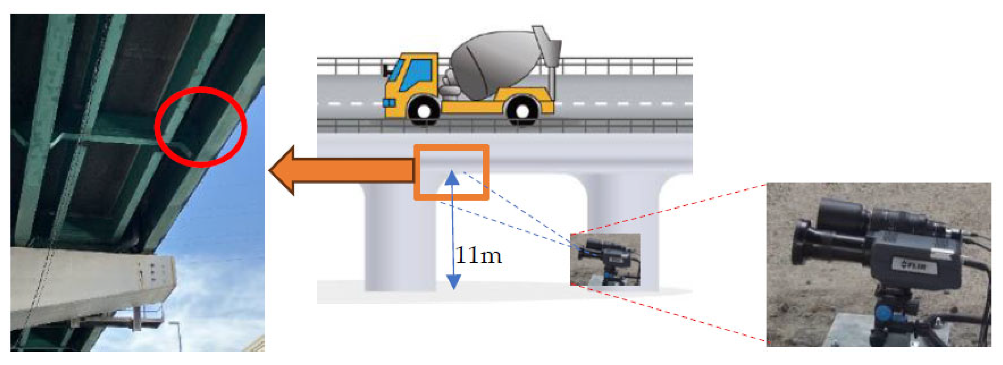
Figure 2 shows measurement Composition. The floor slab bottom surface is 11 m. and the area where the actual bridge was measured (red circle) was approximately 15 m away from the camera, and a lens with a focal length of 200 mm was used.
The measured infrared thermography image and visible image are shown in
Figure 3.
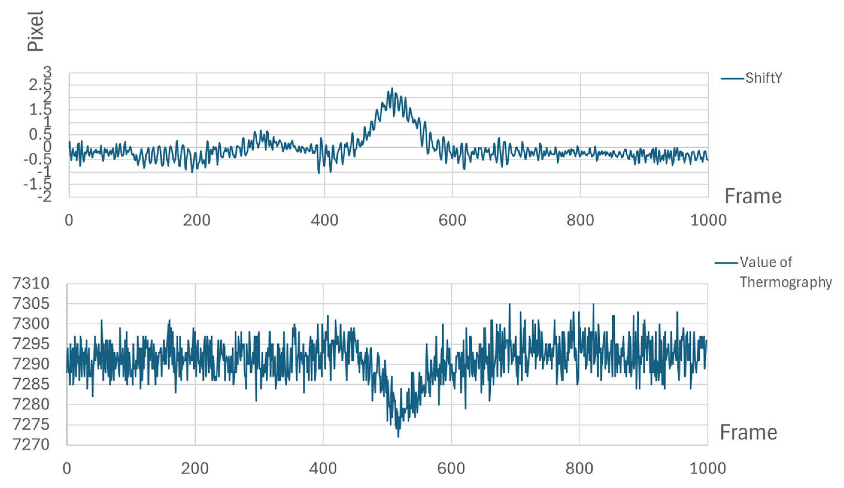
Figure 4 shows the changes in bridge deflection displacement and temperature over time during measurement.
The deflection displacement of the bridge was corrected, and the changes in the temperature distribution image were analyzed using autocorrelation lock-in to calculate the stress distribution.
In the gray display, the area where stress is concentrated at the tip of the crack is bright, and in the color display it is displayed in red (
Figure 5).
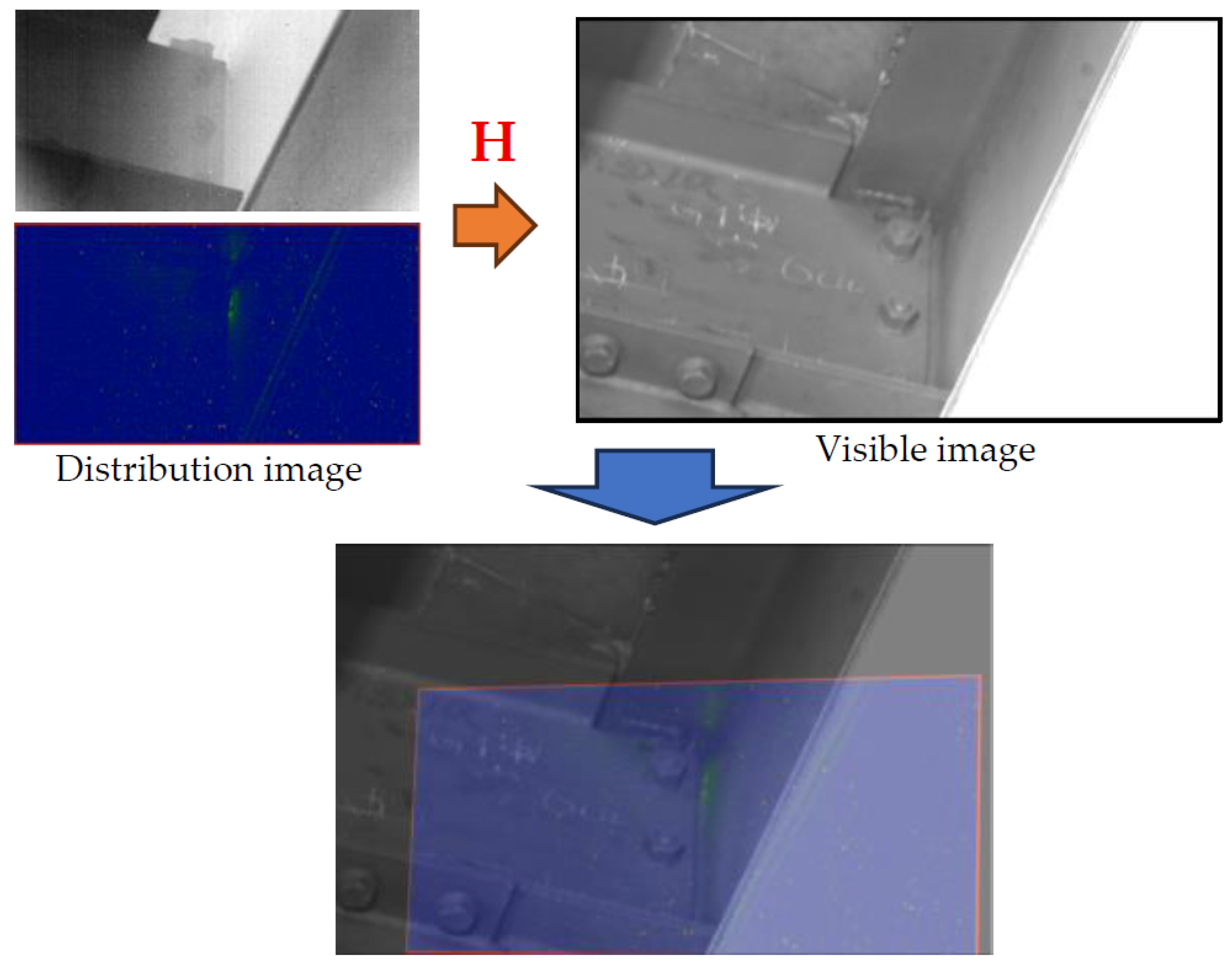
In addition, a homography matrix (
H) was calculated from four points in the visible light image and the infrared image (
Figure 6). By mapping the stress distribution image onto a visible image with the matrix (
H), it becomes easier to identify the tip of a crack in an actual bridge (
Figure 7).
4. Conclusions
When this system was applied to an actual steel bridge, it was found that displacement measurement and position correction using a visible image camera were effective in improving measurement efficiency and accuracy in TSA measurements that utilize the load of randomly passing vehicles.
Author Contributions
M.H.: Conceptualization, methodology, investigation, data curation, writing—original draft preparation; T.S.: data curation, writing—review and editing; D.S.: methodology, data curation, project administration, writing—review and editing; Y.U.: project administration, writing—review and editing. All authors have read and agreed to the published version of the manuscript.
Funding
This research received no external funding.
Institutional Review Board Statement
Not applicable.
Informed Consent Statement
Not applicable.
Data Availability Statement
Data will be made available upon request.
Conflicts of Interest
Author Mitsuhiro Hori and Yuji Uchida are employed by NEXCO WEST Innovations Company Limited. The remaining authors declare that the research was conducted in the absence of any commercial or financial relationships that could be construed as a potential conflict of interest.
Reference
- Uchida, Y.; Shiozawa, D.; Hori, M.; Kobayashi, K. Advanced Technique for Thermoelastic Stress Analysis and Dissipation Energy Evaluation Via Visible-Infrared Synchronous Measurement. Exp. Mech. 2022, 62, 459–470. [Google Scholar] [CrossRef]
| Disclaimer/Publisher’s Note: The statements, opinions and data contained in all publications are solely those of the individual author(s) and contributor(s) and not of MDPI and/or the editor(s). MDPI and/or the editor(s) disclaim responsibility for any injury to people or property resulting from any ideas, methods, instructions or products referred to in the content. |
© 2025 by the authors. Licensee MDPI, Basel, Switzerland. This article is an open access article distributed under the terms and conditions of the Creative Commons Attribution (CC BY) license (https://creativecommons.org/licenses/by/4.0/).


