Abstract
This study presents a comprehensive computational fluid dynamics (CFD) analysis of airflow in double Schwarz-D Triply Periodic Minimal Surface (TPMS) structures under laminar steady-flow conditions. The pressure drop characteristics of these structures are investigated using representative elementary volume (REV)-scale CFD simulations. Two porosities, 58% and 80%, are analyzed to evaluate the influence of porosity on the flow characteristics and pressure drop. The results reveal that an increase in porosity significantly affects the hydraulic Reynolds number. For the 58% porosity structure, laminar flow is observed at hydraulic Reynolds numbers of 50 or lower, whereas the 80% porosity structure maintains laminar flow at Reynolds numbers up to 180. These findings provide valuable insights into the design and optimization of double Schwarz-D TPMS structures for engineering applications, particularly in scenarios requiring efficient fluid transport with controlled pressure drops.
1. Introduction
Triply Periodic Minimal Surfaces (TPMSs) have received significant attention in engineering due to their unique geometric properties, which offer a high surface-area-to-volume ratio and adjustable porosity. The advent of advanced 3D printing technologies has further revolutionized the application of TPMSs, enabling the precise fabrication [1] of these complex structures for mechanically optimized designs. This capability expands their use in diverse fields, including chemical engineering and biomedical engineering. The double Schwarz-D structure, part of the TPMS class, is characterized by its high surface-area-to-volume ratio.
In our previous study, we conducted a detailed analysis of fluid flow through Schwarz-D TPMS structures using CFD simulations, focusing on pressure drop characteristics in both full-scale and representative elementary volume (REV)-scale setups. The results demonstrated strong agreement between simulation outcomes and experimentally measured pressure drops. Additionally, the REV-scale simulations showed good agreement with experimental data from the literature and full-scale CFD results, highlighting the effectiveness of REV-scale simulations for analyzing fluid dynamics in TPMS structures [2,3].
Building on these findings, the present study further explores airflow behavior within a double Schwarz-D structure using only REV-scale simulations. This study aims to predict the pressure drop and provide insights into the flow dynamics of the double Schwarz-D structure.
2. Methodology
The flow characteristics within double Schwarz-D TPMS structures were investigated through single-phase CFD simulations. The geometry of the double Schwarz-D TPMS structure was generated using the open-source software Lattice_Karak v1.0 [4], which specializes in creating TPMS lattice structures. The geometry was exported as an STL file and subsequently imported into the commercial software STAR-CCM+ (version 2302, Siemens Product Lifecycle Management Software Inc., Plano, TX, USA), where all CFD simulations were performed. In Lattice_Karak, the double Schwarz-D TPMS structure was created using the implicit method, which involves a single-valued function of three variables. The surface of the structure corresponds to the locus of points where the function equals a constant value. This zero-valued surface, also referred to as a zero set or level set, defines the interface regions within the space [4]. Through the use of two different level-set values, −0.3 and +0.3, structures with porosities of 80% and 58%, respectively, were generated.
The CFD simulations were carried out at the REV scale, focusing on a single unit cell with periodic boundary conditions to utilize the repetitive nature of the structure. The primary outcome of the CFD simulations was the pressure drop across the double Schwarz-D structure, which is a key parameter for analysis.
2.1. CFD Simulation Setup
The setup for the REV-scale simulation of single-phase flow through a double Schwarz-D TPMS structure, featuring 58% porosity and a unit cell size (UCZ) of 3 mm, is shown in Figure 1a. A rectangular computational domain was designed with a length equal to five times the UCZ and a width the same as the UCZ, as illustrated in Figure 1a. The double Schwarz-D structure was subtracted from this rectangular domain to define the flow region used for the CFD simulation.
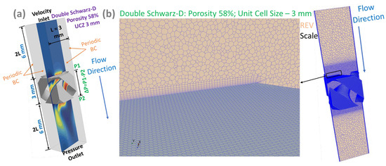
Figure 1.
(a) CFD setup for representative elementary volume (REV) scale; (b) REV-scale polyhedral meshing with prism layers.
To determine the pressure drop after completing the CFD simulation, two plane surfaces, P1 and P2, were created as depicted in Figure 1a, with a distance of 3 mm between them. The pressure drop (ΔP = P1 − P2) was calculated by generating surface-average reports for planes P1 and P2 during the post-processing of the simulation. This configuration was implemented for the CFD simulations of the 58% porosity case. For the 80% porosity case, the length of the rectangular computational domain was extended to six times the UCZ, compared to five times the UCZ in the 58% porosity case. This extension was necessary due to the observation of air recirculation near the outlet, which indicated an insufficient domain length for outflow boundary conditions. As illustrated in Figure 1a, periodic boundary conditions were applied to all four side walls in the REV setup, while velocity-inlet and pressure-outlet boundary conditions were implemented at the inlet and outlet, respectively. The simulations were performed using air with a constant density, flowing through the solid structures under laminar steady-state conditions.
As depicted in Figure 1b, a polyhedral mesh for the REV-scale setup was generated through STAR-CCM+’s automated meshing tool after defining the flow domain. A global base mesh size of 0.3 mm was selected to ensure sufficient resolution for capturing key flow features. To resolve near-wall regions and accurately model boundary layer effects, nine prism layers were applied, with a total thickness equivalent to 20% of the base size. Additionally, a volumetric control mesh was applied around the double Schwarz-D structure, with a base size set to 10% of the global mesh size, enabling better resolution of the complex flow features within the structure. The final mesh contained roughly 3.7 million polyhedral cells for the simulation case with 58% porosity.
Pre-processing, simulation and post-processing were carried out using Simcenter STAR-CCM+ (version 2302, Siemens Product Lifecycle Management Software Inc., Plano, TX, USA). The numerical simulations were executed on a parallel computing system at the Max Planck Research Institute in Magdeburg, featuring 11th Gen. Intel Core i7–11700 processors operating at 2.50 GHz, each equipped with 64 GB RAM.
2.2. Flow Properties
The hydraulic diameter is used to generalize the length scale, avoiding reliance on specific geometric features. It is determined using the total surface area and the porosity of the structure.
where is the hydraulic diameter, is the porosity, is the total volume and is the wetted surface area. The Reynolds number is defined using the hydraulic diameter as
where is the Reynolds number based on the hydraulic diameter, is the fluid density, is the superficial velocity and is the dynamic viscosity.
3. Results and Discussion
In the CFD simulation of airflow through a double Schwarz-D TPMS structure, the laminar steady model demonstrates good convergence for continuity residuals below 10−6 in a structure with 58% porosity, up to a Reynolds number of 50. However, at Reynolds numbers higher than 50, the laminar steady model fails to converge, exhibiting oscillatory residuals. This behavior suggests that for Reynolds numbers exceeding 50, the flow becomes unsteady, and a laminar unsteady model is required to accurately capture the flow behavior. For a structure with 80% porosity, the laminar steady model maintains good convergence (10−6) up to a Reynolds number of 180. Beyond this threshold, the residuals become oscillatory and fail to converge, indicating the onset of unsteady flow behavior.
Figure 2 shows the relationship between the pressure drop and hydraulic Reynolds number ) for two different porosity configurations (58% and 80%) of a double Schwarz-D TPMS structure under laminar steady-flow conditions. The lower-porosity structure (58%) exhibits significantly higher pressure drops for the same due to increased flow resistance arising from a more compact and restrictive pore network. Conversely, the 80% porosity structure shows a more gradual increase in pressure drop with , suggesting reduced airflow resistance due to the larger void fraction facilitating smoother airflow. These findings highlight the critical role of porosity in controlling pressure losses.
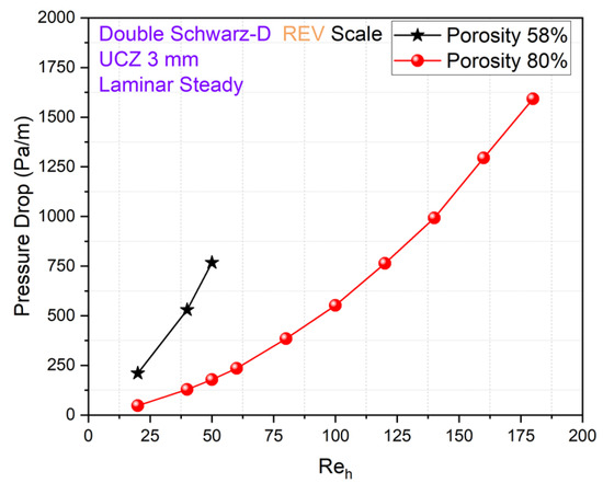
Figure 2.
Comparison of pressure drop at 58 and 80% porosity of double Schwarz-D structure.
4. Conclusions
The findings of this study demonstrate that while the laminar steady model works well for predictions of pressure drop for Reynolds numbers up to approximately 50 for the 58% porosity case, the limit increases up to 180 for the 80% porosity case. The lower-porosity structure (58%) experiences a substantially higher pressure drop due to increased flow restriction, whereas the higher-porosity structure (80%) demonstrates a more gradual increase in pressure drop, indicating reduced airflow resistance. These findings are crucial for designing optimized TPMS-based porous structures in engineering applications where pressure drop and permeability must be balanced for enhanced performance and efficiency.
Author Contributions
Conceptualization, K.V., G.J. and K.S.; methodology, K.V., D.T., G.J. and K.S.; software, K.V. and G.J.; investigation, K.V. and G.J.; resources, K.V., D.T., G.J. and K.S.; writing—original draft preparation, K.V.; writing—review and editing, K.V., D.T., G.J. and K.S.; supervision, D.T., G.J. and K.S.; project administration, G.J. and K.S.; funding acquisition, K.S. All authors have read and agreed to the published version of the manuscript.
Funding
This research is supported by the European Regional Development Fund (ERDF) and the International Max Planck Research School for Advanced Methods in Process and Systems Engineering (IMPRS ProEng), Magdeburg, Germany.
Institutional Review Board Statement
Not applicable.
Informed Consent Statement
Not applicable.
Data Availability Statement
The data are presented in this paper in the form of graphs.
Acknowledgments
This research was supported by the International Max Planck Research School for Advanced Methods in Process and Systems Engineering (IMPRS ProEng), Magdeburg, Germany.
Conflicts of Interest
The authors declare no conflicts of interest.
References
- Gado, M.G.; Al-Ketan, O.; Aziz, M.; Al-Rub, R.A.; Ookawara, S. Triply Periodic Minimal Surface Structures: Design, Fabrication, 3D Printing Techniques, State-of-the-Art Studies, and Prospective Thermal Applications for Efficient Energy Utilization. Energy Technol. 2024, 12, 2301287. [Google Scholar] [CrossRef]
- Vhora, K.; Thévenin, D.; Janiga, G.; Sundmacher, K. CFD Analysis of the Flow in Schwarz-D TPMS Structures for Engineering Applications. Chem. Ing. Tech. 2024, 96, 1683–1696. [Google Scholar] [CrossRef]
- Vhora, K.; Neeraj, T.; Thévenin, D.; Janiga, G.; Sundmacher, K. Investigating Fluid Flow Dynamics in Triply Periodic Minimal Surfaces (TPMS) Structures Using CFD Simulation. In Computer Aided Chemical Engineering, Proceedings of the 34th European Symposium on Computer Aided Process Engineering/15th International Symposium on Process Systems Engineering, Florence, Italy, 2–6 June 2024; Manenti, F., Reklaitis, G.V., Eds.; Elsevier: Amsterdam, The Netherlands, 2025; Volume 53, pp. 709–714. [Google Scholar] [CrossRef]
- Raju, S.K.K.; Onkar, P.S. Lattice_Karak: Lattice Structure Generator for Tissue Engineering, Lightweighting and Heat Exchanger Applications. Softw. Impacts 2022, 14, 100425. [Google Scholar] [CrossRef]
Disclaimer/Publisher’s Note: The statements, opinions and data contained in all publications are solely those of the individual author(s) and contributor(s) and not of MDPI and/or the editor(s). MDPI and/or the editor(s) disclaim responsibility for any injury to people or property resulting from any ideas, methods, instructions or products referred to in the content. |
© 2025 by the authors. Licensee MDPI, Basel, Switzerland. This article is an open access article distributed under the terms and conditions of the Creative Commons Attribution (CC BY) license (https://creativecommons.org/licenses/by/4.0/).