1. Introduction
Machine milking was developed with the aim of reducing the milking time and human labour [
1]. A relatively newer concept is taking into account a dynamic control strategy, based on adjusting the vacuum level in accordance with the milk flow rate. There are at least three reasons for this solution:
Teat tissue stress is most severe when the milk flow rate is low [
1];
Lower values of vacuum decrease milk flow rate and increase milking time [
2]; thus, increasing the vacuum level when the milk flow rate is high has the potential to shorten the milking time;
When there is no milk flow, the vacuum beneath the teat (claw vacuum) is similar to the full system vacuum level, but it decreases when milk is transported through the milk tubes; the vacuum drop value depends on the technical characteristics of the milking system and increases with increasing milk flow rate [
3]. Consequently, the teat is exposed to full system vacuum at the start and end of milking, when lower values of the milk flow rate are recorded.
All these considerations led to a logical conclusion: system vacuum should be lower when the milk flow rate is low and should be increased when the milk flow rate increases.
If the electric motor that drives the vacuum pump is controlled by the means of a variable frequency drive (VFD), the vacuum level is maintained constant by modifying the speed of the vacuum pump. In a study conducted by Pazzona [
4], energy savings between 24 and 87% were reported when this method was used. Based on this idea, the results of dry tests regarding vacuum regulation by controlling the pump speed using a VFD were presented in a previous paper [
5].
In the present investigation wet tests (using water instead of milk) were performed in order to tune the PID controller which drives the VFD; then, the virtual instrument built using the LabVIEW environment was adapted in order to regulate the vacuum level as a function of the flow rate (lower vacuum when the flow rate was low and an increased vacuum when the flow rate increases), thus aiming to compensate for the vacuum drop due to the liquid being moved through the milk tube.
2. Materials and Methods
The tests were performed with a bucket milking machine, originally equipped with a valve and a spring-type vacuum regulator. The vacuum pump has a theoretical flow rate of 4.38·10−3 m3 s−1 (262 L/min) at a speed of 1350 min−1. A BRK type pneumatic pulsator was used to achieve the liner pulsation (65:35 pulsation ratio; 60 pulsation/min); the teacups were equipped with Boumatic R-1CX type round barrel-shaped liners. The volume of the claw was 23 cm3, and the overall length of the long milk tube was 2 m.
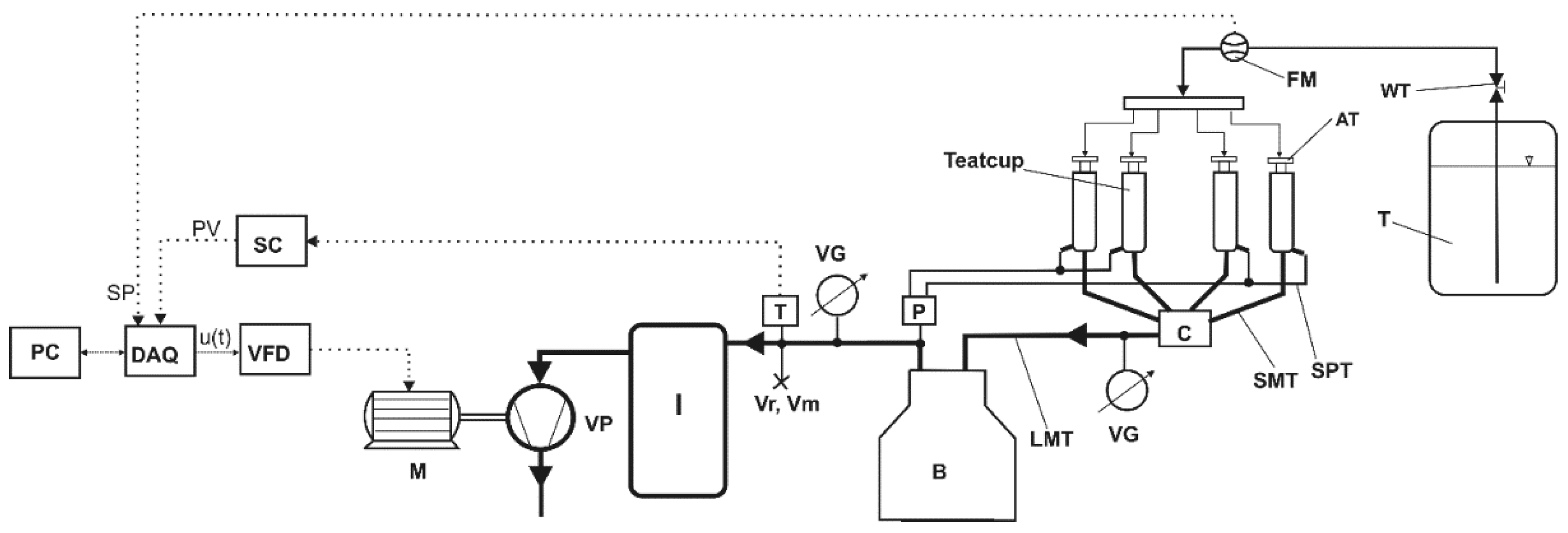
The initial milking system was modified in order to allow the control of the electric motor driving the vacuum pump by means of a VFD and a PID controller; thus, a capacity-controlled vacuum pump was obtained. The equipment (
Figure 1) was based on the one previously developed [
5], to which a section for performing wet tests was added. The artificial teats (AT) were fed with water from the water tank (T) by means of an electronic rotating vane flowmeter (FM), type Yf-S201. The water tap (WT) was used to modify the flow rate. The signal from the flowmeter was fed into the DAQ board, and its frequency was measured; the frequency was then converted into flow rate.
A Smartec SPD015AAsil (SMARTEC BV, Breda, The Netherlands) absolute pressure sensor (T) was used to monitor the vacuum in the permanent vacuum line in order to provide the signal for the DAQ board (process variable, PV). The pressure sensor was positioned at point Vr/Vm, as defined by the ISO 3918 standard [
6].
The data acquisition board was USB 6009 (National Instruments), with a sample rate of 48 ksamples/s, four differential analogue input channels, and two analogue output channels. The variable frequency drive unit was VFD 007M43B (0.7 kW maximum power of the electric motor) [
7].
The PID controller was built using the PID control toolbox from LabVIEW 7.1 (National Instruments, Austin, TX, USA), and a virtual instrument was created in order to provide the control signal to the VFD. The flow rate threshold reference (TR) was set at 1.94 L/min; the setpoint (SP) of the PID controller (desired vacuum level) was defined taking into account the flow rate, as follows:
If the flow rate was lower than TR, then SP = 0.42 bar;
If the flow rate was higher than TR, then SP = 0.45 bar.
The PID controller output is given by the relation [
8]:
where the error signal is
e(
t) =
SP-PV,
KP is the proportional gain,
Ti is the integral time, and
Td is the derivative time.
3. Results and Discussion
The tuning of the PID controller when the system was operated with water as a working fluid was imposed by the fact that the liner opening and closure in the absence of milk flow causes only minimal vacuum fluctuations; larger variations are to be expected when liquid is circulated through the lines [
9].
The PID controller was tuned using the Ziegler–Nichols tuning rules for the frequency response method [
10], with the system operating in wet mode, using water as a working fluid. The PID gain and times were as follows: proportional gain
KP = 23.6; integral time
Ti = 11 s; and derivative time
Td = 2.8 s.
The system was tested in order to verify vacuum stability; the test was performed for a flow rate of 4.5 L/min, and the desired system vacuum (SP) was set at 45 kPa (0.42 bar) and 42 kPa (0.42 bar), respectively. The vacuum fluctuations did not exceed ±1.5 kPa with respect to the desired value of the system vacuum, which within the acceptable range of ±2kPa imposed by the ISO 5707 standard [
11].
The tests of the milking machine were conducted in the following manner:
The milking system was turned on, and the flow rate was set below the flow rate threshold (FT) value;
The recording of the system response for the low flow rate regime was started after the vacuum level had reached the desired value of 42 kPa;
After 60 to 70 s, the flow rate was increased above the FT value, and the high flow rate regime was maintained for 1.5 to 2 min.
The flow rate threshold (FT) between the low flow rate regime and high flow rate regime was set to 1.94 L/min for all the variants, based on the value suggested by Reinemann et al. [
1]. The value of the high flow rate was chosen taking into account the specifications of the ISO 5707 standard [
11], which defines peak flow rates between 3 L/min (low productivity cows) and 5 L/min (high productivity cows).
The experimental data seem to suggest that, when the system was switched from the high flow rate to the low flow rate, significantly higher vacuum fluctuations around the set value (42 kPa) were recorded for high flow rates than for lower ones; as a matter of fact, very low vacuum fluctuations were recorded when the flow rate was set to zero by completely closing the water tap (WT,
Figure 1).
The recordings of the system response confirmed the previous results regarding vacuum stability, as vacuum fluctuations deed not exceed the imposed limit of ±2 kPa relative to the nominal vacuum [
12]; the standard deviation of the vacuum level was comprised between 0.067 kPa and 1.436 kPa (while the relative standard deviation of the mean was comprised between 0.002% and 0.05%, with reference to the mean vacuum level, depending on the value of the flow rate). The effect of liquid flow (in wet tests) over the vacuum fluctuations was confirmed by the fact that, in previous dry tests, the standard error was 0.194 kPa for a vacuum level of 40 kPa and 0.186 kPa for a vacuum level of 45 kPa [
5].
Taking into account that the average frequency of the vacuum fluctuations (around the SP) recorded when the flow rate dropped from high to low was comprised between 0.07 Hz and 0.072 Hz (4.2–4.35 cycles/min), it was clear that they were produced by the inertia of the column of liquid into the milk line and not by the pulsator of the system, as the pulsation rate was 60 cycle/min. Other authors [
13] also mention the inertia and resistance associated with liquid flow to be the cause of vacuum variations.
The statistical analysis of experimental data has shown that the average system response time was 9 s. These results are consistent with the findings of other authors [
4], who have reported an increase in the system response time when the vacuum level was regulated by the means of variable speed drives.
In order to reduce the vacuum fluctuations, the original claw of the installation and the test were repeated. For the same conditions, the standard error of the vacuum level was comprised between 0.067 and 1.436 kPa for the initial claw and between 0.134 and 0.288 kPa for the larger claw. The system response time to flow rate increase and decrease (in terms of vacuum level) was 8 s.
4. Conclusions
In this paper, the reliability of a milking system with a flow-controlled vacuum was assessed. It was concluded that vacuum fluctuations did not exceed the ±2k Pa limit imposed by the standard. When the original claw of the milking system was replaced with a larger one, lower vacuum fluctuations were registered.
The average system response time to flow rate change was 9 s when the original claw was used, and decreased by one second when the system was equipped with a larger claw.
The experimental tests confirmed the viability of the flow-controlled vacuum concept. Further development of the concept should take into account the hardware and software integration of the virtual instrument into an electronic control unit, independent of the specialized LabView environment.
Author Contributions
Conceptualization, R.R. and P.C.; methodology, P.C.; software, R.R. and P.C.; validation, R.R., P.C. and V.V.; investigation, R.R. and V.V.; writing—original draft preparation, R.R.; writing—review and editing, P.C.; supervision, R.R. All authors have read and agreed to the published version of the manuscript.
Funding
This research received no external funding.
Institutional Review Board Statement
Not applicable.
Informed Consent Statement
Not applicable.
Data Availability Statement
Conflicts of Interest
The authors declare no conflicts of interest.
Abbreviations
The following abbreviations are used in this manuscript:
| VFD | Variable frequency drive |
| AT | Artificial teats |
| FM | Flowmeter |
| WT | Water tap |
| TR | Threshold reference |
| SP | Setpoint |
| FT | Flow rate threshold |
References
- Reinemann, D.; van der Borne, B.; Horgeveen, H.; Wiedemann, M.; Paulrud, C. Effects of flow-controlled vacuum on milking performance and teat condition in a rotary milking parlor. J. Dairy Sci. 2020, 104, 6820–6831. [Google Scholar] [CrossRef] [PubMed]
- O’Callaghan, E.; Gleeson, D. A note on the effects of teat-end vacuum on milking characteristics. Ir. J. Agric. Food Res. 2004, 43, 265–269. Available online: http://www.jstor.org/stable/25562524 (accessed on 15 May 2023).
- Besier, J.; Bruckmaier, R. Vacuum levels and milk-flow-dependant vacuum drops affect machine milking performance and teat condition in dairy cows. J. Dairy Sci. 2015, 99, 3096–3102. [Google Scholar] [CrossRef] [PubMed]
- Pazzona, A.; Murgia, L.; Zanini, L.; Capasso, M.; Reinemann, D. Dry tests of vacuum stability in milking machines with conventional regulators and adjustable speed vacuum pump controllers. In Proceedings of the ASAE Annual International Meeting, Las Vegas, NV, USA, 27–30 July 2003; The Society for Engineering in Agricultural, Food and Biological Systems (ASAE). p. 033013. [Google Scholar] [CrossRef]
- Rosca, R.; Cârlescu, P.; Ţenu, I.; Ciorap, R. Vacuum Regulation with a VFD Controller: Preliminary Tests and Modelling of the Vacuum System. In Proceedings of the HAICTA 2015 Conference, Hellenic Association for Information and Communication Technologies in Agriculture, Food and Environment (HAICTA), Kavala, Greece, 17–20 September 2015; pp. 202–213. [Google Scholar]
- ISO 3918:2007; Milking Machine Installations—Vocabulary. International Organization for Standardization: Geneva, Switzerland, 2007.
- Delta Electronics Inc. VFD-M User Manual. 2008. Available online: https://www.automatedpt.com/wp-content/uploads/2012/06/VFD-M-User-Manual.pdf (accessed on 10 December 2009).
- Aström, K.; Murray, R. Feedback Systems: An Introduction for Scientists and Engineers; Princeton University Press: Princeton, NJ, USA, 2008; Available online: http://www.cds.caltech.edu/~murray/amwiki (accessed on 15 January 2011).
- Besier, J.; Lind, O.; Bruckmaier, R. Dynamics of teat-end vacuum during machine milking: Types, causes and impacts on teat condition—A literature review. J. Appl. Anim. Res. 2016, 44, 263–272. [Google Scholar] [CrossRef]
- Meshram, P.; Kanojiya, R. Tuning of PID controller using Ziegler-Nichols method for speed control of DC motor. In Proceedings of the IEEE-International Conference on Advances in Engineering, Science and Management (ICAESM-2012), Nagapattinam, India, 30–31 March 2012; pp. 117–122. [Google Scholar]
- ISO 5707:2007; Milking Machine Installations—Construction and Performance. International Organization for Standardization: Geneva, Switzerland, 2007.
- ISO 6690:2007; Milking Machine Installations—Mechanical Tests. International Organization for Standarization: Geneva, Switzerland, 2007.
- Tan, J.; Janni, K.; Appleman, R. Milking system dynamics. 1. Measurement of variation. J. Dairy Sci. 1993, 76, 2195–2203. [Google Scholar] [CrossRef]
| Disclaimer/Publisher’s Note: The statements, opinions and data contained in all publications are solely those of the individual author(s) and contributor(s) and not of MDPI and/or the editor(s). MDPI and/or the editor(s) disclaim responsibility for any injury to people or property resulting from any ideas, methods, instructions or products referred to in the content. |
© 2025 by the authors. Licensee MDPI, Basel, Switzerland. This article is an open access article distributed under the terms and conditions of the Creative Commons Attribution (CC BY) license (https://creativecommons.org/licenses/by/4.0/).


