1. Introduction
Strain gauges are state of the art for the detection and measurement of deformation (strain), stress or torque. In general, strain gauges are glued to the surface of a test device. This poses three main challenges: first, the adhesion layer may prevent proper transfer of the strain from the sample surface to the strain gauge sensor. This may, e.g., be the case if the adhesion layer is too soft or if the contact between strain gauge and adhesion layer is compromised, e.g., due to surface roughness, surface curvature, or impropriate application of the glue. Second, it may be difficult to find a suitable glue and apply the appropriate required pretreatment compatible with the surface. Typical pre-treatment includes the cleaning of the surface with solvents and/or in addition sanding of the surface to enhance adhesion. Not all surfaces, especially polymeric ones, may be able to withstand these treatments. Third, applying a sensor to the surface is time consuming and wiring of the sensors is required. This can especially be difficult to handle and create significant costs, if a large number of sensors is to be applied to a surface.
To avoid these problems the application of strain gauges by printing techniques was investigated (e.g., [
1,
2,
3]). Silver and carbon based printing pastes have proven to be appropriate for realization of such sensors. However, as recently reported [
1] printed strain gauges exhibit a decrease of the gauge factor after the exposure to an additional temperature step. In addition to that further investigation of this behaviour revealed additional unexpected nonlinear responses to certain physical parameter changes such as temperature, as shown in [
4]. Thus, this work will focus on the investigation of the nonlinear response of strain gauges when printed onto polymer coated rigid materials. Consequently, also the so-called “set-in” effect is discussed which occurs for different polymer based systems after different measurement cycles. To rule out effects coming from the organic polymer coating, a gold strain gauge is investigated as reference.
2. Materials and Methods
Strain Gauges investigated in this work are made of silver and carbon black polymer pastes and are fabricated via screen-printing. In addition to the previously mentioned two material systems, reference strain gauges are fabricated utilizing physical vapor deposition (PVD). This is done to investigate whether certain nonlinearities originate from the organic coating or if they can be attributed purely to the polymer inks.
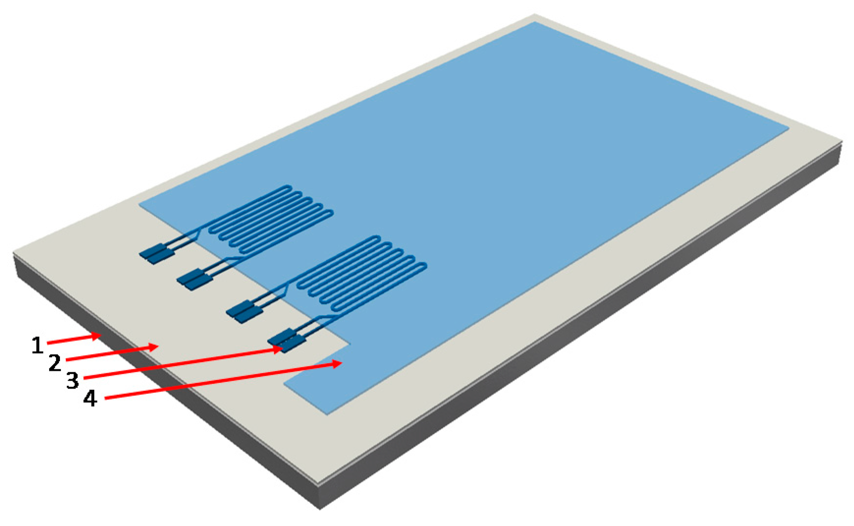
Figure 1 shows a schematic of a sample, where the substrate is sheet steel with an organic coating pre-applied for electric isolation (1, 2). On top of that, the sensor is realized (3). Optionally the sensor is then top-coated with another organic polymer layer utilizing spin-coating technology. This fabrication procedure was described in detail earlier ([
1,
5]). The first and second strain gauge samples are printed with the following screen-print pastes: silver, (Henkel PF 050), and carbon black, (Henkel PR 406B). For the reference strain gauge sensor, PVD was utilized to deposit gold layers. While the first two material systems are based on particles embedded in polymer matrixes that require thermal curing, also the evaporated gold layer needs an additional annealing step to form a reliably stable strain gauge.
3. Discussion
Characterization of the realized structures yielded that with silver and carbon black, sensor layer thicknesses of ~4 μm and ~10 μm were obtained, while the gold layer strain gauge has a thickness of 100 nm. These geometric parameters results in an initial resistance of 340.7 Ω for silver, 44,400 Ω for carbon black, and 150 Ω for gold and a relative change in the range of ‰ when compressive or tensile strain in the range of ‰ is applied.
All measurements discussed in the following paragraph are conducted in controlled environmental conditions in a climate chamber WKL 100 from Weiss Technik. The parameters were set to 25 °C for temperature and minimum humidity, which, according to the datasheet, corresponds to 25% RH at 25 °C.
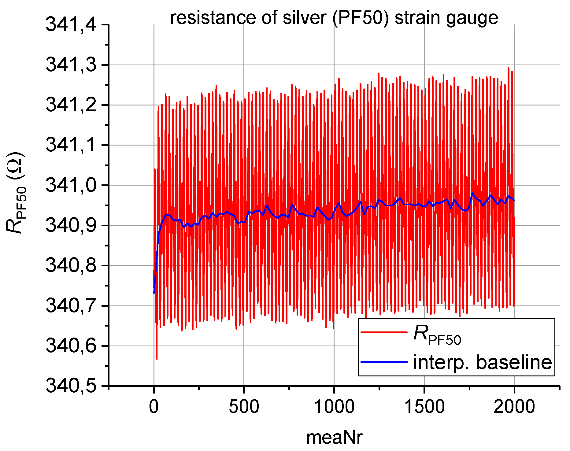
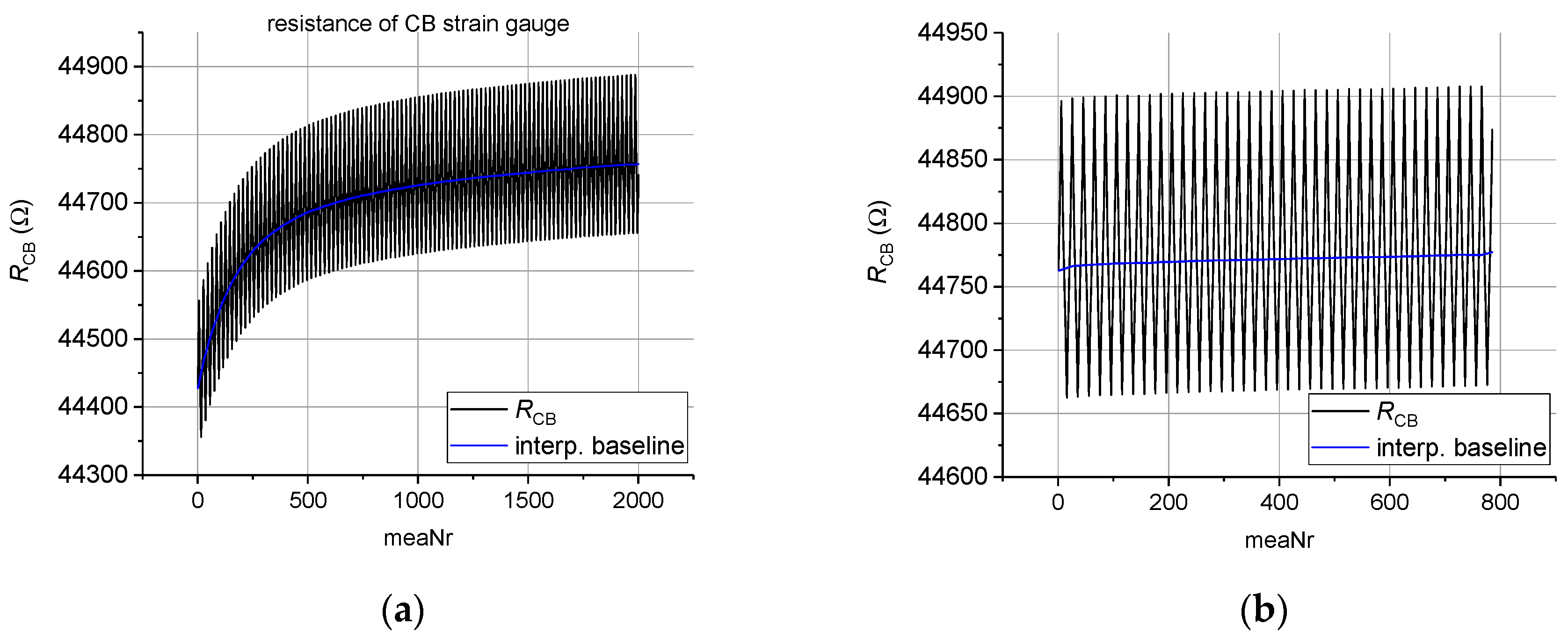
Figure 2 depicts one hundred measurement cycles of the silver-based strain gauge. One measurement cycle is defined as a movement of +5 mm to impinge compressive strain onto the strain gauge, followed by a movement of −10 mm to reach a −5 mm position and thus impinge tensile strain resulting in 20 measurement points per cycle. It is clearly observable that after the first 10 cycles the silver-based strain gauge is more or less stabilized. On the contrary, as can be seen in
Figure 3a showing the initial 100 cycles for the carbon black based strain gauge, it is evident that at least 90 are needed until the carbon black based sensor response can be presumed stable. To confirm this behaviour the same sample with carbon black was measured for a second time; again for 100 cycles.
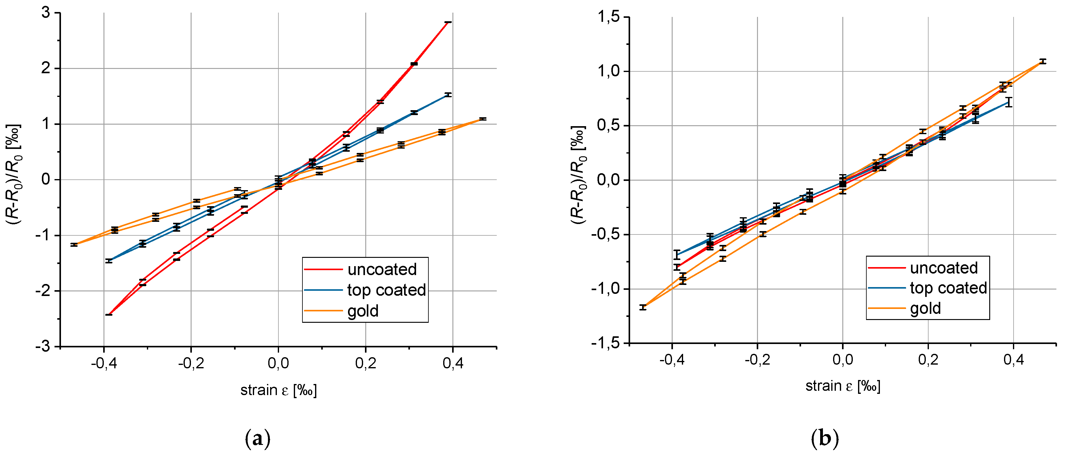
Figure 3b depicts the second run for carbon black; it shows that the sensor response has stabilized significantly and no set-in effect can be observed. Further, the influence of sensor fabrication on the nonlinearity of the gauge factor was investigated. It was demonstrated that the nonlinearity could be significantly reduced by introducing a stabilizing top coat. This behavior is shown in
Figure 4a,b. By introducing a top coat, the gauge factor of the silver strain gauge (compare
Figure 4b) does not change significantly only the slight nonlinearities at the turning points vanish. The carbon-based sensor (
Figure 4a) on the other hand becomes almost linear. In addition, its gauge factor is smaller after application of the top coat.
Finally, a hysteresis behavior that does not vanish after the initial baseline drift and remains after the application of a top coat is depicted in
Figure 4a and
Figure 4b. This suggests that some kind of rheological effect introduces this “lag” of the piezoresistive properties in case of the polymer-based inks. Furthermore
Figure 4a,b both depict an additional gauge factor measurement of pure gold. Since pure metallic strain gauges should respond linear and without hysteresis, the assumption that the hysteresis originates from the polymer coating can be made.
4. Conclusions
We showed that polymer based printed sensors need to be characterized thoroughly because they exhibit certain nonlinear effects. In addition, a mechanically stabilizing encapsulation is definitely improving the senor linearity, but with the slight drawback of reducing the sensor sensitivity. In conclusion, nonlinear effects can be attributed to the substrate coating since the comparison with a pure gold strain gauge showed the existence of a hysteresis as well.

 ,
, 