Proceeding Paper

The Effect of Temperature and Strain on Power Conversion Efficiency of PVDF-Based Thermal Energy Harvesters †

1
CEA, LETI, MINATEC Campus, F-38000 Grenoble, France
2
Université Grenoble Alpes, CNRS, Grenoble INP, G2ELAB, F-38000 Grenoble, France
*
Author to whom correspondence should be addressed.
Presented at the Eurosensors 2017 Conference, Paris, France, 3–6 September 2017.
Proceedings 2017, 1(4), 576; https://doi.org/10.3390/proceedings1040576
Published: 24 August 2017
(This article belongs to the Proceedings of Proceedings of Eurosensors 2017, Paris, France, 3–6 September 2017)

Abstract

:
There can be a significant discrepancy between predicted and measured power conversion efficiency when using piezoelectric polymers for thermal energy harvesting. The influence of temperature and strain on electrical parameters can impact overall performances. We report the temperature and strain dependence of PVDF dielectric constant and losses and their impact on power conversion efficiency of composite thermal SMA-PVDF energy harvesters.

1. Introduction

Electrical charges generated by energy harvesting need to be converted into useful voltage using high performance power conversion circuits. When the generation is piezoelectric, the voltage constant (g) is decisive, but for energy conversion the dielectric constant (ε) and losses (tanδ) are also crucial quantities, particularly when considering thermal energy harvesting. Thus, temperature and strain dependence of these quantities must be taken into account to ensure optimal performance.
Recent results showed that PVDF composite harvesters are able to harvest DC-energy from thermal fluctuations or small temperature changes when coupled with shape memory materials (SMA) [1]. A power conversion circuit is connected to the harvester by a switch (thermal). The switch (normally off) closes when the SMA transition temperature is reached (by heating or cooling). The open-circuit piezoelectric pick voltage is then discharged into the circuit. A pick voltage of 400 V for a temperature threshold at 80 °C was reported [1]. The circuit described in [1] comprises a voltage rectifier stage, an inductor, an output capacity and a free-wheeling diode. The aim of the circuit is to convert the high voltage generated by the PVDF into a useful voltage of 1.5 V. The theoretical conversion efficiency of the circuit can reach 90% at room temperature. However, real circuit performances usually collapse with temperature. In order to obtain the most efficient system with temperature and strain variations, the power conversion circuit has to be impedance matched to the SMA-PVDF composite material during the transition. Previous work [2] showed the impact of the temperature on the dielectric constant of PVDF. However, cumulative effects of temperature and strain are not reported.
In this paper, we will consider the PVDF element as a non-perfect capacitor. The change of the dielectric constant with temperature (from 30 °C to 60 °C) and strain (from 0% to 2.5%) is measured.

2. Experiments

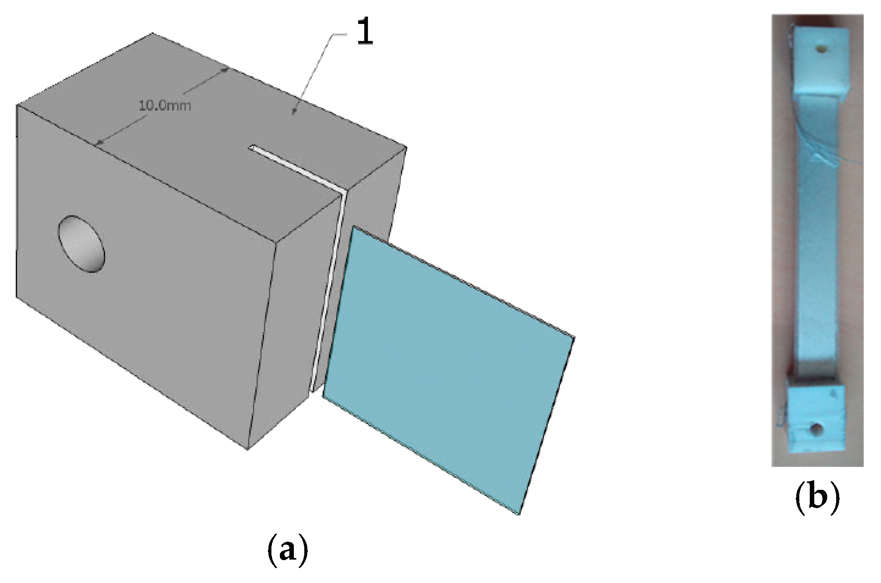
2.1. Sample Preparation

Taking into account the geometric specification to apply uniform strain to the sample [3], the capacitors are cut in the 110 µm-thick stretched metallized PVDF film from TE connectivity with a length to width ratio upper than 8. The top and bottom electrode are then etched at the edges in order to avoid electrical short-cuts. The non-metallized areas on both ends of the sample are then glued with cyanoacrylate glue into 3D-printed clamps and dried for 24 h as shown in Figure 1a. The clamps allow a firm fixation of the polymer samples during stretching. The “active” capacitor area between the two clamps has a length of 80 mm and a width of 10 mm. Contacts on electrodes are insured with flexible wires attached with silver lacquer and connected to the measurement circuit. Figure 1b shows a sample ready to use in clamps.

2.2. Measurements

In order to observe the cumulative impact of temperature and strain, an adjustable mechanical support is used to strain the capacitor sample and placed in a thermostatically controlled oven. The temperature is increased from 30 °C to 60 °C by steps of 10 °C. For each temperature steps, the strain is increased from 0% to 2.5% by steps of 0.5%.
The impedance of the capacitor is measured with a HIOKI impedance-meter from 1 kHz to 5 MHz. The dielectric constant of PVDF is extracted using a non-ideal capacitor equivalent circuit.
Nyquist diagrams of the dielectric constant are reported on Figure 2a,b. The impact of the temperature at constant strain (2.5%) is shown on the left, that of the strain at the constant temperature (60 °C) on the right.

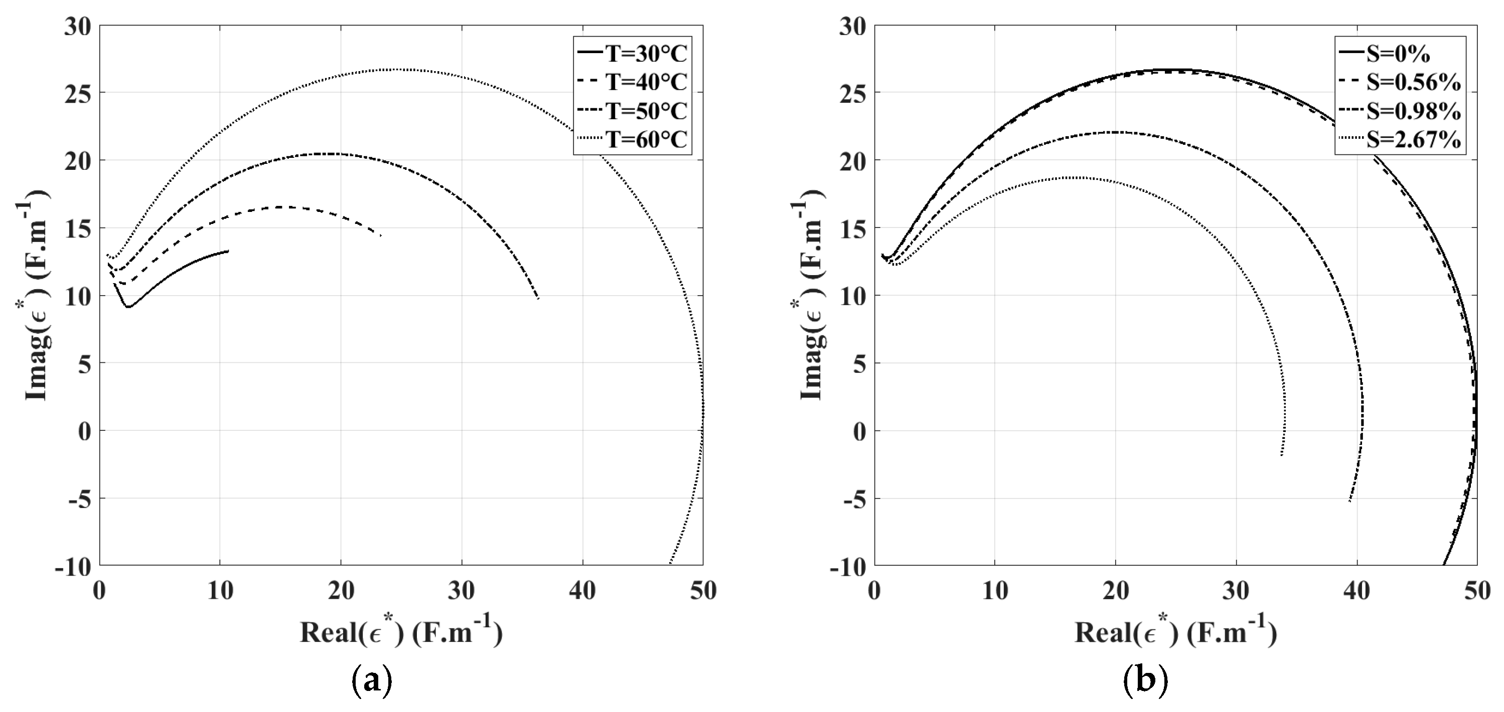
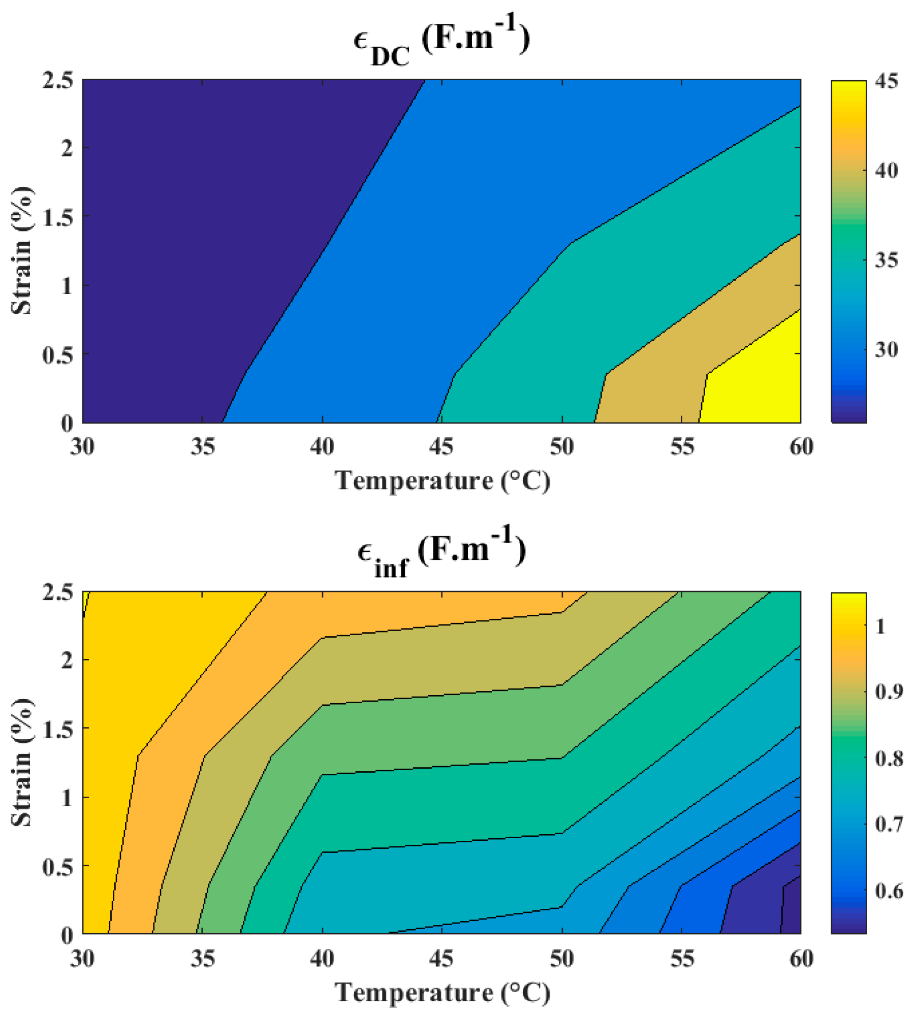
2.3. Results and Discution
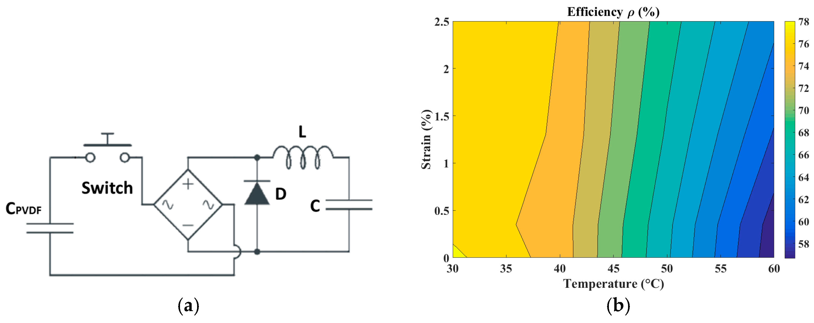
The frequency dependent dielectric constant is usually described by the Debye equation [4]:
ε * = ε i n f + ε D C ε i n f 1 + i ω τ ,
where εDC is the dielectric constant at low frequency, εinf is the dielectric constant at high frequency. ω represents the angular frequency and τ the relaxation time.
However, polymers rarely follow the Debye theory because of lower losses as compared to single relaxation processes in inorganic dielectrics. Cole [5] has proposed a modified equation by adding a corrective factor α calibrated from 0 to 1 as shown in Equation (2):
ε * = ε i n f + ε D C ε i n f 1 + ( i ω τ ) 1 α   ,
By introducing the real and the imaginary part of the dielectric constant, Equation (2) can by written as shown in Equation (3):
( I m a g ( ε * ) R e a l ( i α ) 2 I m a g ( i α ) ( ε D C ε i n f ) ) 2 + ( R e a l ( ε * ) ( ε D C + ε i n f ) 2 ) 2 = ( ε D C ε i n f 2 I m a g ( i α ) ) 2 ,
From this equation, the different parameters can be extracted by finding the position of the center of the circle and its radius. The extracted PVDF dielectric constants at low and high frequency as a function of the strain and the temperature as shown in Figure 3.
As seen on Figure 3, at constant strain, εDC increases and εinf decreases with increasing temperature, which increases the overall variation of ε*. Advantageously, with higher strain the temperature dependence weakens. The results also show that εDC is about 50 times larger than εinf and therefore dominates with PVDF. Additionally, as we consider slow temperature and strain variations, εDC is the preponderant quantities for application. In these conditions, extreme variation of εDC can reach +80% at 60 °C and 2.5% strain which is very significant compare to the usual fixed room temperature quantities. These variations must be taken into account in the power management circuit model.

3. Circuit Model

The power management circuit is shown in Figure 4a, comprising a switch that commutes when the PVDF capacitor is fully charged [1]. Component references are: (D) diode MURS120G3T, (L) inductor MSS1210-105KED Coilcraft (1 mH), and (C) capacitor VJ0805Y472KXCAC- Vishay (20 nF). The calculated circuit efficiency as a function of temperature and strain is reported on Figure 4b.
Usually, the output capacitor C is chosen to match the standard PVDF capacitance (room temperature, no strain) to meet this condition. In that case, the model predicts a maximum efficiency of 75% (with losses) when C = CPVDF. However, at 60 °C and 2.5% strain the measured efficiency was only 61%. This can be explained by the increase in PVDF capacitance in operation (25% at T = 60 °C and S = 2.5%) in agreement with the observed change of the dielectric constant (Figure 3). Finally, to restore the circuit efficiency in operation the output capacitance C must be decreased in proportion to be adapted to operation conditions. Thereby, the measured efficiency is 80%.

4. Conclusions

The discrepancy between predicted and measured power conversion efficiency when using coupled SMA-PVDF composite for thermal energy harvesting was explained. The influence of temperature and strain in operation significantly modifies the starting PVDF capacitance and impacts overall circuit performances. The change of the dielectric constant of PVDF as function of the temperature and applied strain is reported. The adjustment of the circuit output capacitance in proportion is necessary to ensure high power conversion efficiency.

Conflicts of Interest

The authors declare no conflict of interest.

References

  1. Gusarov, B.; Gimeno, L.; Gusarova, E.; Viala, B.; Boisseau, S.; Cugat, O. Flexible composite thermal energy harvester using piezoelectric PVDF polymer and shape memory alloy. In Proceedings of the 18th International Conference on Solid-State Sensors, Actuators and Microsystems (TRANSDUCERS), Anchorage, AK, USA, 21–25 June 2015. [Google Scholar]
  2. Vikram, S. Dielectric Properties of Pure Poly Vinylidene Fluoride (PVDF) thin films. In Proceedings of the IMECS 2010, Hong Kong, China, 17–19 March 2010. [Google Scholar]
  3. Gusarov, B.; Gusarova, E.; Viala, B.; Gimeno, L.; Cugat, O. PVDF piezoelectric voltage coefficient in situ measurements as a function of applied stress. J. Appl. Polym. Sci. 2016, 133, 1–6. [Google Scholar] [CrossRef]
  4. Debye, P. Polar Molecules; Chemical Catalog Co., Inc.: New York, NY, USA, 1929. [Google Scholar]
  5. Cole, K.S.; Cole, R.H. Dispersion and absorption in dielectrics 1. Alternating current characteristics. J. Chem. Phys. 1941, 9, 341–351. [Google Scholar] [CrossRef]
Figure 1. (a) Schematic drawing of the clamp for polymer film. Part 1 is 3D-printed in which the polymer film is glued; (b) Picture of a PVDF capacitor sample ready to use.
Proceedings 01 00576 g001
Figure 2. Nyquist diagrams of the PVDF dielectric constant, (a) with temperature change at constant strain (2.5%) and (b) with different applied strain at constant temperature (60 °C).
Proceedings 01 00576 g002
Figure 3. Evolution of PVDF dielectric constant at low and high frequency with applied strain and temperature.
Proceedings 01 00576 g003
Figure 4. (a) Power management circuit [1], and (b) efficiency as function of temperature and strain.
Proceedings 01 00576 g004
Publisher’s Note: MDPI stays neutral with regard to jurisdictional claims in published maps and institutional affiliations.

