Proceeding Paper

Intelligent Robot Guidance in Fixed External Camera Network for Navigation in Crowded and Narrow Passages †

1
Lab of Robotics and Dynamics, Graduate School of Engineering, Hokkaido University, Sapporo 060-0808, Japan
2
Lab of Robotics and Dynamics, Faculty of Engineering, Hokkaido University, Sapporo 060-0808, Japan
*
Author to whom correspondence should be addressed.
Presented at the 3rd International Electronic Conference on Sensors and Applications, 15–30 November 2016; Available online: https://sciforum.net/conference/ecsa-3.
Proceedings 2017, 1(2), 37; https://doi.org/10.3390/ecsa-3-D008
Published: 15 November 2016

Abstract

:
Autonomous indoor service robots use the same passages which are used by people for navigation to specific areas. These robots are equipped with visual sensors, laser or sonar based range estimation sensors to avoid collision with obstacles, people, and other moving robots. However, these sensors have a limited range and are often installed at a lower height (mostly near the robot base) which limits the detection of far-off obstacles. In addition, these sensors are positioned to see forward, and robot is often ’blind’ about objects (ex. people and robots) moving behind the robot which increases the chances of collision. In places like warehouses, the passages are often narrow which can cause deadlocks. We propose to use a network of external cameras fixed on the ceiling (ex. surveillance cameras) to guide the robots by informing about moving obstacles from behind and far-off regions. This enables the robot to have a ’birds-eye view’ of the navigation space which enables it to take decisions in real-time to avoid the obstacles efficiently. The camera sensor network is also able to notify the robots about moving obstacles around blind-turns. A mutex based resource sharing scheme in camera sensor network is proposed which allows multiple robots to intelligently share narrow passages through which only one of the robots/person can pass at a given time. Experimental results in simulation and real scenarios show that the proposed method is effective in robot navigation in crowded and narrow passages.

1. Introduction

To set the scene for this paper, consider the following examples explaining the two common problems faced by mobile service robots:
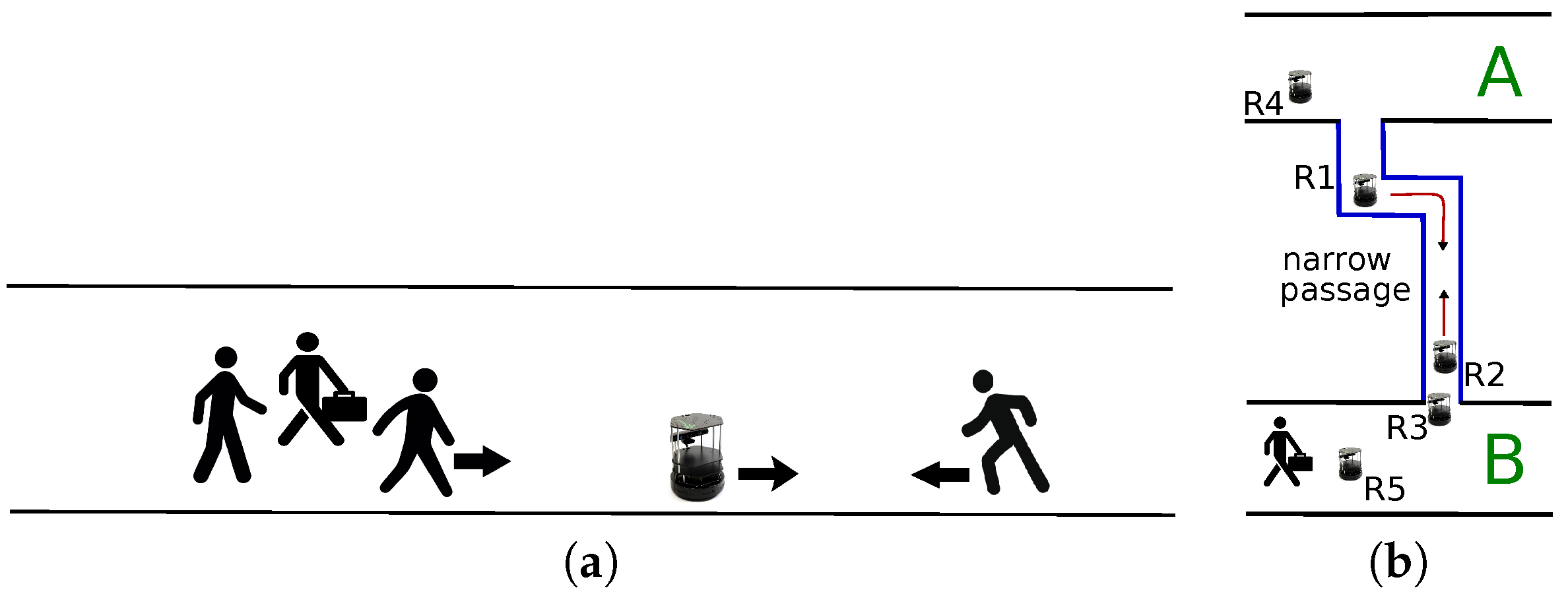
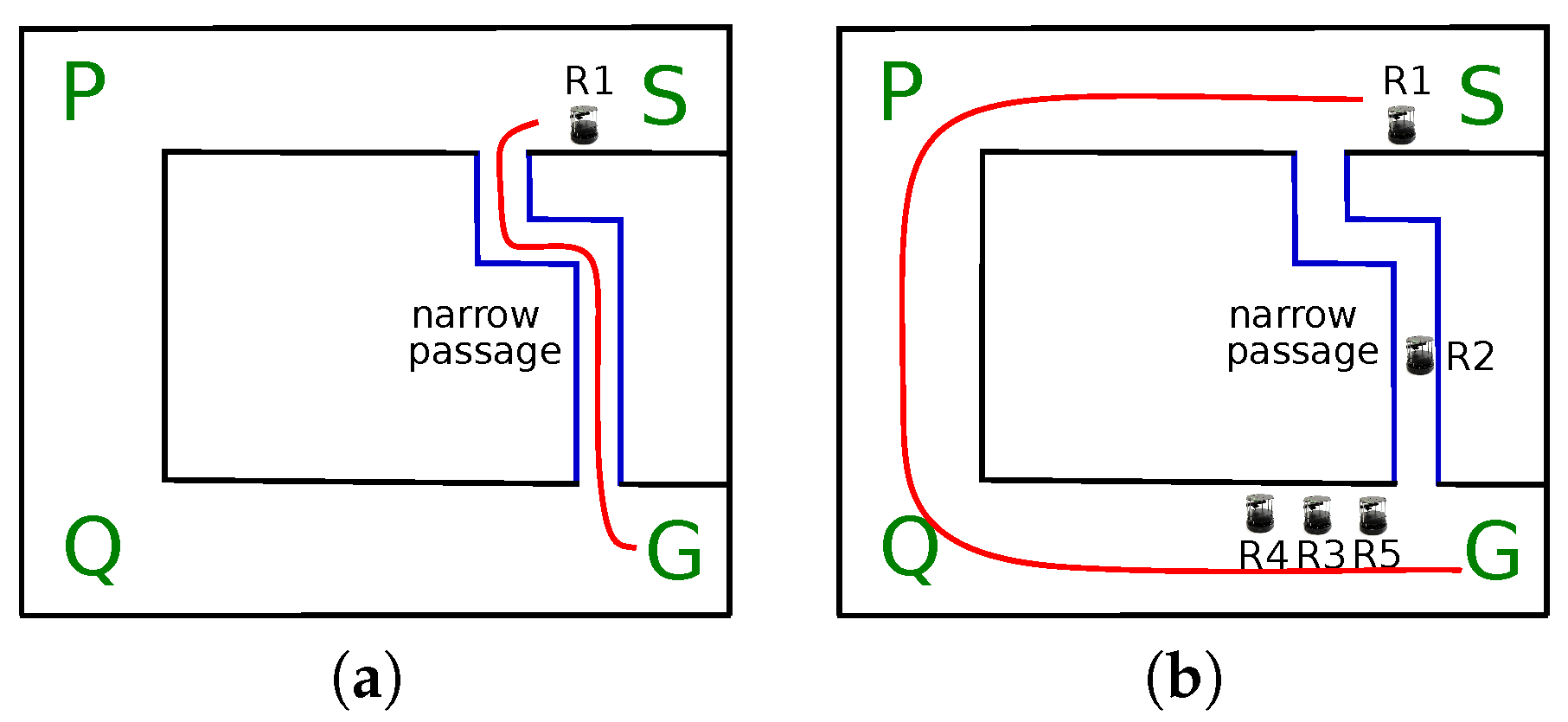
  • Example 1: Service robots often have sensors like cameras to perceive the external world and perform tasks like collision avoidance. Most of the times these sensors are ‘forward’ facing. As shown in Figure 1a, this causes the robot to be unaware of the movement of people or other robots in the back. Similarly, they are attached at low height due to which the robot cannot see far off obstacles, particularly in case of occlusion which is also shown in Figure 1a. The mobile robot must change its trajectory according to the movement of people approaching the robot from the back. Similarly, the robot could be in a better position to plan a trajectory if it could also get information about far off entities in the environment.
  • Example 2: To maximize area utilization, most of the passages of warehouses, libraries etc. are too narrow. While people are known to demonstrate flexibility to cross-over in such narrow passages, most of the mobile robots are rigid for such crossover to successfully occur in narrow passages. As shown in Figure 1b, robot R1 and R2 are in a deadlock condition and either has to retreat to make way for another robot. The problem is more complex if movement of multiple robots and people is also considered. In Figure 1b, it is possible for robots R3, R4, or R5 and some person to try to access the narrow passage. In the absence of a policy to resolve conflicts, the robots might be perpetually retreating which is inefficient. The policy must first avoid such conflicts by careful planning, and if the conflicts occur then they must be resolved intelligently by taking into account many important factors like the power availability of the robots and the priority of the task undertaken.
Regarding the state of the art, using external cameras with robots has been proposed earlier but with application to localization [1], automatic calibration [2], and pose estimation [3]. In the current work, we discuss the case of using external camera sensor network for sharing narrow paths, and providing visual information to robot about blind spots for trajectory planning and path planning.

1.1. Main Idea of This Paper

The main idea of the paper is that a network of external camera sensors can help the robots to resolve the aforementioned (and many other) problems. Regarding the first problem, an external camera can provide a ‘birds eye view’ of the world to the robots (Figure 2a) which can use this information to perceive movement of people in the back and carefully change its trajectory to make way for the people to avoid accidents. The birds eye view can also provide information about far off obstacles.
The same camera sensor network can also be used to design a shared resource allocator for multiple robots (Figure 2b). The shared resource in the context of the second problem is the narrow passage. We have designed a modified priority-queue based allocator for multiple robots which intelligently avoids conflict and allots the path to the most appropriate robot considering factors like the power availability of the robots and the priority of the task undertaken.

2. Graph Representation of Environment

In this section we describe the architecture of the system and define terms used in the rest of the paper. It is convenient to represent an environment comprising of cameras, processing boards, pathways, and direction of flow of people in the passages, into a node map, which is essentially a directional graph with nodes and links, which are defined as below.
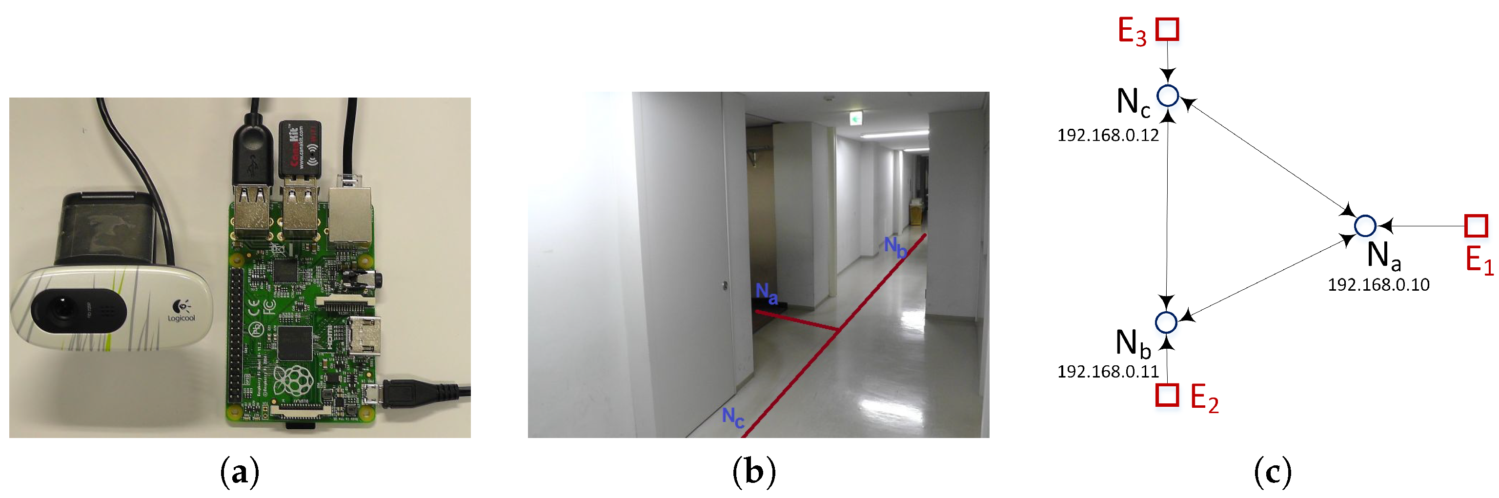
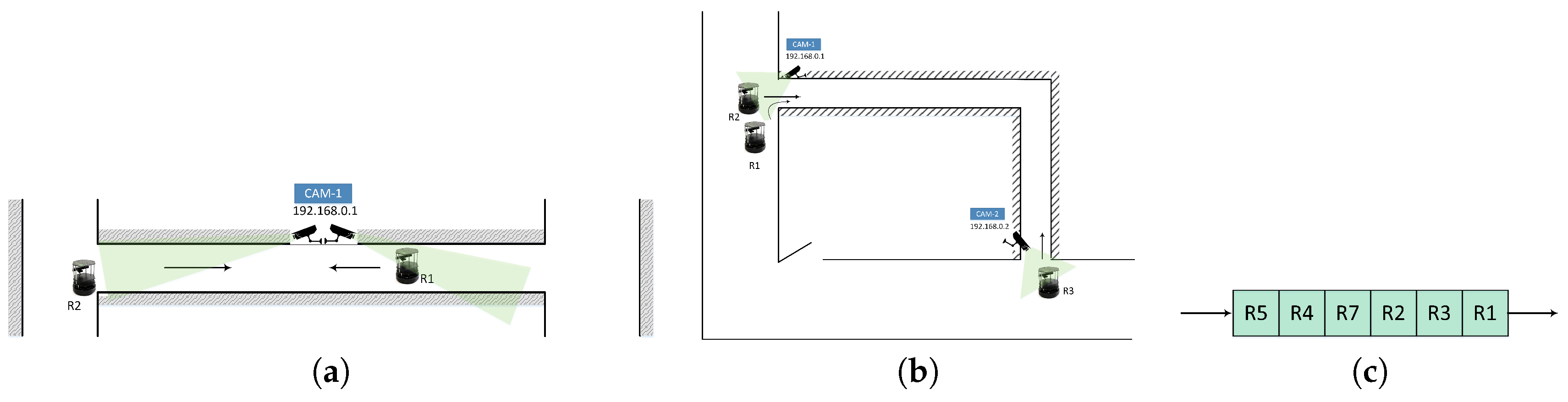
  • Node: A node comprises of a processing board with camera attached to it. Depending upon the processing capability of the board, multiple cameras could be attached to the same board.
  • Links: A link connects two nodes and represents the spatial path between two processing boards (or nodes). Links could be directional, representing not only the vector of traffic flow, but also the vector of source node and destination node in node communication.

3. Modified Priority Queue

The resource allocator maintains a database of the power required by the robots to do various tasks. Each task is given a unique ID ( T i ) and task priority ( T P ). Tasks related to security like surveillance and patrolling are given high priorities, whereas tasks related to cleaning, etc. are given lower priorities, as summarized in Table 1. A robot records its battery status before the task and when the task is finished. The power ( P i ) required to perform the i t h task is calculated as,
P i = P before i th task P after i th task .
P i for a task T i can be different for each run and an effective power ( P E ( i ) ) for the i t h task is calculated. Similarly, a robot can be instructed to perform a series of (‘m’) tasks, and a total effective power is calculated as,
P E ( x ) = 1 N i = 1 N P T ( x i ) ) . P t o t a l = i = 1 m P E i .
Robots which want to access the narrow passage sends a request to the node. Requests from multiple robots are maintained in a modified queue [4]. The queue is a ‘modified’ queue in the sense that it differs from the traditional ‘first-in first-out’ queue, but maintains a ‘score’ which determines which robot needs to be allotted to the resource.
Request from the robot comes in the form of a key-value pair of the robot-id ( R i ), and a corresponding vector ( Λ i ) which comprises of the task priority ( T p i ), and current power level ( P l i ). Hence, a request message is a dictionary key-value pair of { R i : Λ i } , where,
Λ i = { T p i , P l i } .
The allocator calculates a score from all robot requests ( { R i : Λ i } ). A score determines which robot needs to be given preference to have access to the narrow path. Robots which have high task priorities needs to be prioritized. Similarly, robots with low battery power may get stuck in the path thereby blocking it and must be prioritized too. Therefore, a score is calculated as,
Priority Score = 1 Power Left × Task Priority = W P · 1 P l n × W T · T p n
where, W P and W T are the weighing coefficients for the power preference, and the task-priority preference, respectively. The coefficients increase or decrease the effect of the power left and the task priorities on final priority score. For small robots with limited power and fast discharging, higher W P value, and in conditions where task priorities must definitely be obeyed, a higher W T value will affect the priority score, as desired.
Listing 1: An Example of Robot’s Request in JSON Format.
Proceedings 01 00037 i001
However, a robot may be in emergency condition where the battery power is just about to go off. Such ‘emergency’ situations needs to be handled separately as a service robot whose battery is completely discharged may stop in the middle of the passage, which may be an obstruction for other robots, or may even permanently block the way if the passage is narrow. Such a situation can be avoided by a service robot by requesting a quick access to the resource when the battery power level is below a certain threshold ( P T H ). Hence, in such ‘emergency’ cases, the robot request for access to the path is given the highest priority and hence the score is set to a maximum possible value. The priority score is calculated as,
Score , S = , if P l n P T H W P · 1 P l n × W T · T p n , otherwise
A score is calculated for all the request messages in the queue from { R i : Λ i } , and the messages are sorted according to the score in the queue. The message with the highest score is prioritized. Hence, unlike a traditional first-in first-out queue, requests can be processed from any position of the queue. If two requests have the same score, then, the earlier request is processed first, like in a normal queue. In case of multiple camera nodes at either ends of the passage, a common priority queue is maintained and updated by each node.

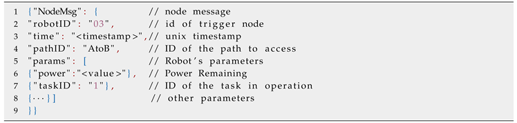
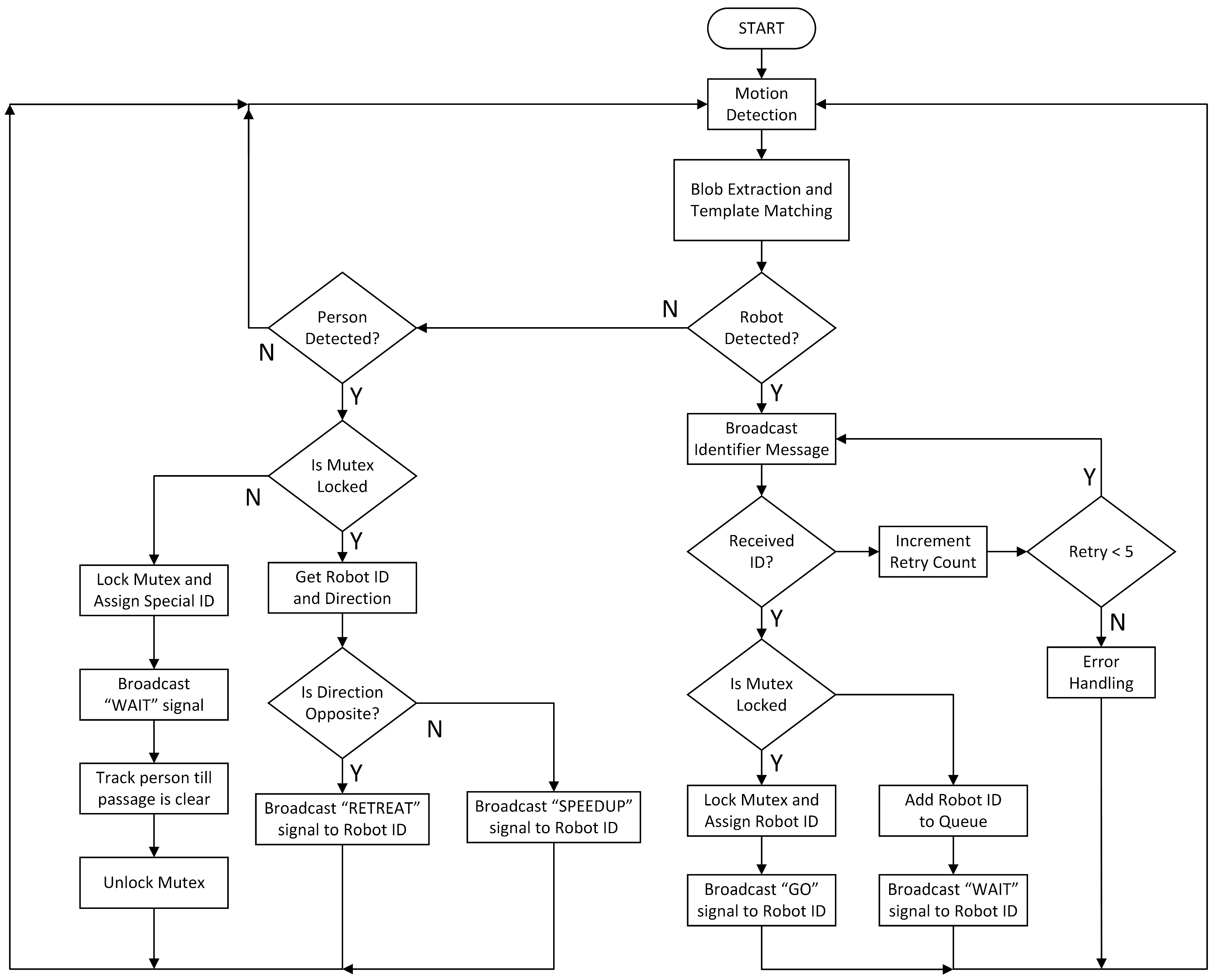
4. Path Allocation Process

Figure 3 shows the flowchart of the narrow path allocation. Each camera node has image processing modules to detect motion, extract blobs and match templates. If a robot is detected and there is a request from the robot, there is a handshake between the robot and the camera node. To avoid message lost scenarios, the node tries to receive the message several times. A sample request message is shown in Listing 1. The request is appended in the modified priority queue, a score is calculated, and the priority queue is sorted.
Resource sharing is done via mutex mechanism which provides mutual exclusion, i.e., only one robot can have the key (mutex) and proceed on the narrow path. As long as the mutex is locked, other robots needs to wait. Other approaches like semaphores can also be used. A mutex is maintained and if the score is high a check is performed if the mutex is locked or not. If not, the robot with high score is assigned the key and access to the path and the mutex is locked until the robot has traversed the path. If the mutex is locked, the other robots wait until it is available.
If a person is detected and the path is not being accessed the mutex is immediately locked. If the mutex was locked, a check is performed if the direction of person’s movement is same or opposite to that of the robot accessing the path. If the direction is same, then the robot is notified and instructed to speedup. If the directions are opposite, then the robot is notified and instructed to stop or retreat depending on the width of the path.

5. Experimental Results

We implemented the proposed system using three nodes in a ‘T’ shaped environment shown in Figure 4b. The node map of the test environment is shown in Figure 4c. The configuration of each node is as shown in Figure 4a. In our implementation, a node comprised of a Raspberry Pi board which features a 700 MHz Low Power ARM11 processor with 512MB of SDRAM, and a webcam attached to it. It has a 10/100 BaseT Ethernet socket but no wifi capabilities, so we used an external wifi adapter. All the nodes were assigned a unique IP address (as shown in Figure 4c), and could communicate with each other and the robot in vicinity. The robots used were: (a) Kobuki Turtlebot [5]; and (b) Pioneer P3DX [6]. We performed tests for both person detection and robot detection being the trigger event. Each node ran three modules: (1) Face detection (to identify person); (2) Robot detection; and (3) Allocator module with the modified priority queue.
Figure 5a shows the person around node N a . Figure 5b,c shows the background difference image [7] and threshold image, respectively. Similarly, Figure 6a shows the appearance of a robot in the FOV of node N b . Figure 6b,c shows the background difference and threshold images, respectively. As soon as the person is detected, the mutex was locked and the robot was made to wait until the path was free, after which, the robot resumed motion on the path.
Figure 7a shows the case of occlusion of the field of view by a person from robot’s perspective. However, image from the external camera viewpoint shown in Figure 7b clearly shows objects ahead which were extracted by the robot. Similarly, Figure 7c shows a person detected behind the robot and notified to the robot. Figure 7d shows that the robot shifted to the right to consider motion of the person from behind to avoid being a hindrance and prevent any accident.
Figure 8 show the simulation results with the proposed resource allocator. In Figure 8a, robot R1 takes the shortest path from start location ’S’ to the goal ’G’. However, in case of Figure 8b, with path locked by R2 and R3, R4, R5 in queue, R1 plans a long route SPQG which is more efficient than waiting long.

6. Conclusions

Our results show that robots can benefit from external sensor networks in which they operate. Vision is a powerful information and most of the public places like hospitals, universities, and airports already have a large network of surveillance cameras installed. Therefore, there is no need to specially install a new infrastructure and there are cost benefits. The main contribution of the proposed idea is that the robots operating in the sensor network are no longer limited to the attached sensor specifications. Rather, robots can access a rich content of information from the sensor network for better navigation. The proposed idea is not limited to vision sensors, and robots can access a wide range of relevant information from different types of sensors to perform their tasks more efficiently.

Author Contributions

Abhijeet Ravankar and Ankit Ravankar conceived the idea, designed, and performed the experiments; Yukinori Kobayashi and Takanori Emaru made valuable suggestions to analyse the data, improve the manuscript, and provided the necessary tools. The manuscript was written by Abhijeet Ravankar.

Acknowledgments

This work is supported by Ministry of Education, Culture, Sports, Science and Technology, Japan.

Conflicts of Interest

The authors declare no conflict of interest.

References

  1. Pizarro, D.; Marron, M.; Peon, D.; Mazo, M.; Garcia, J.C.; Sotelo, M.A.; Santiso, E. Robot and obstacles localization and tracking with an external camera ring. In Proceedings of the IEEE International Conference on Robotics and Automation (ICRA 2008), Pasadena, CA, USA, 19–23 May 2008; pp. 516–521. [Google Scholar]
  2. Ji, Y.; Yamashita, A.; Asama, H. Automatic calibration and trajectory reconstruction of mobile robot in camera sensor network. In Proceedings of the IEEE International Conference on Automation Science and Engineering (CASE), Gothenburg, Sweden, 24–28 August 2015; pp. 206–211. [Google Scholar]
  3. Pizarro, D.; Santiso, E.; Mazo, M.; Marron, M. Pose and Sparse Structure of a Mobile Robot using an External Camera. In Proceedings of the IEEE International Symposium on Intelligent Signal Processing (WISP 2007), Alcala de Henares, Spain, 3–5 October 2007; pp. 1–6. [Google Scholar]
  4. Ravankar, A.; Ravankar, A.A.; Kobayashi, Y.; Jixin, L.; Emaru, T.; Hoshino, Y. An intelligent docking station manager for multiple mobile service robots. In Proceedings of the 15th International Conference on Control, Automation and Systems (ICCAS), Busan, Korea, 13–16 October 2015; pp. 72–78. [Google Scholar]
  5. TurtleBot 2. TurtleBot 2 Robot. Available online: http://turtlebot.com/ (accessed on 20 April 2017).
  6. Pioneer P3-DX. Pioneer P3-DX Robot. Available online: http://www.mobilerobots.com/ (accessed on 20 April 2017).
  7. Ravankar, A.; Kobayashi, Y.; Ravankar, A.A.; Emaru, T. A Connected Component Labeling Algorithm for Sparse Lidar Data Segmentation. In Proceedings of the 6th International Conference on Automation, Robotics and Applications (ICARA 2015), Queenstown, New Zealand, 17–19 February 2015. [Google Scholar]
Figure 1. Two common problems of service mobile robots. (a) Robots are mainly unaware of the moving entities like people/robots behind or far which can cause accidents; (b) Problem of deadlock in narrow passages. Either robot R1 or R2 has to retreat to make way for the other robot.
Proceedings 01 00037 g001
Figure 2. Robots in camera sensor network. (a) Cameras providing birds eye view of the environment to the robots; (b) Path allocation by allocator considering factors like task priority and available power; (c) Requests from robots to access path are saved in a queue from which a score is calculated.
Proceedings 01 00037 g002
Figure 3. Flowchart of path allocation to robots.
Proceedings 01 00037 g003
Figure 4. Experiment setup. (a) Node comprising of a Raspberry Pi board with camera; (b) ‘T’ shaped experimental passage; (c) Graph representation.
Proceedings 01 00037 g004
Figure 5. Person detection at node. (a) RGB image; (b) Background difference image; (c) Threhold image; (d) 1 person detected.
Proceedings 01 00037 g005
Figure 6. Robot detection at node. (a) RGB image; (b) Background difference image; (c) Threhold image; (d) 1 robot detected.
Proceedings 01 00037 g006
Figure 7. (a) Robot’s camera view in which person occludes the robot in front; (b) External camera view which enables to see far off objects like robot; (c) Robot moving straight; (d) Robot turning right to make way for person approaching from back.
Proceedings 01 00037 g007
Figure 8. Path planning in sensor network from start ’S’ to goal ’G’ location. (a) Robot R1 takes the shortest route via narrow passage when free; (b) With path locked by R2 and R3, R4, R5 in queue, R1 plans a long route SPQG which is more efficient than waiting long.
Proceedings 01 00037 g008
Table 1. Database of Tasks, Task ID, Task Priority, and Required Power.
TaskTask ID ( T i )Task Priority ( T p )Required Power( P i )
Surveillance T 1 10 P 1
Delivery T 2 3 P 2
Patrolling T 3 8 P 3
Cleaning T 4 9 P 4
Others T 5 7 P 5
Publisher’s Note: MDPI stays neutral with regard to jurisdictional claims in published maps and institutional affiliations.

