Article

Arithmetic Harris Hawks-Based Effective Battery Charging from Variable Sources and Energy Recovery Through Regenerative Braking in Electric Vehicles, Implying Fractional Order PID Controller

by
Dola Sinha
1,
Saibal Majumder
2,*,
Chandan Bandyopadhyay
2,3 and
Haresh Kumar Sharma
4
1
Department of Electrical Engineering, Dr. B. C. Roy Engineering College, Durgapur 713206, India
2
Department of Computer Science and Engineering (Data Science), Dr. B. C. Roy Engineering College, Durgapur 713206, India
3
Department of Computer Science and Engineering, University of Bremen, 28359 Bremen, Germany
4
Department of Operations Management and Decision Sciences, Birla Institute of Management Technology, Greater Noida 201306, India
*
Author to whom correspondence should be addressed.
Fractal Fract. 2025, 9(8), 525; https://doi.org/10.3390/fractalfract9080525
Submission received: 16 July 2025 / Revised: 7 August 2025 / Accepted: 7 August 2025 / Published: 13 August 2025

Abstract

A significant application of the proportional–integral (PI) controller in the automotive sector is in electric motors, particularly brushless direct current (BLDC) motors utilized in electric vehicles (EVs). This paper presents a high-performance boost converter regulated by a fractional-order proportional–integral (FoPI) controller to ensure stable output voltage and power delivery to effectively charge the battery under fluctuating input conditions. The FoPI controller parameters, including gains and fractional order, are optimized using an Arithmetic Harris Hawks Optimization (AHHO) algorithm with an integral absolute error (IAE) as the objective function. The primary objective is to enhance the system’s robustness against input voltage fluctuation while charging from renewable sources. Conversely, regenerative braking is crucial for energy recovery during vehicle operation. This study implements a fractional-order PI controller (FOPI) for the smooth and exact regulation of speed and energy recuperation during regenerative braking. The proposed scheme underwent extensive simulations in the Simulink environment using the FOMCON toolbox version 2023b. The results were validated with the traditional Ziegler–Nichols method. The simulation findings demonstrate smooth and precise speed control and effective energy recovery during regenerative braking and a constant voltage output of 375 V, with fewer ripples and rapid transient responses during charging of batteries from variable input supply.

1. Introduction

Technological progress has allowed for the development of electric vehicles (EVs) to address social needs. As more people switch to electric vehicles, combustion engines will become less common, which means less pollution. Hence, battery charging has become a very pressing issue that is now garnering a lot of focus. Concerns about electric vehicles primarily revolve around the availability of charging facilities. Regularly updating the battery’s health status is crucial for safety reasons, and there is space for improvement in speed control.
An essential component of any electric vehicle’s navigation system is the electric motor. Electric vehicles can employ a variety of electrical motors. Using magnet-less motors instead of magnet motors is one approach to reducing electric vehicle (EV) subsystem costs according to [1]. Electric car motors are either BLDCs, which are high-efficiency brushless direct current motors, or permanent magnet synchronous machines (PMSM), which are permanent magnet synchronous motors. They can be demagnetized and are susceptible to rare earth minerals, which are costly [2]. Future induction and switch reluctance motors reduce costs by avoiding the usage of expensive magnets. Torque ripple, noise in switch reluctance motors (SRMs), and losses in induction motors (IMs) are some of the problematic concerns in electric vehicle (EV) applications [3].
Research has shown that there are several subtypes of electric vehicles, such as plug-in hybrids, pure electrics, hybrids, and fuel cell electric vehicles (FCEVs) [4,5,6]. Speed regulation is a significant attribute of electric vehicles. Electric vehicles are generally driven by electric motors, necessitating a controller to manage their velocity. The controller modulates the power provided to the motor, hence regulating the vehicle’s speed [7,8,9]. The controller acquires input from multiple sensors, such as the accelerator and braking pedals. The controller regulates the vehicle’s speed by modulating the power provided to the motor. During deceleration, an electric vehicle can modify the operational mode of its electric motor. The kinetic energy of the vehicle is then converted and stored in the battery by switching the electric motor to generator mode. Studies indicate that roughly 30–50% of an electric vehicle’s total energy in urban traffic is expended on friction braking, while 25–40% of the braking energy can be recaptured by regenerative braking. Furthermore, the motor’s quick response can more precisely monitor the appropriate slip rate of the wheels. Research indicates that, in comparison to forward breaking (FB), the average deceleration of regenerative braking (RB) is augmented by 10.9%, while the braking distance is reduced by 5% [10,11,12]. Consequently, RB is a crucial method for enhancing energy efficiency, increasing driving range, and improving braking performance of electric vehicles, garnering significant interest from both academics and industry [13,14]. The essential factor for attaining the previously described benefits is a real-time control technique that can synchronize RB and FB torque. Presently, numerous studies on the design of RB controllers exist, mostly concentrating on torque-coordinated control under both standard and emergency braking conditions. In typical braking scenarios, the regeneration control strategy is categorized into rule-based and optimization-based approaches, as outlined in Ref. [15]. The advantages and disadvantages of each method are evaluated, and the energy-recovery efficiency (ERE) is subsequently examined. The design methodology for RB controllers in emergency braking, encompassing proportional–integral–derivative control, sliding-mode control (SMC), model predictive control (MPC), and intelligent control, is detailed in Ref. [16]. Research [17] reviews the state-of-the-art technology and current advancements in anti-lock braking systems (ABSs) integrated with electric motors for pure electric vehicles (PEVs). Particular emphasis is placed on the implementation of slip estimators, the formalization of torque requirements, and control strategies for anti-lock braking systems (ABSs). The aforementioned study reviews mostly examine the influence of RB on partial vehicle performance. The advancement of regenerative braking systems (RBS) has imposed heightened demands on RB control, particularly regarding energy recovery, braking stability, and driving comfort [18]. Nevertheless, few research studies have systematically evaluated the overall efficacy of regenerative braking control systems, necessitating more exploration. Improving specific features, including decreasing speed errors, smoothly reaching the maximum speed, and enhancing energy recovery from regenerative braking, has been the primary focus of electric car motor speed control research.
Solar, wind, and hydroelectric power are examples of renewable energy sources that provide an eco-friendly and long-term solution. Additionally, to assist in the reduction in emissions of greenhouse gases and the mitigation of climate change, these sources are both plentiful and infinite. But the main problem of these renewable sources is their fluctuating nature, as their output depends on environmental parameters. For the steady operation of any application, constant voltage and power are necessary. So, to achieve this objective, different controlling techniques are developed with modern power electronic converters. Buck, boost, buck–boost are the basic voltage controlling converters. Here, we have used multi-input DC–DC boost converters. Different topologies of DC–DC boost converters are implemented by the researchers with respect to their operating conditions. For closed-loop control of traditional DC–DC boost converters, Saleem et al. [19] provide a fractional-order PID controller. For solar photovoltaic maximum power point tracking (PV MPPT) control using a buck–boost converter, Saleem et al. [20] have also presented an FoPID controller. Variations in irradiation have been taken into consideration for input voltage fluctuations. The output voltage was tracked by Saleem et al. [21] using a FoPID controller for DC–DC buck converters; the controller is utilized to eliminate steady-state errors and reduce oscillations. A single-input fuzzy-logic pre-compensator stage is added to the FoPI controller to improve the response’s error convergence rate.

2. Methodology

2.1. Architecture of Proposed Scheme of Battery Charging and Regenerative Braking Applied in EV

Figure 1 depicts the block diagram of the proposed scheme of effective battery charging and regenerative braking applied in EVs. Here, M stands for Motoring mode and G stands for generator mode. Initially, the scheme is proposed as the input power sourced from renewable sources, which is fed to the interleaved boost chopper to enhance its reliability and to obtain the desired amount of power at rated voltages. The interleaved boost chopper is controlled by an FoPI controller tuned with the Arithmetic Harris Hawks Optimization (AHHO) algorithm.
Regenerative braking is a technique of reclaiming energy that is converted or lost as heat during the application of brakes to decelerate a vehicle. During this mode, the motor’s operation changes from motoring mode to generating mode, and it feeds power to the source [22]. In the block diagram, it is shown that the bi-directional synchronous boost chopper is connected between a battery and 3-phase voltage source inverter. Power is fed to the 3-phase stator through this inverter.
During normal running conditions, a hall sensor provides information on the rotor’s position, and the inverter operates accordingly. During regenerative braking, when reverse power flows from the motor to the battery, the hall sensor also indicates the braking status to the inverter; using the FoPID controller, the switches of the synchronous boost chopper are controlled, and power is fed back to the battery. This FoPID controller is also tuned using the AHHO algorithm.
The FoPI controller is used for constant voltage and power output: The integral component in an FoPI controller can function at non-integer orders because fractional calculus is introduced into the classic PI controller. An extra parameter λ , which represents the ordering of the integral term, defines the FoPI controller. Interleaved DC–DC boost converters with variable inputs are examples of complicated and changeable environments, where the addition of an extra degree of freedom, denoted as λ , allows for increased flexibility and control over the system’s dynamics. The components K p and K i stand for the proportional and integral gains, respectively, while λ denotes the fractional order of integration. As time goes on, the response to mistakes becomes more accurate and polished because this representation makes the core action more flexible.
The precise regulation of a DC–DC boost converter with variable input is essential for maintaining the desired output voltage and current with minimal fluctuations and rapid adaptation to changes in the input voltage or load. This complex system is designed to handle these variations with ease. The incorporation of fractional-order terms into the FoPI controller makes it more complicated and diverse in its dynamic response, making it better at handling variations in system parameters than traditional PI controllers. Incorporating additional tuning parameters ( λ ) allows for accurate adjustment of the FoPI controller, leading to faster response times and reduced overshoot in response to input fluctuations. Thanks to its adaptability, the FoPI controller is ideal for adaptive control strategies, which enable the real-time adjustment of controller parameters to suit changing input conditions. This precise control over the dynamic response of the controller helps minimize fluctuations in output voltage and current, which is crucial for fast-charging the battery. To enhance the efficacy of the PI controller across a broader spectrum of variations, it is essential to modify the controller’s gains. The controller’s gains, i.e., proportional gain ( K p ) and integral gain ( K i ), are tuned using the Ziegler–Nichols (Z–N) method. This method involves finding the ultimate gain Ku and ultimate time period Tu through a closed-loop test. For the PI controller, the proportional gain ( K p ) is represented as follows:
K p = 0.45 K u .
Integral time T i is represented as follows:
T i = T u 1.2 .
Integral gain K i is represented as follows:
K i = K p T i = 0.45 K u T u 1.2 = 0.54 K u T u .
It is possible to tailor FoPI controllers to specific applications by adjusting the phase margin and crossover frequency. Additionally, they have a higher threshold for parameter-level and system-level changes. A few of the numerous advantages of FoPI controllers are enhanced robustness, better system control performance, and dynamical system control. One way to represent the transfer function of an FoPID controller is shown in Equation (4).
C s = K p + K i s λ + K d S μ
For FoPI controllers, the last term K d S μ will be omitted.
Hall Effect Sensors: Hall effect sensors are utilized in various parts of electric vehicles (EVs) to assess and regulate a vehicle’s performance. In this paper, Hall effect sensors are utilized for precise identification of the amateur position of BLDC motors during supply from a 3-phase inverter, determining the rotational speed of wheels and battery charging during regenerative braking. This enables the vehicle to regulate its torque output, hence enhancing stability and traction.
In order for the 3-phase voltage source inverter (VSI) to work, the positioning of the rotor is crucial. Hall sensors are used in sensor-based control to transmit rotor position data; their outputs have a 50% duty cycle and a 120° phase difference. The rotor’s speed determines the frequency of the sensor’s output. To turn the motor on and off, Hall effect sensors detect where the rotor is. For the BLDC motor to operate correctly, it must know the rotor’s positional data. In the past, there have been various approaches for determining the position of the rotor and for generating the necessary gating pulses for the VSI.
During deceleration, regenerative braking uses Hall effect sensors to collect energy, which is then stored in the battery. As a result, the vehicle’s efficiency and range are improved. Because of their longevity, dependability, and exceptional precision, Hall effect sensors are the preferred speed detection device for electric vehicles. They work at high rates without touching each other.
BLDC Motor in EVs: The choice of an electric motor is essential in determining the performance, efficiency, and user experience of electric vehicle (EV) propulsion. The BLDC motor is a widely utilized electric motor, recognized as an optimal choice due to its alignment with specific performance standards and efficiency. BLDC motors offer high power densities and efficient torque production across an extensive speed range, ensuring the requisite acceleration, velocity, and responsiveness for modern electric cars:
  • High Efficiency: BLDC motors exhibit exceptional efficiency across various operational conditions, ensuring optimal energy utilization and minimizing losses.
  • Power Density: The design of BLDC motors enables compact structures and lightweight construction, leading to an enhanced power-to-weight ratio.
  • Prolonged Lifespan: The absence of brushes in BLDC motors reduces mechanical wear, leading to extended operational lifespans and fewer maintenance requirements.
  • Regenerative Braking: BLDC motors facilitate regenerative braking, converting kinetic energy into electrical energy during deceleration, hence enhancing energy recovery.

2.2. Multi-Input Interleaved Boost Chopper for Fast and Effective Charging of Battery Source of EVs

A multi-input boost converter can accept different types of input sources, like solar cells, fuel cells, and other DC power sources. The inductors for a multi-input DC–DC converter are charged by a switching mechanism that plugs and unplugs numerous input sources one at a time or simultaneously. Three input power sources, Source 1, Source 2, and Source 3, are coupled as H-bridge cells, using L inductors, Metal-Oxide-Semiconductor Field-Effect Transistors (MOSFET), and diodes to charge the battery as shown in Figure 2. This battery is the main power source of EVs. This scheme can be directly connected to the main power supply line to feed power to the BLDC motor. This is because any fluctuation of the input sources can be overcome by the FoPI controller. But as the weight of the solar panels is heavy, this will enhance the dead weight of the EV; thus, we recommend storing energy in the battery. This mechanism is proposed for delivering exact and stable desired charging voltages and currents to charge a battery. Once the exact rated voltage is provided to the battery for charging, the battery will charge quickly. For DC charging stations, the battery can be quickly charged.
In the proposed scheme, the duty cycle of the semiconductor switch is the function of input voltage sources, and it is adjusted automatically according to the source voltages. Initially, it will check the input voltage available for any instant, and as the desired output voltage is fixed for the battery, it will set a value for the duty ratio using Equation (22).
V o = V s 1 D .
The voltage mismatch error between the initial output voltage of the boost chopper and the desired voltage is compared with repetitive waveforms, and using PI or FoPI controllers, accurate pulse width modulation (PWM) pulses are generated to operate semiconductor switches. The parameter gains of the FoPI controller are optimized using the Arithmetic Harris Hawks Optimization (AHHO) algorithm. For obtaining exact rated output voltages despite the fluctuating nature of input voltages, exact parameter gains are needed to obtain proper benefits from the interleaved boost choppers.

2.3. Chopper-Controlled BLDC Applied in EV

In the present scheme, we have used synchronous boost choppers to feed power from the battery to the 3-phase inverter. The inverter cannot change the voltage magnitude; it will only send power to the three phases of the BLDC motor. The voltage magnitude that is fed to the motor will be controlled by this synchronous boost chopper. The block diagram of energy recovered through regenerative braking is shown in Figure 3.
In the synchronous chopper, the diode of the converter is replaced by a MOSFET so that it can reduce power dissipation, reduce heat generation, and enhance efficiency. During the forward motoring mode, the motor consumes power from the battery. The induced armature emf E a   is less than the terminal voltage V t :
E a =   V t I a R a ,
where   I a is the armature’s current, and R a is the armature’s resistance:
V t =   E a + I a R a .
V t = K φ ω + I a R a ,
Here, E a = K φ ω , K is the motor constant, φ = field or stator excitation, and ω is the armature or rotor speed in rad/s.
The terminal voltage V t of the motor is the output voltage of the DC–DC converter (chopper). This implies
V t = V o .
Equation (8) can be written as
V o = K φ ω + I a R a .
V s = K φ ω + I a R a   for buck chopper .
V s 1 D = K φ ω + I a R a   for boost chopper .
where V s is the input voltage of the chopper and output voltage of the battery, and D is the duty ratio of the main switch.
ω = D V s I a R a K φ   for buck chopper .
ω = V s 1 D I a R a K φ   for boost chopper .
By controlling the duty ratio D , the desired speed of the motor can be achieved. When sudden braking or deceleration occurs, the motor starts operating in the generating mode. In the regenerative braking mode, the motor behaves like a generator. Before this, in the motoring mode, the terminal voltage across the motor is V t >   E a . The armature’s current flows in the reverse direction. In this mode, the terminal voltage of the motor becomes
V t = E a I a R a .
K φ ω = V o + I a R a .
The produced electromagnetic torque is
T e I a
The output power P o   from the chopper is
P o = V o I 0 = V o I a
The output current of chopper I o is the same armature current that was generated at the armature. During this regenerative braking mode, the voltage fed to the source (i.e., in batteries, it is the charging voltage) is represented as
V o = 1 D V s
K φ ω = 1 D V s + I a R a .
ω = 1 D V s + I a R a K φ .
The minimum speed during regenerative braking when D   = 1 is
ω m i n = I a R a K φ
The maximum speed during regenerative braking when D   = 0 is
ω m a x = V s + I a R a K φ
Control of the duty ratio speed and energy recovery can be achieved. In this paper, the duty cycle is controlled using PI and FoPI controllers.

3. Arithmetic Harris Hawks Optimization for Tuning of PI and FoPI

In recent years, metaheuristic algorithms have gained significant attention for solving complex and nonlinear optimization problems where traditional mathematical programming techniques may fail to perform efficiently. Among these algorithms, nature-inspired metaheuristics have shown remarkable success in providing near-optimal solutions within reasonable computational times. One such recent algorithm is the Harris Hawks Optimization (HHO) algorithm introduced by Heidari et al. [23], which mimics the cooperative behaviour and surprise pounce strategy of Harris Hawks during hunting. HHO combines exploration and exploitation phases dynamically, guided by the prey’s escaping energy, allowing it to balance diversification and intensification effectively.
However, despite its promising performance, the original HHO suffers from issues such as slow convergence speeds and a tendency to become trapped in local optima, especially when tackling high-dimensional or complex objective functions. To address these limitations, several improved variants have been proposed. One such enhanced version is the Arithmetic Harris Hawks Optimization (AHHO) algorithm introduced by Jaber et al. [24], which integrates arithmetic-based operators into the standard HHO framework to improve its convergence behaviour and global search ability. AHHO incorporates arithmetic mean-based strategies during the exploration and exploitation phases, aiming to enhance population diversity and guide the search more effectively towards promising regions in the solution space.
The AHHO algorithm optimizes the parameters of PI and FoPI controllers to minimize a chosen performance criterion. Common error criteria expressions are given below.

3.1. Error Criteria Expressions

Let e ( t ) be the error signal, defined as the difference between the setpoint r ( t ) and the process variable y ( t ) :
e t = r t y t .
The following error criteria are commonly used for controller optimization:
  • Integral Absolute Error (IAE):
    I A E = 0 T e ( t ) d t .
  • Integral of Squared Error (ISE):
    I S E = 0 T e t 2 d t .
  • Integral Time-Weighted Absolute Error (ITAE):
    I T A E = 0 T t e ( t ) d t .
  • Integral Time-Weighted Squared Error (ITSE):
    I T S E = 0 T t e t 2 d t .
The algorithm aims to minimize one of these criteria by adjusting the parameters of the PI or FoPI controller.
Inputs
  • System Model: The mathematical model of the system (e.g., transfer function).
  • Controller Type:
  • PI ControllerKp (proportional gain) and Ki (integral gain).
    • FoPI Controller: K p , K i , and λ (fractional integral order).
  • AHHO Parameters:
    • Population size N .
    • Maximum number of iterations T .
    • Bounds for each parameter K p , K i , and λ .
Outputs
  • Optimized parameters K p , K i , and λ (for FoPI).
  • Minimum value of the chosen error criterion.

3.2. Algorithm Steps

  • Initialize Parameters:
    • Define population size N , maximum iteration T , and parameter bounds for K p , K i , and λ .
    • Randomly initialize each hawk’s position within the parameter bounds:
  • For the PI controller, each hawk is defined as
    X i = K p , K i .
  • For the FOPI controller, each hawk is defined as
    X i = K p , K i , λ .
2.
Evaluate Initial Fitness:
  • For each hawk, simulate the system response with its controller parameters.
  • Calculate the chosen error criterion (e.g., IAE, ITAE) for each hawk.
  • Identify and store the best hawk with the minimum error criterion value.
3.
Iterative Optimization (for each iteration t = 1,2 , , T ):
  • Update Escape Energy E:
    • Calculate the escape energy as follows:
      E = 2 E 0 1 t T , t = 1,2 , , T ,
      where E 0 denotes the initial energy state of the prey, which is randomly within the interval 1 ,   1 at each iteration.
    • The value of E decreases from 2 to 0 as iterations progress, driving the transition from exploration to exploitation.
  • Exploration Phase ( i f E 1 ):
    • When E 1 , hawks explore the search space.
    • For each hawk X i , update its position based on the following:
      X i t + 1 = X i t + r 1 X b e s t t X r a n d o m t
    • Here, X b e s t is the best hawk’s position, X r a n d o m is a randomly selected hawk, and r 1 is a random value in [ 0,1 ] .
  • Exploitation Phase ( i f E < 1 ):
    • When E < 1 , hawks shift to targeting the best hawk closely.
  • Soft Besiege ( i f 0 E < 1 ):
    • For moderate escape energy, hawks approach the best hawk cautiously:
      X i t + 1 = X b e s t t E J X b e s t t X i t ,
      where J is a random value in 1 ,   1 to allow adaptive movement.
  • Hard Besiege (if E < 0.5 ):
    • For very low escape energy, hawks move directly toward the best hawk:
      X i t + 1 = X b e s t t + δ X b e s t t X i t ,
      where δ is a small random value allowing local exploitation.
  • Boundary Check:
    • Ensure that the hawk’s updated position stays within the specified bounds.
  • Evaluate Fitness:
    • Calculate the fitness (error criterion) for each hawk’s new position.
    • Update the best hawk if a better fitness value is found.
4.
Termination Check:
  • If the maximum number of iterations T is reached or if the improvement in fitness is below a threshold, end the algorithm.
5.
Return Optimal Parameters:
  • Output the optimal values of K p , K i , and λ (if FOPI), along with the minimized error criteria.
The flowchart of the AHHO Algorithm is shown in Figure 4.

3.3. Computational Complexity

To analyse the computational complexity of the Arithmetic Harris Hawks Optimization (AHHO) algorithm for tuning PI and FOPI controllers, we need to break down the time complexity of each component in the algorithm.

3.3.1. Notation and Parameters

Let the following be the case:
  • N : Population size (number of hawks).
  • T : Maximum number of iterations.
  • d : Dimensionality of the problem (number of parameters to optimize).
  • For PI controllers, d = 2 (parameters K p and K i ).
  • For FoPI controllers, d = 3 (parameters K p , K i , and λ ).
  • C f i t n e s s : Time complexity of a single fitness evaluation, which includes the following:
  • Simulating the system with current controller parameters.
  • Computing the performance criterion (e.g., IAE, ITAE).

3.3.2. Complexity Breakdown of the AHHO Algorithm

The AHHO algorithm iterates through initialization, iterative optimization (exploration and exploitation phases), and termination. We will analyse each step for its computational cost:
Initialization Phase
  • Random Initialization of Hawk Positions:
  • Each hawk is initialized with random values within defined bounds for d parameters.
  • This requires O ( d N ) operations to set up the initial population.
2.
Initial Fitness Evaluation:
  • The fitness of each hawk is evaluated initially by simulating the system and calculating the error criterion.
  • Given N hawks, the complexity of initial fitness evaluations is O ( N C f i t n e s s ) .
Total complexity of the Initialization Phase:
O ( d N ) + O ( N C f i t n e s s )
Iterative Optimization Phase
This phase involves iterative updates of hawk positions for each iteration t up to T iterations. Each iteration consists of the following steps:
  • Escape Energy Update:
  • Escape energy E is calculated once per iteration and is constant in time, O ( 1 ) .
2.
Exploration and Exploitation Phases:
  • Each hawk’s position is updated based on the value of E :
  • Exploration Phase ( | E |     1 ):
  • The hawk position’s update formula involves simple arithmetic operations, which have a time complexity of O ( d ) for each hawk.
  • Exploitation Phase ( | E |   <   1 ):
  • Position updates also require O ( d ) operations per hawk, regardless of the specific exploitation mode (soft or hard besiege).
  • Complexity of Position Updates for All Hawks:
    O ( N d )
3.
Boundary Check:
  • Each hawk’s position is checked against boundary constraints after each update, which has a time complexity of O ( d ) per hawk.
  • For all hawks, this requires O ( N d ) operations.
4.
Fitness Evaluation:
  • Each hawk’s fitness is recalculated based on its updated parameters.
  • The complexity of evaluating fitness for all hawks in each iteration is O ( N C f i t n e s s ) .
5.
Best Hawk Update:
  • At the end of each iteration, the hawk with the best fitness is updated.
  • This involves scanning the fitness values of all hawks, which has a complexity of O ( N ) .
Total Complexity Per Iteration in the Iterative Optimization Phase:
O ( N d ) + O ( N d ) + O ( N C f i t n e s s ) + O ( N ) = O ( N d + N C f i t n e s s )
Since this process repeats for T iterations, the total complexity of the iterative optimization phase is as follows:
T O N d + N C f i t n e s s = O T N d + C f i t n e s s .
Termination Check
The termination check involves either reaching the maximum number of iterations T or detecting convergence. Since we assume a fixed T , termination only checks if t = T, which is constant in time,   O ( 1 ) .
Total Complexity of Termination Check:
O 1 .

3.3.3. Overall Complexity of the AHHO Algorithm

Summing up the complexities from each phase,
T o t a l   C o m p l e x i t y = O d N + O N C f i t n e s s + T O N d + C f i t n e s s = O N d + C f i t n e s s T .

3.3.4. Computational Complexity for PI and FoPI Controllers

Now, let us examine specific cases for PI and FoPI controllers:
  • PI Controller ( d   =   2 ):
    O N 2 + C f i t n e s s T = O N C f i t n e s s T .
  • FoPI Controller ( d = 3 ):
    O N 3 + C f i t n e s s T = O N C f i t n e s s T .

3.3.5. Dominant Term: Fitness Evaluation Complexity

The dominant term in the AHHO’s complexity is C f i t n e s s , as it encompasses system simulations and error calculations, which are typically more computationally intensive than position updates or boundary checks.
If the system’s simulation time C f i t n e s s is high (e.g., for complex dynamic systems), the performance of the AHHO algorithm will largely depend on this factor.
Henceforth, the computational complexity of the Arithmetic Harris Hawks Optimization (AHHO) algorithm for tuning PI and FoPI controllers is O ( N ( d + C f i t n e s s ) T ) ,
where
  • N : Number of hawks (population size);
  • d : Number of parameters (two for PI and three for FoPI);
  • C f i t n e s s : Complexity of fitness evaluation (dominated by system simulation);
  • T : Maximum number of iterations.
For practical purposes, optimizing C f i t n e s s (e.g., using faster simulations) can significantly reduce the overall computation time, as it is the most computationally intensive part of the algorithm.

4. Results and Discussions

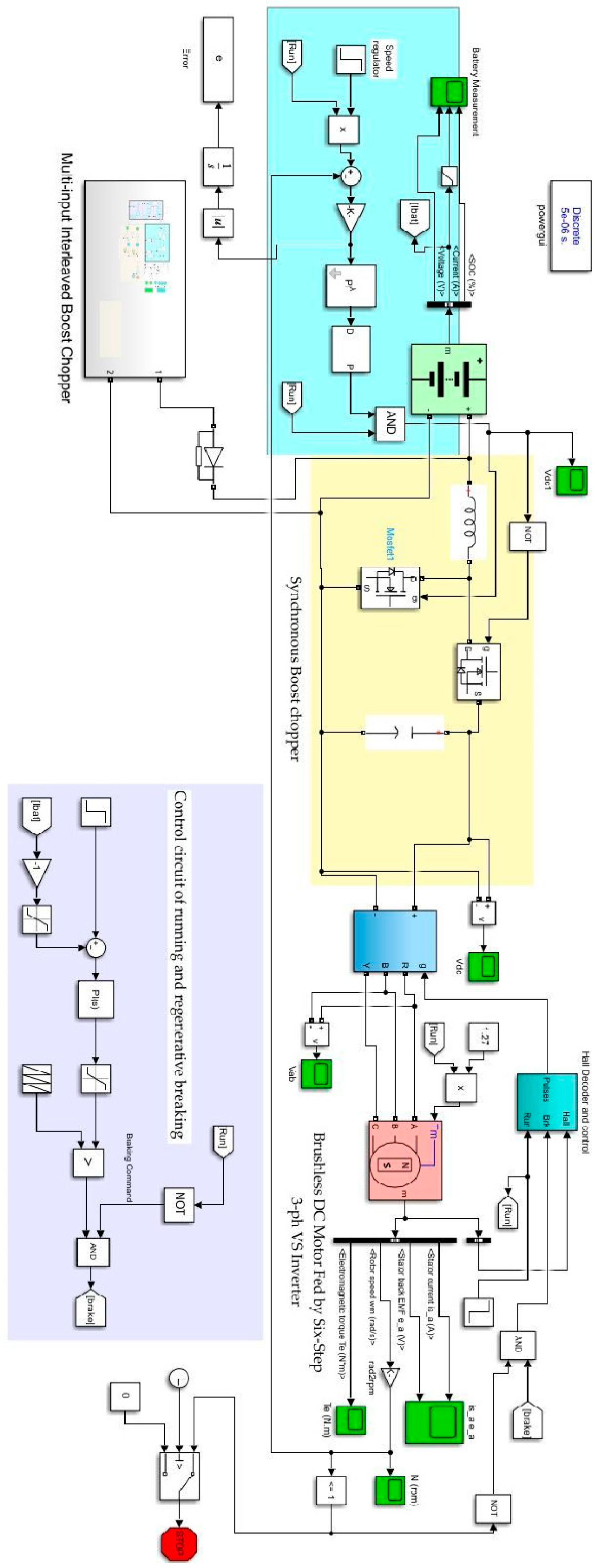
The proposed strategy employs an optimized fractional-order proportional–integral (FoPI) controller to mitigate steady-state variations, oscillations, undershoots, and overshoots, thereby enhancing the effectiveness of speed control and regenerative braking. The Simulink model of the proposed system is provided in Figure A1.
Battery-charging voltage control of EV
For charging, the capacity of the battery is 60 kWh, and the controlled power supply of 24 kW provides 600 V in rated voltage for charging the battery. Thus, it will take less than 2 h to charge from 30% of SOC to 100% full charge. The vehicle can run up to 390 km once it is fully charged. But it is a challenge to maintain the 600 V rated voltage during charging while the input power is supplied through renewable sources.
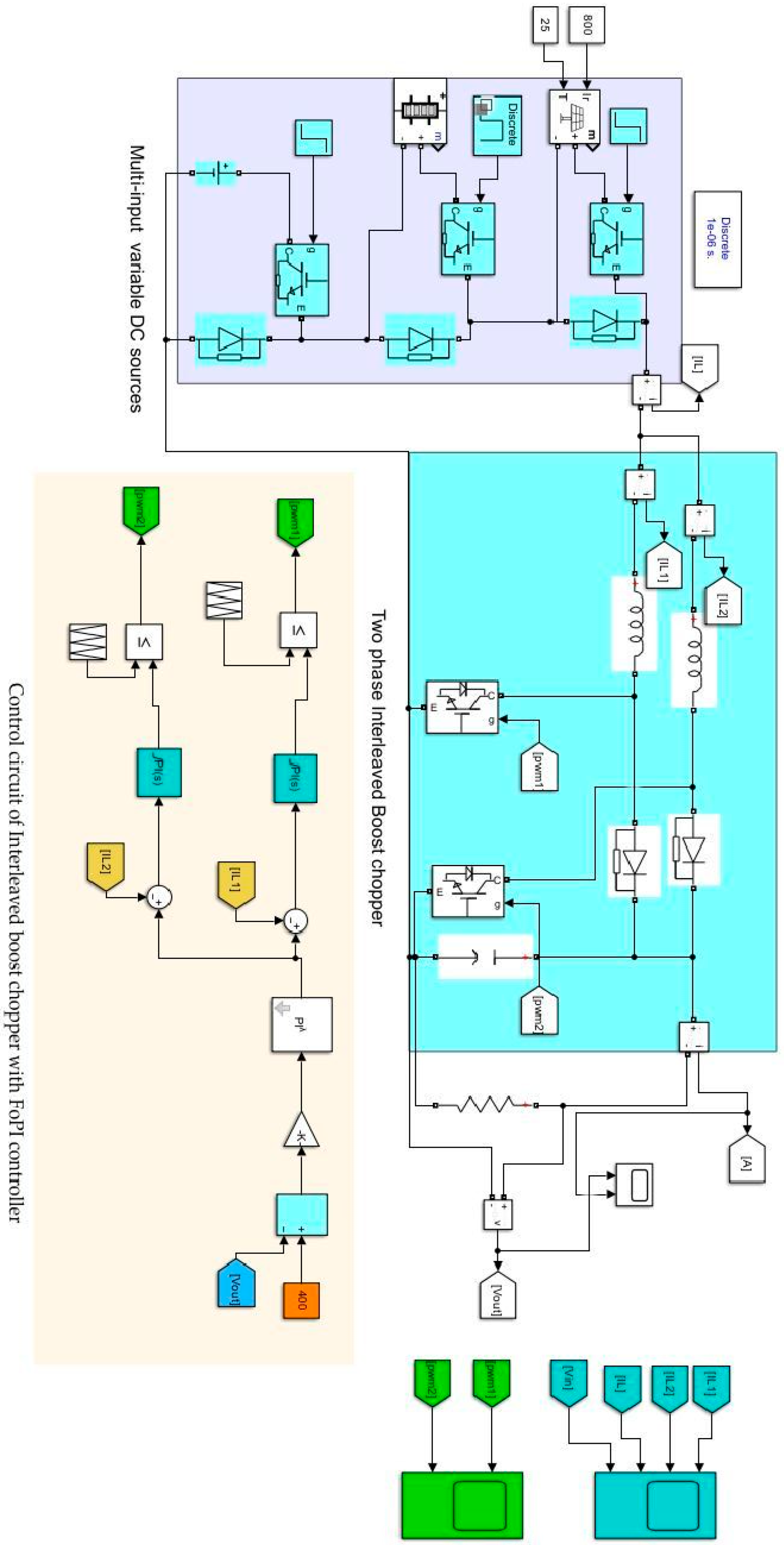
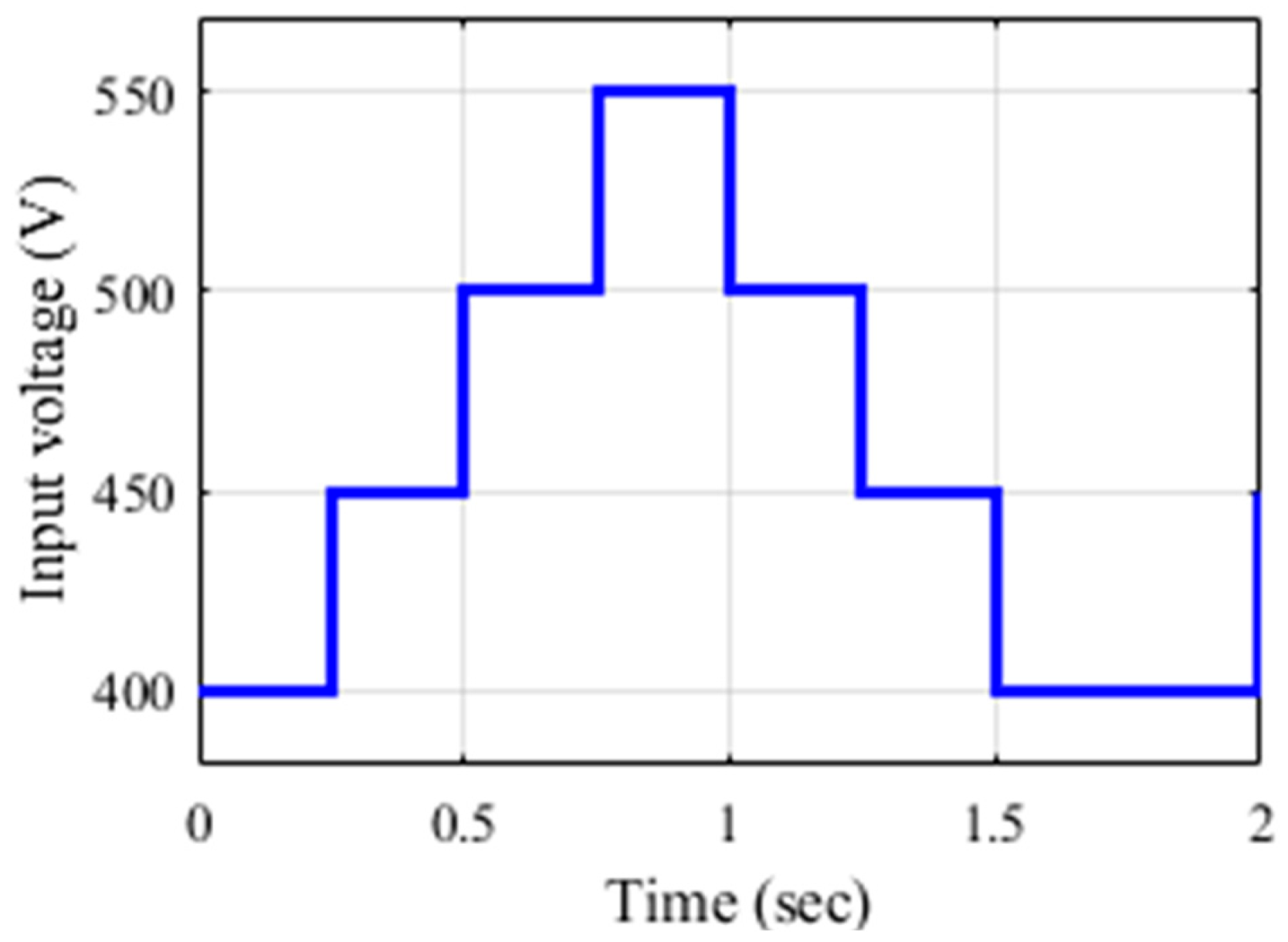
The Simulink models of the interleaved boost chopper with variable sources are presented in Figure A2. In this paper, we considered that the input voltage varies from 400 V to 550 V, with a step of 50 V per 0.25 s in increasing and decreasing order. The input voltage variation is shown in Figure 5. The mathematical analysis and control of the interleaved boost chopper are provided in detail in [25,26], respectively.
The parameters of different components are provided in Table 1.

4.1. Interleaved Boost Chopper for Effective Battery Charging Using Tuned PI and FoPI Controllers

The control strategy includes PI and FoPI controllers tuned with the AHHO algorithm.

4.1.1. Using PI Controllers Tuned with Ziegler–Nichols (Z-N) Method

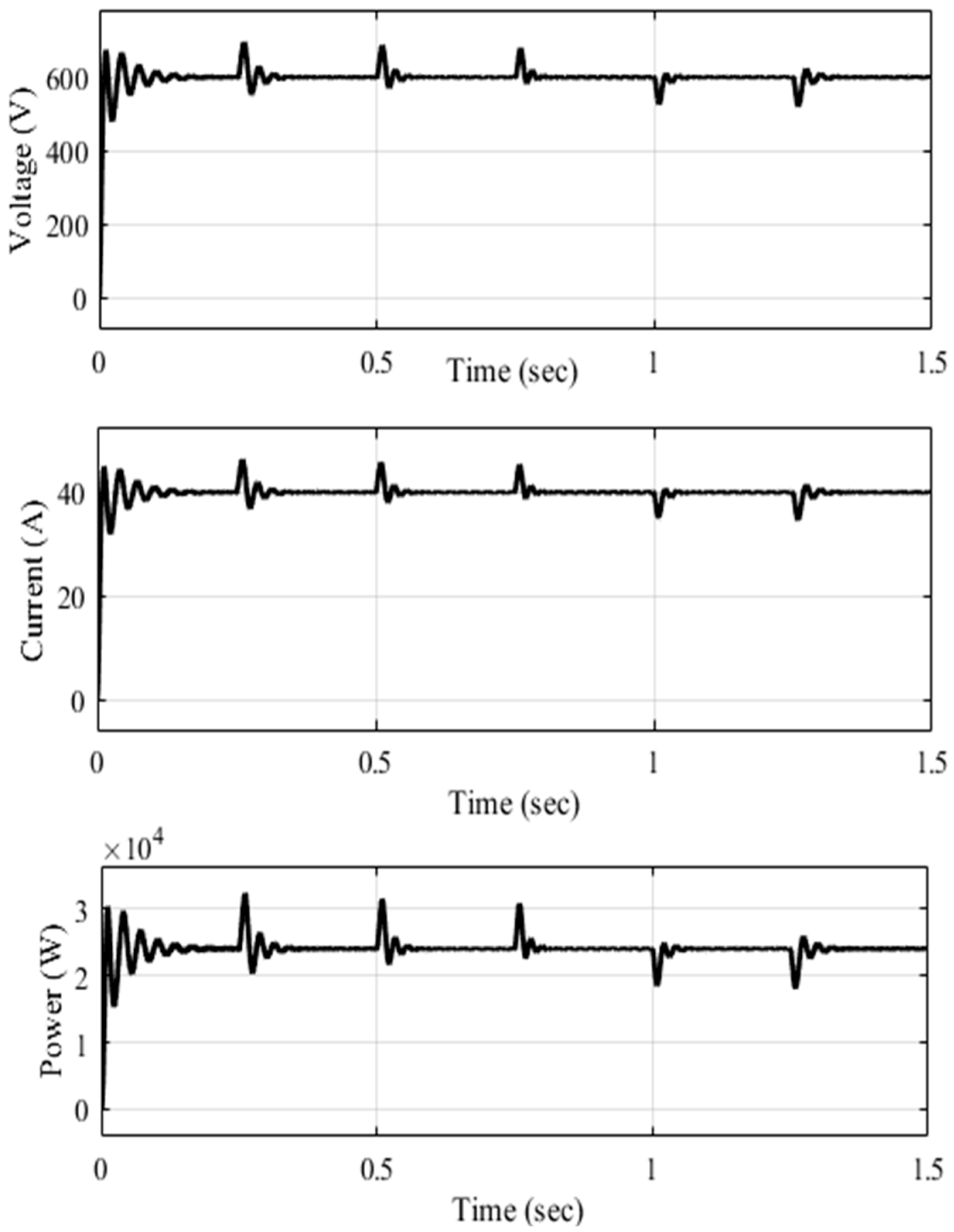
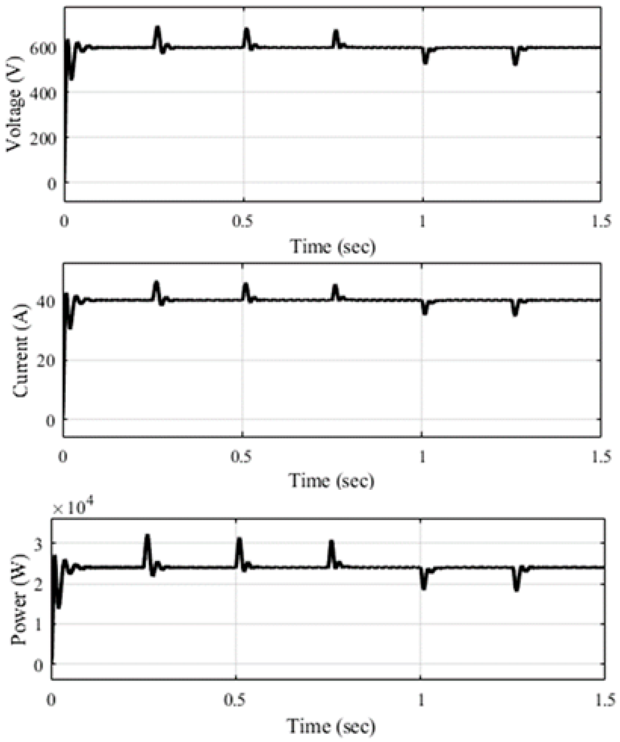
Figure 6 shows the output voltage, current, and power characteristics for charging batteries with PI controllers tuned with the Ziegler–Nichols (Z-N) method. From the graph, the chopper can provide the exact desired voltage and current of 600 V and 40 A.
However, many oscillations occur, in addition to longer transient times, when any changes in input voltages are observed. A similar waveform is also realized for the output power.

4.1.2. Using PI Controllers Tuned with AHHO Algorithm

Further, the PI controller is tuned with the Arithmetic Harris Hawks Optimization (AHHO) algorithm. The parameters related to the PI controller and AHHO are summarized in Table 2.
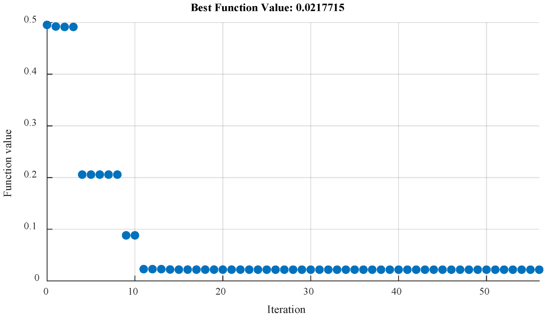
Figure 7 shows that oscillations are reduced to a great extent, and transient time and ripples are also reduced when this PI controller is tuned by AHHO. The fitness curve shows a reduced best error function value of 0.059. The gain values of the PI controller are K p = 0.033 and K i = 60.32 when using the Z-N method and K p   = 0.000213 and K i   = 52.5261 when tuned with the AHHO algorithm. The convergence plot shows that AHHO converges with a minimal iteration number of 10 and with a best error function value of 0.02177, as shown in Figure 8.

4.1.3. Using FoPI Controllers Tuned with AHHO Algorithm

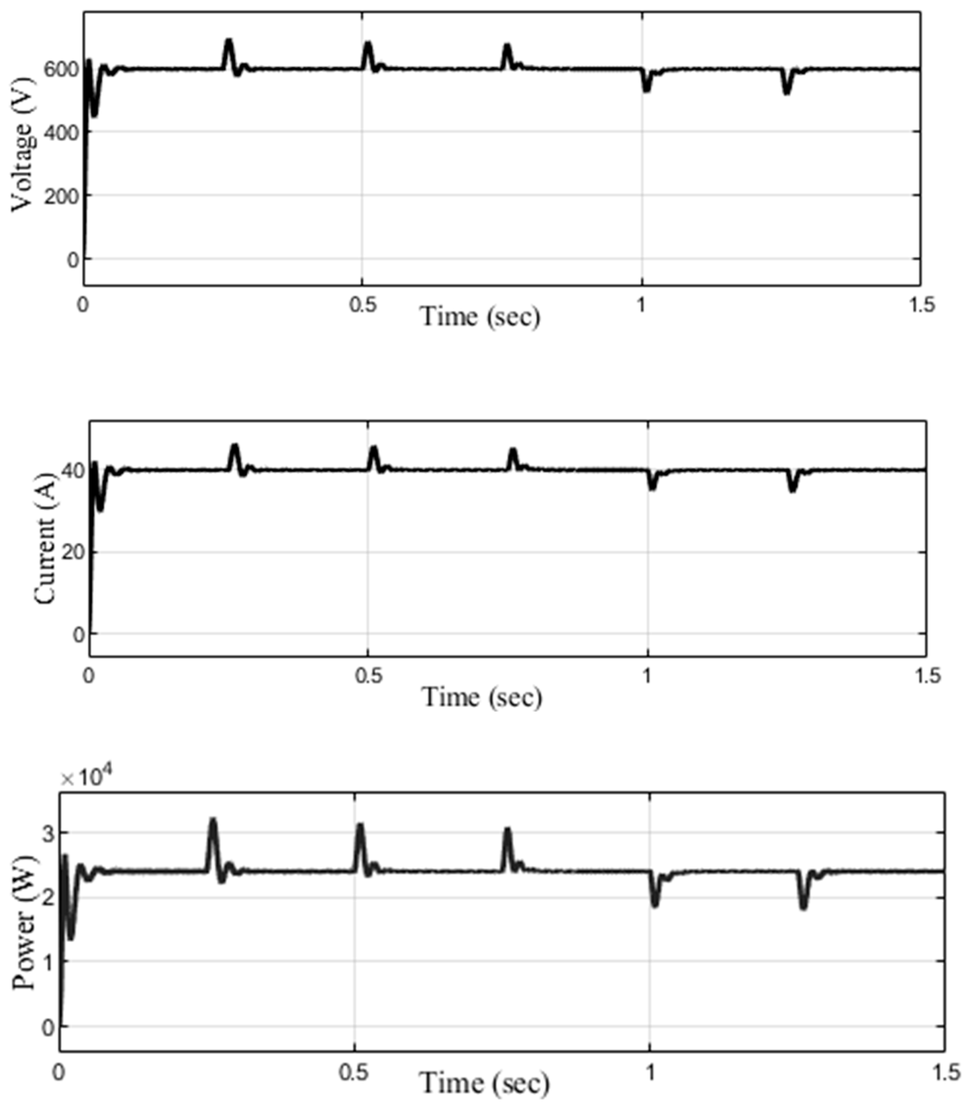
Further, to improve the response of the converter, we introduced an FoPI controller and optimized an extra parameter of λ using the AHHO algorithm. Here, K p = 0.00432, K i = 47.165, and λ = 0.9254 are the optimized parameter values for the FoPI controller. In this case, we can see a substantial change in the output responses, and the ripples are almost removed. It has very low transient times, with fewer spikes during changes in input voltage, and it accurately provides the desired voltages, currents, and power. The waveforms are shown in Figure 9. The convergence plot of the error function of AHHO for tuning the FoPI controller is shown in Figure 10. It shows that the convergence occurring at the 10th iteration had the best error function value of 0.01158.

4.1.4. Transient Analysis of the System

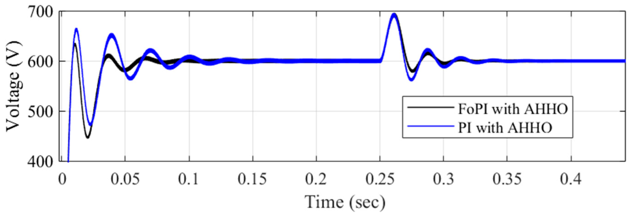
Transient analysis assesses the circuit’s temporal response subsequent to a rapid alteration in input voltage. The rate at which transitory effects diminish and the system attains a steady state is mostly influenced by the controller’s design and parameters. The main outcomes of Figure 6, Figure 7, and Figure 9 are compared and shown in Table 3. The comparison is carried out on the parameters of maximum overshoot (% Mp), settling time (ts), and reach time (Treach), i.e., the time required to overcome the transient effect and the time required to reach the steady-state value during the initial state and intermediate state while changes in input voltages take place. As the waveforms of the AHHO-tuned PI and FoPI are similar, a detailed comparison figure is shown in Figure 11, where the voltage waveforms of the PI controller tuned with AHHO and the FoPI controller tuned with AHHO are compared. The differences are clearly visible: The intermittent transient effect recovers quickly for both cases, but the initial transient is longer when using the PI controller. The graphical representation of the performance of the controller is shown in Figure 12.

4.2. Energy Recovery Through Regenerative Braking Using FoPID Controllers

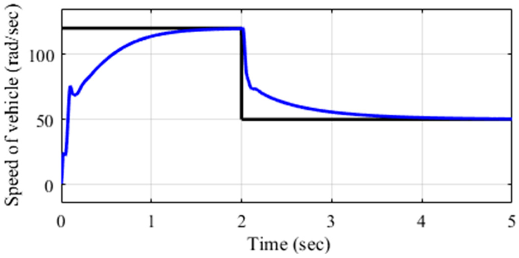
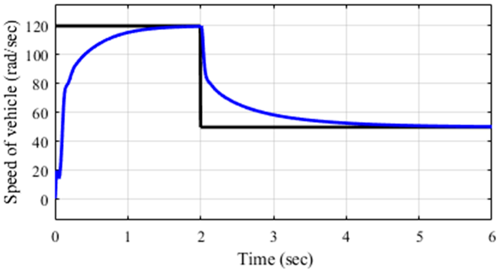
Here, a regenerative braking system with an FoPID controller is also suggested for energy recovery using BLDC motors. The proposed approach for braking involves utilizing a DC–DC synchronous boost chopper linked to a multi-cell battery system to implement variable stator voltages via a three-phase voltage source inverter. A 3-phase voltage source inverter (VSI) is employed to supply power to the three phases of a brushless direct current (BLDC) motor. We conducted simulations to evaluate the proposed braking mechanism within the MATLAB Simulink 2023b environment. The simulation outcomes illustrate the feasibility and efficacy of the suggested regenerative braking technique. This study also presents the most straightforward method for employing a BLDC motor in regenerative braking, which can enhance the range of relatively lightweight electric vehicles. The method is structured to facilitate a steady and smooth acceleration from rest to 120 rad/s. Braking is initiated at the 2nd second. The simulation results show that a smooth reduction in speed is achieved with the FoPID controller in regenerative braking, as shown in Figure 13. Also, the same experiment is conducted using PID controllers tuned with the Z-N method, and the results are shown in Figure 14. Here, a notch in speed is shown at the initial phase, which implies a jerk in real time, and in comparison with PID, the FoPID controller shows smooth acceleration and braking.
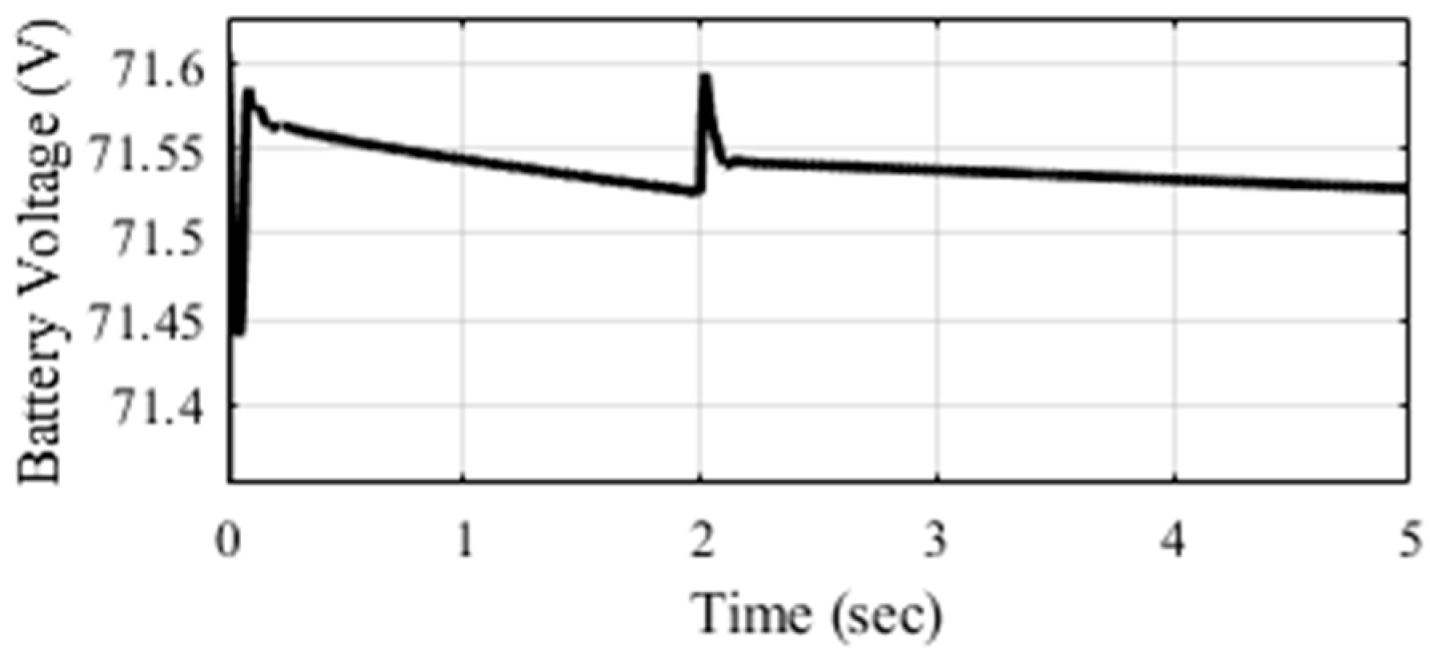
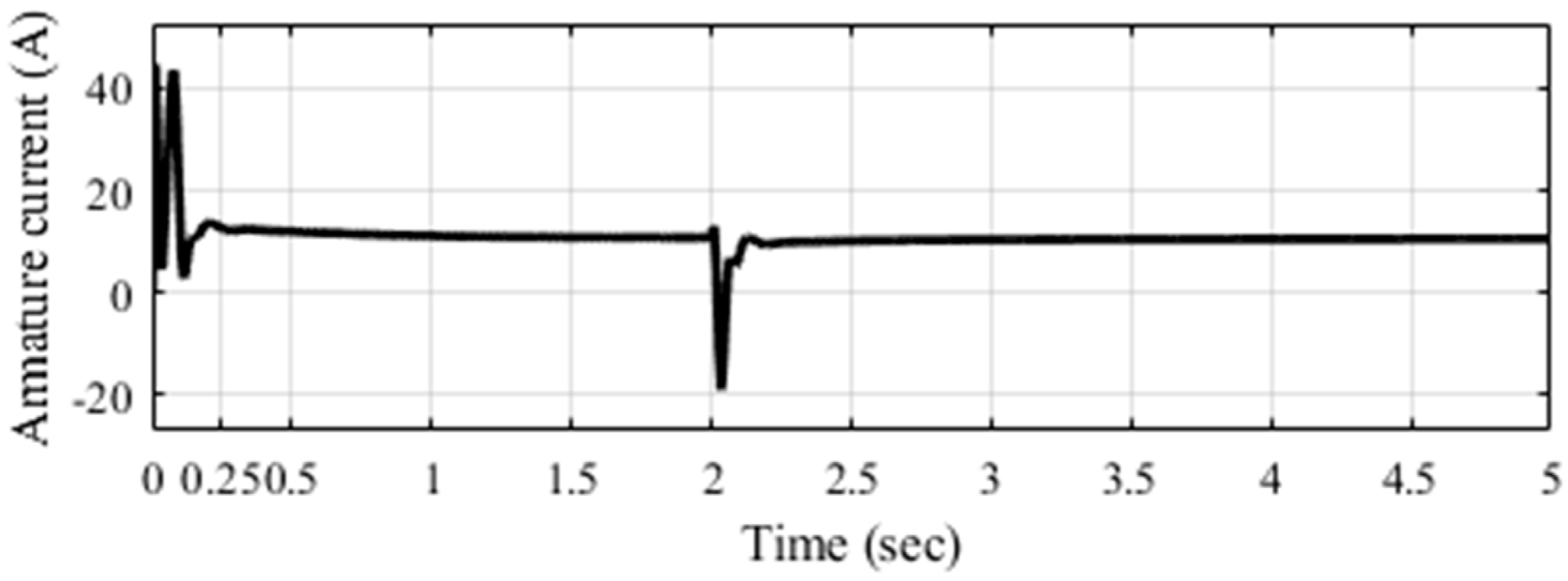
Figure 15 illustrates that as the vehicle operates, the battery’s voltage gradually diminishes from 71.6 V. Upon the application of brakes after 2 s, there is a sudden increase in voltage, attributable to regenerative braking. Subsequently, throughout the duration of braking, the battery voltage remains stable at 71.52 V. In Figure 16, the battery current remains constant, supplying a steady current to the motor during the motoring mode. During braking, the current becomes negative as the generating mode commences, and due to regenerative braking, the battery’s current rapidly increases, facilitating the charging of the battery in the generating mode.
The slope of the decline in the % SOC of the battery is elevated during motoring operations, and with the initiation of braking, the slope is gradually reduced, as illustrated in Figure 17. All these waveforms necessitate excellent energy recovery during regenerative braking.
The electrical torque that is produced at the rotor for propelling the vehicle is shown in Figure 18. Initially, the motor needs high starting torque to propel the vehicle, and gradually, the torque is reduced once the speed of the vehicle is set. In this waveform, the high initial torque is observed, and soon after, it is reduced and becomes constant up to 2 s until braking is applied. During braking, the torques becomes negative as the generating mode is initiated, and soon after, it reaches constant torque as the vehicle is controlled under the constant torque mode. For BLDC motors, the motor’s torque is proportional to the rotor or armature current. Hence, similar waveforms are found for the rotor current, as shown in Figure 19.
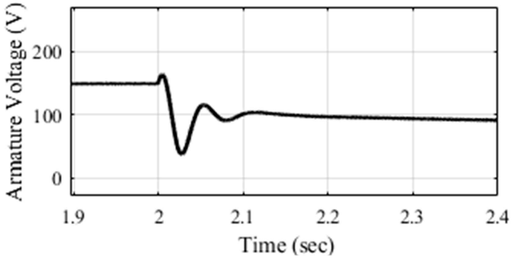
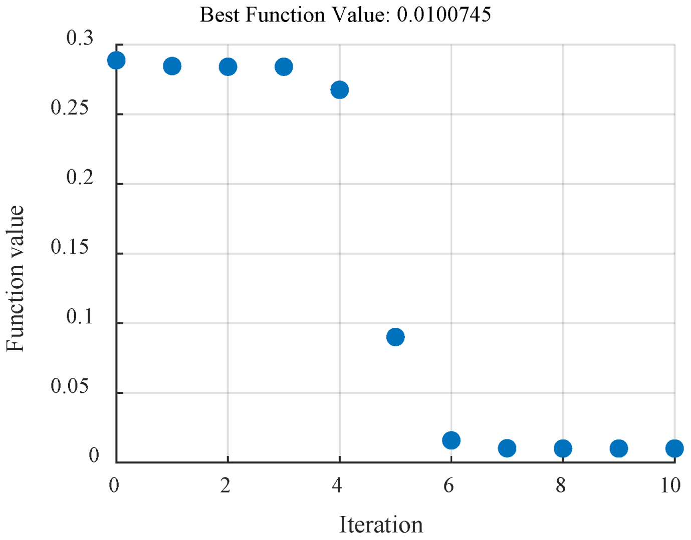
Further, Figure 20 shows that, initially, 150 V is induced as the armature voltage in the rotor of the BLDC, and this continues until braking is applied. At the 2nd second, when braking is applied, a small increase in voltage is seen due to transient effects, and soon after, the voltage is reduced, but due to regenerative braking, the voltage increases again and reaches 100 V due to the generating mode. In the regenerative mode, the motor behaves as a generator and produces 100 V. The FoPID-based controller provides fast transient responses; thus, the voltage reaches a steady state within 0.1 s of applied braking. Hence, it can be said that the FoPID controller is sufficiently capable of recovering energy from regenerative braking. The gains in the FoPID parameters are as follows: K p = 0.004914188, K i = 0.018691, K d = 0.000287, λ = 1.01562, and µ = 1.05126. This FoPID controller is tuned using AHHO. The convergence plot is shown in Figure 21. It is observed in Figure 21 that the best error function value is achieved as 0.01 at the eighth iteration.

5. Conclusions

This study introduced a method for enhancing battery-charging capabilities in electric vehicles and effective energy restoration during regenerative braking. The input power is supplied from renewable sources, though it exhibits a fluctuating nature and has reliability issues. We used PI and FoPI controllers to resolve these issues and provided stable and desired outputs with minimal transient effects. Arithmetic Harris Hawks Optimization is used to tune PI and FoPI controllers. A high-power interleaved boost chopper is used as a power converter to charge the battery. Here, the input voltage varied from 400 to 550 V, and the desired voltage is set at 600 V. It was shown from the output waveforms that the desired power at the rated voltage was achieved, with fewer ripple and transient effects. The converter controlled by the FoPI controller provides faster steady-state responses. The whole system is simulated through MATLAB Simulink 2023b. On the other hand, the AHHO algorithm is also employed to fine-tune the PID and FoPID controllers for optimal energy recovery. It was shown through the simulation results that, during regenerative braking, the decreasing slope of the % SOC was improved, the battery’s current was enhanced, and the battery voltage, which decreased suddenly, increased to full voltage. As a result, it is reasonable to assume that some energy is recovered and reused to charge the battery, ensuring that the electric vehicle can run for an extended period of time.
Addressing this study’s shortcomings should be a focus of future research. Improving the speed regulation of BLDC motors and optimizing energy recovery during braking involves investigating the adjustment of variables in the FoPI controller, incorporating sophisticated machine learning approaches like deep learning or reinforcement learning. Research should also focus on adaptive control based on real-time factors, and performance could be enhanced by incorporating vehicle dynamics. Researchers can improve the overall performance and robustness of vehicles by implementing these advanced control systems.

Author Contributions

Conceptualization, D.S. and S.M.; methodology, D.S. and S.M.; formal analysis and investigation, C.B. and H.K.S.; writing—original draft preparation, D.S. and S.M.; writing—review and editing, C.B. and H.K.S.; funding acquisition, H.K.S.; resources, S.M. and C.B.; supervision, C.B. All authors have read and agreed to the published version of the manuscript.

Funding

This research received no external funding.

Data Availability Statement

The original contributions presented in this study are included in the article. Further inquiries can be directed to the corresponding authors.

Acknowledgments

We are indebted to the anonymous reviewers and the Editor-in-Chief for giving us the opportunity to submit the revised version of our manuscript.

Conflicts of Interest

The authors declare that there are no conflicts of interest among the authors.

Appendix A

In this section, we present the Simulink model of the proposed system and battery-charging system in the following figures. Figure A1 shows the whole proposed scheme and the subsystem of Multi-input interleaved boost chopper of Figure A1 is shown in Figure A2.
Figure A1. Simulink model of the proposed system.
Fractalfract 09 00525 g0a1
Figure A2. Simulink model of battery-charging system with renewable sources.
Fractalfract 09 00525 g0a2

References

  1. Al-Shariff, S.M.; Alam, M.S.; Ahmad, Z.; Ahmad, F. Smart transportation system: Mobility solution for smart cities. In 2nd Smart Cities Symposium (SCS 2019); IET: Stevenage, UK, 2019; pp. 6–59. [Google Scholar]
  2. Leviakangas, P.; Kinnunen, T.; Kess, P. The electric vehicles ecosystem model-construct, analysis and identification of key challenges. Manag. Glob. Transit. 2014, 12, 253–277. [Google Scholar]
  3. Mohanraj, D.; Gopalakrishnan, J.; Chokkalingam, B.; Mihet-Popa, L. Critical aspects of electric motor drive controllers and mitigation of torque ripple—Review. IEEE Access 2022, 10, 73635–73674. [Google Scholar] [CrossRef]
  4. Tuttle, D.P.; Baldick, R. The evolution of plug-in electric vehicle-grid interactions. IEEE Trans. Smart Grid 2012, 3, 500–505. [Google Scholar] [CrossRef]
  5. Ogura, K. Kolhe Battery Technology for Electric Vehicle; Kawasaki Heavy Industries, Ltd.: Kobe, Japan; University of Agder: Kristiansand, Norway, 2017. [Google Scholar]
  6. Adedeji, B.P. Electric vehicles survey and a multifunctional artificial neural network for predicting energy consumption in all-electric vehicles. Results Eng. 2023, 19, 101283. [Google Scholar] [CrossRef]
  7. Naqvi, S.S.A.; Jamil, H.; Iqbal, N.; Khan, S.; Lee, D.I.; Park, Y.C.; Kim, D.H. Multi-objective optimization of PI controller for BLDC motor speed control and energy saving in Electric Vehicles: A constrained swarm-based approach. Energy Rep. 2024, 12, 402–417. [Google Scholar] [CrossRef]
  8. da Dantas, A.D.O.S.; de Dantas, A.F.O.A.; Campos, J.T.L.S.; de Almeida Neto, D.L.; Dórea, C.E.T. PID control for electric vehicles subject to control and speed signal constraints. J. Control Sci. Eng. 2018, 2018, 6259049. [Google Scholar] [CrossRef]
  9. Baidya, D.; Dhopte, S.; Bhattacharjee, M. Sensing System Assisted Novel PID Controller for Efficient Speed Control of DC Motors in Electric Vehicles. IEEE Sens. Lett. 2023, 7, 1–4. [Google Scholar] [CrossRef]
  10. Feng, N.; Yong, J.; Zhan, Z. A direct multiple shooting method to improve vehicle handling and stability for four hub-wheel-drive electric vehicle during regenerative braking. Proc. Inst. Mech. Eng. Part D J. Automob. Eng. 2020, 234, 1047–1056. [Google Scholar] [CrossRef]
  11. Geng, C.; Ning, D.; Guo, L.; Xue, Q.; Mei, S. Simulation research on regenerative braking control strategy of hybrid electric vehicle. Energies 2021, 14, 2202. [Google Scholar] [CrossRef]
  12. Aksjonov, A.; Ricciardi, V.; Augsburg, K.; Vodovozov, V.; Petlenkov, E. Hardware-in-the-Loop test of an Open-Loop fuzzy control method for decoupled Electrohydraulic Antilock braking system. IEEE Trans. Fuzzy Syst. 2021, 29, 965–975. [Google Scholar] [CrossRef]
  13. Lv, C.; Zhang, J.; Li, Y.; Yuan, Y. Mechanism analysis and evaluation methodology of regenerative braking contribution to energy efficiency improvement of electrified vehicles. Energy Convers. Manag. 2015, 92, 469–482. [Google Scholar] [CrossRef]
  14. Li, L.; Li, X.; Wang, X.; Liu, Y.; Song, J.; Ran, X. Transient switching control strategy from regenerative braking to anti-lock braking with a semi-brake-by-wire system. Veh. Syst. Dyn. 2016, 54, 231–257. [Google Scholar] [CrossRef]
  15. Jamadar, N.M.; Jadhav, H.T. A review on braking control and optimization techniques for electric vehicle. Proc. Inst. Mech. Eng.-Part D J. Automob. Eng. 2021, 235, 2371–2382. [Google Scholar] [CrossRef]
  16. Vodovozov, V.; Raud, Z.; Petlenkov, E. Review on braking energy management in electric vehicles. Energies 2021, 14, 4477. [Google Scholar] [CrossRef]
  17. Ivanov, V.; Savitski, D.; Shyrokau, B. A Survey of traction control and Antilock braking systems of full electric vehicles with Individually controlled electric motors. IEEE Trans. Veh. Technol. 2015, 64, 3878–3896. [Google Scholar] [CrossRef]
  18. Zhang, J.; Yang, Y.; Hu, M.; Yang, Z.; Fu, C. Longitudinal-vertical comprehensive control for four-wheel drive pure electric vehicle considering energy recovery and ride comfort. Energy 2021, 236, 121417. [Google Scholar] [CrossRef]
  19. Saleem, O.; Rizwan, M.; Khizar, A.; Ahmad, A. Augmentation of Fractional-Order PI Controller with Nonlinear Error-Modulator for Enhancing Robustness of DC-DC Boost Converters. J. Power Electron. 2019, 19, 835–845. [Google Scholar] [CrossRef]
  20. Saleem, O.; Ali, S.; Iqbal, J. Robust MPPT Control of Stand-Alone Photovoltaic Systems via Adaptive Self-Adjusting Fractional Order PID Controller. Energies 2023, 16, 5039. [Google Scholar] [CrossRef]
  21. Saleem, O.; Shami, U.T.; Mahmood-ul-Hasan, K. Time-optimal control of DC-DC buck converter using single-input fuzzy augmented fractional-order PI controller. Int. Trans. Electr. Energy Syst. 2019, 29, e12064. [Google Scholar] [CrossRef]
  22. Sinha, D.; Ghosh, S.; Majumdar, S.; Bandyopadhyay, C.; Bhattacharya, S. Effective Control of Speed and Regenerative Braking in Electric Vehicles Utilizing Fractional Order PI Controller. In Proceedings of the 2025 IEEE 1st International Conference on Smart and Sustainable Developments in Electrical Engineering (SSDEE), Dhanbad, India, 28 February–2 March 2025; IEEE, 2025; pp. 1–6. [Google Scholar]
  23. Heidari, A.A.; Mirjalili, S.; Faris, H.; Aljarah, I.; Mafarja, M.; Chen, H. Harris Hawks Optimization: Algorithm and Applications. Future Gener. Comput. Syst. 2019, 97, 849–872. [Google Scholar] [CrossRef]
  24. Jaber, M.M.; Jameel, S.S.; Khudhair, H.N. An Arithmetic Optimization Algorithm-Based Harris Hawks Optimization for Global Optimization. Machines 2022, 10, 602. [Google Scholar]
  25. Pal, S.; Sinha, D.; Das Mahapatra, M.; Majumder, S.; Bhattacharya, S.; Bandyopadhyay, C. Performance evaluation of multi-Input Interleaved Boost Converter with tuned PI controller. Chin. J. Electr. Eng. 2024, 10, 119–128. [Google Scholar] [CrossRef]
  26. Sinha, D.; Mahapatra, M.D.; Pal, S.; Majumder, S.; Bhattacharya, S.; Bandyopadhyay, C. Adaptation of fractional-order PI controller for a variable input interleaved DC–DC boost converter using particle swarm optimization with parametric variation. IFAC J. Syst. Control 2025, 32, 100301. [Google Scholar] [CrossRef]
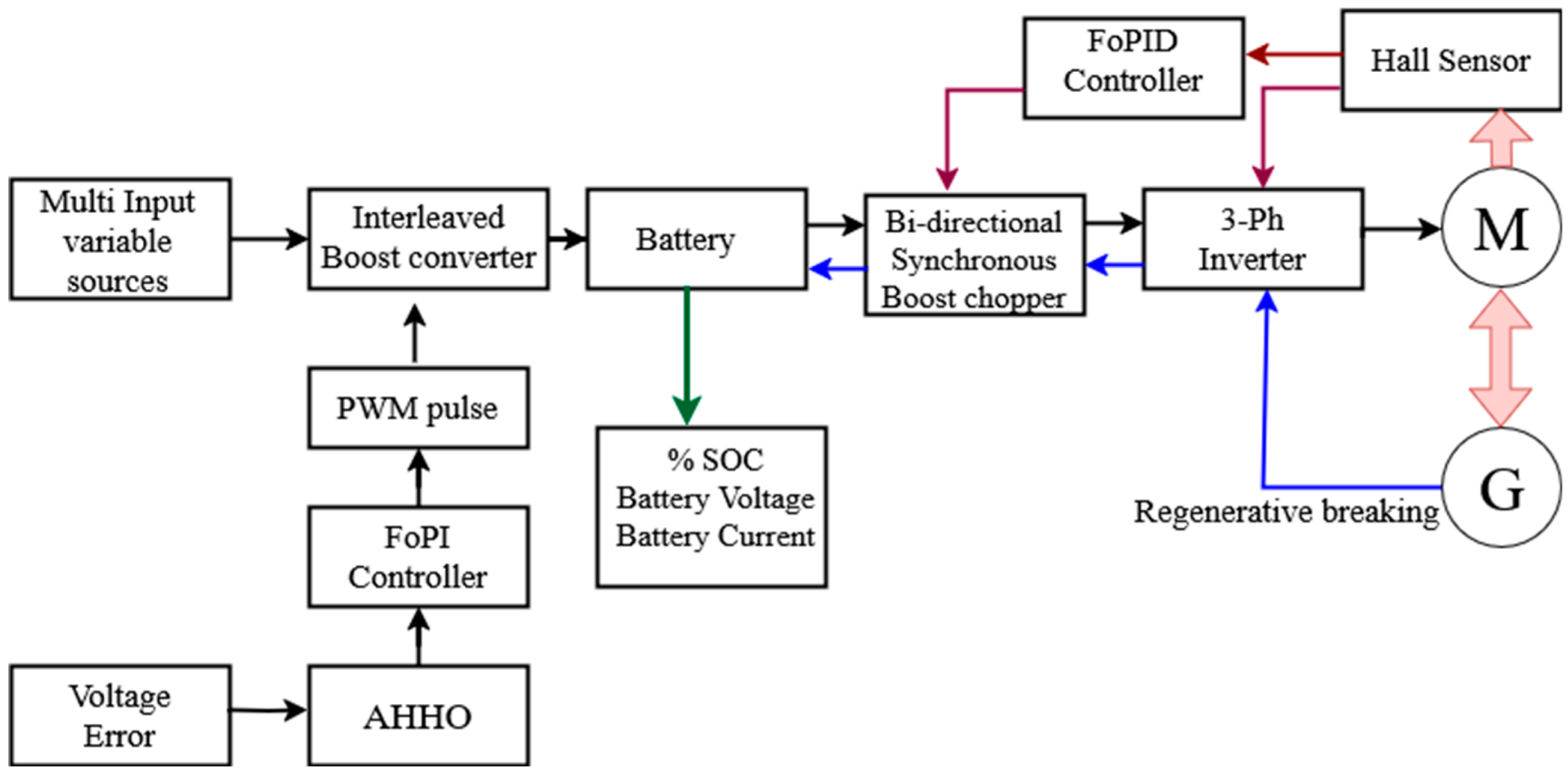
Figure 1. Block diagram of the proposed scheme for effective battery charging and regenerative braking.
Fractalfract 09 00525 g001
Figure 2. Block diagram of multi-input interleaved boost converters for charging batteries.
Fractalfract 09 00525 g002
Figure 3. Block diagram of energy recovered through regenerative braking.
Fractalfract 09 00525 g003
Figure 4. The flowchart of the AHHO algorithm.
Fractalfract 09 00525 g004
Figure 5. Input voltage variation.
Fractalfract 09 00525 g005
Figure 6. Output voltage, current, and power characteristics using PI tuned with the Z-N method.
Fractalfract 09 00525 g006
Figure 7. Output voltage, current, and power characteristics using PI tuned with AHHO algorithm.
Fractalfract 09 00525 g007
Figure 8. Convergence plot of the error function of AHHO for tuning the PI controller.
Fractalfract 09 00525 g008
Figure 9. Output voltage, current, and power characteristics using FoPI tuned with AHHO algorithm.
Fractalfract 09 00525 g009
Figure 10. Convergence plot of the error function of AHHO algorithm for tuning the FoPI controller.
Fractalfract 09 00525 g010
Figure 11. Comparison of voltage waveforms using AHHO implementation in PI and FoPI controllers.
Fractalfract 09 00525 g011
Figure 12. Performance analysis of the controller.
Fractalfract 09 00525 g012
Figure 13. Speed of vehicle during acceleration and braking applied using FoPID controllers.
Fractalfract 09 00525 g013
Figure 14. Speed of vehicle during acceleration and braking applied using PID controllers.
Fractalfract 09 00525 g014
Figure 15. Characteristics of battery voltage during running and braking operations.
Fractalfract 09 00525 g015
Figure 16. Characteristics of battery current during running and braking operations.
Fractalfract 09 00525 g016
Figure 17. Battery SOC variation during running and braking operations.
Fractalfract 09 00525 g017
Figure 18. Characteristics of electrical torque during motoring and regenerative braking modes.
Fractalfract 09 00525 g018
Figure 19. Armature or rotor current waveform during motoring and regenerative braking modes.
Fractalfract 09 00525 g019
Figure 20. Induced armature voltage waveform during motoring and regenerative braking modes.
Fractalfract 09 00525 g020
Figure 21. Convergence plot of the error function of AHHO for tuning FoPID controllers.
Fractalfract 09 00525 g021
Table 1. Parameters of different components.
Battery Specification
Type of BatteryLithium Ferro Phosphate
Nominal voltage (V)72
Rated capacity (Ah)400
Initial state of charge (% SOC)50
Cut-off voltage (V)54
Fully charged voltage (V)78.4
Nominal discharge current (A)30
Internal resistance (Ohms)0.0048
Capacity (Ah) at nominal voltage46.54
DC–DC Interleaved Boost Chopper Specification (For Battery Charging)
Output Power rating (kW)24
Operating Frequency (kHz)5
Inductance (H)0.0199
Capacitance (uF)312
Output voltage (V)600
Output current (A)40
Input voltage variation (V)400–550
Synchronous Boost Chopper Specification (For Regenerative Braking)
Inductance (H)0.03
Input filter capacitance (mF)2.9
Output filter capacitance (mF)2.9
Initial voltage stored at output capacitance (V)240
3-phase BLDC Motor Specification
Stator-phase resistance (Ohm)0.47
Stator-phase induction (H)0.000595
Inertia constant0.0003
Viscous damping0.00030345
Pole pair4
Rotor flux position when Theta = 090° behind-phase-A (modified park) transformation
Table 2. Parameters of AHHO algorithm.
CategoryParametersValues
PI controller K p , K i Range: 0.0001–100
Search spaceLower and upper bounds[0.0001, 0.0001], [100, 100]
AHHO setupPopulation size30
Max iterations100
Random coefficients r 1 , r 2 , q , r [ 0 ,   1 ]
Optimization logic Escape   energy   E From 1 to −1 over iterations
ObjectiveFitness functionIAE
Table 3. Comparative analysis of the constraints of the output voltage waveform.
Constraints
Method% MpTs (s)Treach (s) (Initial)Treach (s)
(Intermediate)
PI-ZN13.330.090.15630.0938
PI-AHHO8.330.060.10.065
FoPI-AHHO5.00.030.06250.06
Disclaimer/Publisher’s Note: The statements, opinions and data contained in all publications are solely those of the individual author(s) and contributor(s) and not of MDPI and/or the editor(s). MDPI and/or the editor(s) disclaim responsibility for any injury to people or property resulting from any ideas, methods, instructions or products referred to in the content.