Article

Discrete-Time Fractional-Order Sliding Mode Attitude Control of Multi-Spacecraft Systems Based on the Fully Actuated System Approach

College of Automation Engineering, Nanjing University of Aeronautics and Astronautics, Nanjing 211106, China
*
Author to whom correspondence should be addressed.
Fractal Fract. 2025, 9(7), 435; https://doi.org/10.3390/fractalfract9070435
Submission received: 4 June 2025 / Revised: 25 June 2025 / Accepted: 27 June 2025 / Published: 1 July 2025
(This article belongs to the Special Issue Fractional Dynamics and Control in Multi-Agent Systems and Networks)

Abstract

In practical applications, most systems operate based on digital signals obtained through sampling. Applying fractional-order control to spacecraft attitude control is meaningful for achieving better performance, especially in the coordination of the multi-spacecraft attitude system. In this paper, a discrete-time fractional-order sliding mode attitude control problem is studied for multi-spacecraft systems based on the fully actuated system approach. Firstly, a discrete-time disturbance observer based on the fractional-order theory is constructed to estimate the disturbance. Secondly, a discrete-time fractional-order sliding mode controller is designed by combining the transformed fully actuated discrete-time system and the disturbance observer. Subsequently, every spacecraft can track the desired attitude under the designed controller. Finally, the simulation results show that the developed control method achieves faster convergence, smaller overshoot, and higher control accuracy.

1. Introduction

Considering the future development needs of space missions, the control of multi-spacecraft systems has received extensive attention in the past decade. As people aim to explore more distant destinations and undertake complex tasks such as satellite servicing and formation flying, the effective coordination and control of multi-spacecraft systems have become critical. For instance, Sui and Duan et al. [1] investigated a novel integral sliding mode approach to converge tracking errors within a fixed time. Cui and Zhang et al. [2] designed a fixed-time adaptive controller for multiple spacecraft systems on a directed graph. Other scholars have made many profound contributions to the attitude cooperative control of multi-spacecraft systems [3,4,5,6]. Furthermore, some remarkable advances have been achieved in broader applications of multi-agent systems. In [7], an unknown-input-observer scheme was proposed to resolve delay issues in multi-UAV systems, achieving robust H consensus tracking. Wu and Sun et al. [8] designed a PD-like consensus tracking algorithm to achieve quick convergence under noisy binary communication and time-varying leader states. Chang and Yang et al. [9] developed a formation strategy for a heterogeneous system, improving formation maintenance and obstacle avoidance capabilities. These studies investigate multi-agent system control through diverse control approaches, spanning both continuous-time and discrete-time controllers.
Although traditional continuous-time controller designs are relatively convenient, control signals and system state variables are acquired through sampled data in most practical implementations [10]. Therefore, it is necessary to study discrete-time controllers. The development of discrete-time spacecraft attitude systems has received relatively less attention. Nevertheless, some efforts have been devoted to this field. In [11], the scholars studied a discrete-time state observer for a rigid-spacecraft system. Lee and Park et al. [12] presented an optimal formation tracking control method on the basis of discrete-time Hamilton–Jacobi theory. For a spacecraft with momentum and control constraints, Phogat and Chatterjee et al. [13] addressed the attitude optimal control problem. Discrete-time control has the advantages of lower cost in implementation and relatively simpler computation. Therefore, it is meaningful to further investigate discrete-time spacecraft attitude systems.
However, the spacecraft attitude system is a coupled nonlinear system, which poses challenges for relevant controller design. In response to the issues associated with nonlinear systems, Duan [14] proposed the fully actuated system approach. This approach greatly reduces the complexity of designing controllers for nonlinear systems and enables more flexible and robust controller design. Moreover, Duan [15] pointed out that this approach was not only effective for continuous-time systems but can also be adaptable to discrete-time systems. For example, Wang and Duan et al. [16] designed a predictive controller for a discrete-time nonlinear model based on the fully actuated approach. The discrete-time higher-order fully actuated system approach can reduce the complexity of controller design while enhancing the system’s robustness. Therefore, it is worth extending further research towards discrete-time nonlinear systems through the fully actuated system approach.
Most systems are inevitably subjected to the disturbances during their operation. Therefore, it is necessary to adopt a suitable control method to ensure stability. Under conditions of model inaccuracy and disturbances, PID-based regulation constitutes a widely adopted approach for stabilizing uncertain systems. Model-free controllers offer implementation simplicity and design convenience, particularly in real application systems. However, for systems with well-characterized models, model-based methods are generally preferred to achieve enhanced control precision. Sliding mode control, as a traditional model-based approach in the field of control systems, is well known for its excellent robustness and insensitivity to parameter variations [17,18]. Over the years, many studies have been carried out on sliding mode control methods for spacecraft systems. Chen and Yan et al. [19] proposed a discrete-time sliding mode control law to achieve spacecraft attitude tracking in finite time. For a prescribed time spacecraft attitude tracking problem, a sliding mode controller based on a disturbance observer was proposed to achieve attitude tracking [20]. Tan and Zhang et al. [21] designed an event-triggered sliding mode controller for spacecraft with attitude constraints. In addition, there is a growing need for tighter control of accuracy in the future. For the above requirements, fractional-order control is an effective method. Fractional-order control is based on fractional-order theory and utilizes the historical state information of the system to achieve more accurate control performance [22,23,24,25]. In recent years, considerable advances have been made in the development and application of fractional-order control methods. Sopasakis and Sarimveis [26] utilized discrete-time fractional-order theory in the control field. Sun and Ma et al. [27] designed a discrete-time fractional-order sliding mode for a linear motor tracking problem. Zhang and Yang et al. [28] investigated an optimal setting of the discrete-time fractional-order PID controller. In [29], a fractional-order PI controller for multi-area power systems was designed to achieve better control performance. Gupta and Dei et al. [30] developed a fractional-order PID controller to achieve optimal performance for power systems. Shao and Chen [31] proposed a robust discrete-time fractional-order controller for an unmanned aerial vehicle system. Wu and Liu et al. [32] developed a fractional-order sliding mode control strategy which can achieve a faster attitude coordination speed. As a result, exploring the application of fractional-order control in a multi-spacecraft system is worth further investigation.
Therefore, inspired by the above ideas, a discrete-time fractional-order sliding mode control method based on the fully actuated system approach is studied for a multi-spacecraft attitude system with bounded disturbances in this paper. The main contributions of this paper are summarized as follows:
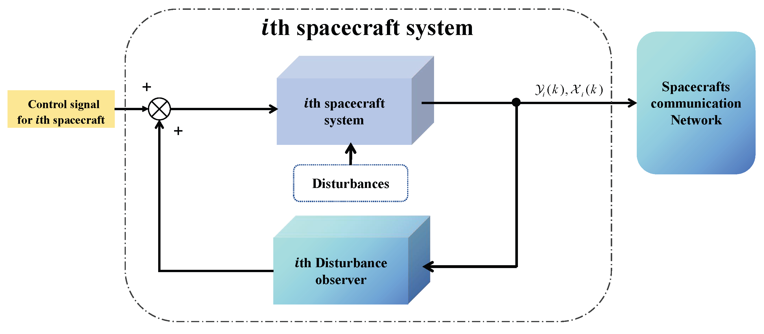
  • The proposed method combines the discrete-time fully actuated system approach with fractional-order control theory, and a sliding mode controller is developed to enable each spacecraft to track the desired attitude for the multi-spacecraft attitude system.
  • Based on the fractional-order theory, a fractional-order discrete-time disturbance observer is designed to estimate the unknown disturbances, and the observer can complete the estimation of the disturbances.
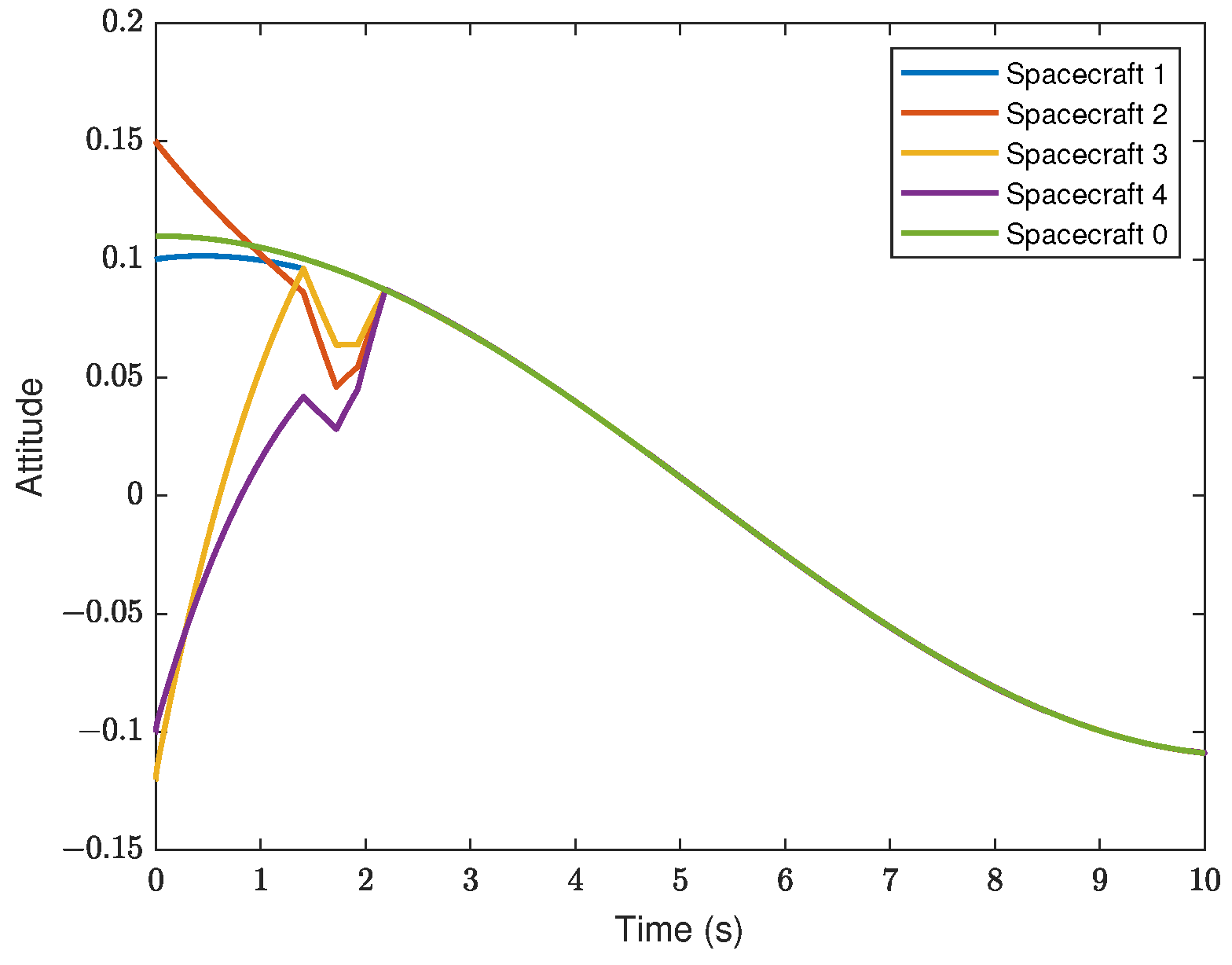
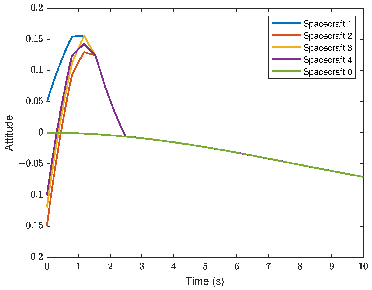
  • Based on the Lyapunov theory and simulations, the boundedness of the observer estimation error and the attitude consensus of the multi-spacecraft system are proven.
The structure of the paper is as follows: In Section 2 are the problem statement and preliminaries. The discrete-time disturbance observer based on fractional-order theory is designed in Section 3. In Section 4, a discrete-time fractional-order sliding mode controller is designed based on the fully actuated system approach, and the simulation results are demonstrated in Section 5. The Conclusions are summarized in Section 6.

2. Problem Statement and Preliminaries

Considering N spacecraft with disturbances, their simplified continuous-time attitude systems are governed by [33]
O ¯ i ( σ i ) σ ¨ i + K ¯ i ( σ i , σ ˙ i ) σ ˙ i = J T ( σ i ) ( u i + d i ) O ¯ i ( σ i ) = J T ( σ i ) M i J 1 ( σ i ) K ¯ i ( σ i , σ ˙ i ) = J T ( σ i ) M i J 1 ( σ i ) J ˙ ( σ i ) J 1 ( σ i ) J T ( σ i ) ( M i J 1 ( σ i ) σ ˙ i ) × J 1 ( σ i )
where i = 1 , 2 , 3 , , N , σ i = [ σ i 1 , σ i 2 , σ i 3 ] T represents the attitude based on modified Rodrigues parameters of the ith spacecraft, ( · ) × denotes the skew-symmetric matrix of a vector, J ( σ i ) = 1 4 1 σ i T σ i I 3 + 1 2 σ i × + 1 2 σ i σ i T 3 × 3 , M i 3 × 3 is the known mass matrix, u i is the control input, and d i is the external disturbance.
To depict the communication topology of multi-spacecraft system, Lu [34] introduced the fundamental principles and notations from graph theory. Considering a multi-spacecraft attitude formation system consisting of N spacecraft, its communication topology can be illustrated by an N-order undirected weighted graph G c = V , E , A . Then, each spacecraft denotes a node in the diagram, V = 1 , 2 , 3 , , N describes the set of spacecraft, E V × V represents the set of edges, ( i , j ) E indicates that the node i can obtain the status information of the node j. For the case G c is an undirected graph, ( j , i ) E holds if ( i , j ) E . The neighbor set of node i is described as Ω i = j V : ( i , j ) E . The adjacency matrix is defined as A = a i j , where a i j is the connection weight. If j Ω i , then a i j = 1 , otherwise a i j = 0 . The degree matrix is expressed as D = diag { D 1 , D 2 , , D N } , where D i = j Ω i a i j . Then, the Laplacian matrix L is defined as L = D A . The multi-agent system has a virtual leader, which is labeled as 0. Let B = b i , and b i is the connection weight between the ith spacecraft and the leader.
To study the discrete-time sliding mode control, the continuous-time system (1) is transformed into an approximative discrete-time system through the Euler approximation, which is proposed in [35]. The transformed discrete-time system can be written as
Y i ( k + 1 ) = Y i ( k ) + T 0 X i ( k ) X i ( k + 1 ) = X i ( k ) + T 0 ( Γ i X i ( k ) + G i u i ( k ) + d i ( k ) )
where Y i ( k ) = [ σ i 1 ( k ) , σ i 2 ( k ) , σ i 3 ( k ) ] T and X i ( k ) = [ σ ˙ i 1 ( k ) , σ ˙ i 1 ( k ) , σ ˙ i 3 ( k ) ] T , T 0 denotes the discrete sample time, Γ i = O ¯ i 1 ( Y i ( k ) ) K ¯ i ( Y i ( k ) , X i ( k ) ) 3 × 3 and G i = O ¯ i 1 ( Y i ( k ) ) J T ( Y i ( k ) ) 3 × 3 , d i ( k ) = G i d i ( k ) + Ξ i is the composite disturbance, and Ξ i is the discretization error.
Remark 1.
According to [36,37], we can know that the rigid-body spacecraft satisfies the local Lipschitz condition. So, it can be inferred that Ξ d e from [19], where d e is a bounded constant. In this condition, the discretization error Ξ can be considered as the disturbance.
In this paper, a discrete-time fractional-order sliding mode control method combined with a disturbance observer is proposed for the spacecraft system (1). The control objective is to design a discrete-time fractional-order sliding mode controller such that all followers can track the desired attitude signal Y 0 ( k ) within a bounded range under the disturbance, where the desired signal Y 0 ( k ) is a known function vector. Figure 1 and Figure 2 show the control system block diagram.
To facilitate the design of the control method, the following definitions, lemmas, and assumptions are introduced in this paper:
Definition 1
([26]). The discrete-time fractional-order Grünwald–Letnikow difference operator γ with zero initial time for the function f ( k ) given as follows:
γ f ( k ) = j = 0 k ( 1 ) j γ j f ( k j )
where the fractional order γ denotes the set of positive real numbers with 0 < γ 1 and the binomial coefficient γ j can be written as
γ j = 1 j = 0 γ ( γ 1 ) ( γ j + 1 ) j ! j > 0
Definition 2
([38]). The fractional sum of the γ order is defined by
γ f ( k ) = j = 0 k γ k j f ( j )
where the binomial coefficient γ k j can be written as
γ k j = 1 k j = 0 γ ( γ + 1 ) ( γ + k j 1 ) ( k j ) ! k j > 0
Definition 3
([15]). Considering the discrete-time model as follows:
x 1 k + 1 = f 1 x n k , u k x 2 k + 1 = f 2 x 1 k , x n k , u k x 3 k + 1 = f 3 x 1 2 k , x n k , u k x n 1 k + 1 = f n 1 x 1 n 1 k , x n k , u k x n k + 1 = f n x 1 n k + x 1 n k u k ,
where x i , i = 1 , 2 , n are system state vectors, u is a system control vector, f i ( · ) are a series of vector functions, and ( · ) is a nonlinear matrix function.
If det ( x 1 n ( k ) ) 0 , then the system (7) satisfies the fully actuated condition.
Lemma 1
([38]). For the positive real numbers γ 0 and γ 1 , we have
γ 0 γ 1 f ( k ) = γ 0 γ 1 f ( k )
Specifically, one has that 0 f ( k ) = f ( k ) .
Lemma 2
([31]). For the bounded vector ε ( k ) and 0 < γ < 1 , γ ε ( k ) is also bounded.
Assumption 1
([31]). The unknown disturbance d i ( k ) is bounded. Therefore, Δ d i ( k ) is bounded and Δ d i ( k ) = d i ( k + 1 ) d i ( k ) = T 0 ϖ i ( k ) , ϖ i ( k ) is an unknown bounded variable.
Assumption 2.
The discrete-time form of the trajectory satisfies Y 0 ( k + 1 ) = Y 0 ( k ) + T 0 X 0 ( k ) and X 0 ( k + 1 ) = X 0 ( k ) + T 0 α 0 ( k ) . α 0 ( k ) is a known bounded signal vector.
Assumption 3.
The multi-spacecraft communication topology is a connected undirected graph.

3. Discrete-Time Disturbance Observer Design

In this part, considering that the disturbance will affect the control performance of the spacecraft, it is necessary to design the corresponding disturbance observer to mitigate the impact of the disturbance.
For the discrete-time attitude system (2), we design the disturbance observer based on the fractional-order theory in the following form:
N i ( k ) = X i ( k ) X ^ i ( k ) λ γ 1 1 ( X i ( k 1 ) X ^ i ( k 1 ) ) X ^ i ( k + 1 ) = X ^ i ( k ) + T 0 ( Γ i X i ( k ) + G i u i ( k ) + d ^ i ( k ) ) λ γ 1 ( X i ( k ) X ^ i ( k ) ) d ^ i ( k ) = KN i ( k )
where N i k is the ith observer auxiliary vector, d ^ i ( k ) represents the estimated value of the disturbance of the ith observer, γ 1 is the fractional-order parameter, λ = diag [ λ 1 , λ 2 , λ 3 ] and K = diag [ K 1 , K 2 , K 3 ] are the designed positive diagonal matrices.
Theorem 1.
If the designed diagonal matrices λ, K , and discrete sample time T 0 makes [ 1 ( 1 K i T 0 ) 2 λ i T 0 2 ] > 0 and 1 K i T 0 > 0 , then the discrete-time disturbance observer can complete the estimation of the disturbance d i ( k ) .
Proof. 
We define d ˜ i ( k + 1 ) = d ( k + 1 ) d ^ i ( k + 1 ) and Δ d ˜ i ( k + 1 ) = d ˜ i ( k + 1 ) d ˜ i ( k ) . According to (9) and Assumption 1, we have
Δ d ˜ i ( k + 1 ) = d i ( k + 1 ) d i ( k ) ( d ^ i ( k + 1 ) d ^ i ( k ) ) = T 0 ϖ ( k ) K ( N i k + 1 N i k )
Substituting (9) into (10), and according to Lemma 1, we can obtain that
N i ( k + 1 ) N i ( k ) = X i ( k + 1 ) X i ( k ) X ^ i ( k + 1 ) X ^ i ( k ) λ γ 1 1 ( X i ( k ) X ^ i ( k ) ) + λ γ 1 1 ( X i ( k 1 ) X ^ i ( k 1 ) ) = T 0 d ˜ i ( k ) + λ γ 1 ( X i ( k ) X ^ i ( k ) ) λ γ 1 1 ( X i ( k ) X ^ i ( k ) ) + λ γ 1 1 ( X i ( k 1 ) X ^ i ( k 1 ) ) = T 0 d ˜ i ( k ) + λ γ 1 ( X i ( k ) X ^ i ( k ) ) λ γ 1 1 ( X i ( k ) X i ( k 1 ) ) ( X ^ i ( k ) X ^ i ( k 1 ) ) = T 0 d ˜ i ( k ) + λ γ 1 ( X i ( k ) X ^ i ( k ) ) λ γ 1 1 1 X i ( k ) 1 X ^ i ( k ) = T 0 d ˜ i ( k )
Then, it can be deduced that
Δ d ˜ i ( k + 1 ) = T 0 ϖ i ( k ) T 0 K d ˜ i ( k )
Choosing the Lyapunov function as:
V o ( k ) = d ˜ i T ( k ) O ˜ d ˜ i ( k )
where O ˜ is a positive diagonal matrix.
From (12), it can be deduced that
V o ( k + 1 ) = d ˜ i T ( k + 1 ) O ˜ d ˜ i ( k + 1 ) = n = 1 3 o ˜ n ( T 0 ϖ i , n ( k ) + ( 1 K n T 0 ) d ˜ i , n ( k ) ) 2 = n = 1 3 o ˜ n [ T 0 2 ϖ i , n 2 ( k ) + ( 1 K n T 0 ) 2 d ˜ i , n 2 ( k ) + 2 ( 1 K n T 0 ) T 0 ϖ i , n ( k ) d ˜ i , n ( k ) ]
where o ˜ n represents the nth element of O ˜ , d ˜ i , n ( k ) is the nth element of d ˜ i ( k ) , and ϖ i , n ( k ) is the nth element of ϖ i ( k ) .
Defining Δ V o ( k ) = V o ( k + 1 ) V o ( k ) , we can know
Δ V o ( k ) = n = 1 3 o ˜ n [ T 0 2 ϖ i , n ( k ) + ( ( 1 K n T 0 ) 2 1 ) d ˜ i , n 2 ( k ) + 2 ( 1 K n T 0 ) T 0 ϖ i , n ( k ) d ˜ i , n ( k ) ) ]
According to Young’s inequality, it can be inferred that
2 ϖ i , n ( k ) d ˜ i , n ( k ) 2 ( 1 K n T 0 ) λ n ϖ i , n 2 ( k ) + λ n 2 ( 1 K n T 0 ) d ˜ i , n 2 ( k )
Thus, the following inequality can be drawn
Δ V o ( k ) n = 1 3 o ˜ n [ T 0 2 ϖ i , n 2 ( k ) + ( ( 1 K n T 0 ) 2 1 + λ n T 0 2 ) d ˜ i , n 2 ( k ) + 2 ( 1 K n T 0 ) 2 T 0 λ n ϖ i , n 2 ( k ) ) ] n = 1 3 o ˜ n C n d ˜ i , n 2 ( k ) + σ C min V o ( k ) + σ
where C min = min [ C n = ( 1 ( 1 K n T 0 ) 2 λ n T 0 2 ) , n = 1 , 2 , 3 ] > 0 , n = 1 3 o ˜ n ( T 0 2 + 2 ( 1 K n T 0 ) 2 T 0 λ n ϖ n 2 ( k ) ) σ , and σ is a positive bounded constant.
If the above conditions are satisfied, we can conclude that d ˜ i ( k ) is bounded and the discrete-time disturbance observer can estimate the disturbance d i ( k ) . □

4. Fractional-Order Sliding Mode Controller Based on the Fully Actuated System Approach

To complete the control goal, we design the fractional-order sliding mode controller based on the fully actuated system approach in this section.

4.1. Fully Actuated System Transition

We define the multi-spacecraft attitude system formation error and the attitude difference error for the ith spacecraft in the following form:
e y i ( k ) = j = 1 n a i j Y i ( k ) Y j ( k ) + b i Y i ( k ) Y 0 ( k ) e x i ( k ) = j = 1 n a i j X i ( k ) X j ( k ) + b i ( X i ( k ) X 0 ( k ) )
Then, we define e y ( k ) = [ e y 1 T ( k ) , e y 2 T ( k ) , , e y N T ( k ) ] T and e x ( k ) = [ e x 1 T ( k ) , e x 2 T ( k ) , , e x N T ( k ) ] T . Thus, the system (18) can be rewritten as follows:
e y ( k ) = ( L + B ) I 3 Y ¯ ( k ) b N × 1 Y 0 ( k ) e x ( k ) = ( L + B ) I 3 X ¯ ( k ) b N × 1 X 0 ( k )
where Y ¯ ( k ) = Y 1 T ( k ) , Y 2 T ( k ) , , Y N T ( k ) T and X ¯ ( k ) = X 1 T ( k ) , X 2 T ( k ) , , X N T ( k ) T , b N × 1 = b 1 , b 2 , , b N T .
Combining the ith spacecraft attitude system (2) and (19), we have,
e y ( k + 1 ) = e y ( k ) + T 0 e x ( k ) e x ( k + 1 ) = e x ( k ) + ( L + B ) I 3 T 0 ( Γ ¯ X ¯ ( k ) ) + ( L + B ) I 3 T 0 ( G ¯ u ¯ ( k ) + d ¯ ( k ) ) T 0 b N × 1 α 0 ( k )
where Γ ¯ = diag ( Γ 1 , Γ 2 , , Γ N ) 3 N × 3 N , G ¯ = diag ( G 1 , G 2 , , G N ) 3 N × 3 N , u ¯ ( k ) = [ u 1 T ( k ) , u 2 T ( k ) , , u N T ( k ) ] T 3 N × 1 and d ¯ ( k ) = [ d 1 T ( k ) , d 2 T ( k ) , , d N T ( k ) ] T 3 N × 1 .
For facilitating subsequent controller design, we define H = ( L + B ) I 3 . Thus, H is a positive definite matrix through Assumption 3. Substituting (19) into (20), it can be deduced that
e y ( k + 1 ) = e y ( k ) + T 0 e x ( k ) e x ( k + 1 ) = ( I 3 N + T 0 H Γ ¯ H 1 ) e x ( k ) + T 0 H ( G ¯ u ¯ ( k ) + d ¯ ( k ) ) T 0 b N × 1 α 0 ( k ) + T 0 H Γ ¯ H 1 ( b N × 1 X 0 ( k ) )
Because rank ( T 0 H G ¯ ) = 3 N , the multi-spacecraft formation attitude error system (21) is a fully actuated system from Definition 3. To simplify the subsequent expressions, the system is reformulated as
e y ( k + 1 ) = f 1 ( e y ( k ) ) + g 1 e x ( k ) , e x ( k + 1 ) = f 2 ( e y ( k ) , e x ( k ) ) + g 2 ( e y ( k ) , e x ( k ) ) u ¯ ( k ) + T 0 H d ¯ ( k ) + Θ
where f 1 ( e y ( k ) ) = e y ( k ) , g 1 = T 0 , f 2 ( e y ( k ) , e x ( k ) ) = ( I 3 N + T 0 H Γ ¯ H 1 ) e x ( k ) , g 2 ( e y ( k ) , e x ( k ) ) = T 0 H G ¯ , Θ = T 0 b N × 1 α 0 ( k ) + T 0 H Γ ¯ H 1 ( b N × 1 X 0 ( k ) ) .
Then, according to the discrete time fully actuated system approach, we define the coordinate transformation as
Z 1 ( k ) = e y ( k ) Z 2 ( k ) = f 1 ( e y ( k ) ) + g 1 e x ( k )
Then, it can be deduced that
Z 2 ( k + 1 ) = e y ( k + 1 ) + g 1 e x ( k + 1 ) = e y ( k + 1 ) + g 1 f 2 ( e y ( k ) , e x ( k ) ) + g 1 g 2 ( e y ( k ) , e x ( k ) ) u ¯ ( k ) + g 1 T 0 H d ¯ ( k ) + g 1 Θ
From (23), we can obtain that
e y ( k ) = Z 1 ( k ) e x ( k ) = g 1 1 Z 2 ( k ) Z 1 ( k )
Consequently, the original system (21) can be rewritten by Z 1 ( k ) and Z 2 ( k ) in the following step backward fully actuated form:
Z 1 ( k + 1 ) = Z 2 ( k ) Z 2 ( k + 1 ) = Z 2 ( k ) + g 1 f 2 ( Z 1 ( k ) , Z 2 ( k ) ) + g 1 Θ + g 1 g 2 ( Z 1 ( k ) , Z 2 ( k ) ) u ¯ ( k ) + g 1 T 0 H d ¯ ( k )
where f 2 ( Z 1 ( k ) , Z 2 ( k ) ) = f 2 ( e y ( k ) , e x ( k ) ) and g 2 ( Z 1 ( k ) , Z 2 ( k ) ) = g 2 ( e y ( k ) , e x ( k ) ) .
By using the discrete-time fully actuated system approach [15], we design the controller in the following form:
u ¯ ( k ) = ( g 1 g 2 ( Z 1 ( k ) , Z 2 ( k ) ) ) 1 ( Z 2 ( k ) q ( k ) +   g 1 f 2 ( Z 1 ( k ) , Z 2 ( k ) ) ) q ( k ) = Ψ 1 Z 1 ( k ) + Ψ 2 Z 2 ( k ) + l ( k ) g 1 Θ
where l ( k ) is the designed sliding mode controller in the subsequent part, Ψ 1 and Ψ 2 are the selected matrices through the fully actuated system approach.
Through the discrete-time fully actuated system approach, the discrete-time attitude formation system (21) can convert the following system:
Z 1 ( k + 1 ) = Z 2 ( k ) Z 2 ( k + 1 ) = Ψ 1 Z 1 ( k ) + Ψ 2 Z 2 ( k ) + l ( k ) + g 1 T 0 H d ¯ ( k )
Remark 2.
Ψ 1 and Ψ 2 3 N × 3 N are constant matrices, and their design criteria are in the following form: Firstly, choose a Hurwitz matrix Ω ¯ 6 N × 6 N and a matrix Φ 3 N × 6 N . Then, we define V ( Ω ¯ , Φ ) = Ω ¯ Ω ¯ Φ 6 N × 6 N . It can obtain that Ψ 1 , Ψ 2 = Φ Ω ¯ 2 V 1 ( Ω ¯ , Φ ) according to the fully actuated system approach [39].
Remark 3.
The discrete-time fully actuated system approach allows us to configure the matrices [ Ψ 1 , Ψ 2 ] in the controller (27), which guarantees that the transformed system possesses the desired closed-loop properties. This approach enables the controller designed in the subsequent part to have improved flexibility and robustness. Therefore, l ( k ) will be constructed on the basis of the transformed system.

4.2. Fractional-Order Sliding Mode Controller Design and Stability Analysis

In this subsection, a discrete-time fractional-order sliding mode controller will be adopted to ensure that the attitude formation error can be bounded.
Choose the fractional-order sliding mode as:
S ( k ) = Q 1 γ 2 1 Z 1 ( k ) + Z 2 ( k )
where Q 1 3 N × 3 N is a designed positive diagonal matrix, abd γ 2 is the fractional-order parameter.
From (28) and (29), we design the sliding mode controller in the following form:
l ( k ) = Q 1 γ 2 Z 2 ( k ) Ψ 1 Z 1 ( k ) ( Ψ 2 I 3 N ) Z 2 ( k ) g 1 T 0 H d ^ ¯ ( k ) q 1 T 0 S ( k ) q 2 T 0 sgn [ S ( k ) ]
where d ^ ¯ ( k ) = [ d ^ 1 T ( k ) , d ^ 2 T ( k ) , , d ^ N T ( k ) ] T , q 1 3 N × 3 N and q 2 3 N × 3 N are the positive diagonal matrices, and sgn [ · ] is the sign function.
Theorem 2.
For the spacecraft attitude error formation system (28), if I 3 N q 1 T q 2 and 2 I 3 N q 1 T q 1 are positive definite matrices, by the fully actuated approach controller (27), the discrete-time fractional-order sliding mode controller (30), and the observer (9). The formation attitude error can be bounded, and every spacecraft can track the virtual leader attitude signal.
Proof. 
According to Lemma 1 and (29), we can know
S ( k + 1 ) S ( k ) = Q 1 γ 2 1 Z 1 ( k + 1 ) Z 1 ( k ) + Z 2 ( k + 1 ) Z 2 ( k ) = Q 1 γ 2 1 1 Z 1 ( k + 1 ) + ( Z 2 ( k + 1 ) Z 2 ( k ) ) = Q 1 γ 2 Z 1 ( k + 1 ) + ( Z 2 ( k + 1 ) Z 2 ( k ) )
From (28) and (30), we can obtain that
S ( k + 1 ) S ( k ) = Q 1 γ 2 Z 2 ( k ) + [ Ψ 1 Z 1 ( k ) + Ψ 2 I 3 N Z 2 ( k ) + l ( k ) + g 1 T 0 H d ¯ ( k ) ] = Q 1 γ 2 Z 2 ( k ) + [ Q 1 γ 2 Z 2 ( k ) + g 1 T 0 H d ˜ ¯ ( k ) q 1 T 0 S ( k )   q 2 T 0 sgn [ S ( k ) ] ] = g 1 T 0 H d ˜ ¯ ( k ) q 1 T 0 S ( k ) q 2 T 0 sgn [ S ( k ) ]
where d ˜ ¯ ( k ) = [ d ˜ 1 T ( k ) , d ˜ 2 T ( k ) , , d ˜ N T ( k ) ] T .
Then, we choose the Lyapunov function in the following form:
V s ( k ) = 1 T 0 2 S T ( k ) S ( k )
Thus, the first difference is calculated as
Δ V s ( k ) = 1 T 0 2 S T ( k + 1 ) S ( k + 1 ) 1 T 0 2 S T ( k ) S ( k ) = 1 T 0 2 S ( k + 1 ) + S ( k ) T S ( k + 1 ) S ( k )
Substituting (32) into (34), we have
Δ V s ( k ) = g 1 H d ˜ ¯ ( k ) + 2 I 3 N q 1 S ( k ) q 2 sgn [ S ( k ) ] T g 1 H d ˜ ¯ ( k ) q 1 S ( k ) q 2 sgn [ S ( k ) ] =   S T ( k ) 2 I 3 N q 1 T q 1 S ( k ) + g 1 2 d ˜ ¯ T ( k ) H T H d ˜ ¯ ( k ) +   2 g 1 S T ( k ) I 3 N q 1 T H d ˜ ¯ ( k ) 2 S T ( k ) I 3 N q 1 T q 2 sgn [ S ( k ) ]   2 g 1 d ˜ ¯ T ( k ) H T q 2 sgn [ S ( k ) ] + sgn [ S ( k ) ] T q 2 T q 2 sgn [ S ( k ) ]
Because ( I 3 N q 1 ) T q 2 and q 2 are known positive definite matrices, we can easily derive the following inequalities based on the properties of the sign function.
2 S T ( k ) I 3 N q 1 T q 2 sgn [ S ( k ) ] 0
sgn [ S ( k ) ] T q 2 T q 2 sgn [ S ( k ) ] τ 1
where τ 1 is a positive bounded constant.
Additionally, according to Theorem 1, we know
2 g 1 d ˜ ¯ T ( k ) H T q 2 sgn [ S ( k ) ] ξ 1
where ξ 1 is a positive bounded constant.
Moreover, from Young’s inequality, it can be deduced that
2 g 1 S T ( k ) I 3 N q 1 T H d ˜ ¯ ( k ) 2 g 1 λ max ( I 3 N q 1 T H ) | | S T ( k ) | | 2 | | d ˜ ( k ) | | 2 g 1 λ max I 3 N q 1 T H ) [ λ min 0.5 2 I 3 N q 1 T q 1 g 1 λ max ( I 3 N q 1 T H ) S T ( k ) S ( k ) + g 1 λ max ( I 3 N q 1 T H ) λ min 0.5 2 I 3 N q 1 T q 1 d ˜ ¯ T ( k ) d ˜ ¯ ( k ) ]
where λ min ( · ) denotes the minimum eigenvalue of the matrix, λ max ( · ) denotes the maximum eigenvalue of the matrix, | | · | | 2 denotes the 2-norm.
Therefore, (35) can be written as:
Δ V s ( k ) S T ( k ) 2 I 3 N q 1 T q 1 S ( k ) + λ min 0.5 2 I 3 N q 1 T q 1 S T ( k ) S ( k ) + τ 1 + ξ 1 + g 1 2 λ max 2 ( I 3 N q 1 T H ) λ min 0.5 2 I 3 N q 1 T q 1 d ˜ ¯ T ( k ) d ˜ ¯ ( k ) + g 1 2 d ˜ ¯ T ( k ) H T H d ˜ ¯ ( k ) λ min 0.5 2 I 3 N q 1 T q 1 S T ( k ) S ( k ) + g 1 2 λ max 2 ( I 3 N q 1 T H ) λ min 0.5 2 I 3 N q 1 T q 1 d ˜ ¯ T ( k ) d ˜ ¯ ( k ) + τ 1 + ξ 1 + g 1 2 d ˜ ¯ T ( k ) H T H d ˜ ¯ ( k ) κ 1 V s ( k ) + κ 2
where κ 1 = T 0 2 λ min 0.5 2 I 3 N q 1 T q 1 > 0 , κ 2 = τ 1 + ξ 1 + g 1 2 λ max 2 ( I 3 N q 1 T H ) λ min 0.5 2 I 3 N q 1 T q 1 d ˜ ¯ T ( k ) d ˜ ¯ ( k ) + g 1 2 d ˜ ¯ T ( k ) H T H d ˜ ¯ ( k ) , and κ 2 is a positive bounded value.
Above all, we can obtain that the formation attitude error can be bounded to zero. Additionally, every spacecraft can track the virtual leader’s attitude. □

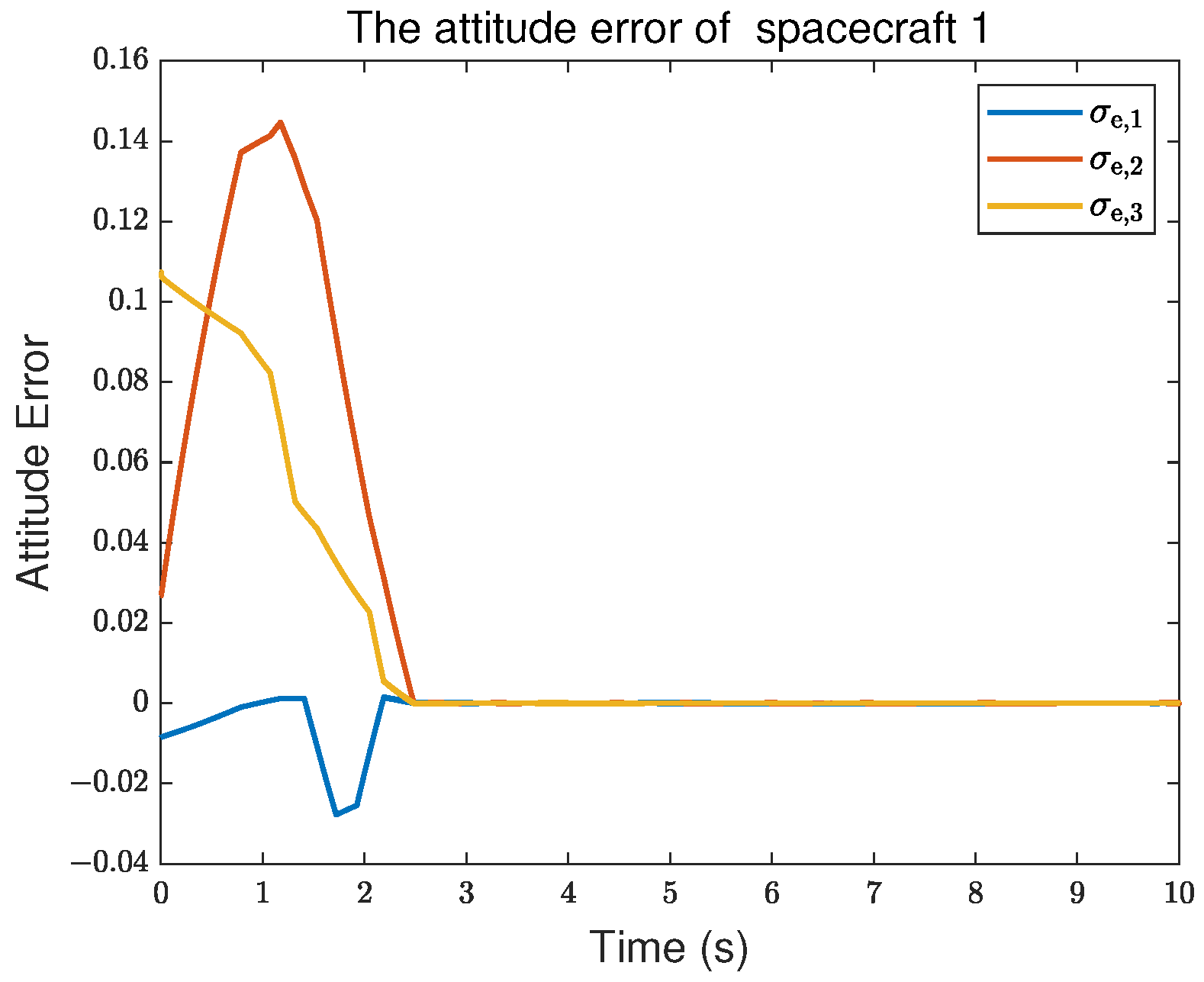
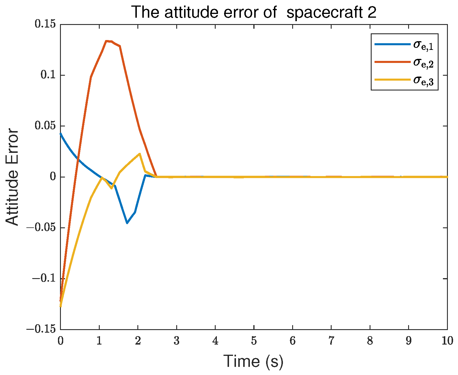
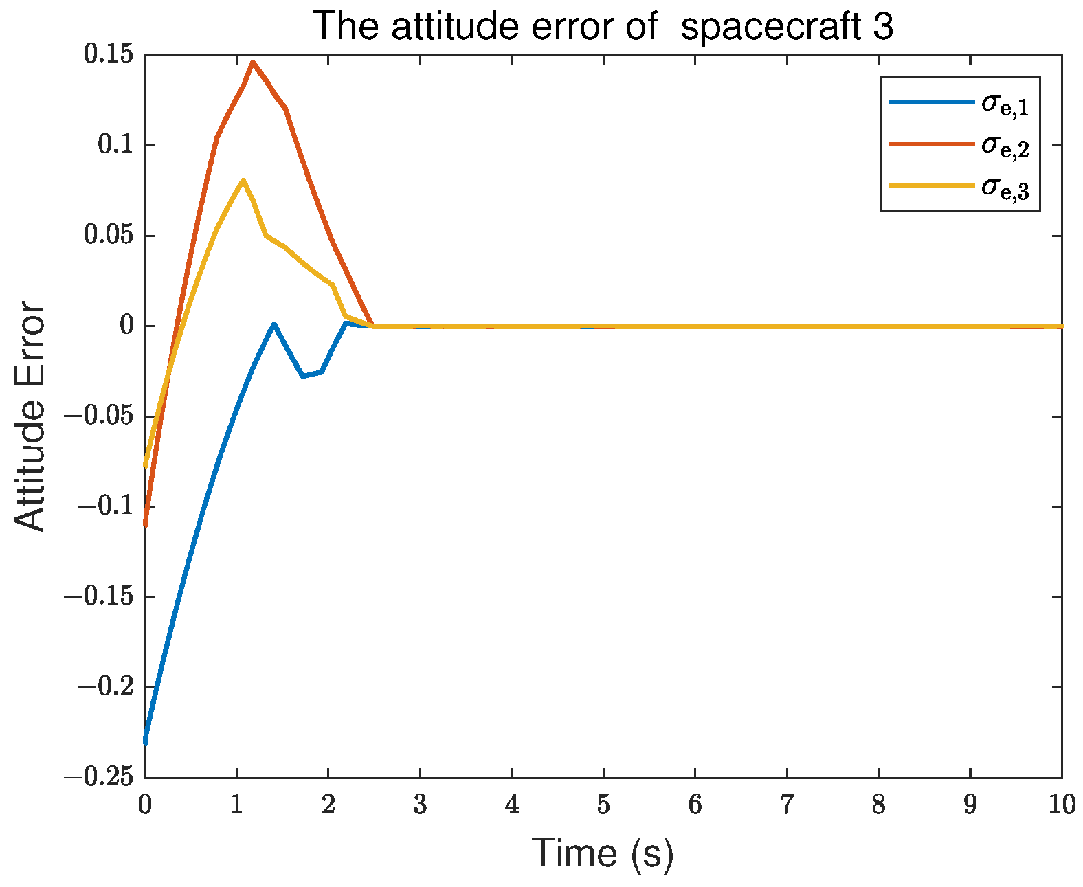
5. Simulation Results

To verify the effectiveness of the designed observer and controller, there are some simulation results. Set the parameters of M i as
M i = 20 1.2 0.9 1.2 17 1.4 0.9 1.4 15 kg · m 2
In this simulation, the communication topology of the multi-spacecraft system is presented in Figure 3.
The initial states of every spacecraft are chosen as
Y 1 ( 0 ) = 0.1 , 0.05 , 0.1 T X 1 ( 0 ) = 0.004 , 0.003 , 0.005 T Y 2 ( 0 ) = 0.15 , 0.15 , 0.1 T X 2 ( 0 ) = 0.004 , 0.005 , 0.007 T Y 3 ( 0 ) = 0.12 , 0.12 , 0.05 T X 3 ( 0 ) = 0.005 , 0.005 , 0.005 T Y 4 ( 0 ) = 0.1 , 0.1 , 0.1 T X 4 ( 0 ) = 0.003 , 0.009 , 0.006 T
The discrete-time virtual leader signal is derived from the following associated signal:
Y 0 ( t ) = 0.11 cos ( 0.3 t ) 0.05 cos ( 0.2 t ) 0.05 0.05 sin ( 0.2 t )
The discrete-time disturbance d ( k ) is derived from the following associated disturbance:
d ( t ) = 2 1 sin ( 0.3 t ) 4 cos ( 0.1 t ) 5 sin ( 0.25 t ) 1 cos ( 0.4 t ) 1 × 10 3   N · m
Then, the parameters of the observer are chosen as λ = 0.01 I 3 , K = diag [ 20 , 16 , 16 ] , γ 1 = 0.5 and γ 2 = 0.55 , the parameters of the controller are chosen as ψ 1 = 0.351 I 12 , ψ 2 = 0.165 I 12 , Q 1 = 0.005 I 12 , q 1 = 0.1 I 12 , and q 2 = 0.1 I 12 . Additionally, the discrete sample time is T 0 = 0.001   s .
Based on the parameters above, Figure 4, Figure 5, Figure 6 and Figure 7 show the simulation results. In Figure 4, the discrete-time disturbance observer enables accurate estimation of disturbance d ( k ) while the estimation errors are bounded. Moreover, Figure 5, Figure 6 and Figure 7 present the attitude tracking results for the virtual leader and the followers. As shown in Figure 8, Figure 9, Figure 10 and Figure 11, the attitude error between each spacecraft and the virtual leader demonstrates that the proposed controller enables all spacecraft not only to achieve but also to maintain attitude consensus with the virtual leader (where σ e , i denotes the attitude error between the spacecraft and spacecraft 0 for the ith dimension). The simulation results validate that the discrete-time fractional-order sliding mode control method proposed in this paper can effectively achieve cooperative control for a multi-spacecraft system.
To assess the proposed controller, there are some simulations to compare the control performance with other controllers. As shown in Figure 12 and Table 1, under identical conditions, the fractional-order controller proposed in this paper exhibits faster setting time and reduced overshoot when compared to the integer-order controller. Furthermore, it shows improved attitude square error over the simulation period, indicating a clear advantage in fractional-order control. Compared with other fractional-order control method, the proposed approach still maintains a favorable setting time and high control accuracy. Nevertheless, it shows relatively poorer performance in the square error and overshoot.
To assess the controller parameter tuning sensitivity and applicability under various communication topologies, some simulations have been added. Figure 13 shows the new communication topology, and the parameters are set as λ = 0.005 I 3 , K = diag [ 50 , 36 , 36 ] , γ 1 = 0.55 , γ 2 = 0.35 , Q 1 = 0.002 I 12 , q 1 = 0.15 I 12 , and q 2 = 0.05 I 12 . In this situation, the attitude tracking of every spacecraft is shown in Figure 14. From Figure 14, we see that the proposed controller still enables each spacecraft to achieve attitude consensus. Moreover, it demonstrates applicability under various communication topologies and exhibits relatively low tuning sensitivity with respect to the relevant parameters that satisfy the design conditions.

6. Conclusions

In this paper, a discrete-time fractional-order sliding mode controller based on the fully actuated system approach has been proposed for the multi-spacecraft attitude tracking problem. This controller can enable every spacecraft to track the virtual leader’s attitude. To compensate for the disturbances, a discrete-time observer based on the fractional-order theory has been designed. This observer can ensure estimation errors are bounded. Finally, simulations are provided to show that the designed controller in this paper can make every spacecraft track the virtual leader’s attitude quickly under disturbances. Future work will involve extending the controller to a multi-spacecraft system with uncertain inertia matrices and communication delays, as well as further developing the optimization-based framework to enhance control performance.

Author Contributions

Conceptualization, Y.C. and S.S.; methodology, Y.C. and S.S.; software, Y.C. and S.S.; validation, Y.C. and S.S.; formal analysis, Y.C. and S.S.; writing—original draft preparation, Y.C.; writing—review and editing, Y.C. and S.S.; supervision, S.S.; funding acquisition, S.S. All authors have read and agreed to the published version of the manuscript.

Funding

The authors declare that financial support was received for the research, authorship, and/or publication of this article. This work is supported by the National Natural Science Foundation of China under Grant 62188101 and Funded by National Laboratory of Space Intelligent Control under Grant HTKJ2023KL502002.

Data Availability Statement

Data are contained within the article.

Conflicts of Interest

The authors declare no conflicts of interest.

References

  1. Sui, W.; Duan, G.; Hou, M.; Zhang, M. Distributed fixed-time attitude coordinated tracking for multiple rigid spacecraft via a novel integral sliding mode approach. J. Frankl. Inst. 2020, 357, 9399–9422. [Google Scholar] [CrossRef]
  2. Cui, B.; Zhang, L.; Xia, Y.; Zhang, J. Continuous distributed fixed-time attitude controller design for multiple spacecraft systems with a directed graph. IEEE Trans. Circuits Syst. II Express Briefs 2022, 69, 4478–4482. [Google Scholar] [CrossRef]
  3. Xu, C.; Wu, B.; Zhang, Y. Distributed prescribed-time attitude cooperative control for multiple spacecraft. Aerosp. Sci. Technol. 2021, 113, 106699. [Google Scholar] [CrossRef]
  4. Kang, Z.; Shen, Q.; Wu, S.; Damaren, C.J. Saturated attitude control of multispacecraft systems on SO(3) subject to mixed attitude constraints with arbitrary initial attitude. IEEE Trans. Aerosp. Electron. Syst. 2023, 59, 5158–5173. [Google Scholar]
  5. Yang, C.; Xia, Y. Interval uncertainty-oriented optimal control method for spacecraft attitude control. IEEE Trans. Aerosp. Electron. Syst. 2023, 59, 5460–5471. [Google Scholar] [CrossRef]
  6. Xie, X.; Sheng, T.; Chen, X. Dynamic event-triggered and self-triggered fault-tolerant attitude control for multiple spacecraft systems with uncertainties and input saturation. IEEE Trans. Aerosp. Electron. Syst. 2024, 60, 2922–2933. [Google Scholar] [CrossRef]
  7. Campos-Martínez, S.N.; Hernández-González, O.; Guerrero-Sánchez, M.E.; Valencia-Palomo, G.; Targui, B.; López-Estrada, F.R. Consensus Tracking Control of Multiple Unmanned Aerial Vehicles Subject to Distinct Unknown Delays. Machines 2024, 12, 337. [Google Scholar] [CrossRef]
  8. Wu, Y.; Sun, X.; Wang, T.; Wang, J. PD-like Consensus Tracking Algorithm for Discrete Multi-Agent Systems with Time-Varying Reference State Under Binary-Valued Communication. Actuators 2025, 14, 267. [Google Scholar] [CrossRef]
  9. Chang, X.; Yang, Y.; Zhang, Z.; Jiao, J.; Cheng, H.; Fu, W. Consensus-Based Formation Control for Heterogeneous Multi-Agent Systems in Complex Environments. Drones 2025, 9, 175. [Google Scholar] [CrossRef]
  10. Abidi, K.; Xu, J.X. Advanced Discrete-Time Control; Springer: Singapore, 2015. [Google Scholar]
  11. Laila, D.S.; Lovera, M.; Astolfi, A. A discrete-time observer design for spacecraft attitude determination using an orthogonality-preserving algorithm. Automatica 2011, 47, 975–980. [Google Scholar] [CrossRef]
  12. Lee, K.; Park, C.; Lee, T.; Park, S.Y. Spacecraft formation keeping via discrete-time Hamilton-Jacobi theory. In Proceedings of the AIAA Guidance, Navigation, and Control Conference, San Diego, CA, USA, 4–8 January 2016; p. 0874. [Google Scholar]
  13. Phogat, K.S.; Chatterjee, D.; Banavar, R. Discrete-time optimal attitude control of a spacecraft with momentum and control constraints. J. Guid. Control Dyn. 2018, 41, 199–211. [Google Scholar] [CrossRef]
  14. Duan, G. High-order fully actuated system approaches: Part I. Models and basic procedure. Int. J. Syst. Sci. 2021, 52, 422–435. [Google Scholar] [CrossRef]
  15. Duan, G. High-order fully actuated system approaches: Part X. Basics of discrete-time systems. Int. J. Syst. Sci. 2022, 53, 810–832. [Google Scholar] [CrossRef]
  16. Wang, X.; Duan, G. Fully actuated system approaches: Predictive elimination control for discrete-time nonlinear time-varying systems with full state constraints and time-varying delays. IEEE Trans. Circuits Syst. I Regul. Pap. 2023, 71, 383–396. [Google Scholar] [CrossRef]
  17. Yu, X.; Feng, Y.; Man, Z. Terminal sliding mode control—An overview. IEEE Open J. Ind. Electron. Soc. 2020, 2, 36–52. [Google Scholar] [CrossRef]
  18. Utkin, V.; Poznyak, A.; Orlov, Y.; Polyakov, A. Conventional and high order sliding mode control. J. Frankl. Inst. 2020, 357, 10244–10261. [Google Scholar] [CrossRef]
  19. Chen, L.; Yan, Y.; Mu, C.; Sun, C. Characteristic model-based discrete-time sliding mode control for spacecraft with variable tilt of flexible structures. IEEE/CAA J. Autom. Sin. 2016, 3, 42–50. [Google Scholar] [CrossRef]
  20. Chen, Z.; Ju, X.; Wang, Z.; Li, Q. The prescribed time sliding mode control for attitude tracking of spacecraft. Asian J. Control 2022, 24, 1650–1662. [Google Scholar] [CrossRef]
  21. Tan, J.; Zhang, K.; Li, B.; Wu, A.G. Event-triggered sliding mode control for spacecraft reorientation with multiple attitude constraints. IEEE Trans. Aerosp. Electron. Syst. 2023, 59, 6031–6043. [Google Scholar] [CrossRef]
  22. Chen, Y.; Petras, I.; Xue, D. Fractional order control-a tutorial. In Proceedings of the 2009 American Control Conference, St. Louis, MO, USA, 10–12 June 2009; pp. 1397–1411. [Google Scholar]
  23. Xue, D. Fractional-Order Control Systems: Fundamentals and Numerical Implementations; Walter de Gruyter GmbH & Co KG: Berlin, Germany, 2017; Volume 1. [Google Scholar]
  24. Tepljakov, A.; Alagoz, B.B.; Yeroglu, C.; Gonzalez, E.A.; Hosseinnia, S.H.; Petlenkov, E.; Ates, A.; Cech, M. Towards industrialization of FOPID controllers: A survey on milestones of fractional-order control and pathways for future developments. IEEE Access 2021, 9, 21016–21042. [Google Scholar] [CrossRef]
  25. Muresan, C.I.; Birs, I.; Ionescu, C.; Dulf, E.H.; De Keyser, R. A review of recent developments in autotuning methods for fractional-order controllers. Fractal Fract. 2022, 6, 37. [Google Scholar] [CrossRef]
  26. Sopasakis, P.; Sarimveis, H. Stabilising model predictive control for discrete-time fractional-order systems. Automatica 2017, 75, 24–31. [Google Scholar] [CrossRef]
  27. Sun, G.; Ma, Z.; Yu, J. Discrete-time fractional order terminal sliding mode tracking control for linear motor. IEEE Trans. Ind. Electron. 2017, 65, 3386–3394. [Google Scholar] [CrossRef]
  28. Zhang, F.; Yang, C.; Zhou, X.; Gui, W. Optimal setting and control strategy for industrial process based on discrete-time fractional-order PID. IEEE Access 2019, 7, 47747–47761. [Google Scholar] [CrossRef]
  29. Ekinci, S.; Izci, D.; Turkeri, C.; Ahmad, M.A. Spider Wasp Optimizer-Optimized Cascaded Fractional-Order Controller for Load Frequency Control in a Photovoltaic-Integrated Two-Area System. Mathematics 2024, 12, 3076. [Google Scholar] [CrossRef]
  30. Gupta, D.K.; Dei, G.; Soni, A.K.; Jha, A.V.; Appasani, B.; Bizon, N.; Srinivasulu, A.; Nsengiyumva, P. Fractional order PID controller for load frequency control in a deregulated hybrid power system using Aquila Optimization. Results Eng. 2024, 23, 102442. [Google Scholar] [CrossRef]
  31. Shao, S.; Chen, M. Robust discrete-time fractional-order control for an unmanned aerial vehicle based on disturbance observer. Int. J. Robust Nonlinear Control 2022, 32, 4665–4682. [Google Scholar] [CrossRef]
  32. Wu, F.; Liu, M.; Feng, Z.; Cao, X. Fractional-order sliding mode attitude coordinated control for spacecraft formation flying with unreliable wireless communication. IET Control Theory Appl. 2023, 17, 368–380. [Google Scholar] [CrossRef]
  33. Meng, Z.; Ren, W.; You, Z. Distributed finite-time attitude containment control for multiple rigid bodies. Automatica 2010, 46, 2092–2099. [Google Scholar] [CrossRef]
  34. Lu, M.; Liu, L. Leader-following attitude consensus of multiple rigid spacecraft systems under switching networks. IEEE Trans. Autom. Control 2019, 65, 839–845. [Google Scholar] [CrossRef]
  35. Mareels, I.M.; Penfold, H.; Evans, R.J. Controlling nonlinear time-varying systems via Euler approximations. Automatica 1992, 28, 681–696. [Google Scholar] [CrossRef]
  36. Xie, S.; Chen, Q.; He, X. Predefined-Time Approximation-Free Attitude Constraint Control of Rigid Spacecraft. IEEE Trans. Aerosp. Electron. Syst. 2023, 59, 347–358. [Google Scholar] [CrossRef]
  37. Sun, X.; Shen, Q.; Wu, S. Fuzzy Supervised Learning-Based Model-Free Adaptive Fault-Tolerant Spacecraft Attitude Control With Deferred Asymmetric Constraints. IEEE Trans. Aerosp. Electron. Syst. 2023, 59, 8884–8900. [Google Scholar] [CrossRef]
  38. Meng, W.; Liu, S.; Zeng, B.; Fang, Z. Mutual invertibility of discrete fractional summation operator and difference operator. Math. Pract. Theory 2015, 6, 261–266. [Google Scholar]
  39. Duan, G. High-order fully actuated system approaches: Part VII. Controllability, stabilisability and parametric designs. Int. J. Syst. Sci. 2021, 52, 3091–3114. [Google Scholar] [CrossRef]
Figure 1. The system of the ith spacecraft.
Fractalfract 09 00435 g001
Figure 2. The control scheme of the multi-spacecraft system.
Fractalfract 09 00435 g002
Figure 3. The communication topology.
Fractalfract 09 00435 g003
Figure 4. The observer (9) estimation of the disturbances for spacecraft 1.
Fractalfract 09 00435 g004
Figure 5. The first component of the attitude.
Fractalfract 09 00435 g005
Figure 6. The second component of the attitude.
Fractalfract 09 00435 g006
Figure 7. The third component of the attitude.
Fractalfract 09 00435 g007
Figure 8. The attitude error between spacecraft 1 and the virtual leader.
Fractalfract 09 00435 g008
Figure 9. The attitude error between spacecraft 2 and the virtual leader.
Fractalfract 09 00435 g009
Figure 10. Theattitude error between spacecraft 3 and the virtual leader.
Fractalfract 09 00435 g010
Figure 11. The attitude error between spacecraft 4 and the virtual leader.
Fractalfract 09 00435 g011
Figure 12. The attitude error under different controllers [31].
Fractalfract 09 00435 g012
Figure 13. The new communication topology.
Fractalfract 09 00435 g013
Figure 14. The attitude of every spacecraft.
Fractalfract 09 00435 g014
Table 1. Controller performance comparison.
Controller TypeMaximum OvershootSettling TimeSquare Error
Proposed controller0.14<3 s36.9631
Integer-order
sliding mode controller
0.25<5 s145.9648
Fractional-order
backstepping controller
No Overshoot<7 s12.3702
Maximum Overshoot: Maximum attitude error when overshoot exists, calculated as max | σ e , i | where i = 1 , 2 , 3 . Settling Time: Maximum settling time for i = 1 , 2 , 3 . Square Error: Sum of squared error over simulation period, calculated as k = 0 10 / T 0 σ e , l 2 ( k ) + σ e , 2 2 ( k ) + σ e , 3 2 ( k ) .
Disclaimer/Publisher’s Note: The statements, opinions and data contained in all publications are solely those of the individual author(s) and contributor(s) and not of MDPI and/or the editor(s). MDPI and/or the editor(s) disclaim responsibility for any injury to people or property resulting from any ideas, methods, instructions or products referred to in the content.

