Article

Realization of Fractional-Order Current-Mode Multifunction Filter Based on MCFOA for Low-Frequency Applications

Department of Engineering, Harran University, Sanliurfa 63290, Turkey
*
Author to whom correspondence should be addressed.
Fractal Fract. 2025, 9(6), 377; https://doi.org/10.3390/fractalfract9060377
Submission received: 25 April 2025 / Revised: 6 June 2025 / Accepted: 10 June 2025 / Published: 13 June 2025

Abstract

The present work proposes a novel fractional-order multifunction filter topology in current-mode (CM), which is designed based on the Modified Current Feedback Operational Amplifier (MCFOA). The proposed design simultaneously generates fractional-order low-pass (FO-LPF), high-pass (FO-HPF), and band-pass (FO-BPF) outputs while utilizing an optimized set of essential active and passive elements, thereby ensuring simplicity, cost efficiency, and compatibility with integrated circuits (ICs). The fractional-order feature allows precise control over the transition slope between the passband and the stopband, enhancing design flexibility. PSpice simulations validated the filter’s theoretical performance, confirming a 1 kHz cut-off frequency, making it suitable for VLF applications such as military communication and submarine navigation. Monte Carlo analyses demonstrate robustness against parameter variations, while a low THD, a wide dynamic range, and low power consumption highlight its efficiency for high-precision, low-power applications. This work offers a practical and adaptable approach to fractional-order circuit design, with significant potential in communication, control, and biomedical systems.

1. Introduction

Continuous-time analog filtering structures represent one of the most extensively applied methodologies within the field of signal analysis, as they are primarily utilized to isolate essential frequency components from the input signal or eliminate undesired ones. These filters find extensive application across a broad range of radio frequency bands, including areas such as electrocardiography (ECG), electroencephalography (EEG), sensor technologies, control systems, robotics, and automation, as well as military and submarine communication systems. In order to more effectively meet the performance requirements in such fields, analog filters have increasingly been designed using fractional calculus, resulting in fractional-order filter structures [1].
Fractional-order analysis constitutes a branch of mathematics concerned with the exploration of non-integer order integration and differentiation operators. The conventional (integer-based) calculus can be interpreted as a particular instance within the broader scope of fractional-order theory. One of the most notable aspects of fractional calculus is its ability to introduce additional degrees of freedom into system models by incorporating parameters such as the order of the derivative. This additional flexibility enables a more precise and adaptable description of system behavior, thereby enhancing modeling and control capabilities. As a result, fractional-order modeling has evolved from a purely theoretical mathematical concept into a powerful and rapidly expanding tool in various applied and interdisciplinary fields, including engineering, physics, agriculture, wireless power transfer, biomedical systems, control theory, and signal processing. Equation (1) illustrates the fractional-order derivative as defined by the Riemann–Liouville formulation [2].
d α d t α f ( t ) D t α f ( t ) = 1 Γ ( n α ) d d t n 0 t ( t τ ) n α 1 f ( τ ) d τ
Here, n represents a positive whole number, while α ( n 1 α < n ) corresponds to a real valued parameter, and Γ ( ) refers to the gamma function. Assuming zero initial conditions, the Laplace-domain representation of the expression defined in Equation (1) is given in Equation (2).
L D t α f ( t ) = s α F ( s )
Consequently, a generalized fractional-order component can be introduced, characterized by an impedance that varies with s α . As an example, the pseudo-capacitor exhibits an impedance defined by Equation (3).
Z C α ( s ) = 1 / s α C
In Equation (3), C denotes the fractional-order capacitance, whose dimensional unit is expressed as F / s 1 α .
In recent years, filters based on fractional-order calculus have attracted considerable attention owing to their distinctive spectral characteristics, which set them apart from conventional filter structures. In contrast to classical approaches, the spectral behavior of these filters is influenced not only by the values of the circuit elements but also by the fractional differentiation order involved [3]. For example, in conventional low-pass (LP) and high-pass (HP) filter configurations, the roll-off rates in the stopband are typically expressed as 20 n dB/dec and + 20 n dB/dec, respectively. By contrast, when these filters are implemented using fractional calculus, the corresponding attenuation slopes transform into 20 ( n + α ) dB/dec and + 20 ( n + α ) dB/dec, respectively, where n refers to the filter’s integer-based order, and α ( 0 < α < 1 ) denotes the fractional-order term [4]. This fractional component introduces an extra degree of design flexibility, facilitating more accurate tuning of the stopband roll-off and enabling steeper transitions between the passband and stopband regions. These characteristics are unique to fractional-order filters and provide substantial flexibility in filter design. The design flexibility enabled by fractional-order calculus allows for the development of filter structures using various active circuit elements and approximation techniques. This study provides a broad perspective on the evolution of filter structures based on fractional-order concepts as reported throughout the existing body of research, whereas a more comprehensive analysis is addressed in the following literature review section.
In this study, a novel multifunction filter circuit is proposed based on the enhanced current-mode amplifier structure known as the modified current feedback operational amplifier (MCFOA), originally introduced by Yuce and Minaei in 2008 [5]. The proposed circuit functions in current-mode (CM) and concurrently delivers the responses corresponding to fractional-order low-pass (FO-LPF), high-pass (FO-HPF), and band-pass (FO-BPF) filtering operations. The CM filter structure is simple and compact, consisting of only one MCFOA element and grounded passive components. The CM operation grants the circuit several advantages, including high linearity, a wide dynamic range, low power and voltage consumption, a wide bandwidth, and suitability for integration. Within the scope of this study, the filtering configuration has been adapted to a non-integer order form through the employment of a specially tailored capacitance element. Owing to its advantages in accurately shaping the gain profile of the filter, this fractional-order capacitor is realized via the Oustaloup approximation technique. This approximation is realized through a Foster type-I RC network, which provides both a minimal passive element count and low sensitivity despite the inclusion of passive components.
The proposed filter topology was analyzed through simulations conducted in the PSpice environment to assess its performance advantages and confirm its functional behavior. The simulation results confirmed the filter’s advanced features and functionality, with the cut-off frequency measured at 1 kHz. This cut-off frequency reveals the filter’s appropriateness for use in systems operating within the very low frequency (VLF) range (3 kHz to 30 kHz), such as submarine and long-range military communications, as well as navigation systems transmitting high-precision reference signals. Its suitability for these applications is attributed to its minimal component requirements and low power consumption.

Literature Review

Due to the advantages offered by the fractional-order parameter, it has been applied to various filter structures using different active circuit elements. In this study, filter configurations that provide classical filter responses (LP, HP, and band-pass (BP)) enhanced with fractional calculus are examined [6,7,8,9,10,11,12,13,14,15,16,17,18,19,20,21,22,23,24,25,26,27]. Said et al. (2016) [6] proposed voltage-mode (VM) fractional-order filter structures using current feedback operational amplifiers (CFOAs), achieving FO-LPF, FO-HPF, and FO-BPF responses in both inverting and non-inverting configurations. Similarly, Khateb et al. (2016) [7] presented a FO-LPF design based on the differential difference current conveyor (DDCC) using a second-order approximation of fractional-order transfer functions. Dvorak et al. (2016) [8] designed a current-mode FO-LPF circuit using multi-output current followers (MO-CFs) and adjustable current amplifiers (ACAs), in which both the fractional order and the cut-off frequency are adjustable via electronic means.
Koton et al. (2017) [9] proposed CM FO-LPF circuits using second-generation current conveyors (CCIIs) and DDCCs, based on the approximation of fractional-order low-pass transfer functions. Tsirimokou et al. (2017) [10] developed resistorless and electronically tunable VM fractional-order filters based on operational transconductance amplifiers (OTAs), capable of simultaneously providing FO-LPF, FO-HPF, FO-BPF, and fractional-order notch-pass (FO-NPF) filter responses within the same configuration. Verma et al. (2017) [11] designed a structure offering simultaneous CM FO-LPF and FO-BPF responses by utilizing fractional-order capacitors implemented through OTAs and Foster type-I RC networks.
Hamed et al. (2018) [12] evaluated a CCII-based Kerwin–Huelsman–Newcomb (KHN) filter circuit by comparing various approximation techniques—such as Continued Fraction Expansion (CFE), Matsuda, Oustaloup, and Valsa—through FO-LPF and FO-HPF responses. Kubanek et al. (2019) [13] developed an FO-BPF circuit using a method referred to as the specimen function. Dvorak et al. (2019) [14] presented a multifunctional fractional-order filter configuration utilizing OTAs and adjustable current amplifiers (ACAs), enabling the dynamic adjustment of both the resonance frequency and quality parameter through voltage control. Hassanein et al. (2019) [15] designed a VM FO-LPF circuit based on an operational amplifier (opAmp) using three independent fractional-order capacitors.
Langhammer et al. (2020) [16] proposed a modular FO-LPF circuit employing OTAs and individual output gain-controlled current amplifiers (IOGC–CAs), in which the fractional order can be tuned without requiring additional interconnections. Swain et al. (2020) [17] implemented a voltage-mode (VM) FO-HPF circuit based on opAmp using the Sallen–Key topology and capacitors of different orders. Kaur et al. (2020) [18] designed CM filter structures that provide FO-LPF, FO-HPF, FO-BPF, FO-NPF, and fractional-order all-pass filter (FO-APF) responses using current-differencing buffered amplifiers (CDBAs) and signal flow graphs. Ahmed et al. (2020) [19] proposed a VM FO-BPF circuit based on OTAs utilizing the CFE and Matsuda approximation methods.
Sen et al. (2021) [20] developed a CM, multi-output universal filter topology based on multi-output second-generation current-controlled conveyors (MO-CCCIIs), capable of simultaneously providing FO-LPF, FO-HPF, FO-BPF, FO-NPF, and FO-APF responses. Biswal et al. (2022) [21] proposed reconfigurable FO-NPF and FO-APF circuits that incorporate both fractional-order capacitors and inductors, where the frequency tuning is independent of the passive component values. Kaur et al. (2022) [22] presented FO-APF circuits using two distinct design approaches: one based on VM implementation with CDBAs and fractional-order elements realized through parallel RC networks, and the other based on approximate realizations of integer-order transfer functions.
Krishna et al. (2023) [23] analyzed a VM FO-LPF circuit based on opAmp by comparing the CFE and biquadratic approximation (RE) techniques. Tasneem et al. (2023) [24] proposed a low-power VM FO-LPF circuit employing three voltage-differencing differential difference amplifiers (VDDDAs) and grounded capacitors; the design was validated through THD, Monte Carlo, PVT, and noise analyses. Lastly, Biswal et al. (2023) [25,26] designed VM opAmp-based FO-BPF and FO-NPF circuits incorporating fractional-order capacitors and inductors. They optimized the frequency response using genetic algorithms to achieve a high-quality factor in low-frequency regions. In a separate work, Yokuş et al. (2025) [27] provided an in-depth analysis concerning the current advancements in analog filter architectures based on fractional-order theory. This study highlighted both the performance advantages over a wide frequency range and the ongoing challenges related to design and implementation, thereby reinforcing the motivation of the present work. A comparative summary of all fractional-order classical filter responses, including both those designed in this study and those previously reported in the literature, is presented in Table 1.
The organization of the present work is as follows: The subsequent section introduces a block diagram, the governing equations, and the internal architecture of the MCFOA component. The third part elaborates on the development of the fractional-order multifunction filtering structure utilizing the MCFOA and presents the corresponding transfer equations. The fourth and fifth sections provide a detailed evaluation of the designed filtering framework and concisely present the findings, respectively.

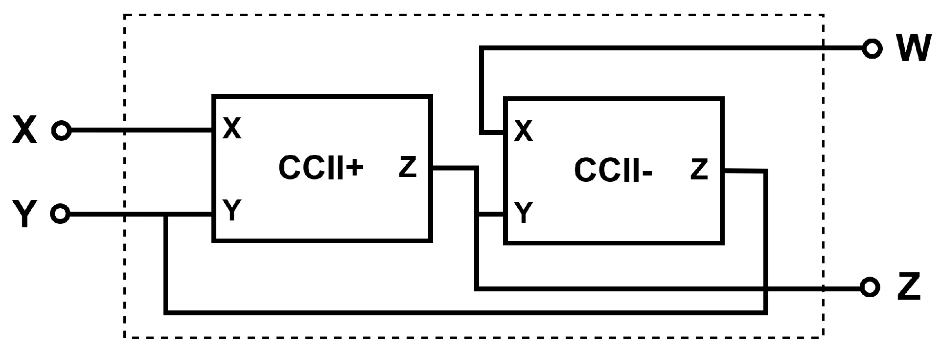
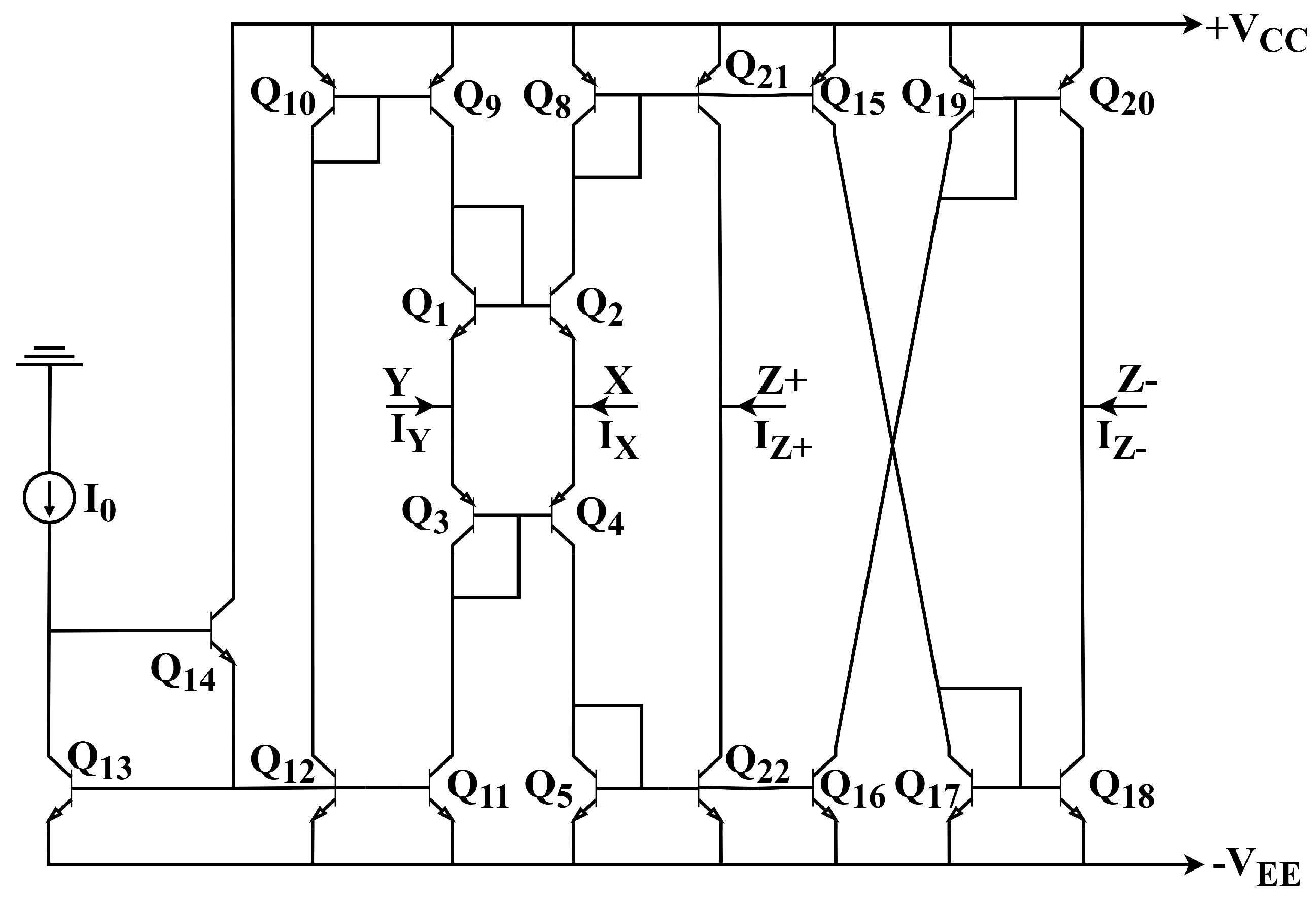
2. Modified Current Feedback Operational Amplifier (MCFOA)

Following Svoboda et al.’s introduction of the CFOA component into academic literature in 1991 [28], Yuce and Minaei proposed the MCFOA structure a few years thereafter [5]. Unlike the CFOA, the MCFOA allows current to flow through its Y-terminal, which is mirrored in the opposite direction at the W-terminal. This characteristic makes designing the MCFOA for CM applications both simpler and more practical. The electrical relationships involving currents and potentials at the corresponding nodes of the MCFOA are expressed through Equation (4), while its structural representation is depicted in Figure 1.
I Z = β 1 I X , I Y = β 2 I W V X = α 1 V Y , V W = α 2 V Z
The coefficients α 1 and α 2 given in Equation (4) represent frequency-independent non-ideal voltage gains, while β 1 and β 2 denote frequency-independent non-ideal current gains. Under ideal conditions, these coefficient values are assumed to be equal to one.
The MCFOA element is constructed as a calibration of the CCII element, as shown in Figure 2 [29]. To enhance the suitability of the structure for CM applications, current-controlled dual output current conveyors (DO-CCCII) replaced the CCII element. The DO-CCCII, featuring dual outputs (+Z and −Zterminals), offers designers flexibility to accommodate specific design needs. Additionally, to improve the compatibility of the DO-CCCII element with CM operations, a BJT-based internal structure was implemented, as depicted in Figure 3. Low-value DC current and voltage sources were employed to operate this configuration (see Section 4).

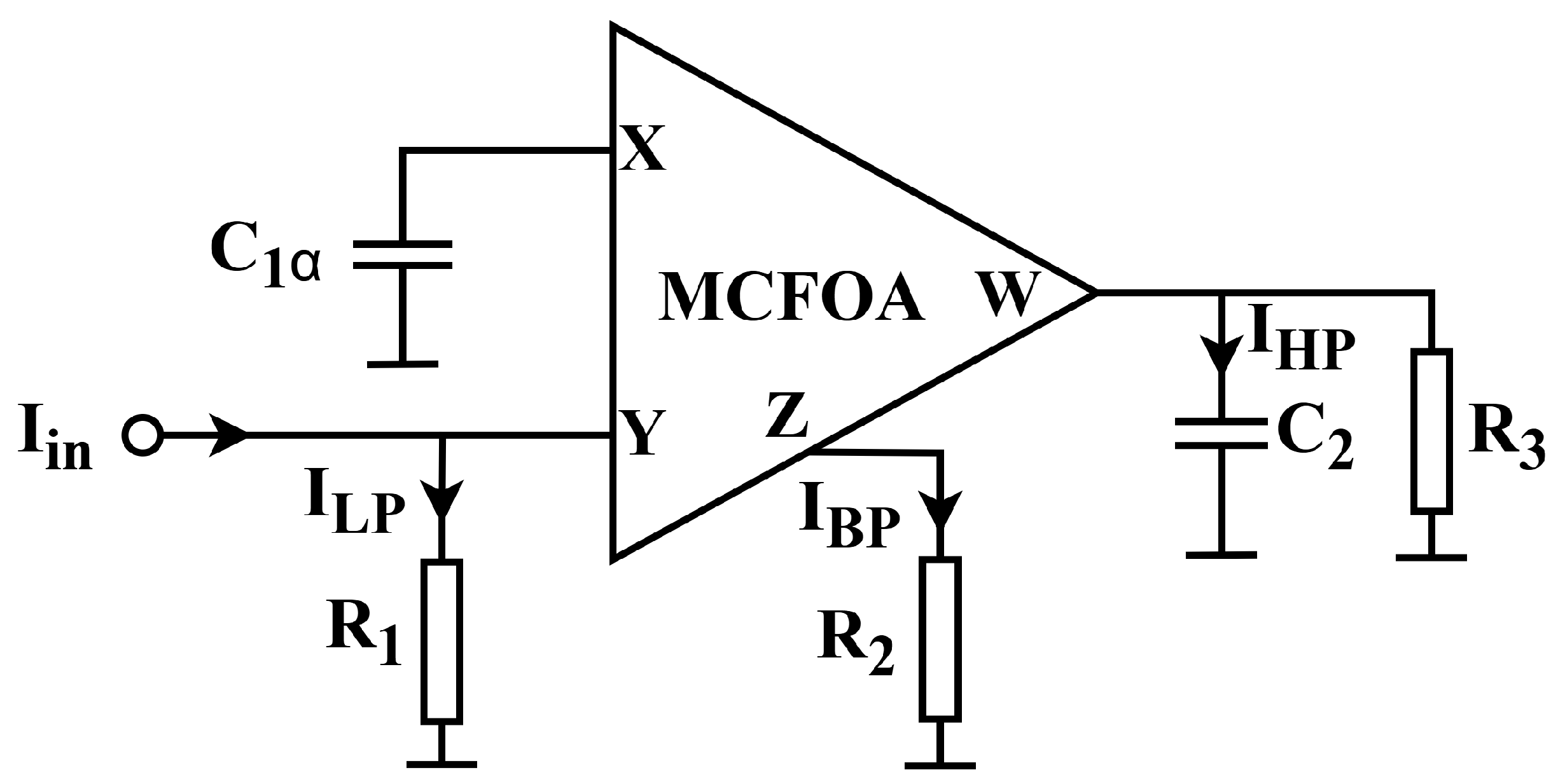
3. MCFOA-Based CM and Fractional-Order Multifunction Filter Circuit

Analog filter circuits designed using fractional-order calculus and various active components have gained increasing attention in recent years [1,2,3,4,6,7,8,9,10,11,12,13,14,15,16,17,18,19,20,21,22,23,24,25,26,27,30]. Multifunction filter circuits, which incorporate a reduced set of active as well as passive components and simultaneously generate multiple filter outputs (such as LP, HP, and BP), serve as notable examples of structures designed with fractional-order calculus. The multifunction form of the transfer function for a dynamic filtering structure incorporating a single fractional-order component, specifically of order 1 + α , is presented within Equation (5) [12].
H ( s ) = I o u t I i n = c s 1 + α + d s α + e s 1 + α + a s α + b = N ( s ) s 1 + α + a s α + b
In this context, a , b , c , d , and e denote constant coefficients, whereas α signifies the fractional derivative order.
The amplitude and spectral characteristics of the fractional-order multifunction filtering system are obtained through the substitution of s = j ω into Equation (5), and these characteristics are expressed in Equations (6) and (7), respectively.
D ( j ω , 1 + α ) = ω 1 + α cos 1 + α π 2 + a ω α cos α π 2 + b + j ω 1 + α sin 1 + α π 2 + j a ω α sin α π 2
D ( j ω , 1 + α ) 2 = ω 2 ( 1 + α ) + a 2 ω 1 + α + 2 a ω 3 α cos α π 2 + 2 a b ω α cos α π 2 + 2 b ω 2 ( 1 + α ) cos 2 α π 2 + b 2
In this study, an original CM fractional-order multifunction filter topology based on MCFOA is presented. The topology enables the simultaneous realization of FO-LPF, FO-HPF, and FO-BPF outputs using a single MCFOA. The proposed filter configuration is depicted in Figure 4. As can be observed from the same figure, the circuit exhibits a relatively simple structure comprising a limited number of components. The overall mathematical model describing the filtering behavior is presented in Equation (8).
I o u t I i n = N ( s ) s 1 + α + 1 C 2 R 3 s α + 1 C 1 α C 2 R 1 R 2
The cut-off frequency ( ω 0 ) and quality factor (Q) of the developed filtering system are identical for all filter outputs and are provided in Equation (9).
ω 0 = 1 C 1 α C 2 R 1 R 2 1 / 1 + α and Q = C 2 R 3 2 C 1 α R 1 R 2 1 / 1 + α
The mathematical expressions governing the filter responses are obtained through the interactions among circuit components and the parameters N ( s ) , a , and b presented in Equation (5). These interactions are concisely presented within Table 2.
The designed filter circuit has been fractionalized through the fractional-order capacitor ( C 1 α ). Utilizing the Oustaloup approximation tool, a fractional-order capacitor was realized owing to its enhanced efficiency in shaping the magnitude characteristics of filtering systems. This approximation tool was realized through a Foster type-I RC configuration, which is optimally structured to incorporate a reduced set of passive components and closely aligns with real-world modeling. The network derived using the n-th order Oustaloup approximation tool is illustrated in Figure 5, and the corresponding resistor and capacitor values are calculated based on Equation (10). In Equation (10), the terms represent residues, gains, and poles [30].
R 0 = k , R i = r i p i , C i = 1 r i ( i = 1 , 2 , , n )

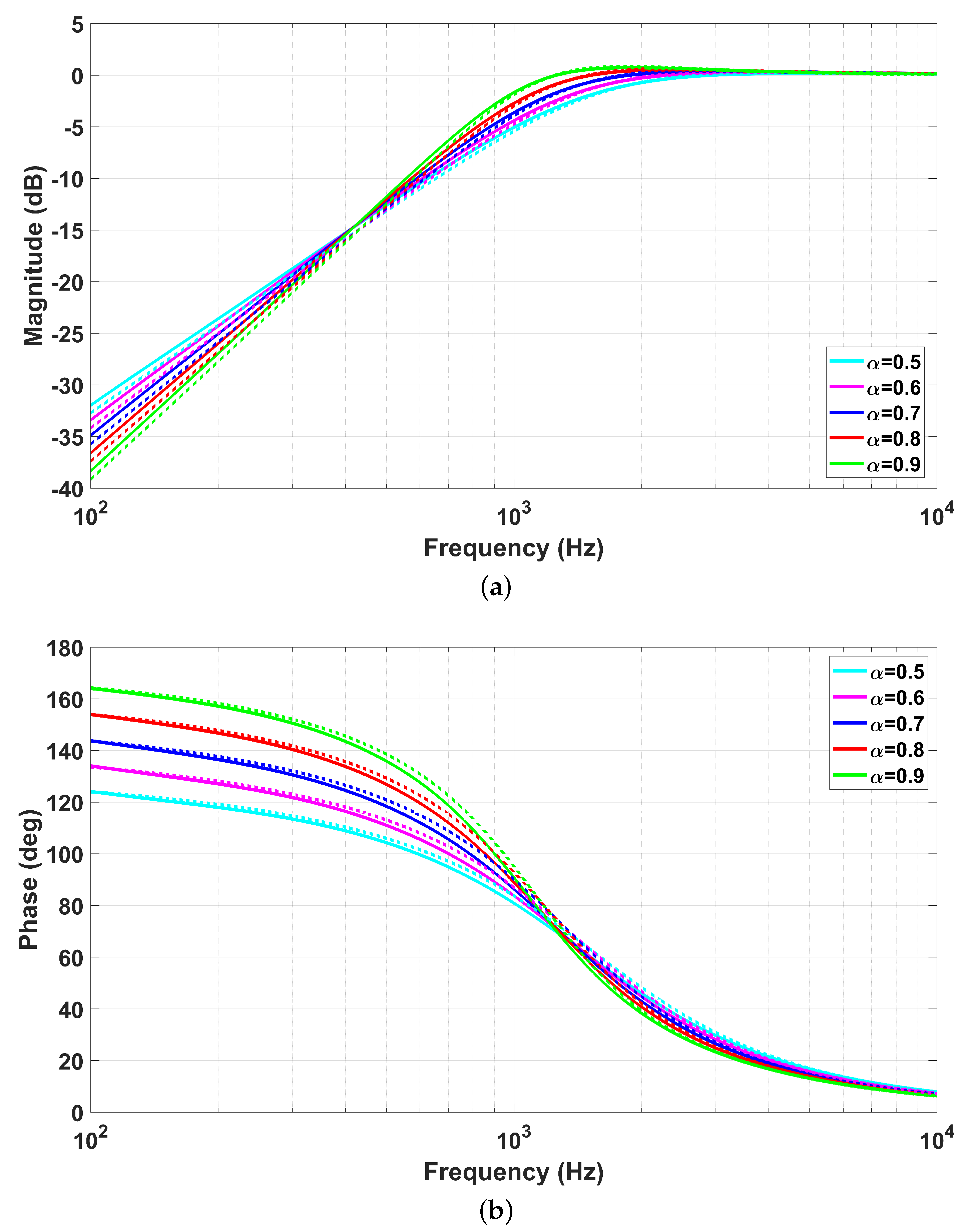
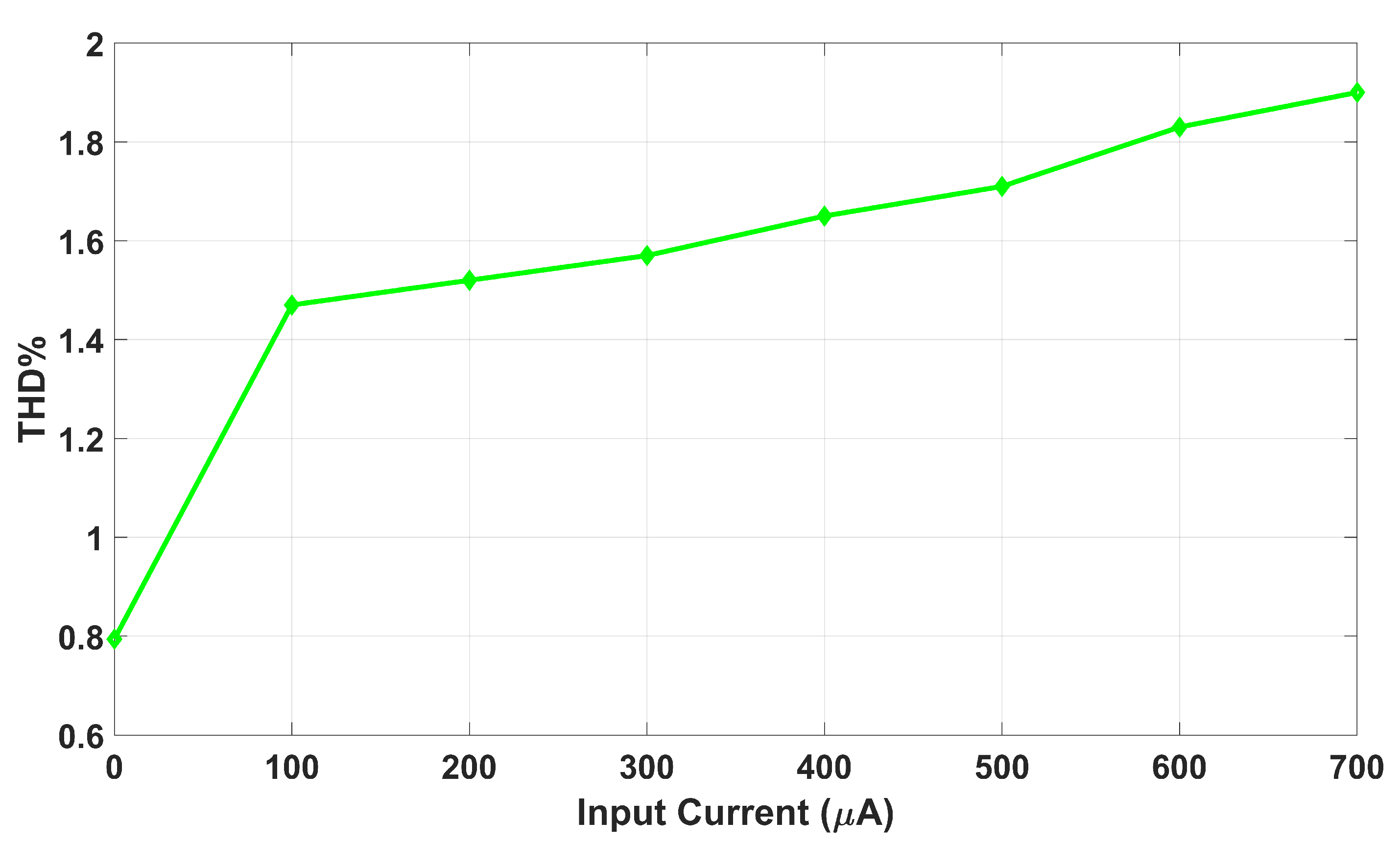
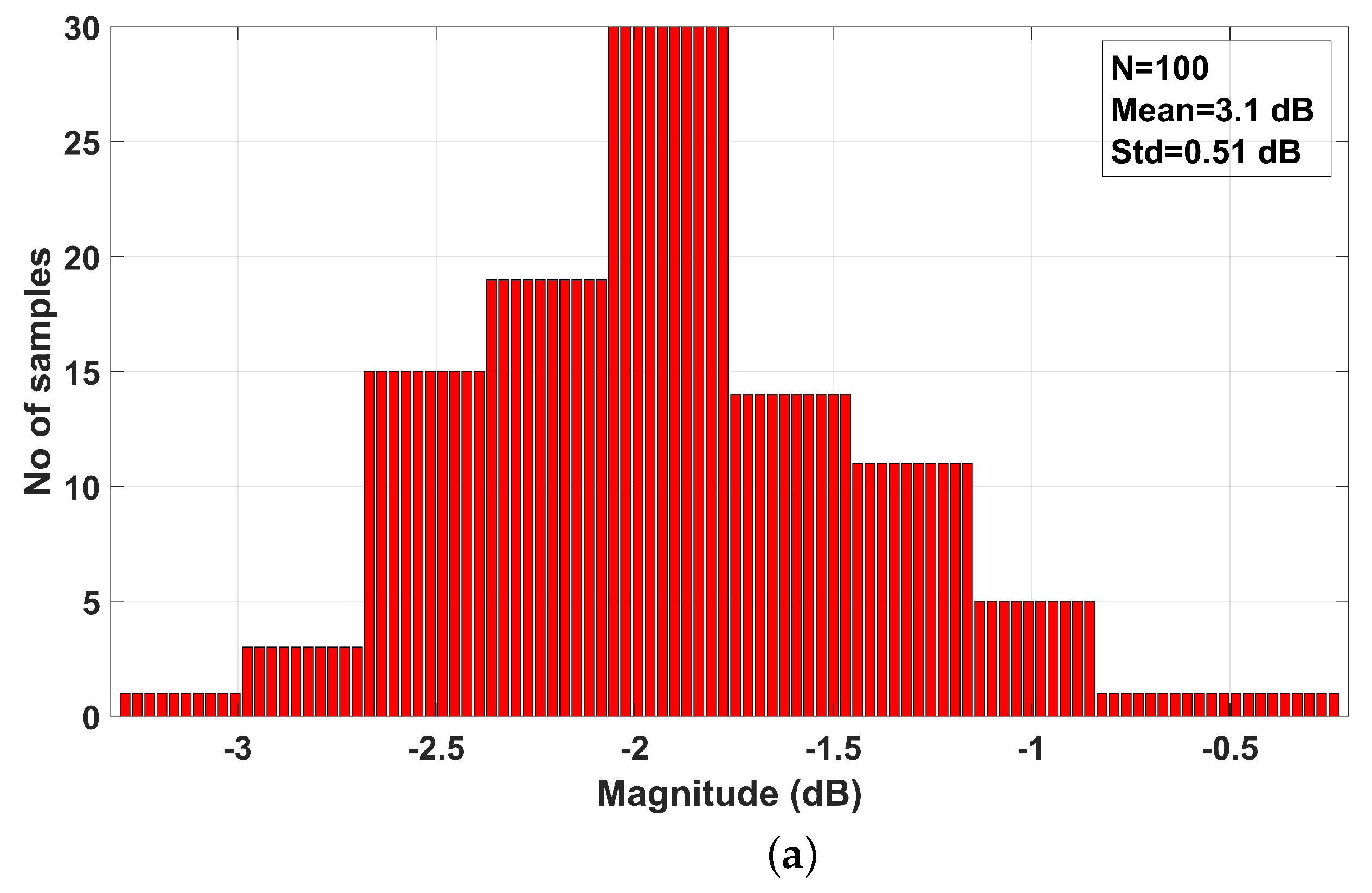
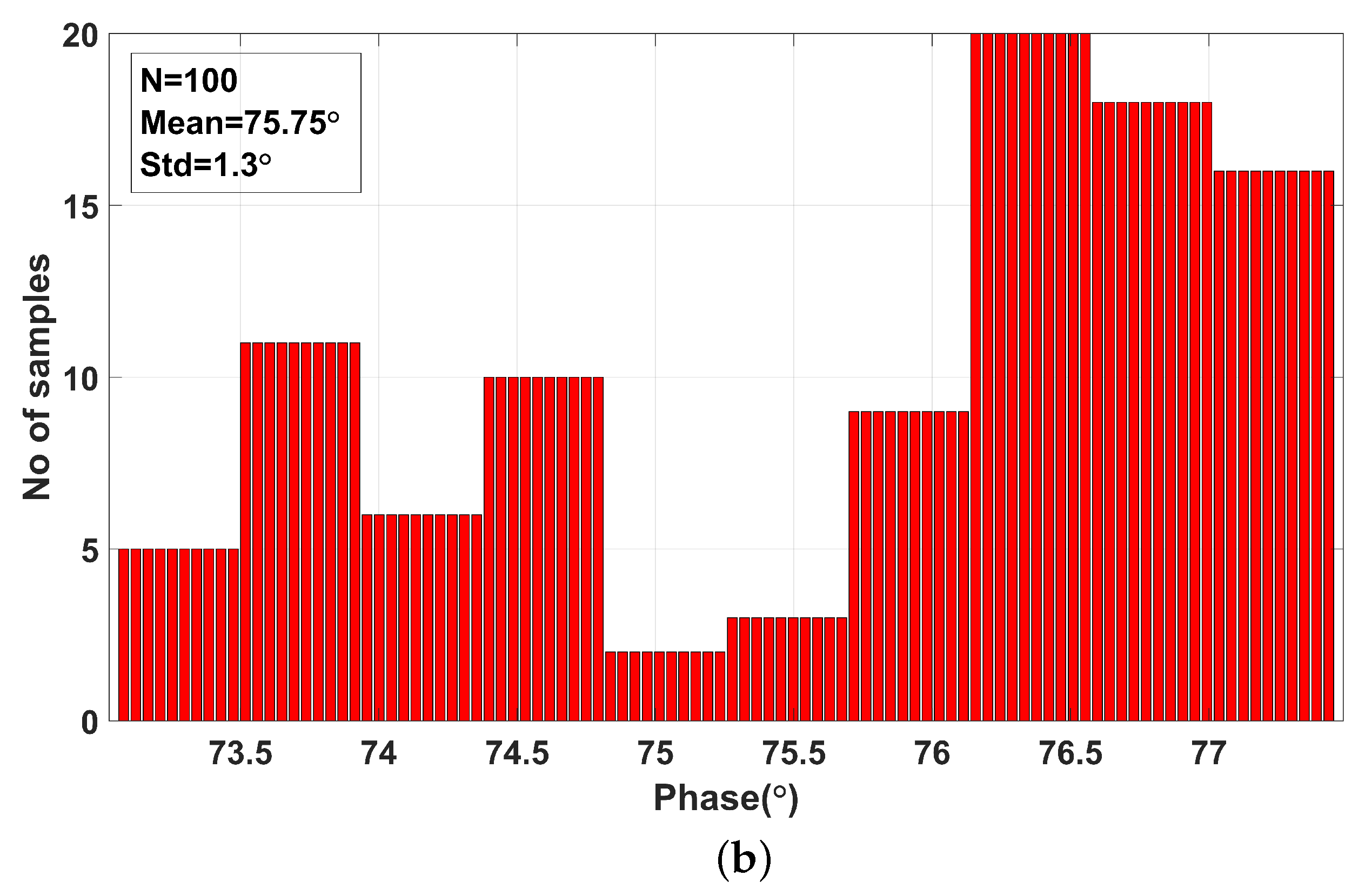
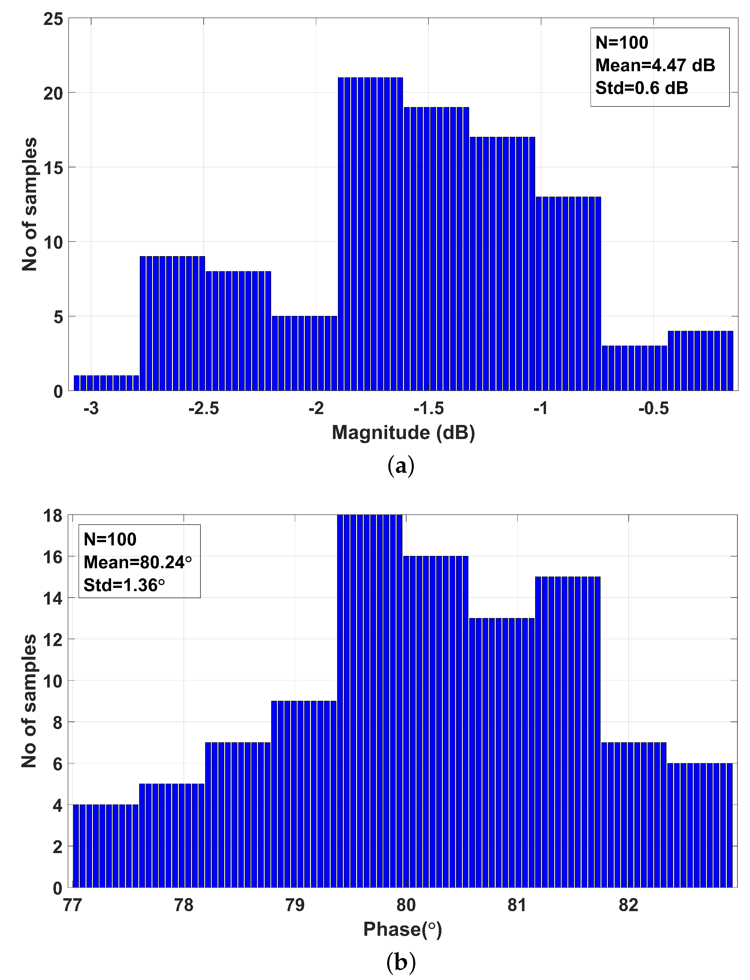
4. Results of the CM Fractional-Order Multifunction Filter Circuit Designed Based on MCFOA

Within this research, a novel CM fractional-order multifunction filter topology has been introduced. The proposed topology in the literature achieves simultaneous FO-LPF, FO-HPF, and FO-BPF outputs using a single MCFOA component with a minimal number of grounded passive components. The MCFOA component is constructed via the configuration applied to the DO-CCCII structure, as illustrated within Figure 2. The DO-CCCII element, in turn, is designed based on the internal structure shown in Figure 3, utilizing a BJT-based implementation. In the internal structure, non-ideal PNP (PR100N) and NPN (NR100N) transistors were employed, and the characteristic parameters related to these transistors were documented in the research by Sen et al. (2024) [1]. Additionally, for the proper operation of the internal structure, power supply voltages must be set to + V E E = V C C = 2.5 V, and the bias current sources should be I 0 = 13 μ A. The parameter specifications of the passive elements within the designed system are determined as R 1 = R 2 = R 3 = 30 k Ω , C 1 α = 5 nF / s 1 α , and C 2 = 5 nF . The filtering system was simulated utilizing these parameters in the PSpice environment. The obtained results validated the accuracy of the system responses, with the observed cut-off point identified at 1 kHz.
The developed filtering configuration integrates a fractional-order capacitor ( C 1 α ), enabling fractional-order operation. In this study, fractional-order capacitors were implemented through a fifth-order Oustaloup approximation method, structured as a Foster type-I RC configuration (see Figure 5). RC configurations of Foster type-I were formulated for modeling distinct fractional orders ( α = 0.5 , 0.6 , 0.7 , 0.8 , and 0.9 ). The required passive component values for these networks were calculated based on Equation (10). To ensure that the designed fractional-order multifunction filter circuit can be implemented not only in simulations but also in practical applications, the calculated passive component values were adjusted to align with the standardized E96 resistor series specified by IEC 60063. This adjustment increased the availability of the passive components in the market. The finalized passive element parameters are provided within Table 3. The RC configurations of Foster type-I associated with the specified fractional-orders were simulated in PSpice software (OrCAD Capture CIS 2022 Version 17.4-2022) (see Figure 6), and the simulation results demonstrated that the networks could operate effectively within the VLF band.
The magnitude characteristics of all filtering outputs (LP, HP, and BP) corresponding to the integer-order case ( α = 1.0 ) of the introduced CM fractional-order multifunction filtering system reported in the literature are depicted in Figure 7.
The magnitude and phase characteristics of the FO-LPF output, obtained separately in the developed CM fractional-order multifunction filtering system, for distinct values of fractional order ( α = 0.5 , 0.6 , 0.7 , 0.8 , and 0.9 ), are illustrated within Figure 8. In this representation, solid curves denote the simulated characteristics of filtering outputs, whereas dashed curves correspond to analytical results derived from Equation (8).
The magnitude and phase characteristics of the FO-HPF response, separately derived for distinct fractional-order values ( α = 0.5 , 0.6 , 0.7 , 0.8 , and 0.9 ) in the developed CM fractional-order multifunction filtering system, are presented in Figure 9. Within the illustration, solid curves denote simulated responses for filtering outputs, whereas dashed curves signify theoretical predictions derived from Equation (8), corresponding to the simulation results.
The magnitude and phase responses of the FO-BPF output, obtained separately for each fractional order ( α = 0.5 , 0.6 , 0.7 , 0.8 , and 0.9 ) within the proposed CM fractional-order multifunction filtering system, are depicted in Figure 10. Within this representation, solid lines denote the numerically obtained responses for filtering outputs, whereas dashed lines illustrate analytical predictions derived from Equation (8), corresponding to computational results. Moreover, as observed in Figure 8, Figure 9 and Figure 10, the simulation responses of the designed filter circuit closely align with their theoretical counterparts. This result demonstrates that the filter outputs perform exceptionally well.
Low Total Harmonic Distortion (THD) values are desirable in analog filter circuits, as a low THD indicates a minimal distortion of the input signal, resulting in a purer output signal. In this study, THD values were measured for the designed filter circuit by applying sinusoidal signals with amplitudes ranging from 0.05 μ A to 700 μ A to the input of the FO-BPF ( 1 + α = 1.9 ) output. The excitation frequency, corresponding to the cut-off frequency (1 kHz), was adjusted accordingly. The measurement results are presented in the graph shown in Figure 11, clearly demonstrating that the circuit maintains low THD values (<2%), indicating high performance.
In this study, filter applications operating in the sensitive radio frequency (RF) range (3 kHz to 300 GHz) are expected to have a wide dynamic range (60 dB to 100 dB). In analog filter circuits, the dynamic range is defined as the proportion between the maximum applied excitation amplitude (700 μ A) and the minimum detectable excitation level (0.05 μ A) that can be introduced into the circuit without inducing any distortion or noise in the signal. This ratio is calculated using Equation (11). The calculation results demonstrate that the filter circuit possesses a wide dynamic range (>80 dB), and can be effectively utilized within the VLF band.
Δ R = 20 log I I N M A X I I N M I N
Numerical analysis demonstrated that power consumption remained below 2 mW under a 2.5 V single-source configuration. Additionally, a noise evaluation was conducted on the filtering system. The analysis showed that the total output noise value was 267 pV / Hz , while the input noise value was measured as 67.2 pA / Hz . The data obtained from these measurements indicate that the designed filter circuit is a suitable alternative for applications requiring low-power and low-voltage operation.
Monte Carlo analysis is applied in analog filter circuits to examine the impact of random variations in component tolerances and other parameters on circuit performance. In this study, for the developed multifunction filtering configuration, a statistical evaluation was carried out via the FO-BPF ( 1 + α = 1.9 ) output using PSpice, employing a Monte Carlo analysis (N = 100 runs). During the analysis, the saturation currents ( I S ), early voltages ( V A F ), and internal resistances ( R B , R C , and R E ) of the BJT were considered within a tolerance of 20 % . The results of the analysis are presented through magnitude and phase graphs provided within Figure 12.
After restoring this BJT parameter values, a new Monte Carlo analysis was performed on the same filter output, considering variations in all passive components, including those associated with the Foster type-I RC configuration. These resistor values were varied with a tolerance of 10 % , and the capacitance levels were adjusted within a 20 % tolerance range to evaluate the sensitivity of the cut-off frequency. The findings of the analysis are depicted through the graphical representation of magnitude and phase characteristics in Figure 13.
Monte Carlo analysis holds critical importance, particularly for applications requiring high precision, such as the VLF band considered in this study. This analysis enabled the evaluation of the circuit’s reliability, stability, and resilience against tolerances in the manufacturing process. Upon examining the analyses and the resulting graphs, it is evident that the designed CM fractional-order and MCFOA-based multifunction filter circuit successfully meets the required level of precision.

5. Discussion

The MCFOA-based, CM, and fractional-order multifunction filter circuit presented in this study distinguishes itself from existing designs in the literature through its simplified structure, high performance, and broad application potential. The proposed configuration was implemented by employing just one active element (MCFOA) along with a limited set of completely grounded passive components. This approach not only reduces circuit complexity but also ensures compatibility with integrated circuit (IC) design, which is particularly advantageous for analog systems requiring limited space and low power consumption. The fractional-order behavior enabled more precise control over the transition and stopband slopes of the filter, enhancing design flexibility and allowing the customization of the frequency response to meet specific user requirements. By implementing the fractional-order capacitors via the Oustaloup approximation and Foster type-I RC network, the design achieves an extended frequency characterization for various fractional orders ( α ), demonstrating effective operation within the VLF band.
Simulation results confirmed that the filter responses (FO-LPF, FO-HPF, and FO-BPF) closely match their theoretical models. Performance metrics such as a low THD, a wide dynamic range, and low input/output noise indicate that the circuit is suitable for both precision signal processing and noise-sensitive applications. Additionally, Monte Carlo analysis revealed that the proposed filter exhibits high stability against parameter variations in both active and passive components. These findings validate that the filter can provide stable and reliable performance not only in simulation environments but also in practical implementations.

6. Conclusions

In this study, a CM and fractional-order ( 1 + α ) multifunction filter circuit based on the MCFOA was designed, and both theoretical analyses and simulations were performed using the PSpice environment. The strong agreement between the simulation results and theoretical models confirms the accuracy and reliability of the proposed circuit. The design stands out not only for its structural simplicity but also for its robust performance characteristics. The principal merits associated with the presented filter design may be outlined as follows:
  • This proposed design enables the simultaneous generation of FO-LPF, FO-HPF, and FO-BPF outputs within a single circuit structure, thereby providing multifunctional filtering capability.
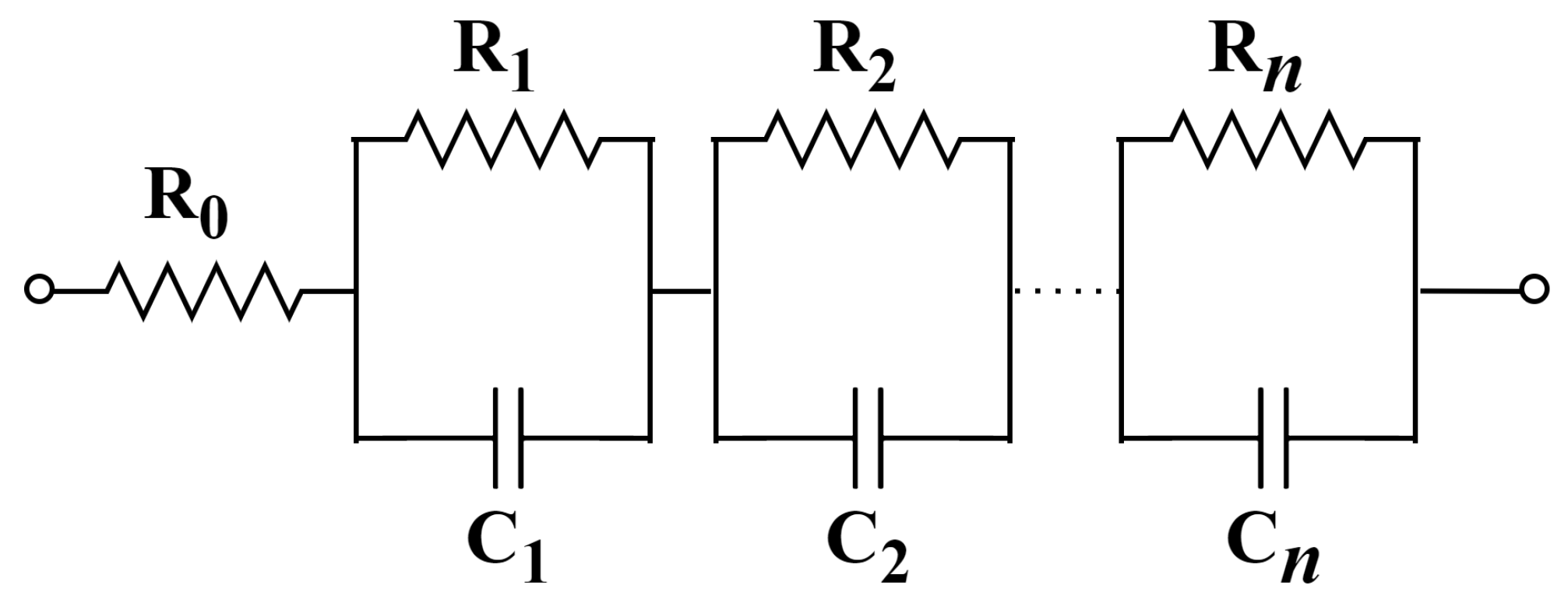
  • The filter circuit, rendered fractional-order by incorporating a fractional-order capacitor, was designed using passive component values (including those in Foster type-I RC networks) approximated based on the IEC 60063 E96 standard [31] series, thereby improving its feasibility for real-world application.
  • Thanks to its fractional-order design, the transition and stopband slopes can be controlled via the α parameter, offering the designer a high degree of flexibility in shaping the frequency response.
  • Simulation analyses conducted in the PSpice environment demonstrated that the filter circuit meets key performance criteria such as a low THD, a wide dynamic range, low noise, and low power consumption. Moreover, Monte Carlo analyses confirmed the circuit’s high robustness against variations in both active and passive components.
In conclusion, the proposed fractional-order multifunction filter structure is considered a high-performance and structurally simple solution that can be effectively utilized in various fields such as low-frequency communication systems, precision signal processing applications, and integrated systems.

Author Contributions

Methodology, formal analysis, F.S.; writing—original draft, F.S. and A.K.; supervision, A.K.; writing—review and editing, F.S. and A.K. The authors contributed equally and significantly in writing this paper. All authors have read and agreed to the published version of the manuscript.

Funding

This research received no external funding.

Data Availability Statement

No new data were created or analyzed in this study. Data sharing is not applicable to this article.

Conflicts of Interest

The authors declare that they have no known competing financial interests or personal relationships that could have appeared to influence the work reported in this paper.

References

  1. Sen, F.; Kircay, A.; Cobb, B.S.; Akgul, A. MO-CCCII-Based Single-Input Multi-Output (SIMO) Current-Mode Fractional-Order Universal and Shelving Filter. Fractal Fract. 2024, 8, 181. [Google Scholar] [CrossRef]
  2. He, X.; Hu, Z. Optimization design of fractional-order Chebyshev lowpass filters based on genetic algorithm. Int. J. Circuit Theory Appl. 2022, 50, 1420–1441. [Google Scholar] [CrossRef]
  3. Sen, F.; Kircay, A.; Cobb, B.S.; Karci, H. Current-mode fractional-order shelving filters using MCFOA for acoustic applications. AEU-Int. J. Electron. Commun. 2023, 163, 154608. [Google Scholar] [CrossRef]
  4. Kubanek, D.; Freeborn, T.; Koton, J.; Herencsar, N. Evaluation of (1 + α) fractional-order approximated Butterworth high-pass and band-pass filter transfer functions. Elektron. Elektrotechnika 2018, 24, 37–41. [Google Scholar] [CrossRef]
  5. Yuce, E.; Minaei, S. A modified CFOA and its applications to simulated inductors, capacitance multipliers, and analog filters. IEEE Trans. Circuits Syst. Regul. Pap. 2008, 55, 266–275. [Google Scholar] [CrossRef]
  6. Said, L.A.; Radwan, A.G.; Madian, A.H.; Soliman, A.M. Fractional-order inverting and non-inverting filters based on CFOA. In Proceedings of the 2016 39th International Conference on Telecommunications and Signal Processing (TSP), Vienna, Austria, 27–29 June 2016; pp. 599–602. [Google Scholar]
  7. Khateb, F.; Kubánek, D.; Tsirimokou, G.; Psychalinos, C. Fractional-order filters based on low-voltage DDCCs. Microelectron. J. 2016, 50, 50–59. [Google Scholar] [CrossRef]
  8. Dvorak, J.; Langhammer, L.; Jerabek, J.; Koton, J.; Sotner, R.; Polak, J. Electronically tunable fractional-order low-pass filter with current followers. In Proceedings of the 2016 39th International Conference on Telecommunications and Signal Processing (TSP), Vienna, Austria, 27–29 June 2016; pp. 587–592. [Google Scholar]
  9. Koton, J.; Jerabek, J.; Herencsar, N.; Kubanek, D. Current conveyors in current-mode circuits approximating fractional-order low-pass filter. In Proceedings of the 2017 European Conference on Circuit Theory and Design (ECCTD), Catania, Italy, 4–6 September 2017; pp. 1–4. [Google Scholar]
  10. Tsirimokou, G.; Psychalinos, C.; Elwakil, A.S. Fractional-order electronically controlled generalized filters. Int. J. Circuit Theory Appl. 2017, 45, 595–612. [Google Scholar] [CrossRef]
  11. Verma, R.; Pandey, N.; Pandey, R. Electronically tunable fractional order filter. Arab. J. Sci. Eng. 2017, 42, 3409–3422. [Google Scholar] [CrossRef]
  12. Hamed, E.M.; AbdelAty, A.M.; Said, L.A.; Radwan, A.G. Effect of different approximation techniques on fractional-order KHN filter design. Circuits Syst. Signal Process. 2017, 37, 5222–5252. [Google Scholar] [CrossRef]
  13. Kubanek, D.; Freeborn, T.; Koton, J. Fractional-order band-pass filter design using fractional-characteristic specimen functions. Microelectron. J. 2019, 86, 77–86. [Google Scholar] [CrossRef]
  14. Dvorak, J.; Jerabek, J.; Polesakova, Z.; Kubanek, D.; Blazek, P. Multifunctional electronically reconfigurable and tunable fractional-order filter. Elektron. Elektrotechnika 2019, 25, 26–30. [Google Scholar] [CrossRef]
  15. Hassanein, A.M.; Soltan, A.; Said, L.A.; Madian, A.H.; Radwan, A.G. Analysis and design of fractional-order low-pass filter with three elements of independent orders. In Proceedings of the 2019 Novel Intelligent and Leading Emerging Sciences Conference (NILES), Giza, Egypt, 28–30 October 2019; Volume 1, pp. 218–221. [Google Scholar]
  16. Langhammer, L.; Dvorak, J.; Sotner, R.; Jerabek, J.; Bertsias, P. Reconnection–less reconfigurable low–pass filtering topology suitable for higher–order fractional–order design. J. Adv. Res. 2020, 25, 257–274. [Google Scholar] [CrossRef] [PubMed]
  17. Swain, S.; Biswal, K.; Tripathy, M.C.; Kar, S.K. Performance analysis of fractional order Sallen-Key high-pass filter using fractional capacitors. In Proceedings of the 2020 International conference on computational intelligence for smart power system and sustainable energy (CISPSSE), Keonjhar, India, 29–31 July 2020; pp. 1–5. [Google Scholar]
  18. Kaur, G.; Ansari, A.Q.; Hashmi, M.S. Analysis and investigation of CDBA based fractional-order filters. Analog. Integr. Circuits Signal Process. 2020, 105, 111–124. [Google Scholar] [CrossRef]
  19. Ahmed, O.I.; Yassin, H.M.; Said, L.A.; Psychalinos, C.; Radwan, A.G. Implementation and analysis of tunable fractional-order band-pass filter of order 2α. AEU-Int. J. Electron. Commun. 2020, 124, 153343. [Google Scholar] [CrossRef]
  20. Sen, F.; Kircay, A. MO-CCCII based current-mode fractional-order universal filter. J. Circuits, Syst. Comput. 2021, 30, 2150132. [Google Scholar] [CrossRef]
  21. Biswal, K.; Swain, S.; Tripathy, M.C.; Kar, S.K. Re-configurable band-stop and all-pass filter using fractional-order topology. Int. J. Adv. Technol. Eng. Explor. 2022, 9, 1773. [Google Scholar]
  22. Kaur, G.; Ansari, A.Q.; Hashmi, M.S. Complexity reduced design procedure of a fractional order all-pass filter. Wirel. Pers. Commun. 2022, 125, 2515–2535. [Google Scholar] [CrossRef]
  23. Krishna, B.T.; Janarthanan, M. Realization of fractional order lowpass filter using different approximation techniques. Bull. Electr. Eng. Inform. 2023, 12, 3552–3561. [Google Scholar] [CrossRef]
  24. Tasneem, S.; Ranjan, R.K.; Paul, S.K.; Herencsar, N. Power-Efficient Electronically Tunable Fractional-Order Filter. Fractal Fract. 2023, 8, 31. [Google Scholar] [CrossRef]
  25. Biswal, K.; Swain, S.; Tripathy, M.C.; Kar, S.K. Modeling and performance improvement of fractional-order band-pass filter using fractional elements. IETE J. Res. 2023, 69, 2791–2800. [Google Scholar] [CrossRef]
  26. Biswal, K.; Swain, S.; Tripathy, M.C.; Kar, S.K. A high-Q fractional-order twin-T notch filter for low-frequency applications. Sādhanā 2023, 48, 38. [Google Scholar] [CrossRef]
  27. Yokuş, Y.E.; Koton, J.; Sotner, R.; Kartci, A.; Ayten, U.E. A review of the state-of-the-art in fractional-order analog filters. AEU-Int. J. Electron. Commun. 2025, 196, 2791–2800. [Google Scholar] [CrossRef]
  28. Svoboda, J.A.; McGory, L.; Webb, S. Applications of a commercially available current conveyor. Int. J. Electron. Theor. Exp. 2023, 70, 159–164. [Google Scholar] [CrossRef]
  29. Cui, X. A Study of Voltage-Mode and Current-Mode Filters Using Modified Current Feedback Operational Amplifier. Ph.D. Thesis, Concordia University, Montreal, QC, Canada, 2018. [Google Scholar]
  30. Tsirimokou, G. A systematic procedure for deriving RC networks of fractional-order elements emulators using MATLAB. AEU-Int. J. Electron. Commun. 2017, 78, 7–14. [Google Scholar] [CrossRef]
  31. IEC 60063; Preferred Number Series for Resistors and Capacitors (Including E96). International Electrotechnical Commission: Geneva, Switzerland, 2015.
Figure 1. Schematic symbol of the MCFOA element.
Fractalfract 09 00377 g001
Figure 2. Connection configuration of the MCFOA element.
Fractalfract 09 00377 g002
Figure 3. Internal structure of the BJT-based DO-CCCII element [2].
Fractalfract 09 00377 g003
Figure 4. The designed CM fractional-order multifunction filtering structure.
Fractalfract 09 00377 g004
Figure 5. A Foster type-I RC configuration was employed for the realization of the fractional-order capacitor ( C 1 α ).
Fractalfract 09 00377 g005
Figure 6. Impedance characteristics, including (a) magnitude and (b) phase variations, for all Foster type-I RC configurations corresponding to fractional-order values of α = 0.5 , 0.6 , 0.7 , 0.8 and 0.9 .
Fractalfract 09 00377 g006
Figure 7. Simulated (solid line) magnitude characteristics of the integer-order ( 1 + α = 2.0 ) filtering responses of the developed filtering configuration, along with the analytical (dashed line) magnitude characteristics derived from Equation (8).
Fractalfract 09 00377 g007
Figure 8. The numerically obtained (a) magnitude and (b) phase characteristics for the FO-LPF response in the developed filtering configuration, where the simulated results (solid line) are compared with the analytical predictions (dashed line) derived from Equation (8).
Fractalfract 09 00377 g008
Figure 9. The numerically obtained (a) magnitude and (b) phase characteristics for the FO-HPF response in the developed filtering configuration, where the computed data (solid line) are compared with the analytical estimations (dashed line) derived from Equation (8).
Fractalfract 09 00377 g009
Figure 10. The numerically obtained (a) magnitude and (b) phase characteristics for the FO-BPF response in the developed filtering configuration, where the computed data (solid line) are compared with the analytical estimations (dashed line) derived from Equation (8).
Fractalfract 09 00377 g010
Figure 11. THD (%) graph of the designed filter circuit over the FO-BPF ( 1 + α = 1.9 ) output.
Fractalfract 09 00377 g011
Figure 12. The Monte Carlo analysis findings of the (a) magnitude and (b) phase characteristics of the FO−BPF (1 + α = 1.9) filter response under varying BJT parameter deviations at the designated cut−off frequency f 0 = 1 kHz.
Fractalfract 09 00377 g012aFractalfract 09 00377 g012b
Figure 13. The Monte Carlo analysis findings regarding (a) magnitude and (b) phase characteristics at the FO-BPF ( 1 + α = 1.9 ) output under varying tolerance levels of passive elements at the designated cut-off frequency f 0 = 1 kHz.
Fractalfract 09 00377 g013
Table 1. Comparative characteristics of classical filter responses implemented using fractional calculus.
Ref.Active
Block
ConfigurationMode
of Opr.
Filter TypeNo. of
Passive Elements
Using
FC
Power
Cons.
Dynamic
Range
NoiseTHD
(%)
R (Gnd.)C (Gnd.)
[6]+CFOA (3)
+CFOA (3)
NA+VM
+VM
+Inverting
FO-LPF,
FO-HPF and
FO-BPF
+Non-Inverting
FO-LPF,
FO-HPF and
FO-BPF
+6 (3)
+5 (3)
-+ 2
+ 2
NANANANA
[7]DDCC (5)MOSFETsVMFO-LPF7 (7)3 (3)-37 μ ANANANA
[8]MO-CF (3)
and
ACA (5)
NACMFO-LPF3 (0)3 (3)-NANANANA
[9]+CCII (3)
and
DDCC (1)
+CCII (1)
and
DDCC(3)
NACMFO-LPF+7 (7)
+5 (5)
+3 (3)
+3 (3)
-NANANANA
[10]OTA (11)MOSFETsCMFO-LPF,
FO-HPF,
FO-BPF and
FO-NPF
-4 (4)-NANANANA
[11]OTA (3)NACMFO-LPF
and
FO-BPF
--2NANANANA
[12]CCII (5)NAVMFO-LPF
and
FO-HPF
6 (3)-2NANANANA
[13]opAmp (3)NAVMTom-Thomas
FO-BPF
6 (0)-2NANANANA
[14]OTA (3)
and
ACA (3)
NACMFO-LPF,
FO-HPF,
FO-BPF AND
FO-NPF
-1 (0)1NANANANA
[15]opAmp (2)NAVMFO-LPF6 (2)-3NANANANA
[16]OTA (4)
and
IOGC-CA (1)
NACMFO-LPF-4 (4)-NANANANA
[17]opAmp (1)NAVMSallen-Key
FO-HPF
2 (1)-2NANANANA
[18]+CDBA (5)
+CDBA (5)
+CDBA (5)
MOSFETsCM+FO-LPF and
FO-BPF
+FO-HPF
+FO-NPF and
FO-APF
+11 (2)
+11 (2)
+12 (2)
+3 (3)
+3 (3)
+3 (3)
-NANANANA
[19]OTA (11)MOSFETsVMFO-BPF-4 (4)-NANANANA
[20]MO-CCII (3)BJTsCMFO-LPF,
FO-HPF,
FO-BPF,
FO-NPF and
FO-APF
2 (2)1 (1)1NANANANA
[21]+opAmp (1)
+opAmp (1)
NAVM+FO-NPF
+FO-APF
+4 (1)
+3 (1)
-+2
+1 and
using
FI
NANANANA
[22]CDBA (4)MOSFETsVMFO-APF11 (1)3 (3)-NANANANA
[23]opAmp (6)NAVMFO-LPF14 (0)3 (0)-NANANANA
[24]VDDDA (3)MOSFETsVMFO-LPFAct.
Res. (2)
3 (3)-663 nWNA691  nV / Hz <4
[25]opAmp (1)NAVMFO-BPF3 (0)-1 and
using
FI
NANANANA
[26]opAmp (1)NAVM+FO-NPF
+FO twin-T NPF
3 (0)-3NANANANA
ProposedMCFOA (1)BJTsCMFO-LPF,
FO-HPF and
FO-BPF
3 (3)1 (1)1<2 mW>80 dB67.2 pA / Hz <2
NA: Not available.
Table 2. Overview of the correlations among circuit parameters and components for transfer function derivation.
ParameterFO-LPFFO-HPFFO-BPF
a 1 C 2 R 3 1 C 2 R 3 1 C 2 R 3
b 1 C 1 α C 2 R 1 R 2 1 C 1 α C 2 R 1 R 2 1 C 1 α C 2 R 1 R 2
N ( s ) 1 C 1 α C 2 R 1 R 2 s 1 + α 1 C 2 R 3 s α
Table 3. Component parameters within a Foster type-I RC framework employed for implementing various non-integer order configurations ( α = 0.5 , 0.6 , 0.7 , 0.8 , and 0.9 ) (1 kHz and C 1 α = 5 nF / s 1 α ).
Fractional-Order ( α )
Pass. Comp.0.50.60.70.80.9
R 0 ( k Ω ) 2.871.650.880.420.15
R 1 ( k Ω ) 6.344.753.3220.887
R 2 ( k Ω ) 8.257.325.94.122.1
R 3 ( k Ω ) 1413.712.710.26.04
R 4 ( k Ω ) 33.240.244.243.230.9
R 5 ( k Ω ) 287549107023206650
C 1 ( nF ) 2.213.164.999.0922.1
C 2 ( nF ) 8.069.5312.419.139.2
C 3 ( nF ) 15.816.218.724.945.3
C 4 ( nF ) 22.620.520.523.235.7
C 5 ( nF ) 26.718.2139.316.81
Disclaimer/Publisher’s Note: The statements, opinions and data contained in all publications are solely those of the individual author(s) and contributor(s) and not of MDPI and/or the editor(s). MDPI and/or the editor(s) disclaim responsibility for any injury to people or property resulting from any ideas, methods, instructions or products referred to in the content.

