Article

A Model-Free Fractional-Order Composite Control Strategy for High-Precision Positioning of Permanent Magnet Synchronous Motor

1
School of Electrical Engineering, Tongling University, Tongling 244061, China
2
Anhui Engineering Research Center of Intelligent Manufacturing of Copper-Based Materials, Tongling 244061, China
3
College of Mathematics and Computer Science, Tongling University, Tongling 244061, China
*
Author to whom correspondence should be addressed.
Fractal Fract. 2025, 9(3), 161; https://doi.org/10.3390/fractalfract9030161
Submission received: 6 February 2025 / Revised: 3 March 2025 / Accepted: 4 March 2025 / Published: 5 March 2025

Abstract

This paper introduces a novel model-free fractional-order composite control methodology specifically designed for precision positioning in permanent magnet synchronous motor (PMSM) drives. The proposed framework ingeniously combines a composite control architecture, featuring a super twisting double fractional-order differential sliding mode controller (STDFDSMC) synergistically integrated with a complementary extended state observer (CESO). The STDFDSMC incorporates an innovative fractional-order double differential sliding mode surface, engineered to deliver superior robustness, enhanced flexibility, and accelerated convergence rates, while simultaneously addressing potential singularity issues. The CESO is implemented to achieve precise estimation and compensation of both intrinsic and extrinsic disturbances affecting PMSM drive systems. Through rigorous application of Lyapunov stability theory, we provide a comprehensive theoretical validation of the closed-loop system’s convergence stability under the proposed control paradigm. Extensive comparative analyses with conventional control methodologies are conducted to substantiate the efficacy of our approach. The comparative results conclusively demonstrate that the proposed control method represents a significant advancement in PMSM drive performance optimization, offering substantial improvements over existing control strategies.

1. Introduction

The progress of electric motor technology has been a pivotal driving force propelling the advancement of numerous industries, with permanent magnet synchronous motor (PMSM) occupying a prominent position owing to their remarkable efficiency, compact design, and superior performance [1,2]. PMSM has been extensively utilized across a wide array of fields, encompassing electric vehicles, industrial automation, aerospace systems, and renewable energy conversions [3,4,5,6]. Among the myriad challenges associated with controlling PMSM, precise positioning emerges as a paramount aspect, especially in applications where high precision and dynamic response are indispensable [7,8]. For decades, traditional control methods, rooted primarily in integer-order dynamics, have prevailed in the field. Nevertheless, as system requirements become increasingly stringent and complex, these conventional methods frequently fall short of delivering the desired performance levels [9,10].
Sliding mode control (SMC) has gained widespread recognition for its exceptional robustness against disturbances and modeling uncertainties, primarily achieved through a high-frequency switching mechanism that drives the system state toward a predefined sliding surface [11,12,13]. Nevertheless, the conventional SMC’s reliance on integer-order dynamics frequently constrains its capacity to fully harness the dynamic characteristics of complex systems [14,15]. One of the major drawbacks of SMC is the chattering phenomenon. This occurs when the system’s state trajectory reaches the sliding mode surface and fails to strictly follow it, instead oscillating around it. Although SMC is robust to parameter variations and external disturbances, its performance can still be affected by certain types of uncertainties, especially if they are not properly compensated for in the control design. The justification for using SMC in this paper lies in its inherent robustness, fast response time, and ability to handle uncertainties and disturbances effectively, which set it apart from other recent advanced nonlinear control schemes like the sigmoid PID controller, brain emotional learning-based intelligent-PID controller, neuroendocrine PID controller, and others [16,17,18,19,20]. These alternative controllers, while effective in their own right, may not offer the same level of robustness and adaptability to varying system dynamics and external disturbances as SMC does, thus highlighting a significant gap that the proposed SMC-based approach aims to fill.
In recent years, fractional-order calculus has emerged as a transformative tool for enhancing control system design, attracting significant scholarly interest [21,22]. Diverging from integer-order calculus, which is confined to whole-number derivatives and integrals, fractional-order calculus extends these principles to include non-integer values. This augmented flexibility enables the creation of controllers that are more adept at capturing the nuanced dynamics present in real-world systems [23,24]. Fractional order control has gained significant attention due to its enhanced flexibility and precision in tuning system parameters compared to traditional integer order control. One notable application is the fractional order PID tuning tool for automatic voltage regulator using marine predators algorithm [25]. Another example is the performance analysis of fractional order fuzzy PID controllers applied to a robotic manipulator. The integration of fractional order terms with fuzzy logic provides a powerful control strategy that can handle the complexities and uncertainties inherent in robotic systems [26]. Furthermore, the synchronization analysis of nabla fractional-order fuzzy neural networks with time delays via nonlinear feedback control showcases the versatility and robustness of fractional order control in complex dynamical systems [27]. By incorporating fractional-order differentiation and integration into the sliding mode framework, fractional-order sliding mode control is developed. This advancement not only expands design versatility but also significantly enhances control performance [28,29,30]. The superior capabilities of fractional-order sliding mode control render it particularly suitable for applications requiring high precision, reliability, and durability, such as converters, prosthetic devices for lower limb amputees, unmanned aerial vehicles, solar photovoltaic systems, and cell micro injection procedures [31,32,33,34,35].
The design of an extended state observer (ESO) typically begins with the formulation of a dynamic model that meticulously captures the evolution of system states and unknown inputs [36]. Utilizing this model, an observer system is subsequently developed to estimate these elements based solely on available measurements. Renowned for its straightforward architecture and robust resilience, the observer is often designed to endure external disturbances and internal uncertainties, ensuring that the estimations remain accurate and dependable even amidst perturbations [37,38]. A pivotal advantage of ESO is its exceptional capability to provide real-time estimates of unknown inputs, which are crucial for implementing advanced control strategies such as adaptive control or disturbance rejection. By continuously monitoring and evaluating these inputs, an ESO empowers the control system to dynamically adjust its behavior, effectively mitigating the impact of disturbances and enhancing overall performance. Moreover, ESO demonstrates remarkable versatility, seamlessly integrating into a broad spectrum of control systems, from linear time-invariant systems to complex nonlinear systems with time-varying dynamics [39,40]. Their adaptability and flexibility render them an indispensable tool for meeting the demands of modern control applications, where precision, robustness, and adaptability are often the keys to success [41,42,43,44].
The primary objective of this research is to demonstrate the viability and superiority of the novel model-free fractional-order composite control technique for achieving precise positioning of PMSM. Through comprehensive simulations, we aim to showcase the controller’s exceptional capability in delivering unparalleled positioning accuracy, robust performance, and rapid dynamic response. This paper introduces a tailored model-free fractional-order composite control approach specifically designed for the positioning of PMSM drives. This innovative method seamlessly integrates a super twisting double fractional-order differential sliding mode controller with a complementary extended state observer (STDFDSMC). The cornerstone of this method resides in a novel STDFDSMC, which is crafted to guarantee robust performance, heightened flexibility, swift convergence, and efficient prevention of singularities. Furthermore, a CESO is utilized to precisely estimate both internal and external disturbances. The comparative validation results of this study are summarized in Table 1. As can be seen from Table 1, the control strategy proposed in this paper is more effective than the traditional control strategy in terms of dynamic response, steady-state response, and disturbance rejection capability.
To the best of our knowledge, no other literature has utilized this method. The key contributions of this paper are as follows:
  • The paper presents a distinctive model-free fractional-order composite control approach, meticulously crafted for the positioning of PMSM drives. This approach harmoniously combines the strengths of fractional-order calculus and model-free control strategies, aiming to propel the performance of PMSM drives to unprecedented levels.
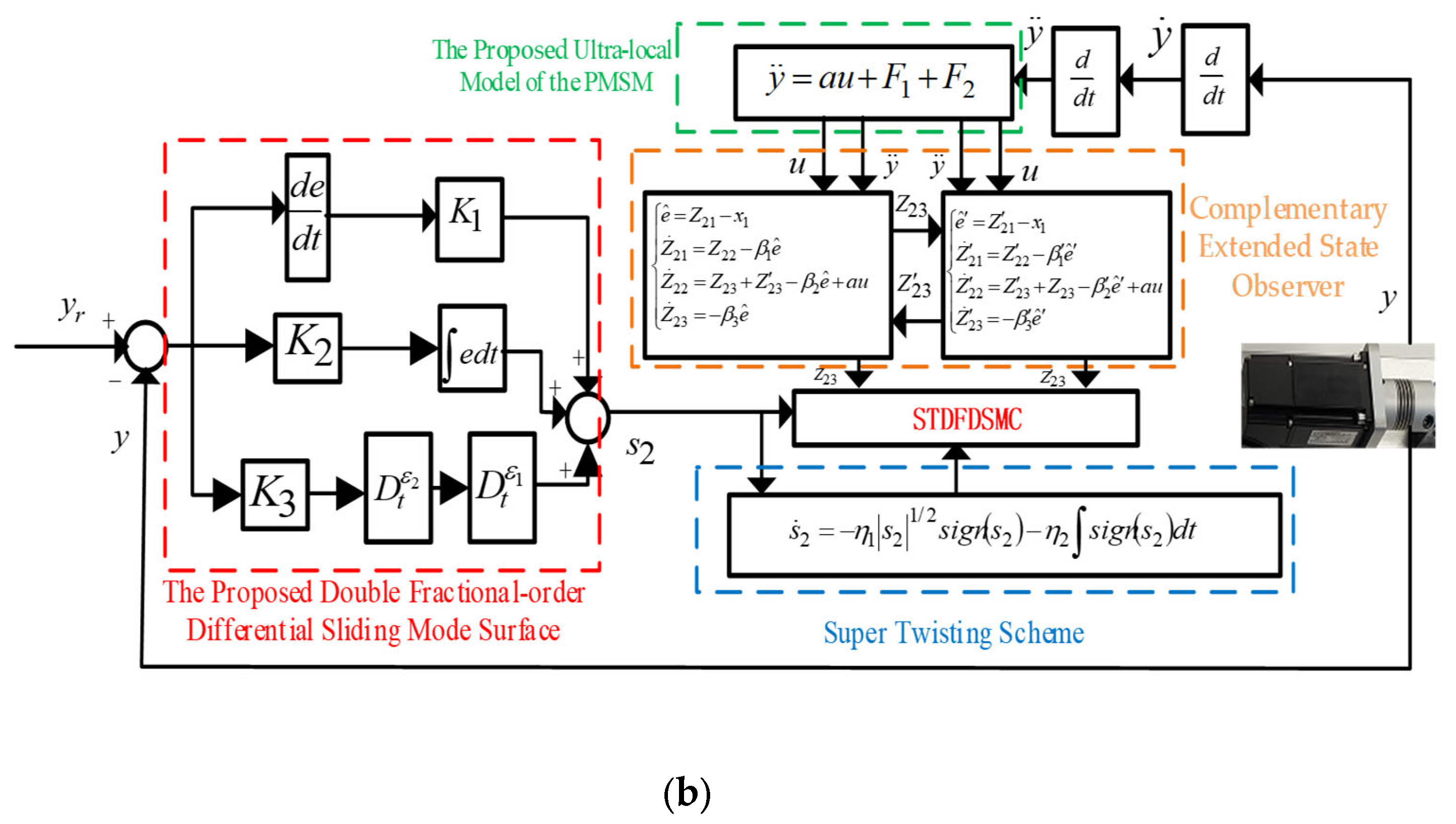
  • The cornerstone of the proposed control method is a novel fractional-order double differential sliding mode surface. This surface ensures remarkable robustness, exceptional adaptability, and swift convergence, while effectively mitigating singularity issues. Additionally, a CESO has been meticulously designed to accurately estimate both internal and external disturbances impacting the PMSM drives, thereby significantly bolstering the system’s overall performance and stability.
  • The paper conducts a stability analysis of the proposed control system utilizing Lyapunov stability theory, confirming the convergence stability of the closed-loop system. Furthermore, comparisons with prevailing control methods are presented to highlight the effectiveness and superiority of the introduced model-free sliding mode composite control approach for PMSM drives.
  • The simulation results have unequivocally verified the efficacy and superiority of our proposed control scheme when benchmarked against existing theories.
These innovation points highlight the substantial contributions of this paper to the realm of PMSM drive control. Notably, the fusion of fractional-order calculus and model-free techniques enhances robustness, flexibility, and stability, marking a significant advancement in the field. In this study, three cases are presented to compare the performance of different control methods for PMSM positions. Case I focuses on steady-state responses, revealing that the proposed STDFDSMC method exhibits the smallest steady-state error compared to conventional controllers. Case II examines dynamic responses, demonstrating that the proposed composite control method significantly reduces tracking error. Case III assesses robustness by introducing external load disturbances, showing that the STDFDSMC method has a considerably shorter recovery time than other methods, highlighting its exceptional robustness.
The structure of the remainder of this paper is as follows: Section 2 introduces the mathematical model that depicts the dynamic response of the PMSM, and provides definitions related to fractional-order calculus and the ultra-local model. Section 3 elaborates on the proposed model-free fractional-order composite control method, accompanied by a stability analysis. A comparative analysis of the results is provided in Section 4. Lastly, Section 5 summarizes the main findings and outlines potential avenues for future research.

2. Modeling and Preliminaries

This section provides a thorough overview of the foundational understanding of the mathematical model that governs the dynamic response of PMSM. It begins by presenting the equation that represents the electromagnetic torque of a PMSM, with references to studies [45,46,47,48] provided for additional context and insight.
T e = 3 2 p n φ f i q + ( L d L q ) i d i q
where T e symbolizes the electromagnetic force of rotation; φ f is the permanent magnet flux linkage; p n is the pole pairs number; L d and L q represent the inductances of the d q axes; i d and i q are the components of armature currents on the d q axes, respectively.
The flux linkage equation, electromagnetic torque equation and voltage equation of salient PMSM are as follows [31]:
φ d = L d i d + φ f φ q = L q i q
u d = R i d + φ ˙ d ω φ q u q = R i q + φ ˙ q + ω φ d
where φ d , φ q are the flux linkages; R is the stator resistance; u d , u q are the stator voltages; ω is the actual mechanical speed.
For a surface-mounted PMSM, L d = L q = L as discussed in this paper, the mathematical model can be articulated as detailed in references [45,46,47,48].
T e T L = J ω ˙ + B ω T e = 3 2 p n φ f i q
θ ˙ = ω ω ˙ = 3 p n φ f 2 J i q B J ω T L J
where θ is the actual mechanical angle position; J , T L , and B are the rotational inertia, the load torque and the friction coefficient, respectively.
With reference to the literature [49,50,51,52], it can be concluded that when there are external disturbances and fluctuations in internal parameters, Equation (5) can be revised as follows:
θ ˙ = ω ω ˙ = T e J 0 i q * + T e J 0 i q i q * Δ J J 0 ω ˙ B J 0 ω T L J
where i q * is the control current signal; J 0 is the invariant part of the moment of inertia; Δ J is the variable component of the moment of inertia.
Equation (6) can be alternatively expressed in the following form:
x ˙ 1 = x 2 x ˙ 2 = f x 2 , u + T e J 0 u + d
where x 1 = θ ; x 2 = ω ; control signal u = i q * ; internal parameter changes f x 2 , u = T e J 0 i q i q * Δ J J 0 ω ˙ B J 0 ω ; external perturbations d = T L J .
Based on references [53,54,55,56,57,58], an overview of the definitions of fractional-order calculus and the ultra-local model are provided. It will delve into how fractional-order integration and differentiation expand upon the principles of integer-order calculus. Among the numerous definitions of fractional-order, the Riemann–Liouville and Caputo definitions are the most prevalent. For the scope of this study, we will utilize the Riemann–Liouville type fractional-order definition. The ε th order Riemann–Liouville fractional derivative of the function f ( t ) is defined as stated in references [53,54].
D t 1 ε t 0 f t = 1 Γ 1 ε d d t t 0 t 1 f τ t τ ε d τ Γ z = 0 e γ γ z 1 d γ
where Γ z is the gamma function; t 1 and t 0 denote the respective upper and lower boundaries for the fractional derivative; 0 < ε < 1 ; D t 1 ε t 0 is simplified and represented as D t ε .
The properties of fractional-order differentiation are as follows, referencing [56] for further details:
d m d t m D t ε f t = D t m + ε f t
D t ε ζ f t + ξ f t = ζ D t ε f t + ξ D t ε f t
where m is an integer; ζ > 0 and ξ > 0 .
For a general nonlinear system, the dynamics can be depicted using the model-free control method outlined in references [56,57,58], in conjunction with the model-free ultra-local model, which is approximately characterized by Equation (11). The ultra-local model of the PMSM, which is independent of the exact mathematical model of the controlled object. The ultra-local model underscores the motor’s real-time response and dynamic behavior, empowering engineers and researchers to develop control systems that are not only robust and adaptive but also fully equipped to manage the inherent uncertainties and variations encountered in real-world PMSM applications.
d n y d t = a u + F
where y is the output term; F represents the unknown structure of the plant, along with any disturbances, which are estimated on the basis of the input signal u and output y ; a R is an assumed constant; n is an integer. The super-local model has received widespread attention and application in the control of PMSM [49,59]. It should be specifically noted that all the controllers designed in this article are presented within the framework of the field-oriented control (FOC) structure for PMSM.

3. Control Strategies and Stability Analysis

3.1. Differential Sliding Mode Controller

To ensure precise tracking of the system states to their desired reference values, we utilize a traditional differential SMC. Now, let us examine the sliding surface employed in traditional differential SMC. Conventionally, the original differential sliding mode surface adopts the following form, as cited in [60,61]:
e = y r y s 1 = K 1 e d t + K 2 e ˙
where K 1 and K 2 are the constants based on positive values; y r is the set point of the system; e is the system error.
Upon taking the time derivative of the differential sliding mode surface, we obtain:
s ˙ 1 = K 1 e + K 2 e ¨
Then, the following reaching law is shown as:
s ˙ 1 = η s i g n s 1
s i g n s 1 = 1 i f s 1 > 0 0 i f s 1 = 0 1 i f s 1 < 0
where η > 0 .
By replacing the value from Equation (14) into Equation (13), we can obtain the following derivation:
K 1 e + K 2 e ¨ = η s i g n s 1
By combining Formula (12), we obtain:
K 1 e + K 2 y ¨ r y ¨ = η s i g n s 1
By integrating the ultra-local model (11), we derive the following expression:
K 1 e + K 2 y ¨ r a u F = η s i g n s 1
Definition 1.
The original differential SMC strategy is designed based on the following structure.
u = 1 a K 1 K 2 e + y ¨ r + η K 2 s i g n s 1
Next, this section aims to demonstrate the stability of the original differential SMC strategy. To achieve this, we select the following Lyapunov function:
V = 1 2 s 1 2
By inserting Equation (19) into Equation (20), we can obtain V ˙ < 0 . Accordingly, the proposed controller can ensure the global asymptotic stability of the system.

3.2. Double Fractional-Order Differential Sliding Mode Controller

Drawing from the sliding mode control framework, the proposed double fractional-order differential sliding mode surface can be characterized as follows:
e = y r y s 2 = K 1 D t ε 2 D t ε 1 e + K 2 e d t + K 3 e ˙
where K 1 , K 2 and K 3 are the constants based on positive values; 0 < ε 1 < 1 ; 0 < ε 2 < 1 .
Based on the properties (9) and (10) of fractional calculus, upon differentiating the proposed double fractional-order differential sliding mode surface, we obtain the following derivative:
s ˙ 2 = K 1 D t 1 + ε 2 D t ε 1 e + K 2 e + K 3 e ¨
Subsequently, by substituting Equation (13) into Equation (22), we can derive the following:
K 1 D t 1 + ε 2 D t ε 1 e + K 2 e + K 3 e ¨ = η s i g n s 2
s i g n s 2 = 1 i f s 2 > 0 0 i f s 2 = 0 1 i f s 2 < 0
By inserting the ultra-local model (11) into the preceding equation, we arrive at:
K 1 D t 1 + ε 2 D t ε 1 e + K 2 e + K 3 y ¨ r y = η s i g n s 2
Based on Equations (11) and (25), we derive the following:
K 1 D t 1 + ε 2 D t ε 1 e + K 2 e + K 3 y ¨ r a u F = η s i g n s 2
Subsequently, we can derive the following conclusion.
u = 1 α K 1 K 3 D t 1 + ε 2 D t ε 1 e + K 1 K 3 e + y ¨ r + F + η K 3 s i g n s 2
Definition 2.
The double fractional-order differential SMC is devised in the following manner:
u = 1 α K 1 K 3 D t 1 + ε 2 D t ε 1 e + K 1 K 3 e + y ¨ r + η K 3 s i g n s 2
To ensure the global asymptotic stability of the system, let us consider the following Lyapunov function candidate:
V = 1 2 s 2 2
The derivative of Equation (29), and by inserting Equation (22) into Equation (29), (29) can be simplified further to:
V ˙ = η s 2 < 0
Expression (30) establishes the negative definiteness of the system, thereby guaranteeing its global asymptotic stability.

3.3. Super Twisting Double Fractional-Order Differential Sliding Mode Controller with the Complementary Extended State Observer

In order to mitigate the chattering phenomenon and bolster the disturbance compensation capabilities, the proposed STDFDSMC incorporates the super twisting algorithm outlined in [62]. The super twisting algorithm is as follows:
s ˙ 2 = η 1 s 2 1 / 2 s i g n s 2 η 2 s i g n s 2 d t
where η 1 > 0 , η 2 > 0 .
Drawing upon the research conducted in (24) and (33), we can reach the following conclusions:
K 1 D t 1 + ε 2 D t ε 1 e + K 2 e + K 3 e ¨ = η 1 s 2 1 / 2 s i g n s 2 η 2 s i g n s 2 d t
By inserting the ultra-local model (11) into the preceding equation, we arrive at the following expression:
K 1 D t 1 + ε 2 D t ε 1 e + K 2 e + K 3 y ¨ r α u F = η 1 s 2 1 / 2 s i g n s 2 η 2 s i g n s 2 d t
Without integrating disturbance observations, the controller can be derived as follows:
u = 1 α K 1 K 3 D t 1 + ε 2 D t ε 1 e + K 2 K 3 e + y ¨ r + F + η 1 K 3 s 2 1 / 2 s i g n s 2 + η 2 K 3 s i g n s 2 d t
Definition 3.
Without integrating disturbance observations, the STDFDSMC is devised according to the following format:
u = 1 α K 1 K 3 D t 1 + ε 2 D t ε 1 e + K 2 K 3 e + y ¨ r + η 1 K 3 s 2 1 / 2 s i g n s 2 + η 2 K 3 s i g n s 2 d t
Drawing inspiration from references [49,58,59,60,61,62], this section aims to demonstrate the stability of the proposed STDFDSMC. According to (11) and (21), we can obtain:
s ˙ 2 = K 1 D t 1 + ε 2 D t ε 1 e + K 2 e + K 3 y ¨ r a u F
Bringing Formula (35) into the above Formula (36), Equation (36) can be reformulated as follows:
s ˙ 2 = η 1 s 2 1 / 2 s i g n s 2 η 2 s i g n s 2 d t K 3 F
Equation (37) can be rearranged as:
s ˙ 2 = η 1 s 2 1 / 2 s i g n s 2 K 3 F + Γ Γ ˙ = η 2 s i g n s 2
Differentiating Equation (38) with respect to time gives:
x ˙ 1 = η 1 x 1 1 / 2 s i g n x 1 + x 2 x ˙ 2 = η 2 s i g n x 1 K 3 F ˙
Let the Lyapunov candidate be:
V = ζ T P ζ ζ T = x 1 1 / 2 s i g n x 1 x 2
where V is a quadratic, strict and robust Lyapunov function; P is a positive definite matrix, The specific configuration of matrix P can be referred to in references [63,64,65,66].
Furthermore, differentiating Equation (40) with respect to time, we can obtain:
V ˙ x 1 1 / 2 ζ T X ζ
where X is a symmetric and positive definite matrix. We can obtain negative semi-definite values. The system can reach the sliding surface at any initial state.
In the design of the PMSM system to address internal parameter variations and external disturbances, this paper presents a new ultra-local model that facilitates efficient approximation.
The innovative ultra-local model for the PMSM is represented as:
d n y d t = a u + F 1 + F 2
where y is the output term; a R is an assumed constant; F 1 is the internal parameter changes; F 2 is the external perturbations; n = 2 .
Equation (44) can be stated as follows:
x ˙ 1 = x 2 x ˙ 2 = a u + x 31 + x 32 x ˙ 31 = F 1 x ˙ 32 = F 2
where x 31 represents the disturbance term F 1 ; x 32 represents the disturbance term F 2 ; F 1 is the fractional-order derivative of the disturbance term x 31 ; F 2 is the fractional-order derivative of the disturbance term x 32 .
Based on Equation (43), the proposed CESO in this study is defined as follows:
e ^ = Z 21 x 1 Z ˙ 21 = Z 22 β 1 e ^ Z ˙ 22 = Z 23 + Z 23 β 2 e ^ + a u Z ˙ 23 = β 3 e ^
where Z 22 is the estimation of x 31 ; Z 22 is the estimation of x 32 ; the stability of the system can be guaranteed when β 1 , β 2 , β 3 , β 1 , β 2 and β 3 are positive constants, the stability proof will be given in detail in the following section.
Drawing inspiration from reference [67], this section aims to demonstrate the stability of the proposed CESO.
Assumption 1.
The total disturbance in the established system is bounded by the following constraint:
F ˜ 1 = x 31 F 1 Ψ F ˜ 2 = x 32 F 2 Ψ F 1 Φ F 2 Φ
where  Ψ ,  Ψ ,  Φ  and  Φ are known positive constant that signify the upper bound of the established system.
For the sake of convenience in expression, set X = Z 21 x 1 Z 22 x 2 Z 23 x 3 , A = β 1 1 0 β 2 0 1 β 3 0 0 , B = 0 0 0 0 1 0 0 0 1 , and Θ = 0 F ˜ 1 F ˜ 2 , then (46) could be expressed by the following:
X ˙ = A X + B Θ
The parameters β 1 , β 2 and β 3 are designed to guarantee that the eigenvalues of the matrix A have negative real parts. To streamline the design process, we can opt to give the characteristic polynomial of a triple characteristic root. Consequently, the characteristic polynomial of A can be expressed as follows:
Δ A = λ 3 + β 1 λ 2 + β 2 λ + β 3
The CESO parameters that we have configured meet the following criteria:
β 1 β 2 β 3 > 0
The roots of the characteristic polynomial of A lie on the left half of the s-plane, guaranteeing Hurwitz stability for the system.
Consequently, the error dynamics represented by Equation (45) are asymptotically stable, ensuring that the estimation error e ˜ 2 converges exponentially to zero, the CESO parameters that we have configured meet the following criteria:
β 1 β 2 β 3 > 0
Therefore, the CESO is stable. In this study, we employ the CESO method to estimate the magnitude of both internal and external disturbances.
Definition 4.
By incorporating the CESO into Equation (36), the proposed STDFDSMC strategy can be reformulated as follows:
u = 1 α K 1 K 3 D t 1 + ε 2 D t ε 1 e + K 2 K 3 e + y ¨ r + η 1 K 3 s 2 1 / 2 s i g n s 2 + η 2 K 3 s i g n s 2 d t Z 23 Z 23
The block diagram illustrating the proposed STDFDSMC scheme is presented in Figure 1. The specific explanation of the FOC of the PMSM control system can be referred to in the literature [68,69,70,71]. The main components of this block diagram are the proposed ultra-local model of the PMSM (42), proposed double fractional-order differential sliding mode surface (21), super-twisting scheme (33), and CESO (44–45). These components collectively constitute the proposed STDFDSMC (51).

4. Comparative Results

In this section, comparative analyses were conducted to assess the speed regulation capabilities of the newly introduced STDFDSMC method. To illustrate the efficacy of our approach, a PMSM position regulation system was implemented in Matlab, utilizing field-oriented control alongside various control strategies. Our proposed control strategy was benchmarked against the original differential SMC and double fractional-order differential SMC methods. During the comparative simulations, all three current loops were governed by PI controllers configured with uniform parameters. Furthermore, to accentuate the merits of our proposed control strategy, we maintained consistency in specific parameters across the different control strategies, thereby reducing the influence of parameter disparities on the comparative results. The control parameters for the original differential SMC are specified as follows: K 1 = 200 , K 2 = 0.1 , a = 20 , η = 0.1 . The control parameters for the double fractional-order differential SMC are specified as follows: ε 1 = 0.1 , ε 2 = 0.05 , K 2 = 200 , K 3 = 0.1 , a = 20 , η = 0.1 . The control parameters in the speed loop of the proposed STDFDSMC method are presented as follows: ε 1 = 0.1 , ε 2 = 0.05 , K 1 = 0.1 , K 2 = 200 , K 3 = 0.1 , a = 20 , η 1 = 0.01 , η 2 = 1 , β 1 = 10 , β 2 = 100 , β 3 = 200 , β 1 = 10 , β 2 = 100 , β 3 = 200 . The parameters of PMSM are listed as follows: R s = 0.958   Ω , L = 5.25   mH , φ f = 0.1827   W b , J = 0.009   k g m 2 , B = 0.008   N m s / r a d , p n = 4 . This section will demonstrate the superiority of the proposed control strategy by comparing the time response specifications and errors across three different control methods.
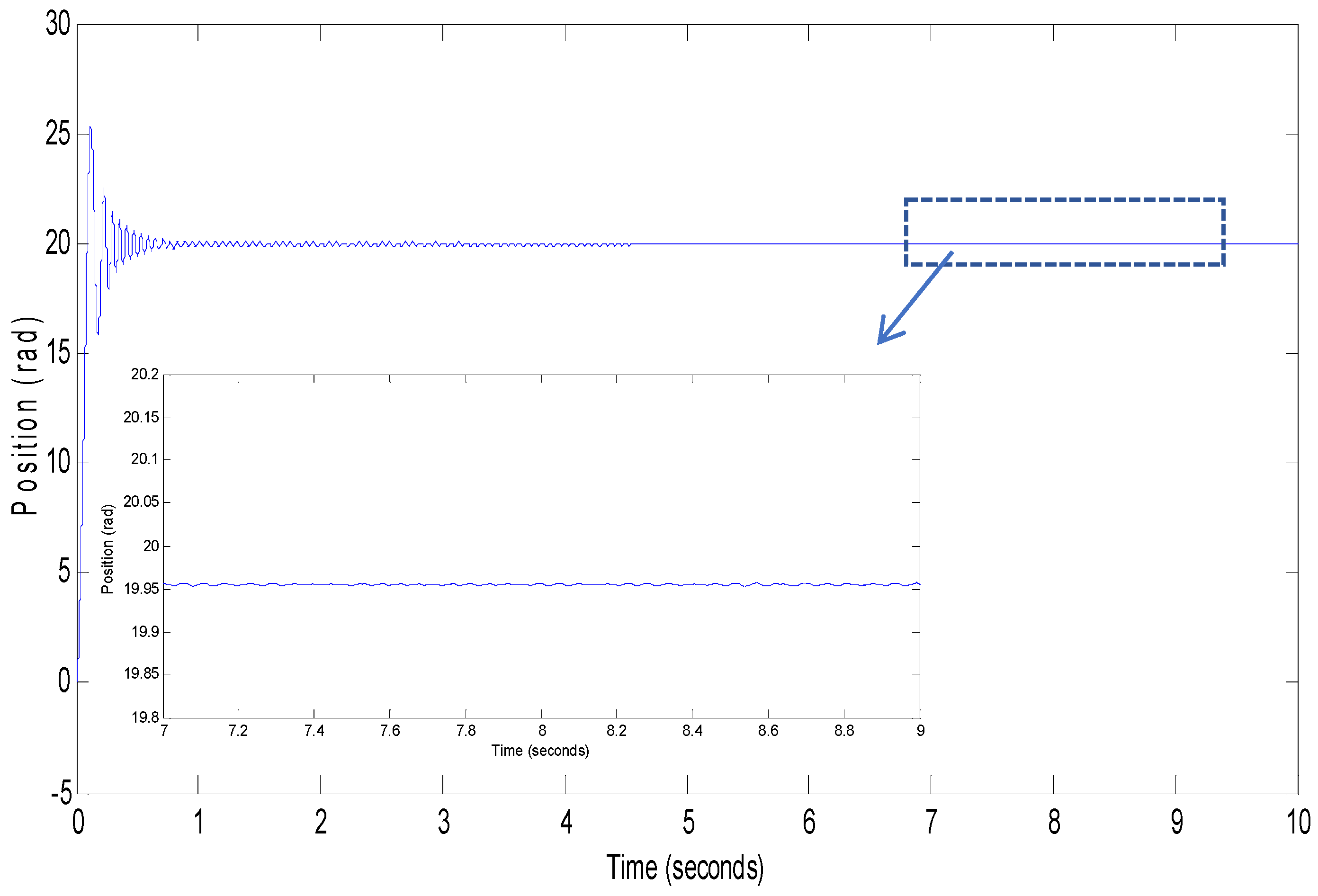
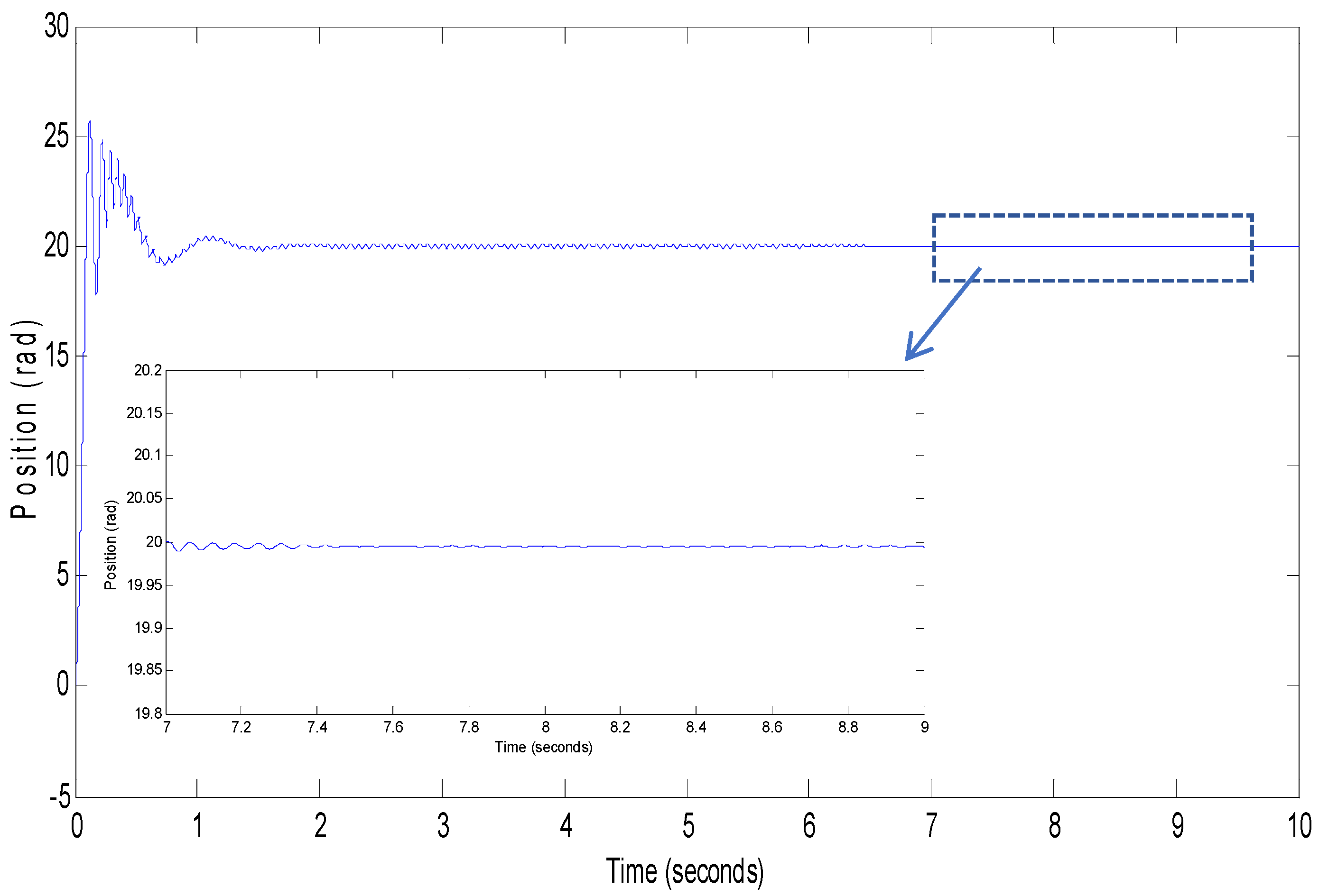
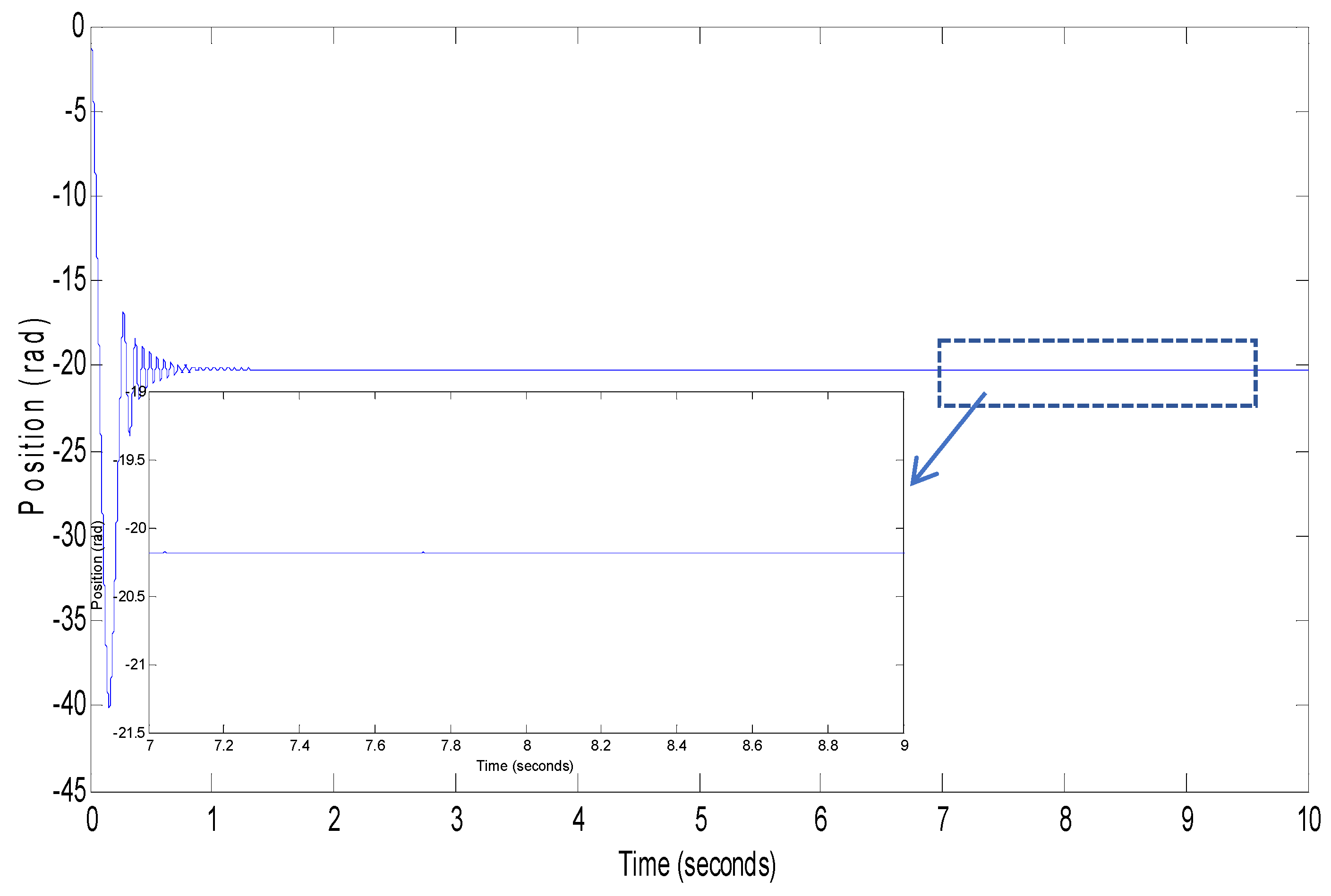
  • Case I: Comparison of steady-state responses for motor positions.
In this case study, we aim to compare the steady-state responses of PMSM positions across various systems. Our comparison intends to reveal the strengths and weaknesses inherent in each system, thereby offering invaluable insights to guide decision-making processes and enhance overall performance. Figure 2, Figure 3, Figure 4, Figure 5, Figure 6 and Figure 7 present a comparative analysis of the position responses of the PMSM when controlled by both the proposed and conventional controllers. To evaluate the control performance of different controllers, the reference position is set at 20 rad and −20 rad. Figure 2, Figure 3 and Figure 4 illustrate the position response curves under the differential SMC, double fractional-order differential SMC and STDFDSMC methods for various step signals with small load. Figure 5, Figure 6 and Figure 7 illustrate the position response curves under the differential SMC, double fractional-order differential SMC and STDFDSMC methods for various step signals with large load. The results clearly indicate that the STDFDSMC method, introduced in this paper, demonstrates the smallest steady-state error in comparison to other control techniques. To compare the steady-state errors under three different control methods, this paper conducts a comparison of the integrated square error (ISE) for the position response curves. The formula for the ISE is as follows:
I S E = y r y d t
As shown in Table 2, a detailed comparison of the position ISE among different control strategies is presented. The position response curves after reaching stability are selected for a comparison of their ISE. This comparison aims to evaluate and analyze the steady-state performance of each control method by quantifying the deviation between the actual position response and the desired position over a specified time interval.
From the enlarged Figure 2, Figure 3, Figure 4, Figure 5, Figure 6 and Figure 7 and Table 2, it can be clearly seen that the STDFDSMC method, which is introduced and detailed in this paper, exhibits the smallest steady-state error when compared to other control techniques that were evaluated in the same context. This demonstrates the superiority and effectiveness of the proposed STDFDSMC method in achieving more accurate and stable control performances.
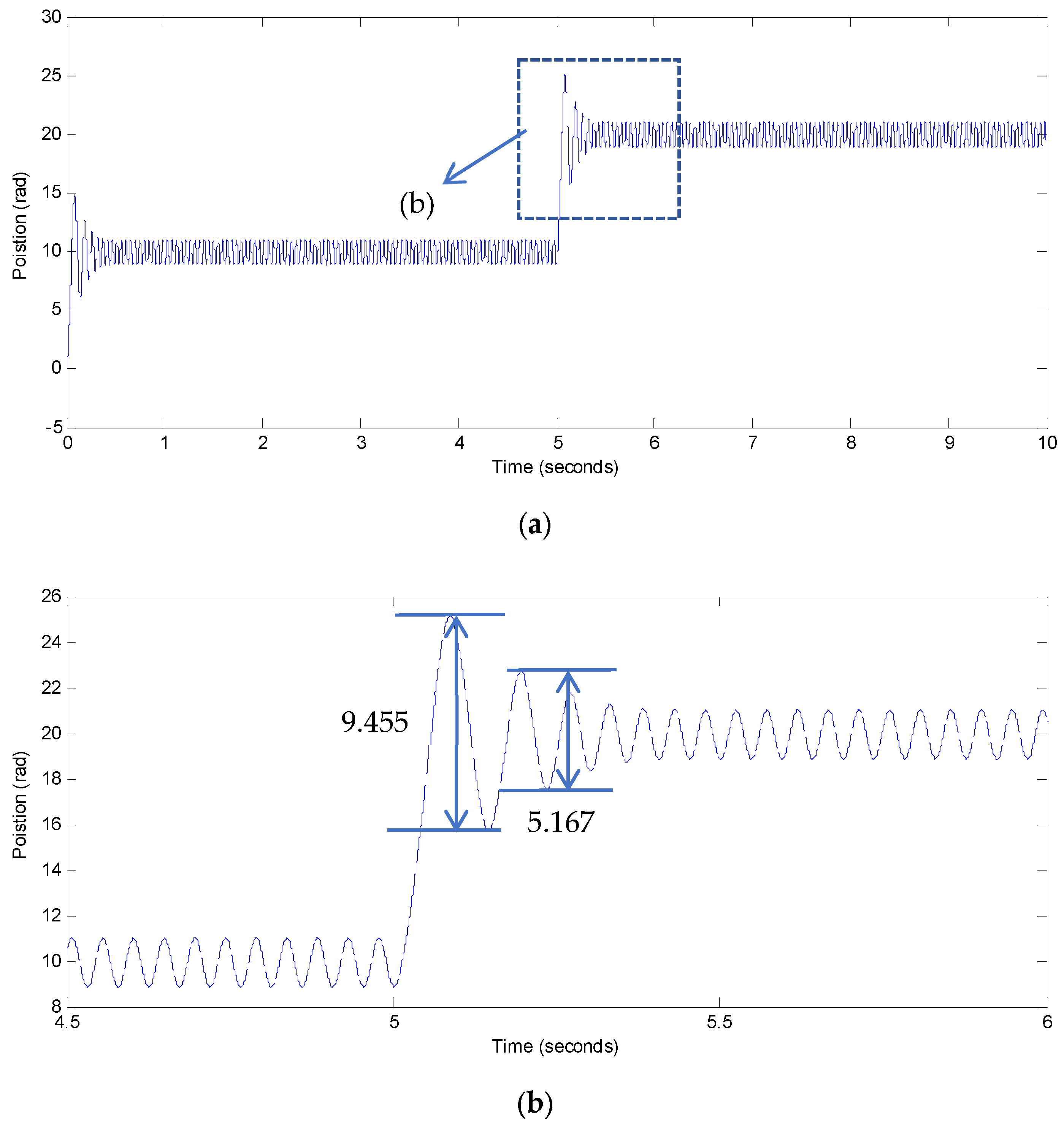
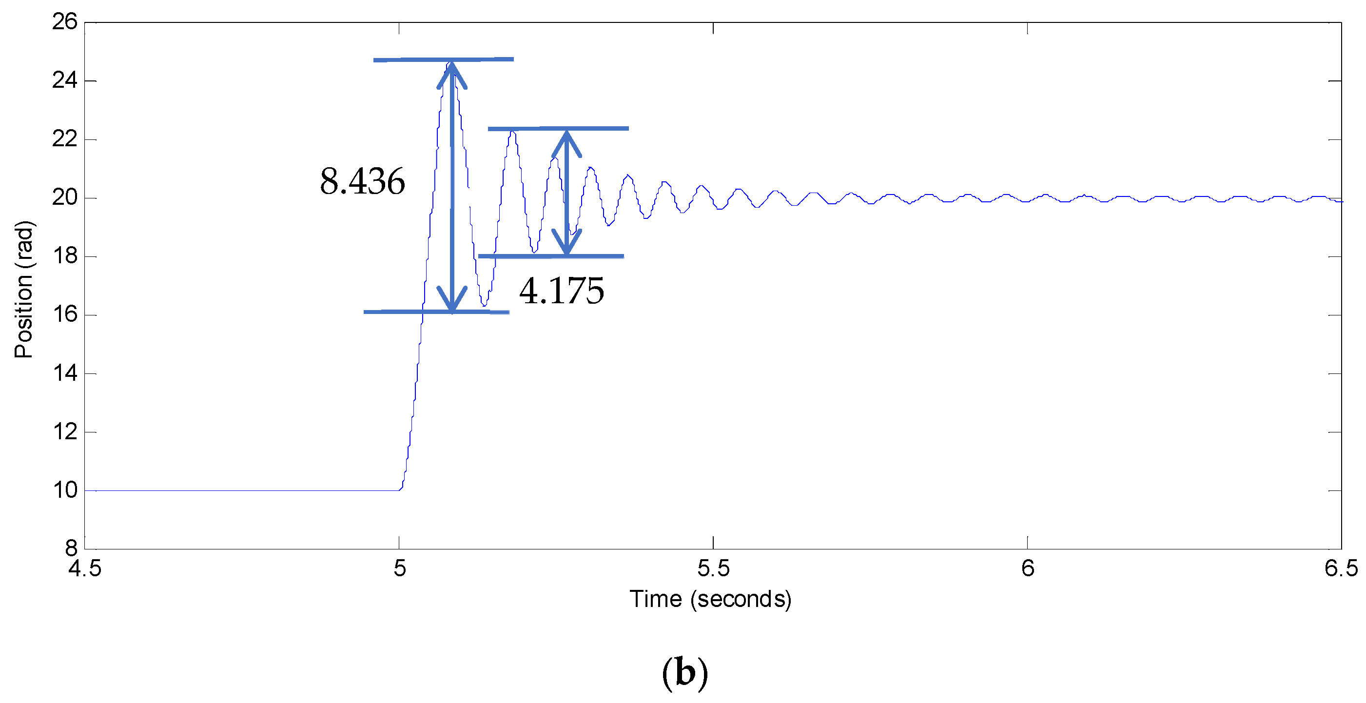
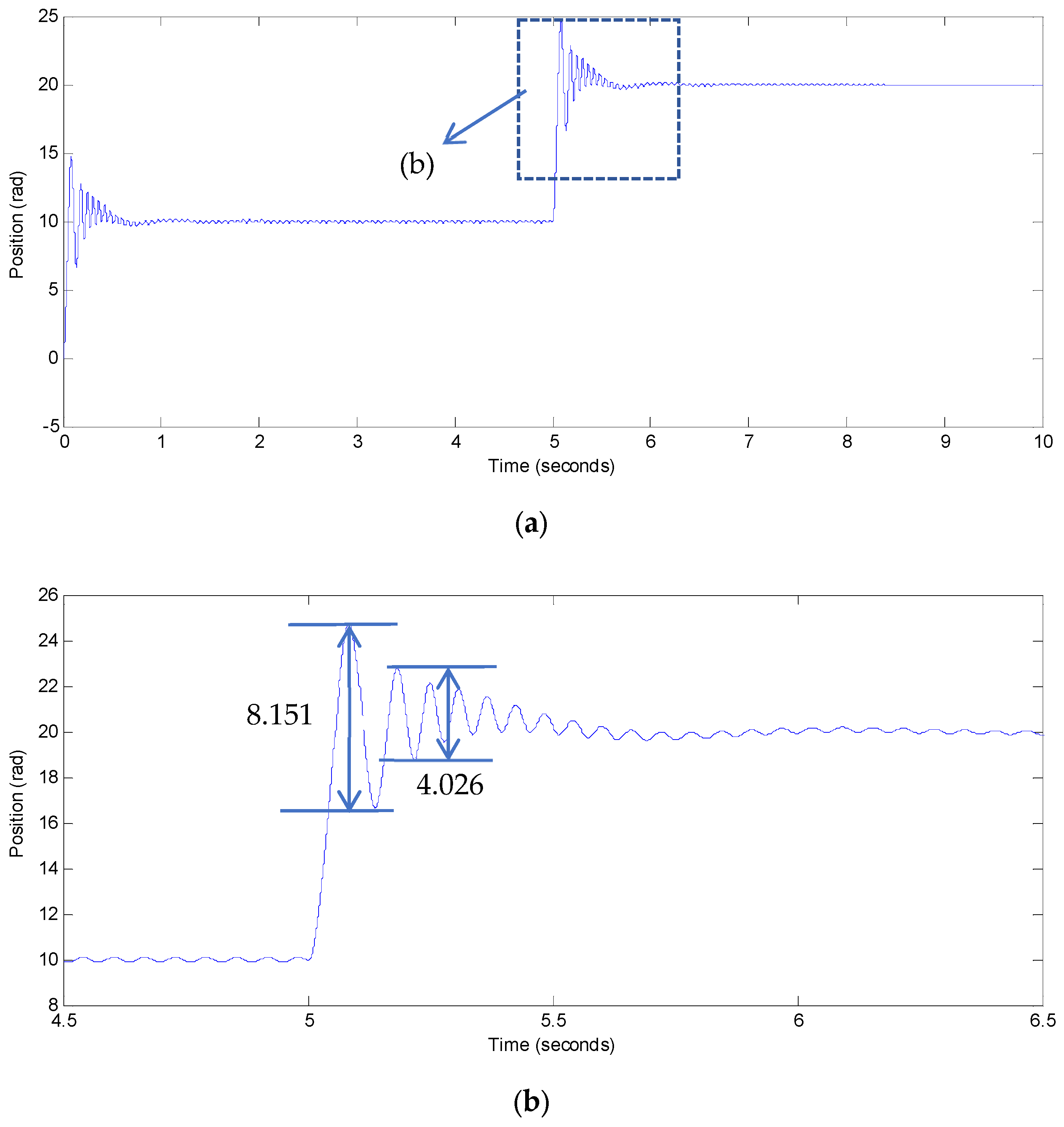
  • Case II: Comparison of dynamic responses for motor positions.
To illustrate the notable dynamic responses of motor positions in both non-composite control methods and the proposed composite control approach, we conducted a comparison of tracking abilities using a step signal under various controllers. The results of this test are presented in Figure 8, Figure 9 and Figure 10. Table 3 gives the comparative results of the sudden load change.
From Figure 8, Figure 9 and Figure 10 and Table 3, it can be seen that the position in the cases of the differential SMC, double fractional-order differential SMC, and STDFDSMC methods clearly state that the first fluctuation value of the positional response is 9.455 rad for differential SMC, 8.436 rad for double fractional-order differential SMC and 8.151 rad for STDFDSMC. The zoomed views of position in the cases of the differential SMC, double fractional-order differential SMC, and STDFDSMC methods clearly state that the second fluctuation value of the positional response is 5.167 rad for the differential SMC, 4.175 rad for the double fractional-order differential SMC and 4.026 rad for the STDFDSMC. Detailed analyses demonstrate that the tracking error for the reference signal is considerably lower in the proposed composite control method compared to the conventional composite control technique.
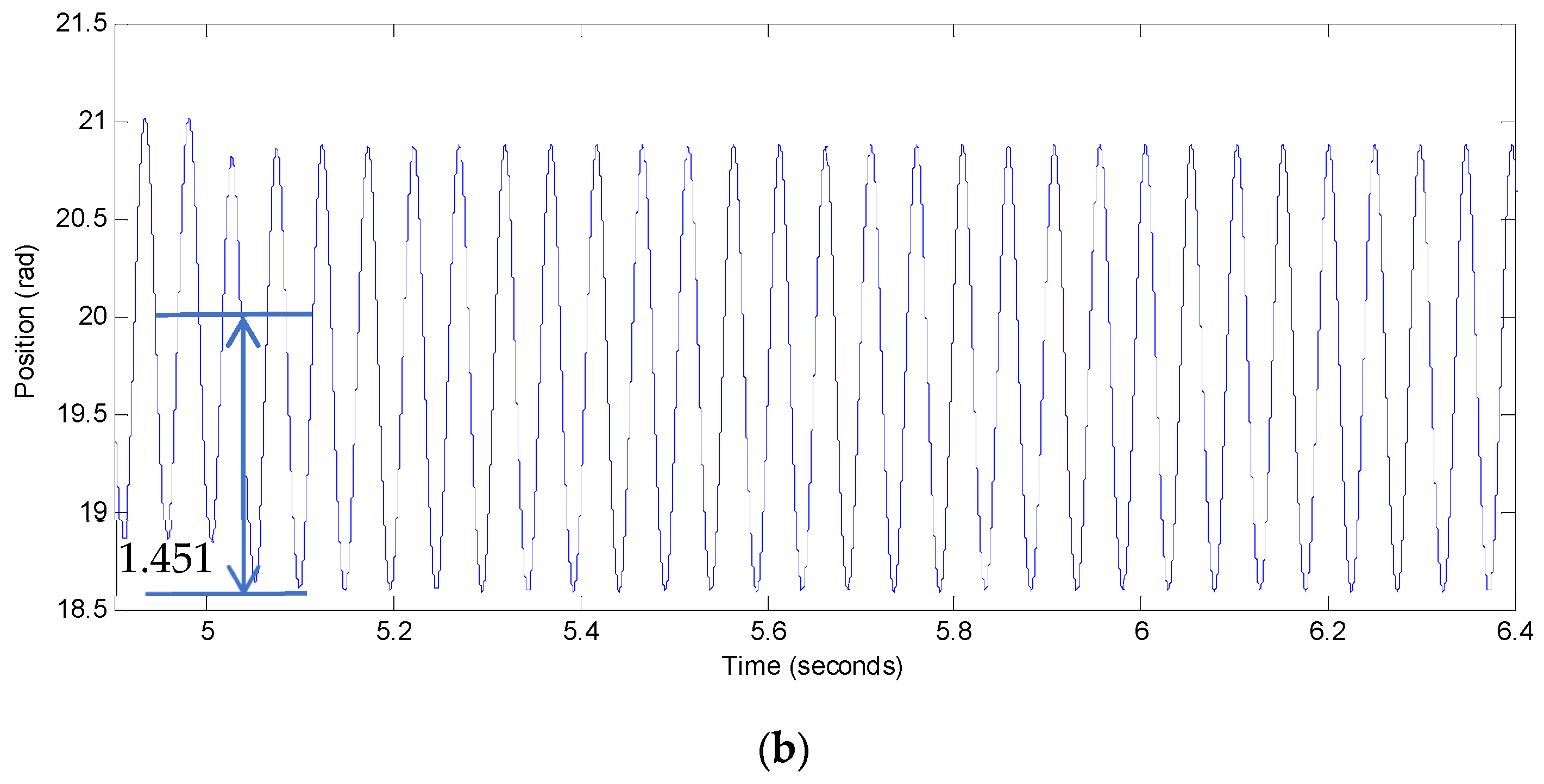
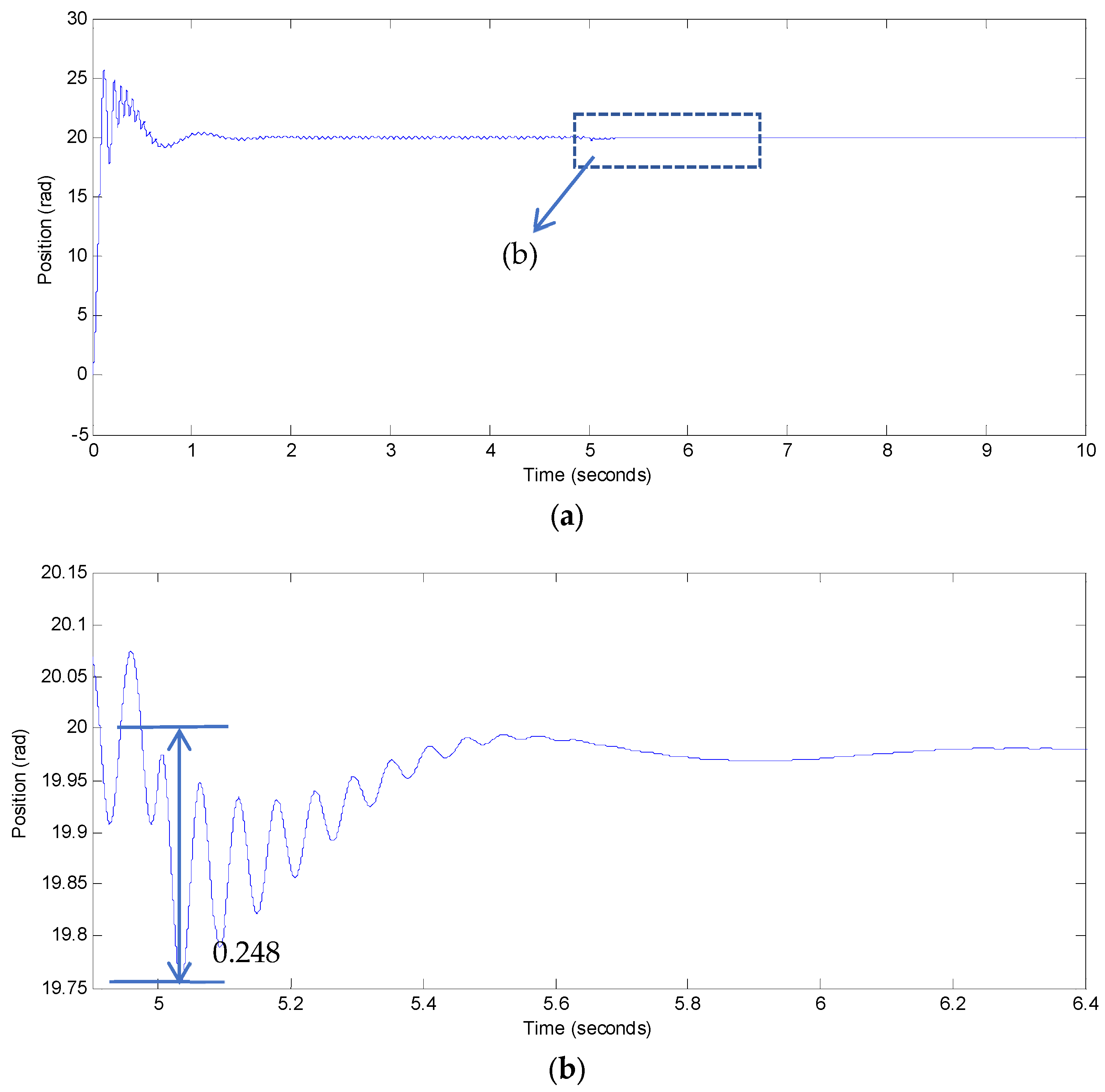
  • Case III: comparing resistance to external disturbances.
To assess the robustness of the proposed STDFDSMC method, we introduced a sudden change in external load during the simulation process. With the reference position fixed at 20 rad and a simulation time of 10 s, we observed the method’s response to this unexpected disturbance. In Figure 11, Figure 12 and Figure 13, the external load increased from 5 N m to 20 N m at 5 s under the differential SMC, double fractional-order differential SMC, and STDFDSMC methods, respectively. Figure 11, Figure 12 and Figure 13 demonstrate the influence of external load disturbances on various control strategies. As shown in Table 4, a detailed comparison of the resistance to external disturbances among different control strategies is presented. The zoomed views of position in the cases of the differential SMC, double fractional-order differential SMC, and STDFDSMC methods clearly state that the peak error value of position is 1.451 rad for differential SMC, 0.321 rad for double fractional-order differential SMC and 0.248 rad for STDFDSMC.
Notably, the overshoot value of position observed under the STDFDSMC method proved to be considerably smaller than that of the differential SMC and double fractional-order differential SMC methods. This finding underscores the exceptional robustness of the proposed STDFDSMC approach when compared to conventional control techniques.
In summary, the comparative results unequivocally demonstrate that the proposed STDFDSMC control method represents a significant advancement in optimizing the performance of PMSM drives, offering substantial improvements over existing control strategies. However, while the STDFDSMC exhibits promising outcomes in various control scenarios, it is essential to acknowledge its potential limitations and the specific conditions under which it may not perform at its best. Notably, the fractional-order components of the control strategy can be quite demanding in terms of computational resources. In environments with limited computational capabilities, the strategy may struggle to operate in real-time, leading to a decline in control performance. Furthermore, the effectiveness of the STDFDSMC is contingent upon precise sensor measurements and dependable actuator responses. Should sensors provide inaccurate readings or actuators fail to function as expected, the strategy may fall short of achieving the desired control objectives.

5. Conclusions and Future Work

This paper unveils a pioneering model-free fractional-order composite control method, meticulously crafted for the precise positioning of PMSM drives. This innovative approach elegantly fuses the STDFDSMC, creating a synergy that sets it apart. The hallmark of this method is a groundbreaking double fractional-order differential sliding mode surface, ingeniously designed to guarantee robust performance, exceptional flexibility, rapid convergence, and adept singularity prevention. Moreover, the CESO is skillfully utilized to provide accurate estimation of both internal and external disturbances. Looking ahead, we plan to conduct experimental validations to further substantiate our findings. Additionally, the integration of AI for adaptive control and real-time disturbance estimation promises to amplify its prowess, solidifying its position as a front-runner in the field of PMSM drive technology.

Author Contributions

This is a joint work and the authors were in charge of their expertise and capability: P.G. for investigation, analysis, and writing; C.Z., L.F. and H.P. for manuscript revision. All authors have read and agreed to the published version of the manuscript.

Funding

This research was funded by the National Natural Science Foundation of China (grant number 62103306), the Natural Science Foundation of Universities of Anhui Province (grant number 2024AH040228), the Talent Research Start-up Fund of Tongling University (grant number 2022tlxyrc33, grant number 2022tlxyrc34), Innovative Entrepreneurial Project for University Students in Anhui Province (grant number S202410383026).

Institutional Review Board Statement

Not applicable.

Informed Consent Statement

Not applicable.

Data Availability Statement

The original contributions presented in this study are included in the article. Further inquiries can be directed to the corresponding author.

Acknowledgments

The authors would like to express their gratitude to all those who helped them during the writing of this paper. The authors would like to thank the reviewers for their valuable comments and suggestions.

Conflicts of Interest

The authors declare no conflicts of interest.

References

  1. Tian, M.; Wang, T.; Yu, Y.; Dong, Q.; Wang, B.; Xue, D. Integrated observer-based terminal sliding-mode speed controller for PMSM drives considering multi-source disturbances. IEEE Trans. Power Electron. 2024, 39, 7968–7979. [Google Scholar] [CrossRef]
  2. Liu, X.; Deng, Y.; Liu, J.; Cao, H.; Xu, C.; Liu, Y. Fixed-time integral terminal sliding mode control with an adaptive RBF neural network for PMSM speed regulation. Control Eng. Pract. 2025, 156, 106236. [Google Scholar] [CrossRef]
  3. Pang, J.; Zhang, J.; Li, M.; Li, S. Time-varying command filters-based neural adaptive control with fixed-time prescribed performance for the PMSM with external disturbance and time delays. J. Franklin Inst. 2025, 362, 107527. [Google Scholar] [CrossRef]
  4. Jia, Z.; Song, W.; Ma, C.; Lu, T.; Huang, W. A generalized current residual-based diagnosis and classification method for interturn fault and high-resistance connection fault in model predictive controlled PMSMs. IEEE Trans. Power Electron. 2025, 40, 7239–7250. [Google Scholar] [CrossRef]
  5. Gao, P.; Zhang, G.; Ouyang, H.; Mei, L. An adaptive super twisting nonlinear fractional-order PID sliding mode control of permanent magnet synchronous motor speed regulation system based on extended state observer. IEEE Access 2020, 8, 53498–53510. [Google Scholar] [CrossRef]
  6. Gao, P.; Fang, L.; Pan, H. Complementary extended state observer-based model-free sliding mode control for a PMSM in cathode copper production. Electron. Lett. 2024, 60, e70044. [Google Scholar] [CrossRef]
  7. Tang, B.; Lu, W.; Yan, B.; Lu, K.; Feng, J.; Guo, L. A novel position speed integrated sliding mode variable structure controller for position control of PMSM. IEEE Trans. Ind. Electron. 2021, 69, 12621–12631. [Google Scholar] [CrossRef]
  8. Ruan, G.; Su, Y.; Cao, J.; Su, Y.; Gong, Z.; Hu, X. Position tracking control of permanent magnet synchronous motor based on AHONFTSMC control. J. Electr. Eng. Technol. 2024, 20, 389–401. [Google Scholar] [CrossRef]
  9. Zhang, W.; Cao, B.; Nan, N.; Li, M.; Chen, Y. An adaptive PID-type sliding mode learning compensation of torque ripple in PMSM position servo systems towards energy efficiency. ISA Trans. 2021, 110, 258–270. [Google Scholar] [CrossRef]
  10. Hu, J.; He, C.; Li, Y. A novel predictive position control with current and speed limits for PMSM drives based on weighting factors elimination. IEEE Trans. Ind. Electron. 2022, 69, 12458–12468. [Google Scholar] [CrossRef]
  11. Xu, X.; Lu, S.; Jiang, Y.; Liu, J.; Zhang, L. Driving strategy of unmanned ground vehicle under split-docking road conditions based on improved EKF and PID-modified SMC. Adv. Eng. Inform. 2024, 62, 102830. [Google Scholar] [CrossRef]
  12. Xiao, H.; Zhen, Z.; Xue, Y. Fault-tolerant attitude tracking control for carrier-based aircraft using RBFNN-based adaptive second-order sliding mode control. Aerosp. Sci. Technol. 2023, 139, 108408. [Google Scholar] [CrossRef]
  13. Abdelaal, A.K.; Shaheen, A.M.; El-Fergany, A.A.; Alqahtani, M.H. Sliding mode control based dynamic voltage restorer for voltage sag compensation. Results Eng. 2024, 24, 102936.2. [Google Scholar] [CrossRef]
  14. Shevidi, A.; Hashim, H.A. Quaternion-based adaptive backstepping fast terminal sliding mode control for quadrotor UAVs with finite time convergence. Results Eng. 2024, 23, 102497. [Google Scholar] [CrossRef]
  15. Truong, T.N.; Vo, A.T.; Kang, H. A model-free terminal sliding mode control for robots: Achieving fixed-time prescribed performance and convergence. ISA Trans. 2024, 144, 330–341. [Google Scholar] [CrossRef]
  16. Safari, A.; Sorouri, H.; Oshnoei, A. The regulation of superconducting magnetic energy storages with a neural-tuned fractional order PID controller based on brain emotional learning. Fractal Fract. 2024, 8, 365. [Google Scholar] [CrossRef]
  17. Shiryayeva, O.; Suleimenov, B.; Kulakova, Y. Optimal design of I-PD and PI-D industrial controllers based on artificial intelligence algorithm. Algorithms 2024, 17, 288. [Google Scholar] [CrossRef]
  18. Sahin, A.K.; Cavdar, B.; Ayas, M.S. An adaptive fractional controller design for automatic voltage regulator system: Sigmoid-based fractional-order PID controller. Neural Comput. Appl. 2024, 36, 14409–14431. [Google Scholar] [CrossRef]
  19. Tumari, M.Z.M.; Ahmad, M.A.; Suid, M.H.; Ghazali, M.R.; Tokhi, M.O. An improved marine predators algorithm tuned data-driven multiple-node hormone regulation neuroendocrine-PID controller for multi-input–multi-output gantry crane system. J. Low Freq. Noise Vib. Act. Control 2023, 42, 1666–1698. [Google Scholar] [CrossRef]
  20. Elgezouli, D.E.; Eltayeb, H.; Abdoon, M.A. Novel GPID: Grünwald–Letnikov fractional PID for enhanced adaptive cruise control. Fractal Fract. 2024, 8, 751. [Google Scholar] [CrossRef]
  21. Wang, Y.; Lu, X.; Gao, Y.; Chen, Y. An anti-swing control method combining deep learning prediction models with a multistate fractional-order terminal sliding mode controller for wave motion compensation devices. Mech. Syst. Signal Process. 2025, 223, 111819. [Google Scholar] [CrossRef]
  22. Singh, A.P.; Bingi, K. Applications of fractional-order calculus in robotics. Fractal Fract. 2024, 8, 403. [Google Scholar] [CrossRef]
  23. Gao, P.; Fang, L.; Pan, H. Interdisciplinary education promotes scientific research innovation: Take the composite control of the permanent magnet synchronous motor as an example. Mathematics 2024, 12, 2602. [Google Scholar] [CrossRef]
  24. Mseddi, A.; Abid, A.; Naifar, O.; Rhaima, M.; Makhlouf, A.B.; Mchiri, L. Investigation of the robust fractional order control approach associated with the online analytic unity magnitude shaper: The case of wind energy systems. Fractal Fract. 2024, 8, 187. [Google Scholar] [CrossRef]
  25. Tumari, M.Z.M.; Ahmad, M.A.; Rashid, M.I.M. A fractional order PID tuning tool for automatic voltage regulator using marine predators algorithm. Energy Rep. 2023, 9, 416–421. [Google Scholar] [CrossRef]
  26. Sharma, R.; Rana, K.P.S.; Kumar, V. Performance analysis of fractional order fuzzy PID controllers applied to a robotic manipulator. Expert Syst. Appl. 2014, 41, 4274–4289. [Google Scholar] [CrossRef]
  27. Li, H.; Cao, J.; Hu, C.; Jiang, H.; Alsaedi, A. Synchronization analysis of nabla fractional-order fuzzy neural networks with time delays via nonlinear feedback control. Fuzzy Sets Syst. 2024, 475, 108750. [Google Scholar] [CrossRef]
  28. Hua, X.; Wong, P.K.; Zhao, J.; Xie, Z. Adaptive fractional-order nonsingular terminal sliding mode control and sequential quadratic programming torque distribution for lateral stability of FWID-EVs with actuator constraints. ISA Trans. 2024, 150, 208–222. [Google Scholar] [CrossRef]
  29. Pan, J. Fractional-order sliding mode control of manipulator combined with disturbance and state observer. Robot. Auton. Syst. 2025, 183, 104840. [Google Scholar] [CrossRef]
  30. Sheng, Y.; Gan, J.; Guo, X. Predefined-time fractional-order time-varying sliding mode control for arbitrary order systems with uncertain disturbances. ISA Trans. 2024, 146, 236–248. [Google Scholar] [CrossRef]
  31. Li, S.; Lu, H.; Li, J.; Zheng, T.; He, Y. Fractional-order sliding mode controller based on ESO for a buck converter with mismatched disturbances: Design and experiments. IEEE Trans. Ind. Electron. 2025; in press. [Google Scholar]
  32. Memarzade, S.; Zarif, M.H.; Alfi, A. Observer-based fractional-order dynamic terminal sliding mode control of active shock absorbing prostheses for lower limb amputees. ISA Trans. 2025; in press. [Google Scholar]
  33. Zhang, Z.; Zhang, H. Fractional-order sliding mode with active disturbance rejection control for UAVs. Appl. Sci. 2025, 15, 556. [Google Scholar] [CrossRef]
  34. Ullah, S.; Alsafran, A.; Harrison, A.; Hafeez, G.; Hassan, A.; Alghamdi, B.; Kraiem, H. A uniform robust exact differentiator based neuro-fuzzy fractional order sliding mode control for optimal standalone solar photovoltaic system. IEEE Access 2025, 13, 4411–4423. [Google Scholar] [CrossRef]
  35. Xu, Y.; Kang, S.; Li, T.; Liu, G. Finite-time fractional-order sliding mode force control with time delay estimation and RBFNN compensation: Design and application to cell microinjection. J. Franklin Inst. 2025, 362, 107470. [Google Scholar] [CrossRef]
  36. Han, J. From PID to active disturbance rejection control. IEEE Trans. Ind. Electron. 2009, 56, 900–906. [Google Scholar] [CrossRef]
  37. Wang, S.; Gan, H.; Luo, Y.; Wang, X.; Gao, Z. Active disturbance rejection control with fractional-order model-aided extended state observer. ISA Trans. 2023, 142, 527–537. [Google Scholar] [CrossRef]
  38. Sun, X.; Lin, X.; Guo, D.; Lei, G.; Yao, M. Improved deadbeat predictive current control with extended state observer for dual three-phase PMSMs. IEEE Trans. Power Electron. 2024, 39, 6769–6782. [Google Scholar] [CrossRef]
  39. Ran, M.; Li, J.; Xie, L. A new extended state observer for uncertain nonlinear systems. Automatica 2021, 131, 109772. [Google Scholar] [CrossRef]
  40. Hua, X.; Huang, D.; Guo, S. Extended state observer based on ADRC of linear system with incipient fault. Int. J. Control Autom. Syst. 2020, 18, 1425–1434. [Google Scholar] [CrossRef]
  41. Lyu, S.; Lang, X.; Wang, D. Koopman-based robust learning control with extended state observer. IEEE Robot. Autom. Lett. 2025, 10, 2303–2310. [Google Scholar] [CrossRef]
  42. Li, Y.; Hu, Y.; Wu, W. Complex-coefficient adaptive extended state observer for position estimation of PMSMs with enhanced robustness to disturbances. IEEE J. Emerg. Sel. Top. Power Electron. 2025; in press. [Google Scholar]
  43. Chen, Y.; Zhang, J.; Zhang, L. Fixed-time sliding mode trajectory tracking control for uncertain robotic manipulators using high-order extended state observer. Trans. Inst. Meas. Control, 2025; in press. [Google Scholar]
  44. Zhao, J.; Wang, G.; Zhang, G.; Hao, Y.; Zhao, N.; Hu, Z.; Zhu, L.; Xu, D. Extended flux projection vector observer based position error compensation strategy for sensorless direct torque controlled PMSM drives. IEEE Trans. Power Electron. 2025; in press. [Google Scholar]
  45. Hong, J.; Lin, X.; Zhang, J.; Xu, Y.; Yan, B.; Li, X. A state feedback control with compensation for permanent magnet synchronous machine drives. ISA Trans. 2024, 150, 232–242. [Google Scholar] [CrossRef]
  46. Wang, L.; Liu, G.; Xu, C. An improved nonlinear active disturbance rejection controller via sine function and whale optimization algorithm for permanent magnet synchronous motors speed control. IEEJ Trans. Electr. Electron. Eng. 2024; in press. [Google Scholar]
  47. Guan, W.; Cheng, Y.; Luo, G.; Dou, M. Research on non-linear active disturbance rejection speed synchronisation control of aviation dual motor actuator considering current saturation constraints. IET Electr. Power Appl. 2024, 18, 1796–1806. [Google Scholar] [CrossRef]
  48. Guo, Z.; Li, J.; Yan, M.; Wang, G. Composite speed control based on an improved gain-adaptive super-twisting sliding mode observer for a permanent magnet synchronous motor. Control Eng. Pract. 2025, 157, 106241. [Google Scholar] [CrossRef]
  49. Zhao, K.; Liu, W.; Zhou, R.; Dai, W.; Wu, S.; Qiu, P.; Yin, Y.; Jia, N.; Yi, J.; Huang, G. Model-free fast integral terminal sliding-mode control method based on improved fast terminal sliding-mode observer for PMSM with unknown disturbances. ISA Trans. 2023, 143, 572–581. [Google Scholar] [CrossRef]
  50. Hou, Q.; Ding, S.; Yu, X.; Mei, K. A super-twisting-like fractional controller for SPMSM drive system. IEEE Trans. Ind. Electron. 2021, 69, 9376–9384. [Google Scholar] [CrossRef]
  51. Li, S.; Zhou, M.; Yu, X. Design and implementation of terminal sliding mode control method for PMSM speed regulation system. IEEE Trans. Ind. Inform. 2012, 9, 1879–1891. [Google Scholar] [CrossRef]
  52. Zheng, C.; Zhang, J. Finite-time nonlinear disturbance observer based discretized integral sliding mode control for PMSM drives. J. Power Electron. 2018, 18, 1075–1085. [Google Scholar]
  53. Zhang, Z.; Liu, X.; Yu, J.; Yu, H. Time-varying disturbance observer based improved sliding mode single-loop control of PMSM drives with a hybrid reaching law. IEEE Trans. Energy Convers. 2023, 38, 2539–2549. [Google Scholar] [CrossRef]
  54. Li, C.; Deng, W. Remarks on fractional derivatives. Appl. Math. Comput. 2007, 187, 777–784. [Google Scholar] [CrossRef]
  55. Qian, D.; Li, C.; Agarwal, R.P.; Wong, P.J.Y. Stability analysis of fractional differential system with Riemann-Liouville derivative. Math. Comput. Modell. 2010, 52, 862–874. [Google Scholar] [CrossRef]
  56. Li, W.; Yuan, H.; Li, S.; Zhu, J. A revisit to model-free control. IEEE Trans. Power Electron. 2022, 37, 14408–14421. [Google Scholar] [CrossRef]
  57. Fliess, M.; Join, C. Model-free control. Int. J. Control 2013, 86, 2228–2252. [Google Scholar] [CrossRef]
  58. Fliess, M.; Cédric, J. Intelligent PID controllers. In Proceedings of the 2008 16th Mediterranean Conference on Control and Automation, Ajaccio, France, 25–27 June 2008. [Google Scholar]
  59. El-Sousy, F.F.M. Optimal adaptive ultra-local model-free control based on extended state observer for PMSM driven single-axis servo mechanism system. IEEE Trans. Ind. App. 2024, 60, 7728–7745. [Google Scholar] [CrossRef]
  60. Zhao, L.; Dai, L.; Xia, Y.; Li, P. Attitude control for quadrotors subjected to wind disturbances via active disturbance rejection control and integral sliding mode control. Mech. Syst. Signal Process. 2019, 129, 531–545. [Google Scholar] [CrossRef]
  61. Khan, R.F.A.; Rsetam, K.; Cao, Z.; Man, Z. Singular perturbation-based adaptive integral sliding mode control for flexible joint robots. IEEE Trans. Ind. Electron. 2022, 70, 10516–10525. [Google Scholar] [CrossRef]
  62. Moreno, J.A.; Osorio, M. Strict Lyapunov functions for the super-twisting algorithm. IEEE Trans. Autom. Control 2012, 57, 1035–1040. [Google Scholar] [CrossRef]
  63. Wang, H.; Chen, X.; Zhao, X.; Dan, H.; Su, M.; Sun, Y. A cascade PI-SMC method for matrix converter-fed BDFIM drives. IEEE Trans. Transp. Electrific. 2021, 7, 2541–2550. [Google Scholar] [CrossRef]
  64. Gao, P.; Zhang, G.; Lv, X. Model-free control using improved smoothing extended state observer and super-twisting nonlinear sliding mode control for PMSM drives. Energies 2021, 14, 922. [Google Scholar] [CrossRef]
  65. Gu, J.; You, S.; Kim, W.; Moon, J. Fuzzy event-triggered super twisting sliding mode control for position tracking of permanent magnet synchronous motors under unknown disturbances. IEEE Trans. Ind. Inform. 2023, 19, 9843–9854. [Google Scholar] [CrossRef]
  66. Gao, P.; Pan, H. Model-free double fractional-order integral sliding mode control for permanent magnet synchronous motor based electric mopeds drive system. IEICE Electron. Express 2023, 20, 20230178. [Google Scholar] [CrossRef]
  67. Li, H.; Yang, S.; Kong, L.; Wen, T. High-precision angular speed tracking control of gimbal system with harmonic reducer. IEEE Trans. Ind. Electron. 2021, 69, 8168–8177. [Google Scholar] [CrossRef]
  68. Jung, T.-U.; Jang, J.-H.; Park, C.-S. A back-EMF estimation error compensation method for accurate rotor position estimation of surface mounted permanent magnet synchronous motors. Energies 2017, 10, 1160. [Google Scholar] [CrossRef]
  69. Li, H.; Song, B.; Chen, T.; Xie, Y.; Zhou, X. Adaptive fuzzy PI controller for permanent magnet synchronous motor drive based on predictive functional control. J. Franklin Inst. 2021, 358, 7333–7364. [Google Scholar] [CrossRef]
  70. Liu, G.; Fang, L.; Liu, Z.; Chen, Q.; Zhang, J. Active disturbance rejection control of a magnetic screw motor for high tracking performance. IEEE Trans. Power Electron. 2022, 37, 9641–9651. [Google Scholar] [CrossRef]
  71. Xu, D.; Yao, H.; He, Y.; Zhao, W. Current loop disturbance suppression for dual three phase permanent magnet synchronous generators based on modified linear active disturbance rejection control. Chin. J. Electr. Eng. 2023, 10, 101–113. [Google Scholar] [CrossRef]
Figure 1. (a) The field oriented control of the PMSM control system; (b) The detailed block diagram of the proposed STDFDSMC.
Fractalfract 09 00161 g001aFractalfract 09 00161 g001b
Figure 2. Position response curve of PMSM under the traditional differential SMC with small load.
Fractalfract 09 00161 g002
Figure 3. Position response curve of PMSM under the double fractional-order differential SMC with small load.
Fractalfract 09 00161 g003
Figure 4. Position response curve of PMSM under the proposed STDFDSMC with small load.
Fractalfract 09 00161 g004
Figure 5. Position response curve of PMSM under the traditional differential SMC with large load.
Fractalfract 09 00161 g005
Figure 6. Position response curve of PMSM under the double fractional-order differential SMC with large load.
Fractalfract 09 00161 g006
Figure 7. Position response curve of PMSM under the proposed STDFDSMC with large load.
Fractalfract 09 00161 g007
Figure 8. (a) Position response curve of PMSM under the traditional differential SMC with step signal; (b) Detailed view of the image (a).
Fractalfract 09 00161 g008
Figure 9. (a) Position response curve of PMSM under the double fractional-order differential SMC with step signal; (b) Detailed view of the image (a).
Fractalfract 09 00161 g009aFractalfract 09 00161 g009b
Figure 10. (a) Position response curve of PMSM under the proposed STDFDSMC with step signal; (b) Detailed view of the image (a).
Fractalfract 09 00161 g010
Figure 11. (a) Position response curve rejecting external disturbance under the traditional differential SMC; (b) Detailed view of the image (a).
Fractalfract 09 00161 g011aFractalfract 09 00161 g011b
Figure 12. Position response curve rejecting external disturbance under the double fractional-order differential SMC; (b) Detailed view of the image (a).
Fractalfract 09 00161 g012
Figure 13. (a) Position response curve rejecting external disturbance under the proposed STDFDSMC; (b) Detailed view of the image (a).
Fractalfract 09 00161 g013
Table 1. Summary of the advantages of the STDFDSMC over the other control scheme.
Control StrategiesIssue
Dynamic ResponseSteady-State Response Robustness
The other control scheme (Like differential SMC, double fractional-order differential SMC)Less effectiveLess effectiveLess effective
STDFDSMCBetterBetterBetter
Table 2. The comparative results of the ISE during steady-state operation.
Control StrategiesISE
20 Rad−20 Rad
Differential SMC 1.75952.2366
Double fractional-order differential SMC 0.02310.0992
STDFDSMC0.00130.0076
Table 3. The comparison results of dynamic responses.
Control StrategiesRise Time (s)First Fluctuation Value of the Positional Response (Rad)Second Fluctuation Value of the Positional Response (Rad)
Differential SMC 0.0529.4555.167
Double fractional-order differential SMC 0.0478.4364.175
STDFDSMC0.0458.1514.026
Table 4. The comparative results of the load changed suddenly.
Control StrategiesOvershoot Value of Position When the External Load Sudden Increase (Rad)
Differential SMC 1.451
Double fractional-order differential SMC 0.321
STDFDSMC0.248
Disclaimer/Publisher’s Note: The statements, opinions and data contained in all publications are solely those of the individual author(s) and contributor(s) and not of MDPI and/or the editor(s). MDPI and/or the editor(s) disclaim responsibility for any injury to people or property resulting from any ideas, methods, instructions or products referred to in the content.

