1. Introduction
The expanding structure, complexity, and increasing scale of contemporary low-carbon power networks have made the frequency stability problem more inherent in representing the equilibrium between power generation and demand, where one of the biggest difficulties in running contemporary energy systems is preserving the power balance between generation and consumption. Therefore, an imbalance between the power supply and demand would result in tie-line power mismatching among interconnected locations and system frequency deviation [
1,
2]. Incorporating renewable energy sources (RESs) into the distributed use system is now feasible with microgrids (MGs), a novel paradigm for small-scale power systems. Energy storage systems (ESSs), local loads, and a variety of RESs of distributed generation are usually included in MGs, which are considered a controllable entity in the power system that may be handled in either standalone or grid-tied modes [
3]. To reduce greenhouse gas emissions, there has been a significant push recently to include RESs in current power systems as a viable substitute and essential component of conventional power plants. As a result, RES generators are replacing synchronous generators (SGs), which are the primary origin of dynamics in conventional power networks. In contrast to conventional power systems with SGs, new power networks with RESs have little to no inertia.
The corresponding inertia factor approximately vanishes in RESs, as most of them lack a spinning mass that provides the power system with the inertia attribute [
4]. Additionally, the grid does not obtain inertia from the power electronic converters necessary to incorporate RESs like wind and photovoltaic (PV) systems [
5]. Therefore, frequency and voltage instability result from the contemporary power system’s decreasing inertia as RES penetration increases. Additionally, given the erratic and unpredictable nature of RES power generation, a large-scale integration of RESs into the grid will significantly raise the need for frequency control [
6]. On the other hand, even at small imbalance magnitudes that may cause cascading outages and generator tripping, the power system’s rate of change of frequency (RoCoF) would be high enough to trigger the load-shedding protection relays because of the decrease in inertia [
7]. Compared to previous power grids, contemporary power grids are therefore more susceptible to disturbances such as short circuit failures, abrupt changes in demand, critical frequency oscillations, and involuntary islanding occurrences. The stability, robustness, and efficiency of contemporary low-inertia energy systems will thus face a new challenge. Consequently, the reduction in power system inertia is the primary barrier to the deployment of RESs in contemporary linked power networks [
8].
Increasing the inertia significantly to offset the decline in system inertia is one method of stabilizing the voltage and frequency of modern microgrids. Virtual synchronous generator (VSG) or virtual inertia control (VIC) are terms used to describe this phenomenon of virtual inertia [
9]. The VIC concept may be developed in modern power systems using an inverter-based energy storage system (ESS) and the proper control technique. Among the greatest VIC approaches for enhancing the frequency stability of advanced microgrids is the derivative control method, which produces virtual inertia. Additionally, the derivative control process is paired with the proportional-integral (PI) controller in the framework of the VIC system, and the H∞ approach has been suggested for the improvement of frequency stability of modern energy systems with substantial RES penetration [
10].
Numerous studies have been undertaken to address these problems. The authors of [
11] described an impedance-matching control-based inertia support system. It calculates the various control parameter coefficients but does not use system strength to assess the overall performance of the system. This limitation limits the application of the suggested method in weaker grids, where control and stability effectiveness are greatly impacted by microgrid strength. A virtual oscillator regulator is used in [
12] to describe an Agri forming control method that minimizes grid frequency variation by controlling the inverter output. The control system’s lack of an inertia impact on system stability is the main disadvantage of that technique. The synchronization of inertia and damping effect during high penetration of RESs supports research on battery ESSs (BESSs), which was published in [
13]. Nevertheless, it needs to be addressed that the research does not confirm across wide variations in parameters via different RES scenarios. In [
14], tiny signal analysis is used to create the related block diagram and control relations of the traditional voltage sag control technique. They cover overall system stability and in-depth parameter computations. Microgrids have low power quality and frequency instability as a result of disturbances that cause the standard droop management method to fail, owing to fast main frequency shifts and higher frequency oscillations. The virtual inertia-based approach offers flexibility in controlling power oscillations, and the swing equations were utilized in [
5] to adjust the different controller settings in real time. Higher inertia decreases the power suppression rush, but less significant virtual inertia encourages raising the deceleration stage [
15]. Although several studies acknowledge the trade-off, more research is required to design a VSG controller that integrates a combined analysis of dynamic reactions. Particularly in weak grids when the system’s capacity to control voltage and frequency fluctuations is greatly diminished, certain VIC approaches could not function as well as others [
16,
17]. These tactics are intended to maintain stability in a range of grid conditions. By taking into consideration the frequency variation with virtual inertia, the authors of [
18] presented an adaptive method for altering the virtual mass of the virtual inertia. By using this approach, the utility system becomes more resilient to overloads and disturbances. An optimal control technique has been proposed in [
19] to decrease dynamic oscillations, improve frequency stability, and speed up the dynamic response of the system within specific damping and inertia ranges. This has to do with controlling the voltage and frequency of a power system. Although the system is robust, its overall adoption is difficult due to its need for high-quality data. To manage excessive grid disruptions caused by the excessive penetration of RESs into microgrids, a reliable control process employing VSG is established in [
20]. The overall result demonstrates the effectiveness of the suggested method, despite the fact that the entire strategy is difficult to implement. In order to enhance the power-sharing, voltage, and dynamic frequency capabilities across AC/DC sub-grids, the authors of a work [
21] introduced a VSG-based DC/AC hybrid microgrid control technique using an interlinking converter. The performance of the microgrid under different load variations has not been investigated, even though the technology can increase microgrid stability generally. In [
22], a hierarchical deep learning-based microgrid control approach is introduced to enhance voltage and frequency stability. Overall performance is improved by a dual-layer control technique that permits accurate frequency and voltage adjustment.
Several recent studies (2023–2025) have investigated enhanced Virtual Inertia–Damping Control (VIDC) and synthetic inertia frameworks [
23,
24,
25,
26,
27]. However, most of these studies were developed and validated without incorporating the emulation of primary and secondary frequency control loops, which limits their ability to represent the complete dynamic behavior of a conventional SG. To address this limitation and enhance the frequency stability of low-inertia, renewable-dominated power systems, this research proposes a developed VIDC technique that integrates fractional-order control theory into both the virtual primary and secondary control loops (FO-VPSC). The proposed approach is further coordinated with a Battery Energy Storage System (BESS)-based VIDC to provide greater flexibility in mitigating a wide range of system disturbances. The Dandelion Optimizer (DO) algorithm is employed to optimally tune the FO-VPSC parameters, ensuring robustness and adaptability under varying operating conditions. The effectiveness of the proposed strategy is validated on a two-area interconnected renewable power system comprising diverse generation sources, including a thermal power plant, solar and wind units, and BESSs—consistent with the benchmark model presented in [
15]. Simulation results demonstrate that the FO-VPSC-based VIDC significantly enhances dynamic frequency support by generating an additional active-power command through fractional-order control loops that effectively emulate inertia exchange via the BESS. Consequently, the proposed scheme outperforms conventional VIDC in terms of phase shaping, frequency recovery speed, and damping across a variety of operational scenarios and disturbance conditions.
Recent research on synthetic damping support and virtual inertia has demonstrated that while VIDC improves frequency resilience, it still performs worse when nonlinear dynamics, high renewable volatility, and reduced system inertia are present [
7,
11]. The majority of VIDC formulations are based on integer-order control structures, which naturally restrict their tuning precision and dynamic flexibility [
24,
26]. However, by permitting non-integer differentiation and integration, fractional-order control (FOC) adds another degree of freedom, allowing for better damping properties and more precise phase shaping across a wide frequency range [
27]. Furthermore, inverter-dominated networks can achieve coordinated inertial response and long-term frequency restoration by implementing a Virtual Primary–Secondary Control (VPSC) structure, which enables the controller to simulate both the primary governor response and the slower secondary LFC action. The proposed FO-VPSC-based VIDC overcomes the drawbacks of traditional VIDC approaches by integrating fractional-order operators within VPSC, which results in (i) improved adaptability under variable renewable penetration, (ii) faster frequency restoring capability with reduced overshoot, and (iii) stronger robustness against inertia reduction and parametric uncertainty. As a result, FO-VPSC is particularly beneficial for contemporary low-inertia multi-area power systems, where it is becoming more difficult to maintain frequency coherence and stable tie-line power exchange [
4,
6].
The key contributions of this work are summarized as follows:
The integration of FOC theory into both virtual primary and secondary controls (FO-VPSC), combined with a battery energy storage system (BESS)–based VIDC.
The DO algorithm, an effective metaheuristic optimization method, is used to fine-tune the optimal suggested controller.
Comparisons of the proposed VIDC using FO-VPSC with conventional VIDC have been performed.
The following is the outline of the remainder of this paper.
Section 2 provides a description and modeling of the studied power system.
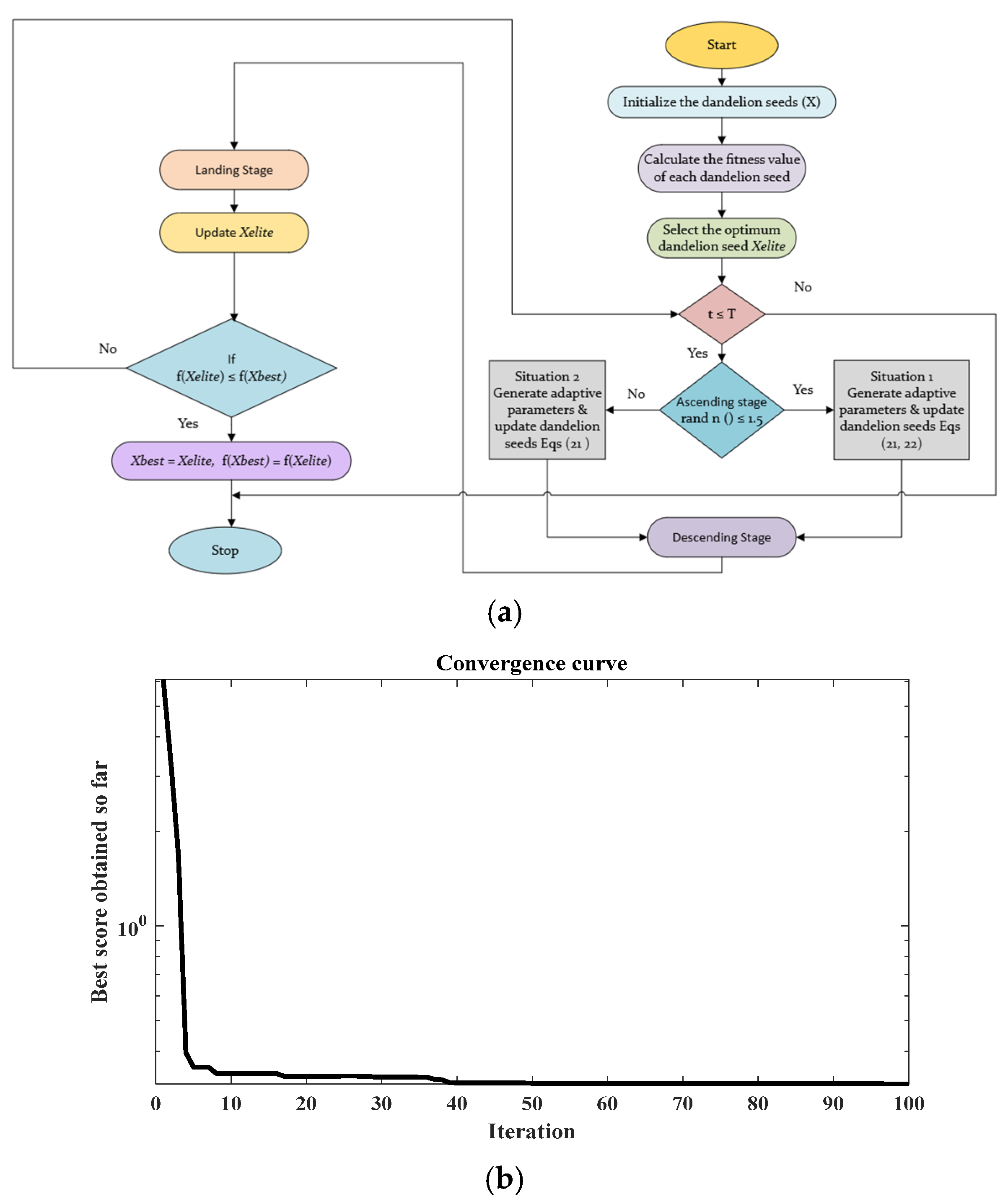
Section 3 provides a detailed description of the proposed VIDC integrated with the FO-VPSC. Also, the optimization algorithm based on the DO is covered in
Section 4. The simulation results and discussion are shown in
Section 5. Lastly,
Section 6 presents the research conclusions.
2. Description and Modeling of the System
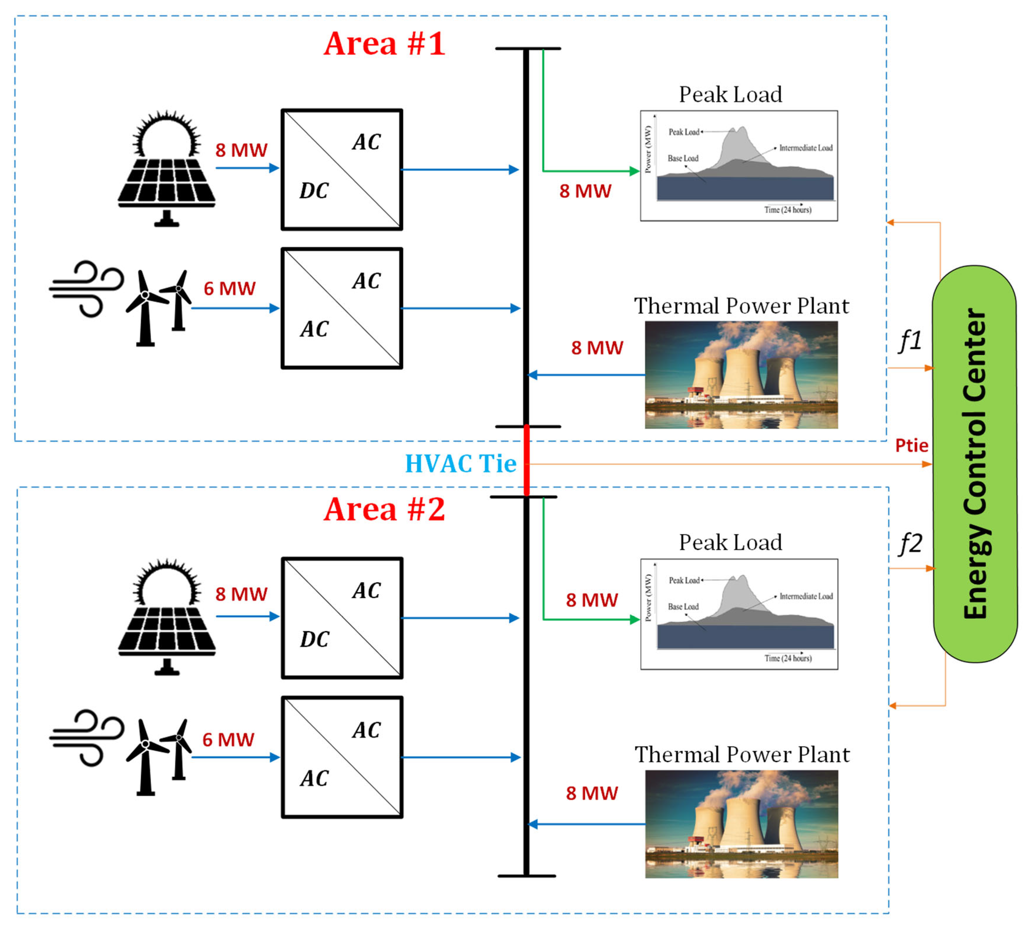
The structure of the two-area linked contemporary power system under investigation that incorporates the VIC method is shown in
Figure 1. An electricity transmission cable known as the tie-line has connected the two regions. A thermal power plant, load, and VIC based on ESS are present in every location. Additionally, areas 1 and 2 now feature wind farms and PV solar farms, respectively. There is an 8 MW solar PV farm in the first region and a 6 MW wind farm in the second. The frequency and tie-line power of the two regions are managed by the system controller. It then produces the area-specific control signals.
The converters shown in
Figure 1 are power electronic converters such that AC/AC converter is a voltage regulator, and that DC/AC converter is an inverter. To simulate the system being studied, linked power systems may be regulated using the low-order models of the individual generating units [
28,
29].
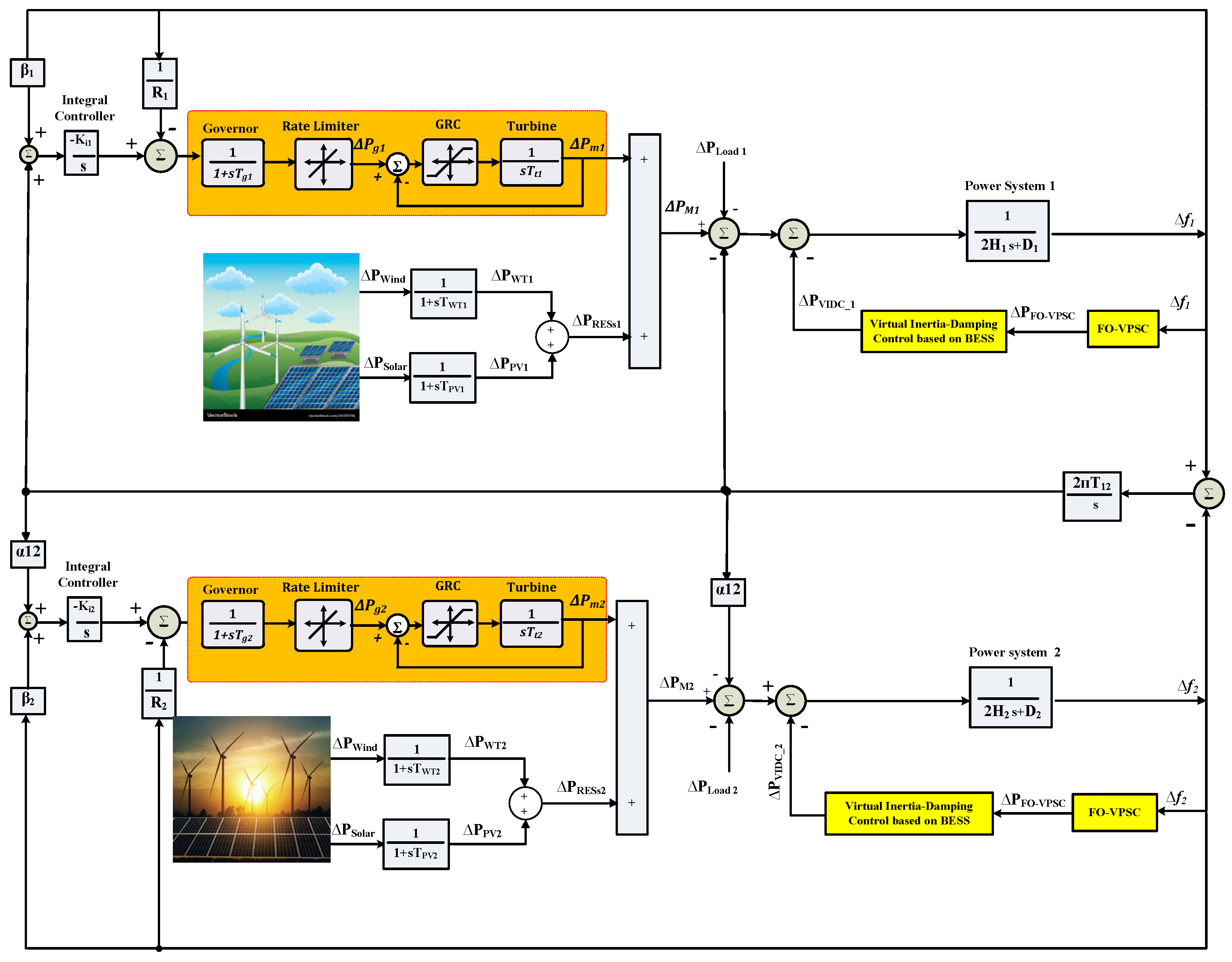
Figure 2 displays the linear model of the two-area linked power system under study using VIC technology. Furthermore,
Table 1 displays the model parameters. The model treats the domestic load in each area as a disturbance. Wind and solar farms are also considered disturbances. The following is a representation of the frequency deviation of the planned interconnected power system of the jth area, taking into consideration the effects of VIC, LFC, and droop control:
This equation describes how frequency deviation evolves based on the balance between mechanical input power and electrical output power, moderated by system inertia and damping:
where the power generated in area j by the appropriate turbine system and heat generation system is indicated by Δ
Pgj and Δ
Pmj, respectively. The lowercase symbol “s” denotes the Laplace transform variable, where
s =
σ +
jω. All subsequent frequency-domain expressions are formulated using this standard Laplace notation, clearly distinguishing them from system parameters defined in the time domain. According to [
15], the area control error (ACE) is calculated as the linear sum of the tie-line power flow and the weighted frequency variation.
The ACE represents the combined deviation in frequency and tie-line power flow and drives the secondary control action to restore system balance.
To establish the connections between m areas in an interconnected power system, the tie-line power deviation between the j-area and the other areas may be computed as:
where
jk represents the area-j and area-k tie-line power exchange, and
Tjk is the coefficient of synchronization between areas and Δ
Ptie. This expression shows that tie-line power exchange between areas depends on the rotor angle difference, which is influenced by frequency dynamics.
State variables of Equations (1) to (4) may be used to build the linearized state-space model of the suggested power system:
where
U is the ACE signal for the power system under discussion, X is the state vector of the system under examination (i.e., frequency deviation for each area), Y is the output, and W is the input perturbation vector (i.e., loads and RESs). C is the output of the system, E is the disturbance inputs, D is the zero vector of the same size as the controlled signal, F is the zero vector of the same size as the disturbance input vector, and B is the control output signal. Consequently, the complete matrix of the state space form of the suggested two-area linked power system with RESs may be obtained as follows:
3. Proposed Enhanced Virtual Inertia-Damping Control Strategy
In traditional power systems, SGs act as the main sources of inertia by storing kinetic energy in their rotating masses. They also offer natural damping through mechanical friction and electrical losses, both of which are essential for preserving system frequency stability [
15]. However, as RESs increasingly replace SGs, the system’s inherent inertia declines because inverter-based units lack rotating components [
30]. Consequently, modern low-inertia grids exhibit greater sensitivity to disturbances. To mitigate this issue, the VIDC concept has emerged, aiming to replicate the inertial and damping behavior of SGs through advanced control strategies applied to RES-interfaced inverters and supported by ESSs [
7]. The subsequent subsections discuss the development and evolution of the VIDC paradigm.
3.1. Conventional VIDC Strategy
In conventional VIC schemes, the dynamic behavior of an SG prime mover is emulated to improve the frequency stability of low-inertia power systems. This approach counteracts the loss of natural rotational inertia brought on by the high penetration of RESs by injecting synthetic active power into the system during frequency disturbances [
7]. A key element of VIC is the RoCoF, which serves as a critical indicator of system stability and is widely employed for rapid load shedding, frequency containment, and grid disconnection detection. The VIC mechanism leverages the RoCoF signal to monitor frequency deviations and generate appropriate active power compensation, thereby accelerating the system response during under- or over-frequency events [
15]. The RoCoF-based control action, which forms the core of conventional VIC, can be generally expressed as a derivative-based control law, in the time domain,
where
is the virtual inertia gain and
denotes the frequency derivative.
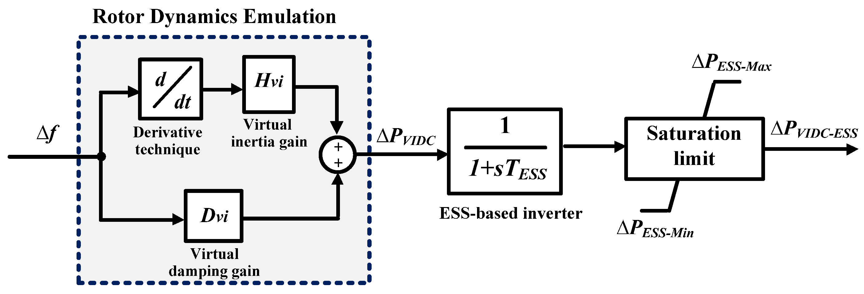
While VIC replicates the inertial response of conventional SGs, it neglects the damping characteristics, which are essential for suppressing oscillations and ensuring smooth frequency recovery. To address this limitation, the VIDC concept has been developed to emulate both the damping and inertia effects of SGs, thereby strengthening system stability under variable renewable conditions. The VIDC framework, illustrated in
Figure 3, emulates the rotor dynamics of an SG to provide a synthetic inertial and damping response. The dynamic power injected by the VIDC can be modeled, in the s-domain, as
where
is the virtual damping gain and
denotes the time constant of the inverter-based BESS. The VIDC generates additional active power support in response to frequency deviation and its rate of change, emulating physical inertia and damping.
Previous research has shown that incorporating both inertia and damping emulation significantly improves dynamic performance compared with conventional VIC systems that replicate only inertial behavior [
15]. Specifically, the addition of virtual damping enhances system response speed, reduces steady-state error, and improves oscillation suppression following disturbances. Building upon these principles, the next subsection presents the proposed VIDC strategy based on FO-VPSC, which extends the conventional approach by introducing fractional-order dynamics to achieve richer phase compensation and enhanced flexibility in frequency regulation.
3.2. Proposed VIDC Strategy Based on FO-VPSC
Although the conventional VIDC structure effectively emulates SG’s dynamics through inertia and damping replication, its performance is limited under nonlinear and uncertain conditions commonly associated with renewable-rich systems. In particular, the integer-order control framework provides restricted flexibility in shaping the dynamic frequency response, often resulting in inadequate phase and gain margins during high-rate disturbances. To overcome these limitations, this study introduces an enhanced VIDC scheme integrated with a FO-VPSC mechanism.
In traditional power systems, frequency regulation is achieved through hierarchical control loops: primary and secondary. The primary frequency control, implemented via the turbine governor of SGs, adjusts mechanical input power based on droop characteristics to maintain system frequency within permissible limits [
4]. The secondary frequency control, typically known as LFC, restores the nominal frequency and scheduled tie-line power after a disturbance within a time window of a few seconds to minutes [
4]. Inspired by this structure, analogous virtual primary and secondary control loops are constructed in converter-dominated systems using Virtual Synchronous Generators (VSGs). In this study, the virtual primary controller acts as a tilt controller that emulates droop behavior, while the virtual secondary controller functions as a fractional-order integral controller, responsible for long-term frequency restoration. The fractional-order formulation enables finer adjustment of the control dynamics compared with conventional integer-order designs, providing enhanced adaptability to grid uncertainties.
The proposed FO-VPSC framework extends the conventional VIDC model by embedding fractional-order lead–lag dynamics in both virtual primary and secondary control loops. This configuration allows richer phase compensation and smoother damping characteristics, thereby improving transient and steady-state performance. The active-power support injected by the proposed controller can be expressed as
where
and
denote the virtual primary control gain (i.e., tilt gain) and virtual secondary control gain (i.e., integral gain), respectively, while n and λ represent the fractional operator of tilt and integral controllers. This fractional-order control law adjusts the response by shaping both the dynamic (primary-like) and steady-state (secondary-like) components of frequency support.
The FO-VPSC parameters are optimally tuned using the Dandelion Optimizer (DO) to minimize the Integral of Time-Weighted Absolute Error (ITAE) of frequency deviation while satisfying stability constraints. The architecture of the proposed controller, shown in
Figure 4, provides several technical advantages over conventional VIDC approaches:
- I.
Enhanced dynamic shaping: Fractional-order elements enable smoother and more accurate phase adjustment, improving response under fast-changing conditions.
- II.
Improved frequency restoration: The fractional integral component in the virtual secondary loop ensures faster frequency recovery with reduced overshoot.
- III.
Robustness to parameter variations: The controller maintains stable operation under varying RES penetration and up to 50% reduction in system inertia and damping.
In summary, the proposed FO-VPSC-based VIDC offers a flexible, robust, and scalable solution for dynamic frequency regulation in low-inertia renewable-dominated power systems, bridging the classical hierarchical control philosophy of SGs with modern fractional-order control theory.
In this study, frequency stability refers to the ability of the power system to maintain its frequency within acceptable limits around the nominal value (50 Hz) under disturbances such as load variations and fluctuating renewable generation. Specifically, the system is considered frequency-stable if deviations remain within defined bounds, with controlled overshoot and settling time, ensuring reliable operation of the interconnected network. This definition is used as a basis for evaluating the performance of the proposed FO-VPSC–based VIDC strategy.
3.3. Fractional-Order Controller
Any real number may be symbolized as a generic differential or integral notation by using fractional operators in the controller [
31]. The FO differentiator’s fundamental mathematical relation may be written as follows: (It can be thought of as a common form of differential or integral operators.)
where
u and
l stand for the upper and lower bands, respectively, and
is the FO operator. The FO principle may be defined by two theories, one of which is Riemann–Liouville (RL), the first technique for figuring out the order derivative of a function f(t), as shown below [
32]:
where
n − 1
< < n.
The Laplace approach may be used to convert the fractional derivative of RL that has been determined in (11), as seen in (13) [
33]. A second definition related to the idea of FO is the Caputo definition, which allows us to describe the time-domain representation of the
nth order of the function f(t) as shown in (14).
Examining (15), a Laplace transformation of (14), provides a physical interpretation for the integral order. Consequently, the physical significance of the integral order is indicated by its beginning state.
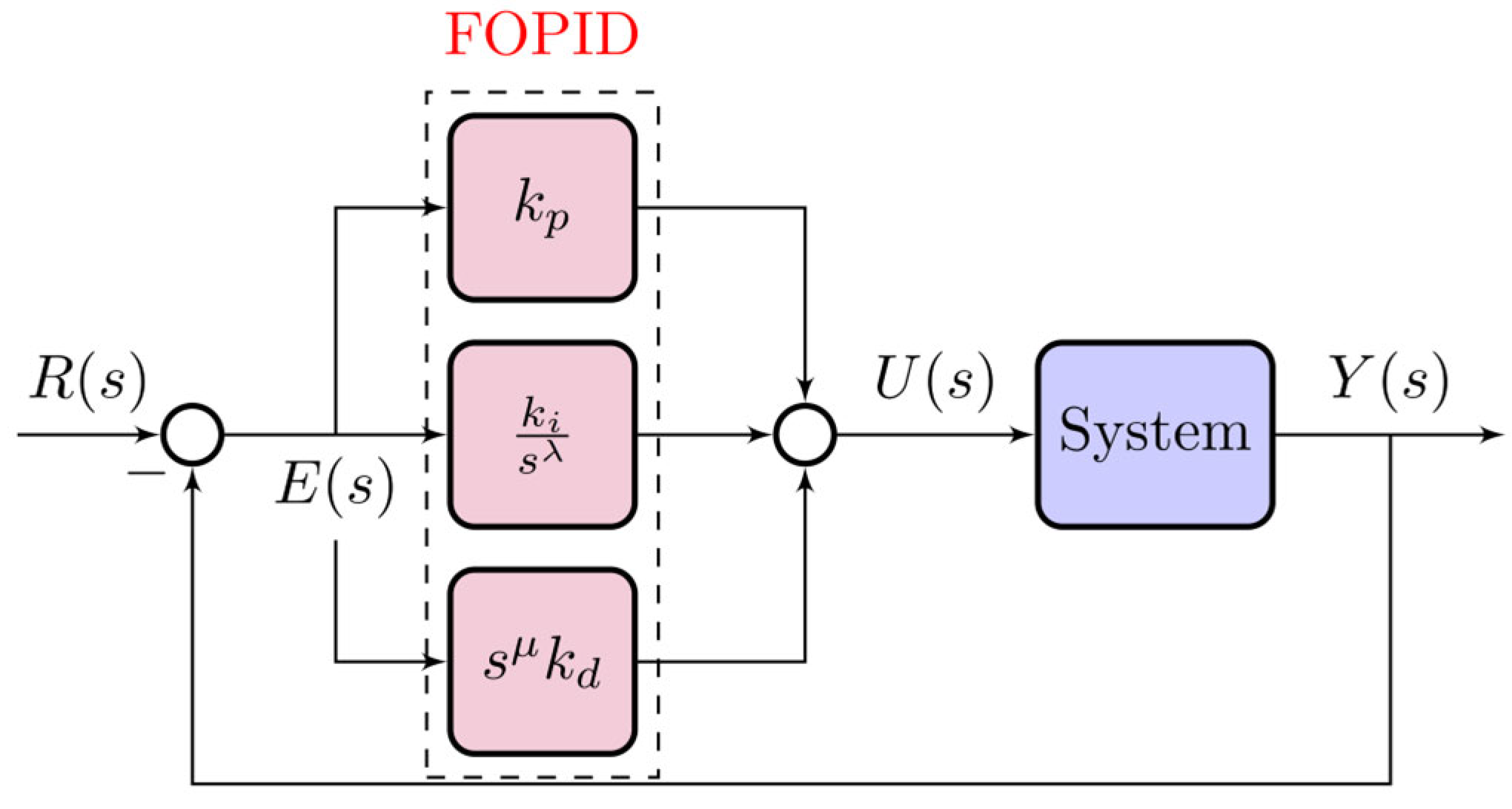
A FOPID controller includes five parameters plus two additional parameters of integral and fractional order, as shown in
Figure 5, which is given in terms of the integral and fractional order of the parameters. (16) gives the complete transfer function of the FOPID. When compared to a conventional PID, it has been demonstrated that these factors can boost the controller’s steady-state error, stability, and transition time. Furthermore, it gives the controller greater adaptability, enabling it to handle a variety of system disruptions:
where
and λ are normally positive fractions. The fractional-order parameters
and
are assumed to be positive (
) to preserve the intended derivative and integral effects. Non-positive values may lead to non-physical behavior or instability. The optimal values of these parameters are determined via the Dandelion Optimizer within these bounds.
3.4. Theoretical and Practical Validation
To ensure the theoretical soundness and practical feasibility of the proposed control scheme, a comprehensive analytical and validation framework is adopted. The mathematical formulation of the proposed FO-VPSC is systematically derived from the classical swing equation and the SG emulation principle. Fractional-order operators are employed to enhance dynamic flexibility and enable finer shaping of the phase and damping characteristics.
From a practical perspective, the FO-VPSC scheme is implemented and tested on a two-area interconnected renewable-dominated power system comprising heterogeneous sources, including thermal, solar, and wind units, as well as BESSs. This configuration reflects realistic operating conditions of modern low-inertia grids. To evaluate the robustness and adaptability of the control approach, several simulation scenarios are conducted under random renewable fluctuations and step-load perturbations. Moreover, a sensitivity analysis is performed to assess the controller’s performance under varying inertia and damping parameters. The obtained results demonstrate that the proposed FO-VPSC maintains stable operation and superior dynamic performance under all tested conditions, thereby confirming its practical viability for real-world power system applications.
5. Results and Discussion
This section provides a thorough assessment of the suggested VIDC with the FO-VPSC under various operating conditions and disturbance scenarios. To thoroughly assess its effectiveness, four distinct test scenarios are designed to reflect realistic operating challenges in low-inertia, renewable-dominated interconnected systems, as summarized below.
5.1. Scenario 1: Evaluation of System Performance Under Step Variations in Load and RES Generation
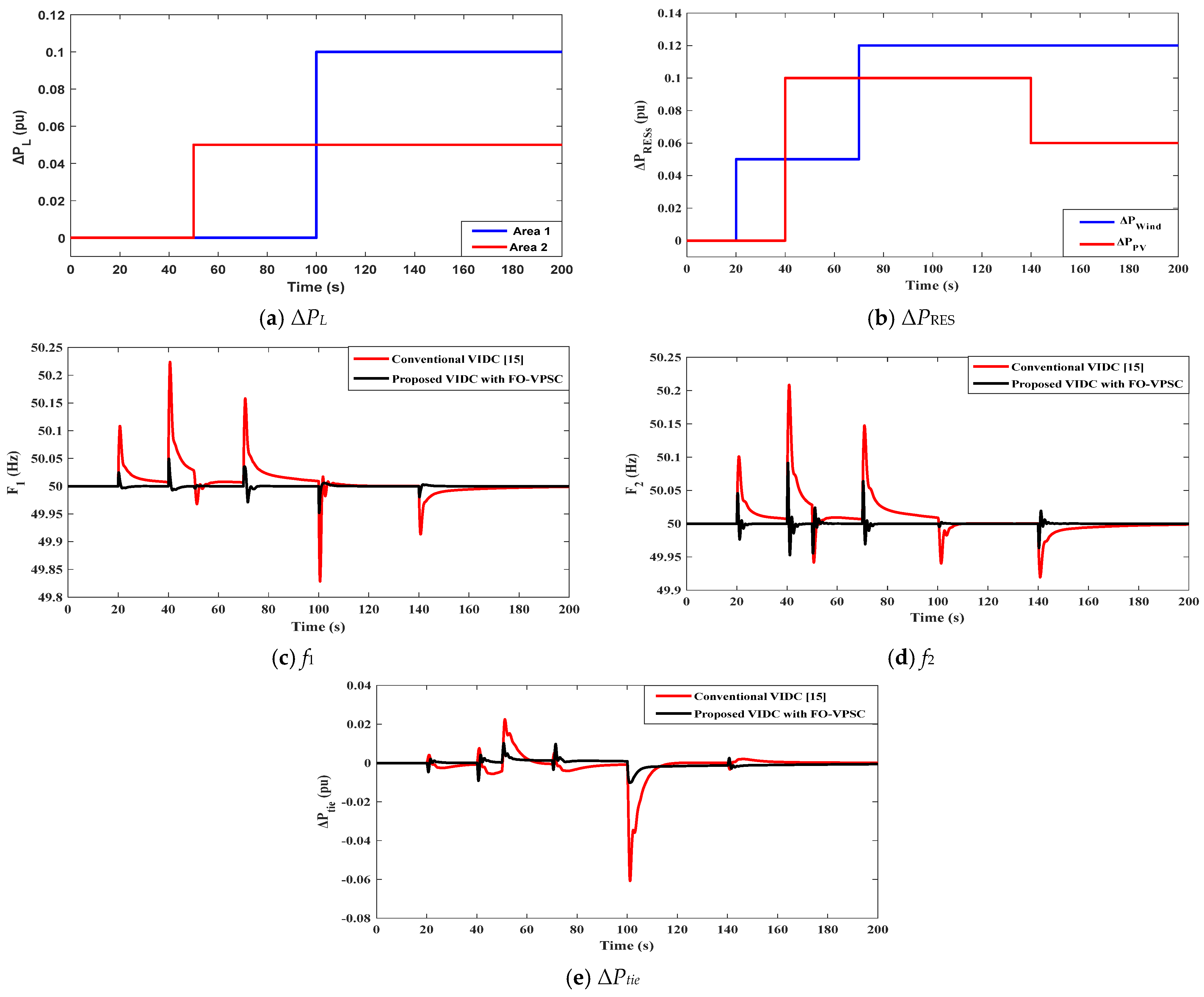
Figure 7 shows the composite disturbance scenario and the resulting dynamic behavior for scenario 1. In
Figure 7a, the step-load pattern applies two demand shocks: Area 2 receives approximately +0.05 pu at t ≈ 50 s, while Area 1 receives approximately +0.10 pu at t ≈ 100 s, i.e., the second step is about twice the first. In
Figure 7b, the RES injections change in overlapping steps: wind increases by ≈+0.05 pu at 20 s and reaches ≈+0.12 pu at 70 s; PV rises by ≈+0.10 pu at 40 s and later reduces to ≈+0.06 pu at 140 s. This timing produces sustained net-generation swings both before and after the 100 s load step, creating a demanding test for inertia and damping support.
Figure 7c,d show that the proposed VIDC with FO-VPSC markedly improves frequency quality in both areas compared with the conventional VIDC. In Area 1 (
Figure 7c), the conventional controller exhibits sizable excursions during the early RES steps, with overshoots of about +0.10–0.12 Hz around 20 s and about +0.25 Hz near 40 s, followed by an undershoot of roughly −0.06 to −0.08 Hz around 70–80 s. The +0.10 pu load at 100 s produces a deep nadir around 49.82 Hz. Under FO-VPSC, the same events are confined to ≈ ±0.05–0.08 Hz, and the 100 s nadir improves to ≈ 49.95 Hz, with settling to |Δf| < 0.02 Hz in ≈5–10 s. In Area 2 (
Figure 7d), the conventional VIDC reaches ≈+0.10 Hz at 20 s and ≈+0.2 Hz at 40 s; after 100 s, the frequency shows a slow tail and additional dips around the PV reduction at 140 s. The proposed FO-VPSC constrains Area-2 deviations to ≈±0.05–0.07 Hz during the RES steps and ≈−0.05 to −0.07 Hz following the 100 s event, with a visibly faster decay after each disturbance.
Figure 7e indicates how the tie-line power exchange reflects these improvements. With the conventional VIDC, sharp swings align with the RES steps and the 100 s load event, including a negative power deviation of roughly −0.05 pu at 100–110 s and multiple high-frequency ripples, signaling under-damped power sharing. With the proposed FO-VPSC, pulse magnitudes shrink to about −0.015 to −0.02 pu, and residual oscillations decay within ≈8–12 s (compared with ≈30–40 s), while the pre-100 s auxiliary actions are smoother and shorter-lived. This shows that the fractional-order loops supply the required virtual inertia and damping without over-injection, thereby reducing tie-line stress and BESS throughput while enabling the faster, well-damped frequency recovery observed in
Figure 7c,d.
5.2. Scenario 2: Evaluation of System Performance Under Integration of RESs with Random Load Disturbance in Area 1 and 5% Step Load Perturbation in Area 2 at t = 500 s
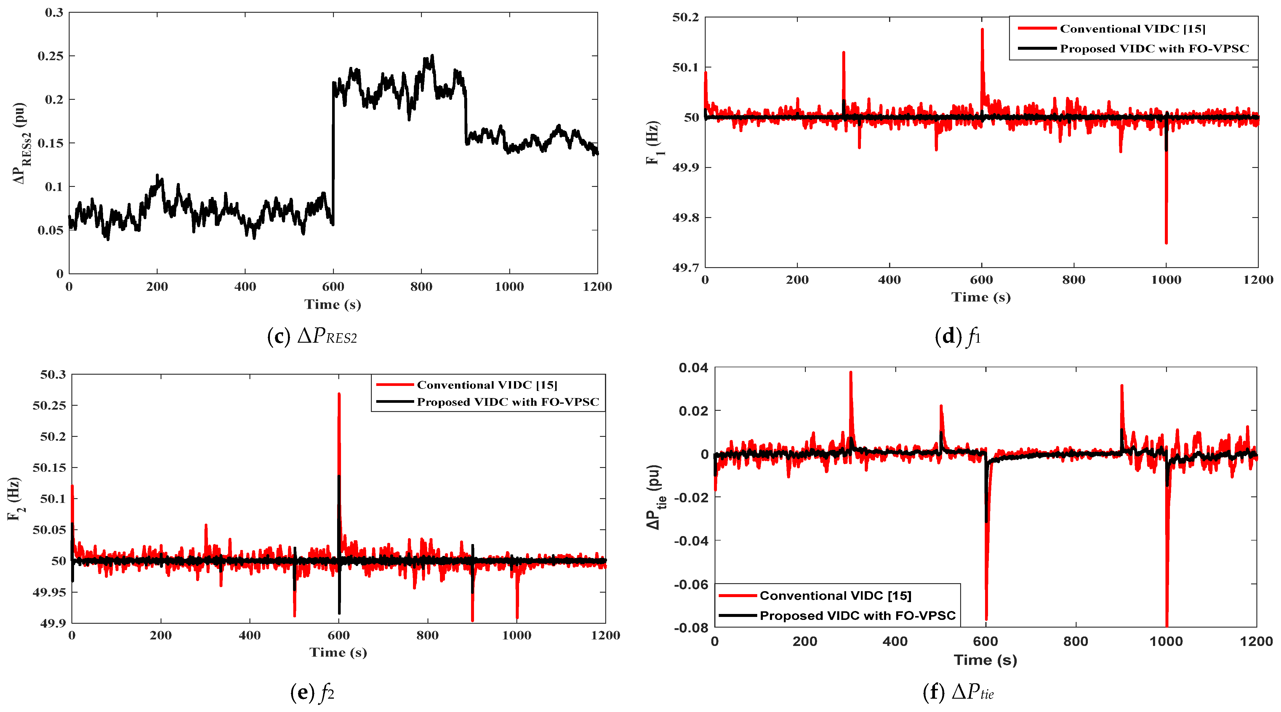
Figure 8 shows the performance of the studied system in the presence of the intended VIDC integrated with the FO-VPSC under the incorporation of RESs in each area when subjected to the load disturbance profiles defined in Scenario 2. The Area-1 demand is a bounded random process (
Figure 8a) that fluctuates around ≈0.112 pu with a peak-to-peak spread of ≈0.015 pu (≈0.105–0.120 pu). The short correlation time (tens of seconds) creates frequent small ramps that emulate realistic stochastic consumption. In parallel, the renewable injections follow asynchronous regimes:
Figure 8b (RESs-1) sits near 0.14–0.17 pu up to ≈300–320 s, steps up to ≈0.22–0.24 pu for most of the mid-horizon, then drops sharply to ≈0.05–0.07 pu at ≈1000 s;
Figure 8c (RESs-2) remains ≈0.06–0.10 pu up to ≈600 s, rises in a step to ≈0.20–0.24 pu, and later relaxes to ≈0.15–0.17 pu after ≈900 s.
Figure 8d (Area-1 frequency) and
Figure 8e (Area-2 frequency) show that the proposed VIDC with FO-VPSC keeps |
f| tightly bounded across the full 0–1200 s horizon, in contrast to the conventional VIDC. In Area 1, the conventional controller produces repeated spikes of about +0.10 Hz near 300 s and +0.20 Hz around 600 s, followed by a severe nadir at 1000 s reaching ≈49.72 Hz. With FO-VPSC, the same events are contained within roughly ±0.03–0.05 Hz, including the ≈1000 s renewable drop where the nadir remains near 49.94–49.95 Hz (Δf ≈ −0.05 to −0.06 Hz). In Area 2, the 5% SLP at 500 s is followed by the largest conventional excursion at 600 s, peaking around 50.25–50.28 Hz (Δf ≈ +0.25 to +0.28 Hz) and accompanied by undershoots down to ≈49.85–49.90 Hz (Δf ≈ −0.10 to −0.15 Hz) across the run; by contrast, FO-VPSC limits the 600 s event to ≈50.15–49.92 Hz and keeps the remainder of the trace within about ±0.04–0.05 Hz.
Figure 8f shows the power exchange of the tie-line, highlighting the contrast between the conventional VIDC and the proposed VIDC with FO-VPSC under Scenario 2 disturbances. The conventional controller (red) produces impulsive, underdamped actions: positive bursts of about +0.02–+0.03 pu around 300–350 s and near 900 s, a sharp negative pulse at 600 s reaching ≈−0.06 to −0.08 pu (following the 5% SLP at 500 s and the RESs-2 step up), and the largest deficit close to 1000 s with a plunge of ≈−0.08 pu associated with the RESs-1 drop. In contrast, the proposed FO-VPSC (black) confines these events to smaller, well-damped corrections: at
t = 600 s the undershoot is limited to ≈−0.012 to −0.015 pu and returns toward zero within roughly 10–12 s, while near 1000 s the undershoot remains capped around ≈−0.02 to −0.03 pu with similarly quick recovery. Across the 0–1200 s horizon, the FO-VPSC trace stays clustered within about ±0.01 pu during routine fluctuations, indicating reduced tie-line stress and more economical BESS throughput despite the stochastic Area-1 load and asynchronous RES ramps.
5.3. Scenario 3: Assessment of the System Performance Considering the Integration of RESs, Random Load Variations in Area 1 and Area 2, and a 50% Reduction in the System Inertia (H) and Damping (D) Parameters
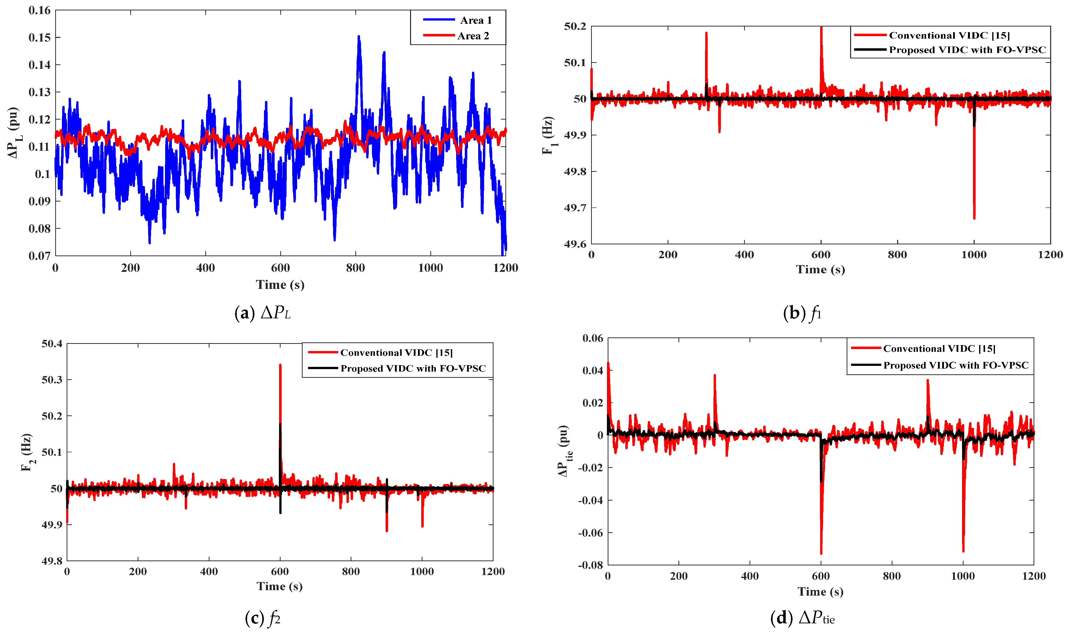
Figure 9 illustrates the system performance under Scenario 3, which involves the integration of RESs (
Figure 8b for area 1 and
Figure 8c for area 2), random load variations in both areas, and a 50% reduction in inertia (H) and damping (D) parameters. In
Figure 9a, the load demand in Area 1 (blue) fluctuates between approximately 0.10 pu and 0.12 pu, with intermittent peaks reaching around 0.15 pu near 820–930 s, while Area 2 (red) remains tightly clustered around 0.11 pu with deviations of about ±0.005 pu.
Figure 9b,c show that, with 50% reduced H and D, the proposed VIDC with FO-VPSC tightly bounds frequency excursions in both areas compared with the conventional VIDC. In Area 1 (
Figure 9b), the traditional controller produces visible spikes of about +0.18 to +0.20 Hz near 300 s and 600 s and a severe nadir at 1000 s, down to ≈49.68 Hz. The proposed FO-VPSC trace remains clustered within roughly ±0.04 to 0.06 Hz over the run, with the 1000 s nadir limited to 49.92 Hz. In Area 2 (
Figure 9c), the conventional VIDC shows the dominant event at 600 s, peaking around 50.35 Hz, alongside recurrent undershoots of ≈−0.10 to −0.15 Hz between 850 and 1050 s; by contrast, the proposed FO-VPSC caps the 600 s rise to 50.15 Hz and holds the remainder within ≈±0.05 Hz.
Figure 9d highlights the dominant exchange events: the conventional VIDC (red) produces repeated positive bursts of ≈+0.02 to +0.03 pu (≈300–350 s and ≈850–900 s) and two large undershoots, ≈−0.06 to −0.07 pu at ≈620 s and ≈−0.06 to −0.07 pu near
t = 1000 s, whereas the proposed FO-VPSC (black) limits the same events to ≈−0.012 to −0.015 pu around 620 s and ≈−0.02 to −0.03 pu near 1000 s, with routine fluctuations held within about ±0.01 pu despite the halved inertia and damping.
5.4. Scenario 4: Assessment of the System Performance Considering the Integration of RESs, High-Random Load Variations in Area 1 and Area 2, and an 80% Reduction in the System Inertia (H) and Damping (D) Parameters
Figure 10 illustrates the system performance under Scenario 4, which involves the integration of RESs (see
Figure 8b for Area 1 and
Figure 8c for Area 2), high-random load variations in both areas (see
Figure 8a), and an 80% reduction in the inertia (H) and damping (D) parameters. In
Figure 10a, Area 1 (blue) wanders around 0.19–0.22 pu with frequent surges up to 0.28–0.30 pu near 800–950 s, while Area 2 (red) clusters near 0.09–0.12 pu but exhibits deep dips to 0.03–0.05 pu and peaks at 0.14–0.15 pu.
Figure 8b and
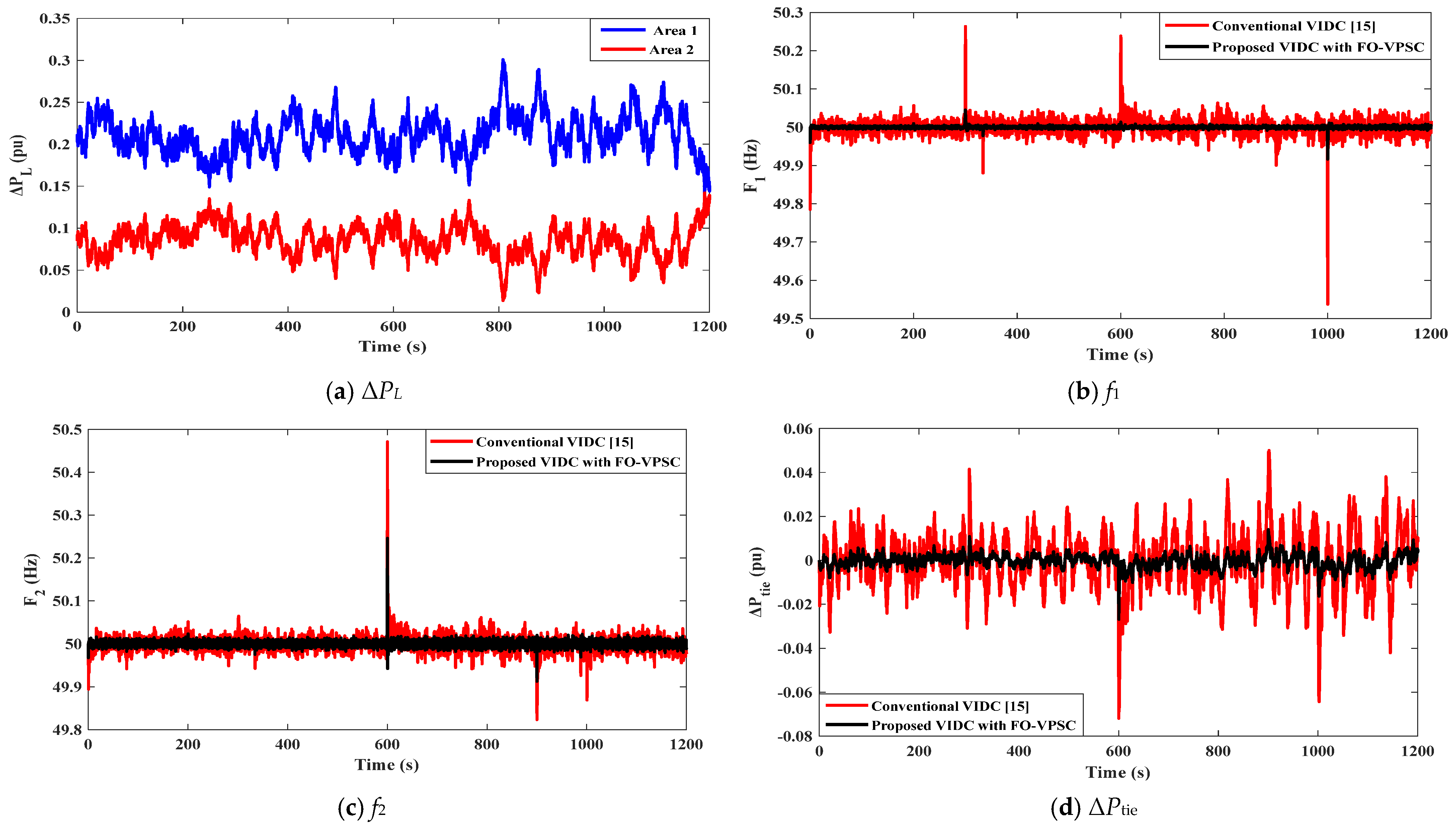
Figure 10c show that with 80% reduced H and D, the conventional VIDC (red) exhibits three dominant excursions, while the proposed VIDC with FO-VPSC (black) keeps |Δf| small. In Area 1 (
Figure 10b), spikes appear around t = 300 s and t = 600 s, reaching 50.25–50.30 Hz, followed by a deep nadir at t = 1000 s down to 49.55–49.60 Hz. In Area 2 (
Figure 10c), the largest event occurs near t = 600 s, where frequency peaks at 50.40–50.45 Hz, with recurring undershoots of ≈49.85–49.90 Hz later in the run. Across these events, the FO-VPSC trace remains clustered within roughly ±0.04–±0.06 Hz, notably curbing both peaks and dips at the same time instants. The corresponding exchange in
Figure 10d shows the conventional VIDC (red) generating dense spikes of ±0.02–0.04 pu and two dominant deficits: −0.06 to −0.07 pu at 600 s and −0.07 to −0.08 pu near 1000 s. The proposed VIDC with FO-VPSC (black) keeps routine fluctuations within about ±0.01 pu and limits those two events to −0.012 to −0.015 pu (600 s) and −0.02 to −0.03 pu (at 1000 s), evidencing much tighter power exchange despite the very low inertia/damping.
5.5. Scalability, Representativeness, and Practical Considerations of the Proposed Control
Although the proposed control strategy is tested on a two-area interconnected renewable-dominated power system, this configuration is a widely accepted benchmark for evaluating LFC and VIDC strategies. It effectively captures the dominant inter-area oscillation modes, tie-line power dynamics, and inertia interactions among heterogeneous energy sources. Moreover, the modular structure of the proposed FO-VPSC-based VIDC allows straightforward extension to larger multi-area networks by appropriately scaling the system matrices, controller gains, and communication paths according to the network topology and inertia constants. Therefore, the insights obtained from the two-area validation are representative and can be generalized to practical large-scale power systems. In addition, while communication delays and data transmission constraints are not explicitly modeled in this study, the fractional-order control structure inherently enhances phase flexibility and provides adaptive damping characteristics, improving robustness against moderate delays. Similarly, measurement noise, converter nonlinearities, and other cyber-physical uncertainties are not directly considered; however, the FO-VPSC design offers intrinsic robustness through enhanced phase shaping and adaptive damping, which can partially mitigate the effects of these factors.
Future work will extend the proposed framework to multi-area systems and incorporate communication delays, measurement noise, converter nonlinearities, and cyber-physical uncertainties into the modeling and validation. Additionally, Hardware-in-the-Loop (HIL) testing will be employed to assess the practical performance, scalability, and resilience of the proposed control strategy in realistic operational environments.
6. Conclusions
This paper presented a developed virtual inertia and damping control (VIDC) strategy that embeds fractional-order virtual primary and secondary controls (FO-VPSC) and coordinates them with BESS-based inertia emulation. The FO-VPSC parameters were tuned by the dandelion optimizer to shape the phase and damping over a wide frequency range. Validation on a two-area renewable-dominated system with thermal, wind, PV, and BESS units demonstrated consistent gains across stress cases that mix step loads, asynchronous RES ramps, random load fluctuations, and severe reductions in inertia and damping. Across all scenarios, the proposed controller delivered smaller frequency excursions, faster recovery, and smoother tie-line/auxiliary power. Typical improvements observed in the simulations include a reduction in peak over-/undershoots by about 60–85%, settling times shortened by a factor of roughly 3–4, and a cut of large tie-line power pulses by about 50–65% compared with a conventional VIDC. These gains persisted under harsher operating points, including low- and high-random loads in both areas and 50–80% reductions in H and D, indicating strong robustness to uncertainty and low-inertia conditions. The smoother actions also imply reduced BESS energy throughput and lower inter-area stress. Future work will focus on hardware-in-the-loop tests, aging-aware BESS constraints, and coordination with market-based redispatch. Extending the approach to meshed multi-area grids and co-designing FO-VPSC with grid-forming converters are also promising directions. Overall, the results confirm that fractional-order phase shaping, coupled with BESS-based virtual inertia, is an effective path to stabilize low-inertia, RES-rich power systems.
