Article

Fractional-Order Negative Position Feedback for Vibration Attenuation

by
Marcin B. Kaczmarek
* and
Hassan HosseinNia
Department of Precision and Microsystems Engineering, Delft University of Technology, Mekelweg 2, 2628 CD Delft, The Netherlands
*
Author to whom correspondence should be addressed.
Fractal Fract. 2023, 7(3), 222; https://doi.org/10.3390/fractalfract7030222
Submission received: 12 January 2023 / Revised: 8 February 2023 / Accepted: 21 February 2023 / Published: 1 March 2023
(This article belongs to the Section Engineering)

Abstract

:
In this paper, a fractional-order extension of a negative position feedback (NPF) controller for active damping is proposed. The design of the controller is motivated by the frequency-domain loop shaping analysis, and the controller dynamics are defined to maintain the high-pass characteristics of an integer-order NPF. The proposed controller provides greater attenuation of a resonance peak of a flexible plant than the integer order equivalent with the same high-frequency gain. The stability and influence of tuning parameters on the behaviour of the proposed controller are analysed. The efficiency and feasibility of the fractional-order controller are demonstrated by implementing it on an experimental setup.

1. Introduction

Vibration issues are becoming increasingly important when lightweight structures are used in machinery. The reduced mass of moving components reduces the power required to achieve high levels of acceleration, which benefits performance. Unfortunately, without reducing overall dimensions, this can only be accomplished by using thin structures and low-density materials. This may introduce lightly damped low-frequency resonances into the dynamics of a structure, making it more susceptible to disturbances and causing slowly decaying vibrations. The desire to solve this problem leads to increased interest in active vibration control techniques.
The fixed-structure controllers are important from the industry point of view since they are easier to implement than the optimisation-based alternatives. The control structures are designed to be inherently robust and easy to tune, using general knowledge of the dynamics of a plant. This approach is often used for collocated resonant mechanical systems, which have the interlacing pattern of poles and zeros along the frequency axis. As a result, in absence of time delays or parasitic dynamics, the phase of a frequency response of a system with generalised force as input and generalised displacement as output always remains between 0 and 180 [1].
Velocity feedback (VF) is a popular strategy to increase damping in structures [2], while the principle of VF is simple and intuitive, high gain of the controller at high frequencies may lead to the amplification of noise and the destabilisation of the system in the presence of time delays and parasitic dynamics. Moreover, due to sensor dynamics, low-frequency components of velocity signals measured with commonly used sensors such as accelerometers or geophones are unreliable. As a consequence, low- and high-pass filters are often incorporated into the controller. Their presence influences the performance of VF and has to be included in the design process.
The dynamics of VF combined with a second-order band-pass filter tuned for a single frequency are equivalent to passive vibration absorbers [3]. Similar dynamics are used in resonant controllers. In these methods, a controller is a second-order element with its resonance frequency tuned to the frequency of the mode to be damped [4,5,6]. The resonance peak of the controller is used to increase the gain in the vicinity of the target mode. An example is a negative position feedback (NPF) controller, which has high-pass characteristics. The same goal is obtained in negative derivative feedback (NDF) by using a velocity signal and a controller with band-pass characteristics [7,8]. For single-mode systems, this design will prevent any impact on both high- and low-frequency dynamics.
Another type of resonant controller is positive position feedback (PPF) [9], which takes a generalised displacement as an input and has low-pass characteristics. Consequently, the system is robustly stable, even in the presence of time delays, but at the cost of lowering the dynamical stiffness of the system at low frequencies [5].
For all resonant controllers, damping is an important tuning parameter. In the absence of damping, the use of resonant controllers leads to peak splitting, where the resonance peak of the mode is replaced by a zero accompanied by new resonance peaks at lower and higher frequencies. This phenomenon is typical for coupled resonators and has been described for tuned mass dampers already in [10]. In standard tuning procedures for resonant controllers, the peaks are removed by shifting the corner frequency of the controller with respect to the mode and increasing the damping of the controller.
In this paper, we study the behaviour of the resonant vibration control system using the frequency-domain loop shaping approach and show that the creation of new resonance peaks in the peak splitting may be prevented by using fractional-order filters. As the main contribution, we introduce a new fractional-order NPF controller. We analyse the dynamics of the control element in the active vibration control context and show that it provides stronger resonance peak attenuation than the integer-order counterparts with the same gain. The efficacy of the proposed attenuator is demonstrated experimentally.
The use of fractional-order (FO) calculus has proven to be beneficial in engineering applications. Besides being used for modelling various electrical, thermal and biomimetic systems, as well as chaos and fractals [11,12,13,14,15], they found application in modelling of viscoelastic materials [16,17]. FO calculus also has the potential to improve the performance of controllers [18,19]. In the majority of available literature on FO control, the focus is on high-authority control [1], with FO PID (proportional–integral–derivative controller) as an example [20,21].
Several examples of FO low-authority controllers can also be found in the literature. In [22], an FO Integral Resonant Controller (IRC) has been developed. A commensurate order FO PPF controller has been proposed in [23], where the additional degree of freedom has been used to increase the roll-off of the filter at high frequencies in order to reduce the spillover. In [24], an FO PPF with three additional tuning parameters has been proposed for vibration control of structures with parameter perturbations; however, depending on the parameters selected, the controller may lose the low-pass characteristics typical for PPF. A fractional-order integral controller for collocated smart structures was proposed in [25] to improve the robustness of the closed-loop system to changes in the plant. In [26], a concept of fractional-order difference feedback for active damping was introduced.
Most of the FO controllers mentioned above are FO generalisations of a second-order filter, previously studied in [27]. While the same applies to the control element proposed in this paper, the contribution lies in clearly motivating the use of FO elements in active vibration control. We focus on the filters with (pseudo)poles close to the stability margins and their use for active damping, as studied in [28,29] and extended to non-commensurate order systems in [30]. The topic is also related to the study of fractional-order mass-spring-damper systems [31,32,33] and electronic resonators [34,35]. The use of alternative fractional-order generalisations, such as power-law filters [36,37], can also be justified by the analysis conducted in this work and is an interesting direction for future research.
The design of the FO controller proposed in this paper is motivated by a frequency-domain analysis. The loop-shaping objective for active vibration control in collocated systems can be described as a reduction in the amplitude of the sensitivity function [5,38]. In [38,39], the relationship between the open-loop frequency response function and closed-loop sensitivity functions is represented using the Sensitivity charts, similar to the Nichols charts. In [40], manual loop shaping is used for tuning a vibration controller in an industrial setting.
The remainder of this paper is organised as follows. Background information is provided in Section 2. In Section 3, we introduce the FO NPF controller and consider the influence of tuning parameters. In Section 4, we demonstrate the performance of the proposed controller with experiments. The conclusion of the paper is given in Section 5.

2. Background

In this section, we present preliminary information for the paper. After introducing the type of plants considered in this work, we provide some basic information about fractional-order control systems. Finally, we present the objectives for active vibration control in the loop-shaping fashion.

2.1. System Description

Figure 1 presents the collocated vibration control system as a single-input single-output feedback loop. The plant G can be a lightly damped lumped mass system or a flexible structure with a collocated sensor–actuator pair. The plant dynamics can be represented as the sum of the contributions of N eigenmodes of the system
G ( s ) = i + 1 N ϕ k , i 2 s 2 / ω i 2 + 2 ζ i s / ω i + 1 ,
where ω i , ζ i and ϕ k , i are the eigenfrequency, damping ratio and the kth element of the eigenvector of the ith mode. In the case of flexible continuous systems, a quasi-static correction for the influence of high-frequency modes can be added to the model [1].
The controller is implemented in a negative feedback configuration and is represented by a transfer function H ( s ) , as Figure 1 shows. The objective of the control system is to reduce the height of a resonance peak corresponding to a single target mode at frequency ω n without influencing other modes of the system.
The control system should also be robustly stable in the presence of uncertainty of modal parameters. An important property of the collocated system is that the poles and zeros of G ( s ) have an interlacing pattern [1]. As a consequence, the phase of G ( s ) is always between 0 and 180 . This property may be used to guarantee the robust stability of active control systems [1,5]. Unfortunately, it does not hold for systems with time delays, which may lead to instability if neither the controller nor the plant have high-frequency roll-off characteristics or if the plant is not sufficiently damped.

2.2. Fractional-Order Control

Fractional-order calculus has been developed to generalise conventional differentiation and integration to non-integer orders [41]. While there exists a vast number of definitions of FO operators, we use the Caputo derivative defined as
C D α f ( t ) 1 Γ ( m α ) 0 t f ( m ) ( τ ) ( t τ ) α m + 1 d τ ,
where α R + is the order of differentiation, and m is a positive integer such that m 1 < α < m .
The Laplace transform of Equation (2) is given by
L C D α f ( t ) = s α F ( s ) k = 0 m 1 s α k 1 f ( k ) ( 0 ) .
Note that for zero initial condition the Laplace transform of many FO operators is s α , which greatly simplifies the design of FO controllers in the frequency domain.
A continuous-time FO system is given by a transfer function of the form
H ( s ) = b m s β m + b m 1 s β m 1 + + b 0 s β 0 a n s α n + b n 1 s α n 1 + + a 0 s α 0 ,
with a , b R . In a commensurate-order system, all the orders of derivation are integer multiples of the base order α , i.e., β k = k α with k Z + , so the transfer function (Equation (4)) is given by
H ( s ) = k = 0 m b k ( s α ) k k = 0 n a k ( s α ) k ,
and can be presented as a pseudo-rational function H ( λ ) of the variable λ = s α
H ( λ ) = k = 0 m b k λ k k = 0 n a k λ k .
The shape of a transfer function can be described by defining its slope in certain frequency regions. A transfer function has a slope of q in a certain frequency range if its magnitude in this range is proportional to the q-th power of frequency ω q . For example, a high-pass filter F ( s ) = s s + ω f has a slope of + 1 at low frequencies ω < < ω f and slope 0 at high-frequency region ω > > ω f .
The stability of a fractional-order system can be assessed by studying its transfer function [41]. In general, the denominator of Equation (4) is not a polynomial and has an infinite number of roots. Among them, a finite number of roots belonging to the principle sheet of the Riemann surface will determine the system’s stability. The fractional-order system is bounded-input bounded-output (BIBO) stable if all of the roots of the denominator, which are in the principle Reimann sheet and are not the roots of the numerator, have negative real parts [42].
For a commensurate-order system represented by Equation (6), the stability condition is
| arg ( λ i ) | > α π 2 ,
where λ i are the roots of the characteristic polynomial in λ [41].
The stability of a closed-loop system containing a linear FO controller and a linear plant can be concluded using the frequency-domain Nyquist criteria [43].
A common way to implement an FO controller is to approximate it in an appropriate range of frequencies using finite-dimensional integer-order transfer functions. An overview of approximation techniques can be found in [44]. In continuous time, expansion-based and frequency-domain identification methods can be used to find the approximation. In the later category, the approximation can be found analytically, like in the method of Oustaloup [45], or identified directly from the desired frequency response using commercial software. While direct discrete-time approximation of FO systems exist, it is also possible to discretise a continuous-time approximation, which yields satisfactory results if the sampling ratio is sufficiently high.

2.3. Loop-Shaping for Active Vibration Control

The objectives of the control system can be formulated in the frequency domain by defining desired shapes of closed-loop and open-loop transfer functions. For the system presented in Figure 1, the closed-loop dynamics from the disturbance d and noise n inputs to the performance output x and measurement y are given by  
S = y n = 1 1 + G H ,
T n = x n = G H 1 + G H = S 1 ,
T = x d = G 1 + G H = G S .
In this case, the sensitivity function S acts as the vibration reduction ratio. It can also be related to the degree of robustness of the system [5]. In order to minimise excitation of the system dynamics by the measurement noise n, the transfer function T n should be as small as possible at all frequencies. This means that S 1 is required. The objective of attenuating a single vibration mode without influencing other dynamics of the system can be expressed by comparing the desired closed-loop and open-loop behaviour. At the frequency of the target mode, | T | < < | G | is required, while | T | | G | should be maintained at all other frequencies. This leads to | S | < < 1 and | S | 1 , respectively. To satisfy the conflicting requirements, the sensitivity function S should have a shape of a notch filter. In the vicinity of the resonance peak, the magnitude of S should be small to attenuate the resonance peak, and at the other frequencies, | S | should be equal to 1. The idea of loop-shaping is illustrated in Figure 2.
The loop shaping for active damping can be presented as follows:
  • Gain requirement: The ideal loop shape of the open-loop gain G H is triangular, which can be deduced from Equation (8). This means that G H should have a positive slope for ω < ω n and a negative slope for ω > ω n .
  • Phase requirement: The ideal triangular loop gain results in a region where the gain is above 1. This is required to provide high gain and reduce sensitivity at ω n . However, it results in two crossover frequencies that can be defined as
    ω c i = : { ω | ω R and G ( ω ) H ( ω ) = 1 } , i = 1 , 2 .
    To follow the ideal closed-loop gain, the sensitivity at the crossover frequency should be | S | 1 . Moreover, the open-loop phase at crossover frequency should satisfy
    ϕ ( ω c i ) = G ( ω c i ) H ( ω c i ) 120 .
With such a loop shape, the control system will have a strong influence on the frequency regions where the magnitude of G H is high and will not change the dynamics of the system elsewhere. It should be noted that PPF cannot satisfy the above requirements. PPF was created with a focus on assuring stability for flexible systems with uncertain dynamics. As a consequence, the use of PPF leads to the undesired amplification of the plant’s response at low frequencies. NPF controllers presented in the last plot of Figure 2 can only satisfy the gain requirement, while VF control can satisfy both requirements. However, VF decreases the slope of the triangular open loop from ± 2 to ± 1 compared to NPF. To solve this problem, this next section proposes a new element using fractional-order calculus.

3. Fractional-Order Negative Position Feedback Control

In this section, we present the main contribution of the paper and introduce the FO-NPF controller. First, the definition of the dynamics of the element is motivated with the frequency-domain analysis. Subsequently, we consider the stability and tuning of control systems containing the proposed controller.

3.1. Main Concept

To motivate the use of fractional-order resonant control, we will first more closely study the frequency-domain properties of the integer-order negative position feedback (NPF) controller [5]
H 2 = k f ( s / ω f ) 2 ( s / ω f ) 2 + 2 ζ f ( s / ω f ) + 1 ,
where ω f and ζ f denote the corner frequency and damping ratio of the filter, with a single degree of freedom plant
G T = 1 / k ( s / ω n ) 2 + 2 ζ s / ω n + 1 .
The integer controller satisfies the first requirement with a triangular loop gain G T H 2 of ± 2 slopes, which is beneficial since it limits both the low- and high-frequency spillover. The shape of the controller can be seen in Figure 2. Unfortunately, the steep slopes also have an adverse effect on the vibration attenuation performance of the system. Since the considered systems are linear, Bode’s magnitude–phase relationship holds [43], and the phase of the system with ± 2 slopes is equal to ± 180 , which is a violation of the second requirement. At regions where the loop gain G T H 2 has the phase of ± 180 , the response of the system is amplified, which can be seen from the sensitivity transfer S in Equation (8b). This limits the vibration attenuation performance of the system and leads to the creation of new peaks in the frequency response if the magnitude of the loop gain at these frequencies is close to 1. This behaviour can also be seen in other resonant controllers or tuned mass dampers [10].
The phase of the loop gain in the vicinity of the resonance peak is influenced by the damping ratio ζ f of the controller. Increasing ζ f increases the phase margin of the system, which leads to smaller secondary resonance peaks in a closed loop. It also leads to a lower gain of the open loop G T H 2 at the frequency of the target mode and its smaller attenuation. With an integer-order controller (Equation (11)), the secondary resonance peaks are always attenuated by the cost of reducing the attenuation of the target mode.
In order to relax this trade-off, we propose a fractional-order resonant controller
H α = k f ( s / ω f ) 2 α ( s / ω f ) 2 α + 2 ζ f ( s / ω f ) α + 1 ,
where k f denotes gain, ω f the corner frequency and ζ f the damping ratio. Equation (13) is a fractional-order generalisation of a second-order high-pass filter [27]. The slope of G T H α at lower frequencies is determined by the fractional-order α ( 0 , 1 ) of the controller and is equal to + 2 α . Decreasing the steepness of the magnitude response at low frequencies prevents the phase in this region from approaching + 180 . At the same time, the high resonance peak of the controller can be maintained to increase the magnitude at the target frequency. At high frequencies, the slope is determined by the plant dynamics and in the considered case is equal to 2 . While the second requirement for loop shaping is satisfied only for the lower zero-crossing frequency, it is sufficient to obtain a more desirable sensitivity S than in the integer-order case.
Tuning of the fractional-order attenuator in Equation (13) requires finding four parameters: the fractional-order α , the gain of the controller k f , the corner frequency of the controller ω f and its damping ratio ζ f . Below, we present the stability conditions for the fractional-order attenuator and analyse the influence of the tuning parameters on the shape of open- and closed-loop transfer functions.

3.2. Stability of the Fractional-Order Attenuator

The stability of second-order fractional systems has been studied in [28,29]. Here, we present only the specific results relevant to this paper. The fractional-order attenuator in Equation (13) is a commensurate-order system, so it can be represented by a pseudo-rational function H α ( λ ) , with λ = s α ,
H α ( λ ) = k f / ω f 2 α λ 2 1 / ω f 2 α λ 2 + 2 ζ f / ω f α λ + 1 .
The roots of Equation (14) are given by
λ 1 , 2 = ζ f ω f α ± j ω f α 1 ζ f 2 .
The stability condition (Equation (7)) states that the roots of a stable fractional-order transfer function must lie outside of a closed angular sector. For α = 1 , this condition is equivalent to the roots remaining in the left-half complex planeand can only be satisfied with positive damping coefficients. For α ( 0 , 1 ) , the stability region is larger, and the condition can also be satisfied by a fractional-order attenuator with ζ f < 0 . This leads to greater design freedom and allows for maintaining a high resonance peak for transfer functions with orders smaller than 2. As a consequence, stronger attenuation of the resonance in the plant can be achieved with an FO controller, which will be further elaborated on in the following sections.

3.3. Influence of the Tuning Parameters on the Attenuator

The definition of the FO attenuator in Equation (13) has been chosen such that the influence of the tuning parameters is similar to the integer-order case. This is contrary to the example presented in [24], where the conversion of a filter to an FO version significantly alters its character.
The influence of the gain of the attenuator k f and its corner frequency ω f are the same as in the integer-order case. Their change leads to the modification of the magnitude and shift of the controller along the frequency axis, respectively. The fractional-order α defines the slope of the controller in the low-frequency region. Additionally, it also influences the behaviour of the damping parameter ζ f .
The response of the attenuator (Equation (13)) at frequencies close to ω f is characterised by a resonance peak, similar to the integer-order case. The resonance peak can be measured by a quality factor Q, determined by the maximum value of the peak, relative to the crossing point of the low- and high-frequency asymptotes in the frequency response plot [46]. By evaluating Equation (13) with the assumption that the fractional-order attenuator has the peak of response at ω = ω f , we obtain
Q = ( 2 ζ f sin ( π 2 α ) + sin ( π α ) ) 2 + ( 2 ζ f cos ( π 2 α ) + cos ( π α ) + 1 ) 2 1 2 ,
which reduces to Q = 1 2 ζ f for α = 1 .
The equivalent damping for an attenuator with fractional-order α , which leads to the same Q-factor as for the integer-order attenuator with ζ f , α = 1 , is given by
ζ f , α = ζ f , α = 1 cos π 2 α ,
which is obtained by comparing the quality factor in Equation (16) with its integer-order equivalent and finding ζ f such that both are equal.
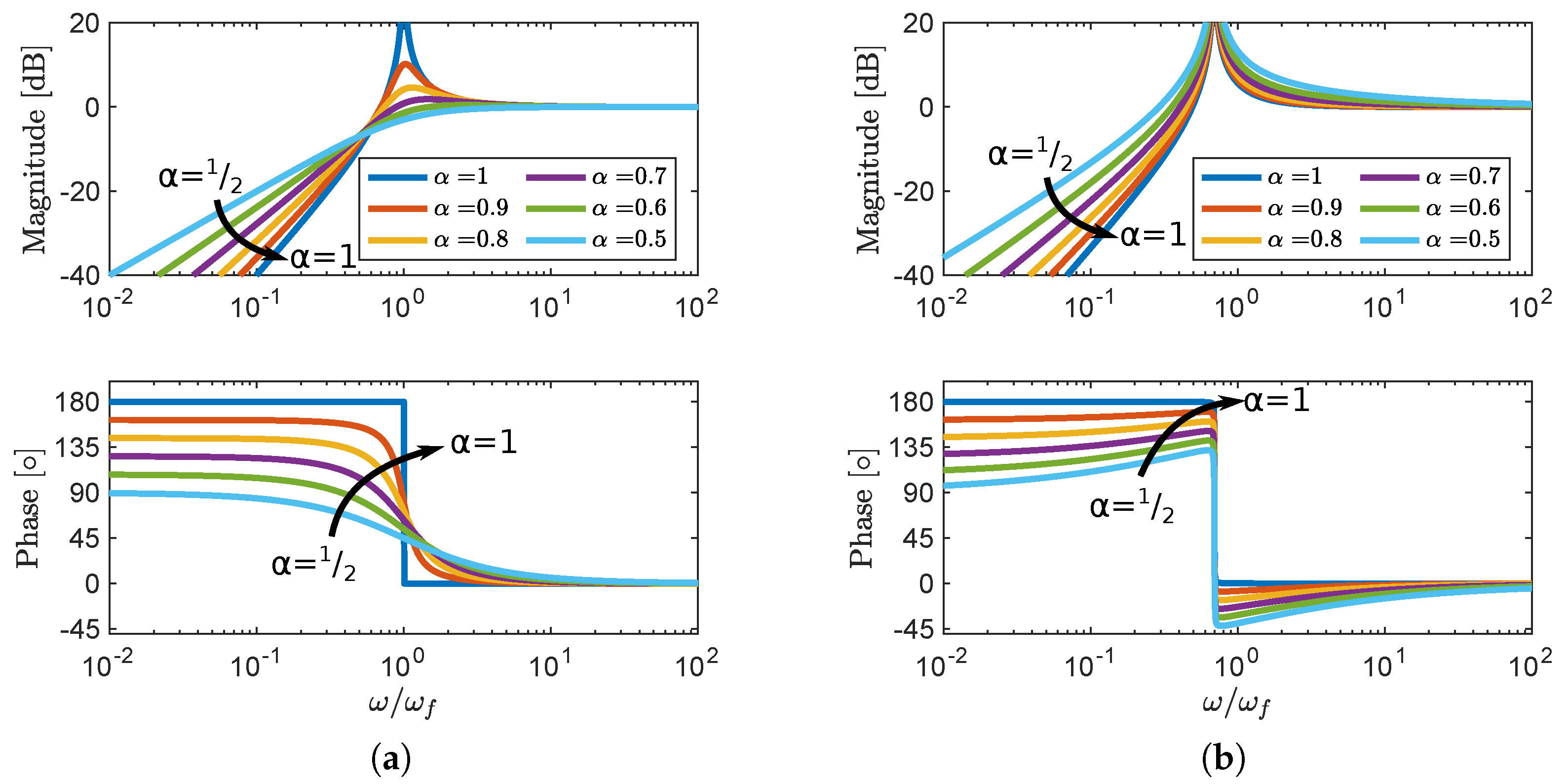
Figure 3 illustrates the influence of changing the fractional order of the attenuator. In Figure 3a, ζ f is kept constant. As a consequence, the height of the resonance peak decreases with decreasing order α . In Figure 3b, the values of ζ f are selected according to Equation (17) such that the oots of Equation (14) lie on the border of the stability region, i.e., satisfy | arg ( λ i ) | = α π 2 . Similar to a marginally stable integer-order mass-spring system without damping, the marginally stable FO resonator has an infinite resonance peak. When ζ f is adjusted such that a high resonance peak is maintained for all α , the phase in the vicinity of ω f may exceed the low- and high-frequency asymptotes. This may destabilise a closed-loop system, so the stability should be checked in the design process.
Note that all the above considerations, even in the integer case, are valid only for lightly damped systems. For attenuators with significant damping, the point with the maximal magnitude of the frequency response is shifted from the corner frequency ω f .

3.4. Influence of α on Open- and Closed-Loop Response

Following the convention used for the integer-order attenuators [10], we consider first the behaviour of marginally stable systems. The influence of increasing damping in the system is presented in the second step.
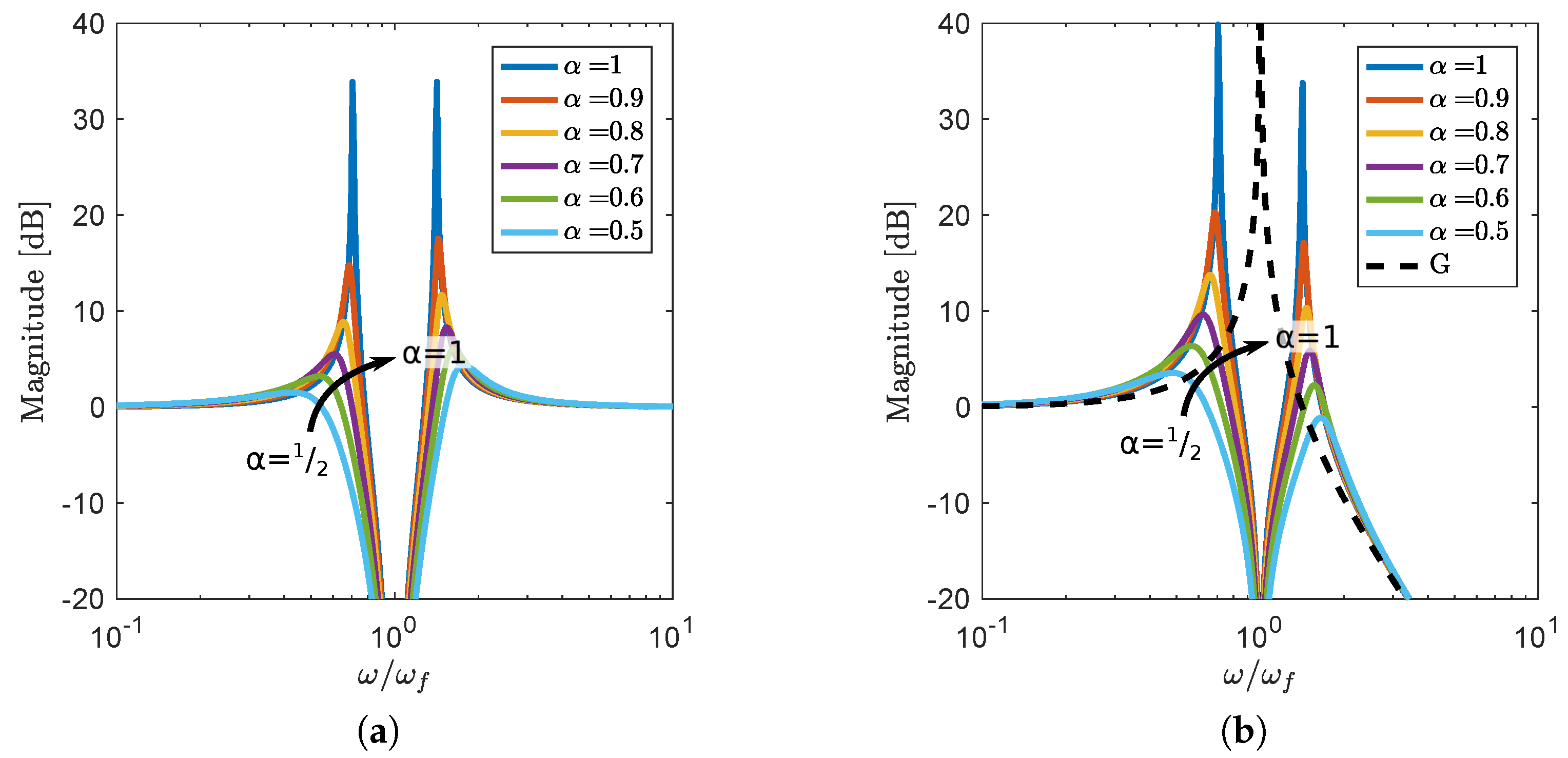
The phase of the loop gain G T H α with the fractional-order controllers does not approach ± 180 , and as a consequence, smaller new peaks are created, which was already highlighted as a motivation to use FO controllers. This is especially visible in Figure 4a, where the sensitivity function S is presented. When the resonance frequencies of the attenuator and the mode to be dampened are the same ω f = ω n , two uneven peaks are created in the closed-loop system (see Figure 4b). Similar behaviour can be seen in the tuned mass damper [10], and equal peaks can be obtained by adjusting the ω f .
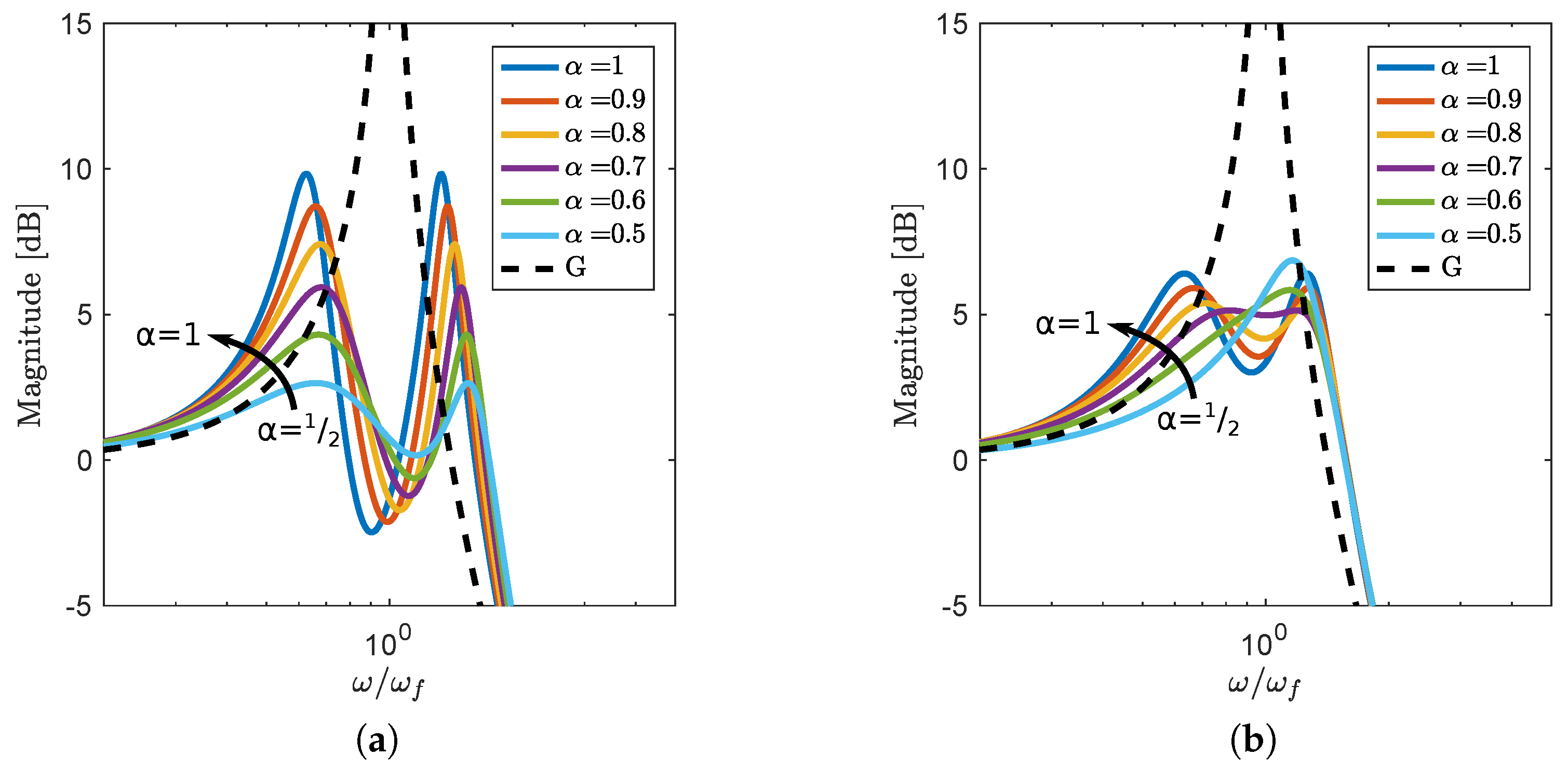
For low values of attenuator damping, the decrease in the factional-order α leads to improved resonance peak attenuation, similar to the marginally stable case presented in Figure 4. This is demonstrated in Figure 5, where the closed-loop dynamics of the system with the fractional-order attenuators with different damping are compared. For all values of α , equivalent damping has been calculated using Equation (17), so the responses can be compared. The gain of all controllers is kept constant, and the values of ω f are selected such that the value of the closed-loop H norm is minimised.
When damping is increased, the effectiveness of the attenuator no longer increases monotonically with the decrease in α , but an optimal value for which a nearly flat response in the vicinity of the resonance frequency of the plant is obtained can be found. In this case, the best attenuation of a resonance peak is obtained for certain values of k f , ω f and ζ f , α = 1 , which is illustrated in Figure 5b for ζ f , α = 1 = 0.4 .
In general, the optimal attenuation is achieved when ω f ω n . The shift in the corner frequencies depends on α and damping parameters ζ n , ζ f . If all other parameters are kept constant, the optimal ω f increases as α decreases, which is illustrated in Figure 6.

3.5. Heuristic Tuning Guidelines

To summarise the considerations on the FO NPF controller introduced in this paper, we provide heuristic tuning guidelines that may be helpful in obtaining an initial design of the controller. A common method of determining tuning parameters for resonant controllers is the fixed-point theory [10]. In this method, the gain of the controller (or the mass ratio in the case of a tuned-mass damper) is fixed as the main design parameter. In the integer-order case with an undamped single-mode plant, the presence of fixed points in the frequency response independent of the damping of the controller can be used to determine the remaining tuning parameters. However, even in the integer case, the parameters have to be adjusted to account for the presence of damping and other flexible modes in the system.
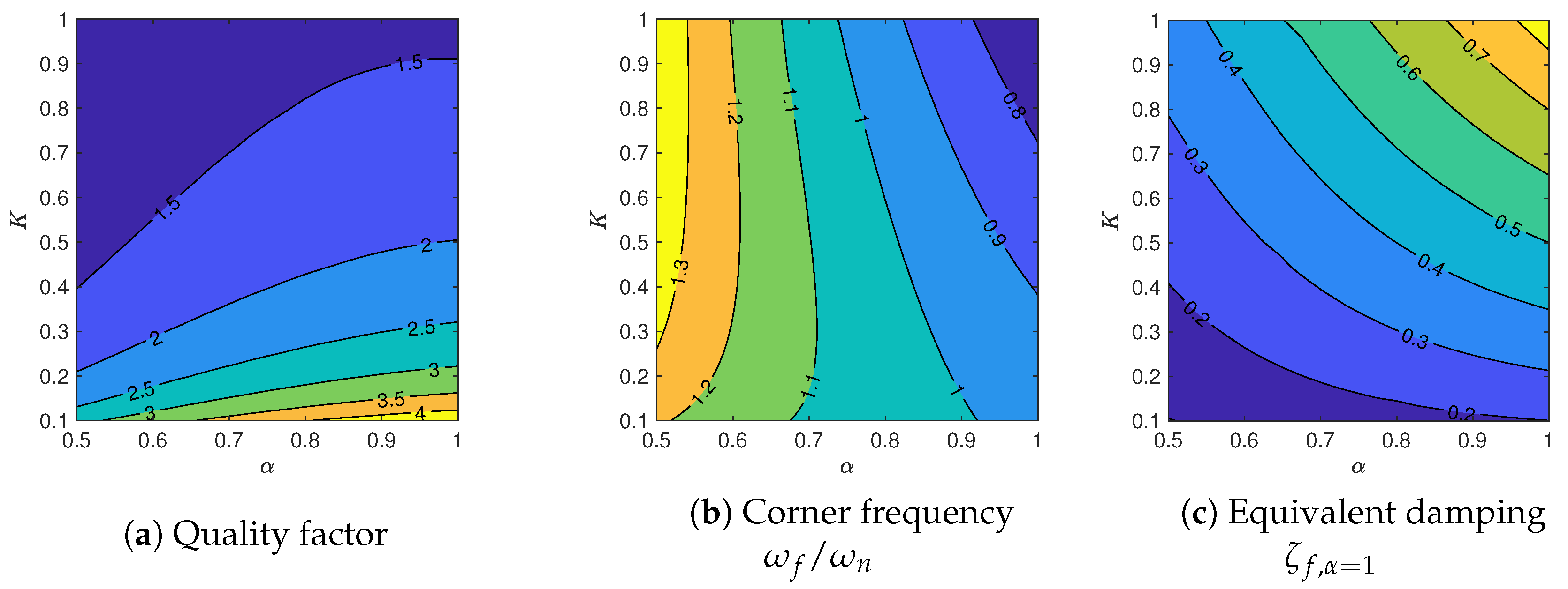
For systems with non-integer-order controllers, such fixed-points cannot be found. Moreover, the presence of FO derivatives significantly complicates analytical derivations. The tuning guidelines presented here are based on an optimisation study, in which the H norm of a closed-loop response of a plant (Equation (12)) with FO NPF (Equation (13)) with different gains k f and orders α was minimised, while the closed-loop stability was used as a constraint. The results of the study are presented in Figure 7. For fixed k f , the height of the resonance peak is decreasing monotonically as the α is lowered. The changes in optimal values of the corner frequency and damping ratio are also monotonic, which greatly simplifies the tuning procedure.
In a design process, integer-order NPF with parameters selected as described in Appendix A can be used as an initial design. The maximal gain of the controller k f that satisfies the requirements in terms of high-frequency spillover should be selected. Subsequently, the order α can be lowered as long as the requirements in terms of low-frequency spillover are met, which leads to a stronger attenuation of the resonance peak. The corner frequency and damping ratio should be adjusted to obtain a flat magnitude of the frequency response in the vicinity of the targeted resonance frequency of the plant.

4. Experimental Validation

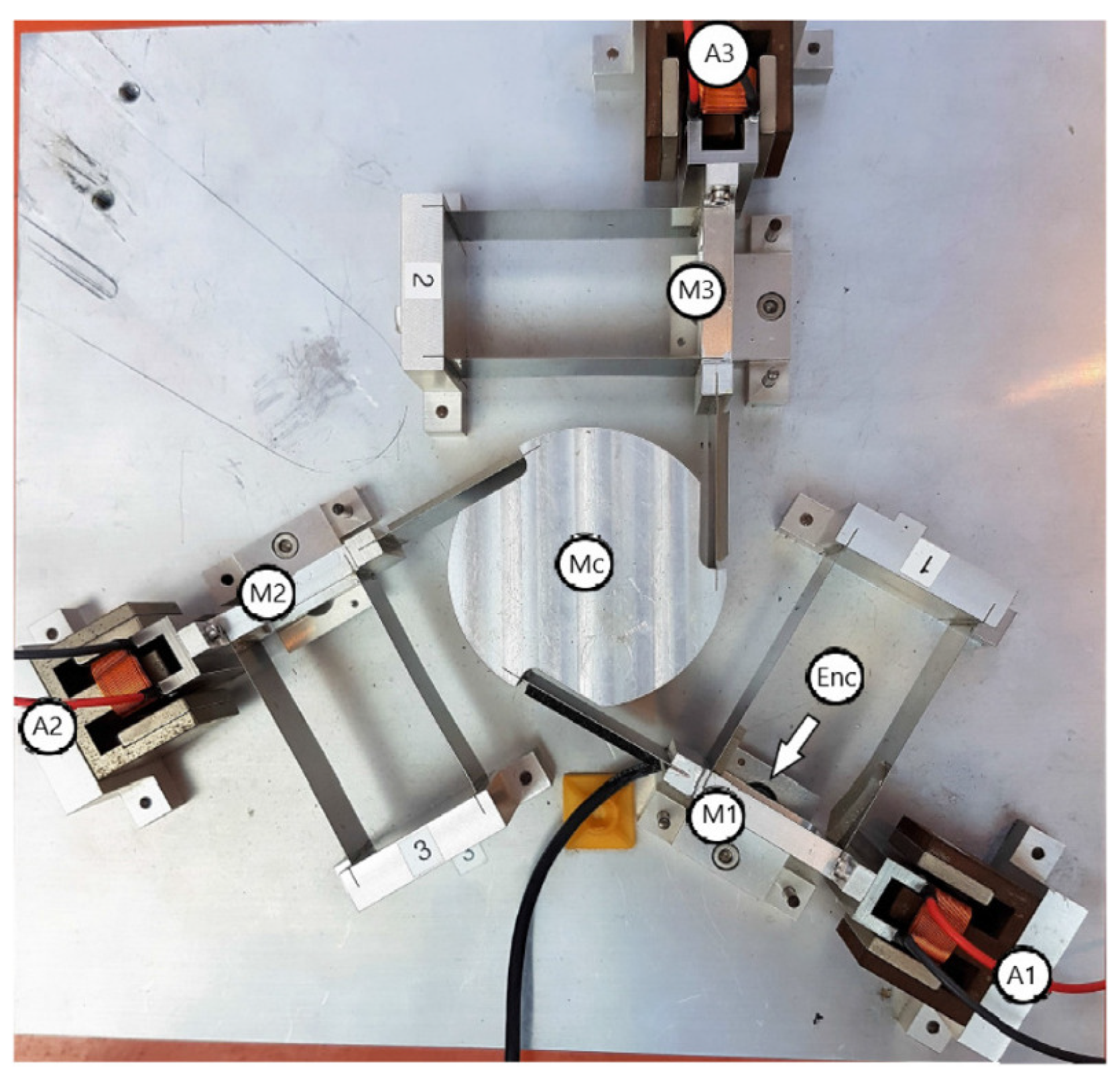
In this section, we demonstrate that fractional-order attenuators can be implemented in practice and that they provide stronger attenuation than comparable integer-order filters. To focus on controller validation, a simple plant is selected. A precision flexure-based positioning stage presented in Figure 8 is used as an experimental setup. This is a planar positioning system, in which two translations and one rotation of the platform (MC) can be controlled. It is achieved by controlling translations of three intermediate elements (M1–M3). Each of the intermediate elements is constrained to allow a single translation by parallel flexures, actuated by a dedicated voice-coil actuator (A1–A3), and its position is measured with an optical encoder.
For the purpose of this experiment, only actuator 1A is used to control the position of the intermediate element M1. The same actuator is used to provide both the disturbance signal and the control force. This results in a SISO system, whose dynamics can are approximated by a transfer function
G ( s ) = 7597 s 2 + 5.914 s + 7138 .
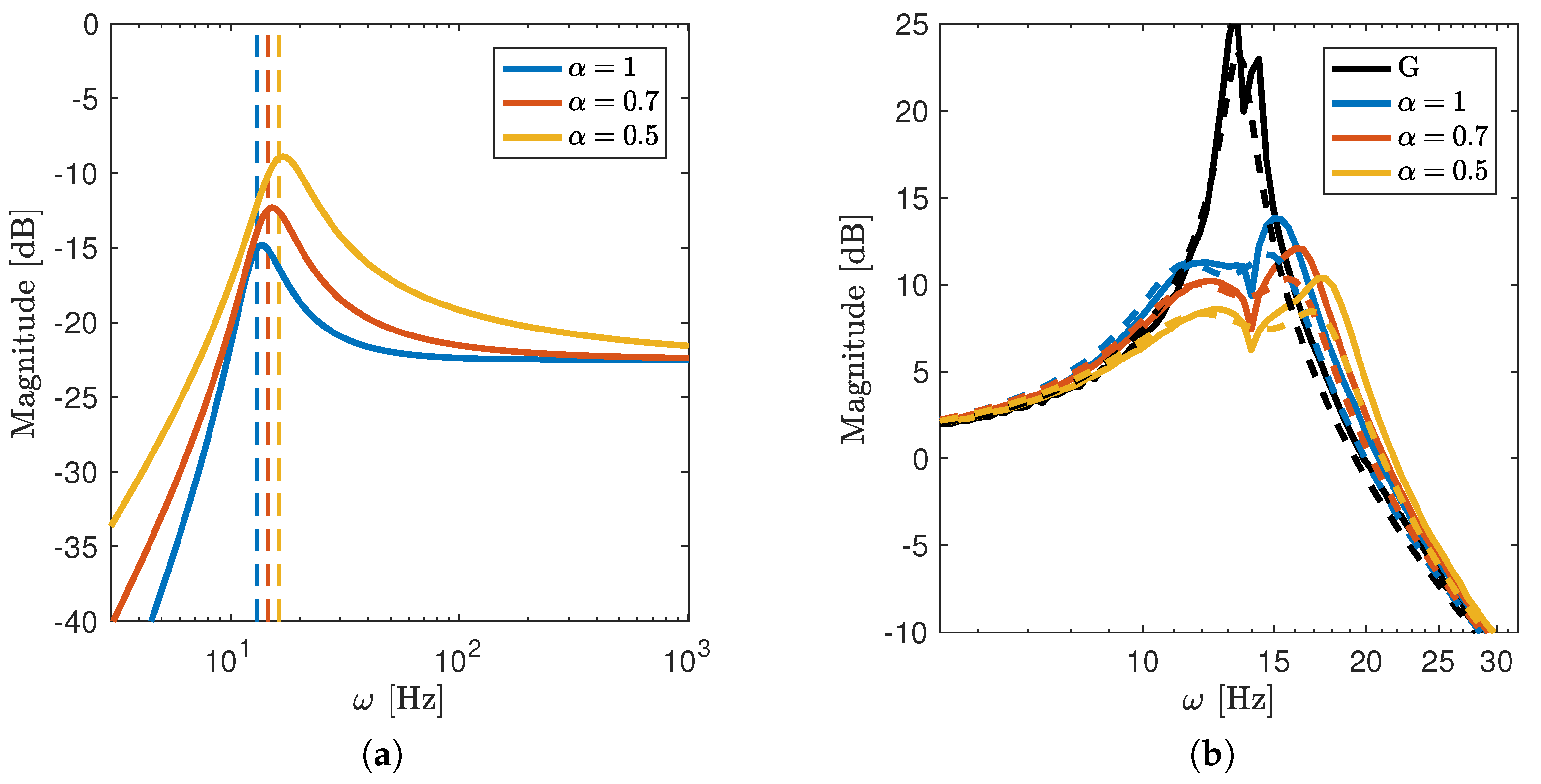
This is equivalent to a mass-spring damper system with ω n = 84.49 rad/s = 13.45 Hz, ζ f = 3.5 × 10 2 and k = 0.9395 . The attenuators are implemented as digital controllers with a sampling time of 0.1 ms. This leads to a time delay of approximately 0.2 ms in the identified plant. The approximated and measured frequency responses of the plant are compared in Figure 9b. In the measured dynamics, two closely placed resonance peaks can be seen, which have been approximated by a single mode in the model. Despite this discrepancy, the controllers designed using the approximated model yield good results when implemented in the actual setup.
To show the benefits of the proposed FO controller, the performance of two FO controllers with different values of α and an integer-order NPF controller were compared experimentally. To guarantee fair comparison for each selected value of α , the gain of all controllers was set to k f = 0.1 , and the remaining controller parameters were chosen with the same optimisation method. The objective of the optimisation problem was set to minimise the H norm of the closed-loop frequency response of the system with the approximated plant (Equation (18)), with the constraint that the closed-loop system must be stable. The obtained parameters are presented in Table 1, and frequency responses of the controllers are shown in Figure 9a. The controllers with orders α < 1 are characterised by higher resonance peaks, which contributes to the stronger attenuation of the resonance in the closed loop. The width of the resonance peaks of the optimally tuned FO controllers increases as α decreases, which may indicate higher robustness of the control system to parameter variation and should be studied in the future.
To enable the implementation, the FO controllers were approximated with integer-order systems. Continuous-time state-space systems of order 8 appeared to be sufficient to achieve a satisfactory approximation of the FO controller in frequencies between 1 and 5000 Hz. The approximations were obtained with the identification-based approach using the desired frequency responses of the FO controllers and Matlab function ssest. All the controllers were discretised using the bilinear (Tustin) method with a sampling time of 0.1 ms and implemented on a real-time FPGA target.
The predicted and measured closed-loop dynamics of the system are shown in Figure 9b. As expected, stronger attenuation of the resonance peak can be achieved with the fractional-order controllers. The maximal magnitudes of the measured frequency response for systems with α = { 1 , 0.7 , 0.5 } are 13.81 dB, 12.11 dB and 10.36 dB, respectively. The differences between the predicted and measured responses are a result of using a simplified model for the plant dynamics.

5. Conclusions

In this paper, we introduced a new FO NPF controller for collocated control systems. The design of the controller was motivated by the frequency-domain loop-shaping analysis, and the controller dynamics have been defined to maintain the high-pass characteristics of an integer-order NPF. The stability and tuning of the proposed controller were analysed, and we demonstrated that the extension of the NPF provides greater design freedom. In particular, lowering the steepness of the magnitude of the frequency response of the controller at low frequencies leads to stronger attenuation of the resonance peak of the plant in the closed loop. The ideal FO controllers were approximated by finite-dimensional integer-order systems, discretised and implemented for damping in an experimental setup. Despite the discrepancy between the assumed dynamics of the plant used for tuning and actual dynamics, the FO controllers provided stronger attenuation than the optimal integer-order one with the same high-frequency gain.

Author Contributions

M.B.K.: conceptualisation, methodology, investigation, formal analysis and writing—original draft preparation; H.H.: conceptualisation, writing—review and editing, supervision and funding acquisition. All authors have read and agreed to the published version of the manuscript.

Funding

This work was supported by the NWO HTSM Applied and Technical Science Program under project MetaMech with number 17976.

Data Availability Statement

Not applicable.

Conflicts of Interest

The authors declare no conflict of interest.

Appendix A. Optimal Tuning of Integer-Order NPF
In this appendix, we briefly present derivations of tuning formulas for controllers with α = 1 . An alternative derivation, including robustness considerations, is presented in [5]. The procedure used for the derivation is based on the fixed-point method, as introduced by Den Hartog for tuning of tuned mass dampers [10].
In the derivations, we consider a single-mode plant (Equation (12)) and the controller (Equation (11)). We assume that the damping in the mechanical system has negligible influence on the tuning parameters and can be ignored in the derivations. To make the formulas more general, relative parameters are introduced. We have then:
G T ( ω ) = 1 / k ( j ω / Ω ) 2 + 1 = 1 / k g 2 + 1
H 2 ( ω ) = k f ( j ω / ω f ) 2 α ( j ω / ω f ) 2 α + 2 ζ f ( j ω / ω f ) α + 1 = k f ( j g / f ) 2 α ( j g / f ) 2 α + 2 ζ f ( j g / f ) α + 1
with the relative frequency g = ω / ω n and corner frequency shift f = ω f / ω n . The open-loop gain K = k f / k is also used in further derivations.
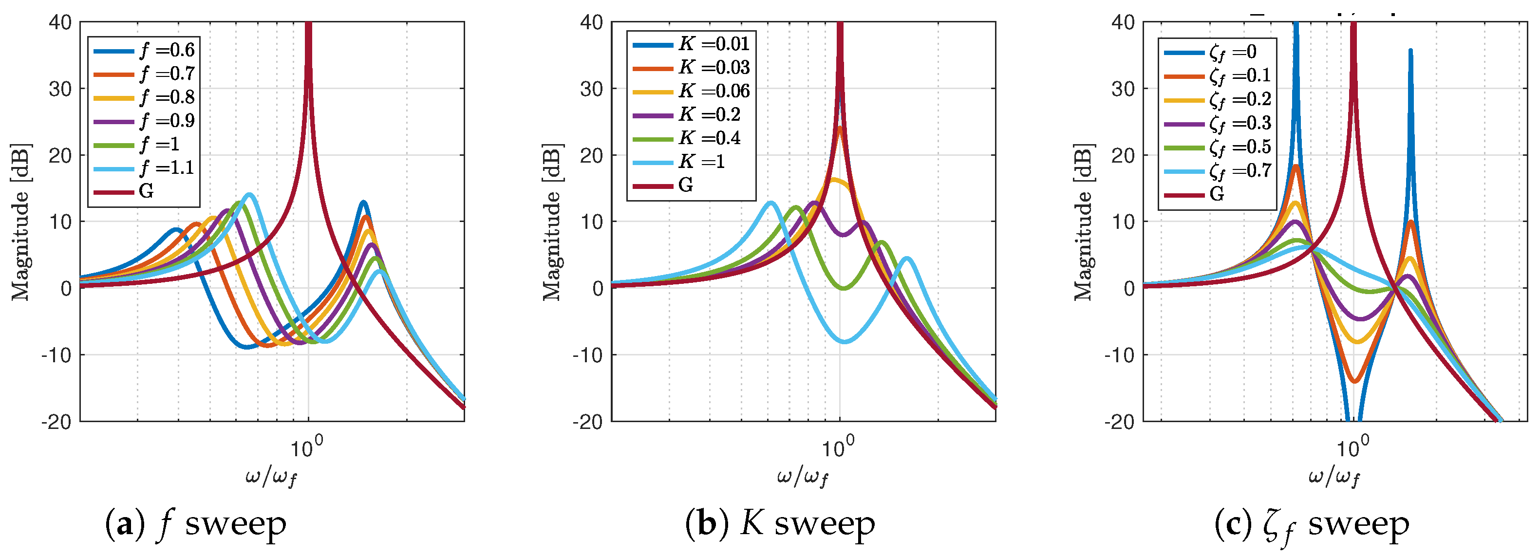
The closed-loop response of a single-mode system is presented in Figure A1. Points independent of the damping ratio ζ f , as shown in Figure A1c, are used to derive the tuning formulas. First, we find the frequencies g α = 1 * of the fixed points. Next, we select f α = 1 * such that the magnitudes of the fixed points are the same. Finally, ζ f , α = 1 * is chosen to obtain a flat response.
Figure A1. Influence of the tuning parameters on the closed-loop frequency response of a single-mode system with FracNPF with α = 1 .
Fractalfract 07 00222 g0a1
The closed-loop frequency response of the system with α = is given by
T α = 1 = G 1 + G H 2 = 1 / k ( 1 + 2 ζ f g j / f g 2 / f 2 ) g 4 / f 2 ( f 2 + K + 1 ) g 2 / f 2 + 2 ζ f ( g 3 / f + g / f ) j + 1 ,
and the magnitude of the response is
| T α = 1 | 2 = 1 / k 2 ( f 4 + 4 f 2 g 2 ζ f 2 2 f 2 g 2 + g 4 ) ( K g 2 f 2 + g 2 g 4 + f 2 g 2 ) 2 + 4 ζ f 2 f 2 ( g 3 + g ) 2 .
To find the frequency at which the magnitude of the response is independent of ζ f , the numerator and denominator of | T α = 1 | 2 are expressed as polynomials in ζ , i.e., | T α = 1 | 2 = ( n 1 ζ f 2 + n 2 ) / ( d 1 ζ f 2 + d 2 ) , n 1 , n 2 , d 1 , d 2 R . The magnitude of the response is independent of ζ f at frequencies g where the ratios of corresponding terms of the polynomials are equal, i.e., n 1 / d 1 = n 2 / d 2 . This is the case for
g α = 1 * = 1 2 K + 2 f 2 + 2 ± ( ( 2 f 2 4 f + K + 2 ) ( 2 f 2 + 4 f + K + 2 ) ) 1 / 2 1 / 2 .
The magnitude at the fixed points is independent of ζ f . To find this magnitude, we can select the most convenient ζ f . By taking ζ f = , we obtain
| T α = 1 * | 2 = 1 / k 1 g α = 1 * 2 2 .
By substituting g α = 1 * and requiring the magnitudes of the closed-loop response at both fixed points to be equal, we obtain
f α = 1 * = 2 / 2 2 K .
The optimal value of damping should provide a flat magnitude of the closed-loop response near the frequency of the target mode. This goal can be achieved by requiring that the magnitude of the response at the fixed points g α = 1 * and at the target frequency g = 1 are identical. This is the case for damping ratio
ζ f , α = 1 * = 2 4 K ( 8 K ) 2 K .
The quality factor of the system with α = 1 can be estimated using the magnitude of the response at the fixed points as
Q α = 1 * k | T α = 1 * | = 2 / K .

References

  1. Preumont, A. Vibration Control of Active Structures, Solid Mechanics and Its Applications, 4th ed.; Springer International Publishing: Cham, Switzerland, 2018; Volume 246. [Google Scholar] [CrossRef]
  2. Balas, M.J. Direct Velocity Feedback Control of Large Space Structures. J. Guid. Control 1979, 2, 252–253. [Google Scholar] [CrossRef]
  3. Kim, S.M.; Wang, S.; Brennan, M.J. Optimal and robust modal control of a flexible structure using an active dynamic vibration absorber. Smart Mater. Struct. 2011, 20, 045003. [Google Scholar] [CrossRef]
  4. Kim, S.M.; Wang, S.; Brennan, M.J. Dynamic analysis and optimal design of a passive and an active piezo-electrical dynamic vibration absorber. J. Sound Vib. 2011, 330, 603–614. [Google Scholar] [CrossRef]
  5. Kim, S.M.; Wang, S.; Brennan, M.J. Comparison of negative and positive position feedback control of a flexible structure. Smart Mater. Struct. 2011, 20, 015011. [Google Scholar] [CrossRef]
  6. Kim, S.M.; Brennan, M.J.; Abreu, G.L. Narrowband feedback for narrowband control of resonant and non-resonant vibration. Mech. Syst. Signal Process. 2016, 76, 47–57. [Google Scholar] [CrossRef] [Green Version]
  7. Cazzulani, G.; Resta, F.; Ripamonti, F.; Zanzi, R. Negative derivative feedback for vibration control of flexible structures. Smart Mater. Struct. 2012, 21, 075024. [Google Scholar] [CrossRef]
  8. Syed, H.H. Comparative study between positive position feedback and negative derivative feedback for vibration control of a flexible arm featuring piezoelectric actuator. Int. J. Adv. Robot. Syst. 2017, 14, 1729881417718801. [Google Scholar] [CrossRef] [Green Version]
  9. Goh, C.J.; Caughey, T.K. On the stability problem caused by finite actuator dynamics in the collocated control of large space structures. Int. J. Control 1985, 41, 787–802. [Google Scholar] [CrossRef]
  10. Den Hartog, J.P. Mechanical Vibrations; McGraw-Hill Book Company, Inc.: New York, NY, USA, 1940. [Google Scholar]
  11. Caponetto, R.; Dongola, G.; Fortuna, L.; Petráš, I. Fractional Order Systems: Modeling and Control Applications; World Scientific Publishing Co.: Singapore, 2010; pp. 1–178. [Google Scholar] [CrossRef]
  12. Meral, M.E.; Çelík, D. A comprehensive survey on control strategies of distributed generation power systems under normal and abnormal conditions. Annu. Rev. Control 2019, 47, 112–132. [Google Scholar] [CrossRef]
  13. Singh, P.P.; Roy, B.K. Comparative performances of synchronisation between different classes of chaotic systems using three control techniques. Annu. Rev. Control 2018, 45, 152–165. [Google Scholar] [CrossRef]
  14. Cao, K.; Chen, Y.; Stuart, D. A fractional micro-macro model for crowds of pedestrians based on fractional mean field games. IEEE/CAA J. Autom. Sin. 2016, 3, 261–270. [Google Scholar] [CrossRef] [Green Version]
  15. Ge, F.; Chen, Y.; Kou, C. Cyber-physical systems as general distributed parameter systems: Three types of time-series models and emerging research opportunities. IEEE/CAA J. Autom. Sin. 2015, 2, 353–357. [Google Scholar] [CrossRef] [Green Version]
  16. Adolfsson, K.; Enelund, M.; Olsson, P. On the fractional order model of viscoelasticity. Mech. Time Depend. Mater. 2005, 9, 15–34. [Google Scholar] [CrossRef]
  17. Bonfanti, A.; Kaplan, J.L.; Charras, G.; Kabla, A. Fractional viscoelastic models for power-law materials. Soft Matter 2020, 16, 6002–6020. [Google Scholar] [CrossRef] [PubMed]
  18. Chen, Y.Q. Ubiquitous fractional order controls? In Proceedings of the IFAC Proceedings Volumes (IFAC-PapersOnline); Elsevier: Amsterdam, The Netherlands, 2006; Volume 2, pp. 481–492. [Google Scholar] [CrossRef] [Green Version]
  19. Chen, Y.Q.; Petráš, I.; Xue, D. Fractional order control—A tutorial. In Proceedings of the American Control Conference, St. Louis, Mo, USA, 10–12 June 2009; pp. 1397–1411. [Google Scholar] [CrossRef]
  20. Dastjerdi, A.A.; Saikumar, N.; HosseinNia, S.H. Tuning guidelines for fractional order PID controllers: Rules of thumb. Mechatronics 2018, 56, 26–36. [Google Scholar] [CrossRef]
  21. Dastjerdi, A.A.; Vinagre, B.M.; Chen, Y.Q.; HosseinNia, S.H. Linear fractional order controllers; A survey in the frequency domain. Annu. Rev. Control 2019, 47, 51–70. [Google Scholar] [CrossRef]
  22. San-Millan, A.; Feliu-Batlle, V.; Aphale, S.S. Application of a Fractional Order Integral Resonant Control to increase the achievable bandwidth of a nanopositioner. IFAC PapersOnLine 2017, 50, 14539–14544. [Google Scholar] [CrossRef] [Green Version]
  23. Marinangeli, L.; Alijani, F.; Hosseinnia, S.H. Fractional-order positive position feedback compensator for active vibration control of a smart composite plate. J. Sound Vib. 2018, 412, 1–16. [Google Scholar] [CrossRef]
  24. Niu, W.; Li, B.; Xin, T.; Wang, W. Vibration active control of structure with parameter perturbation using fractional order positive position feedback controller. J. Sound Vib. 2018, 430, 101–114. [Google Scholar] [CrossRef]
  25. Feliu-Talegon, D.; San-Millan, A.; Feliu-Batlle, V. Fractional-order integral resonant control of collocated smart structures. Control. Eng. Pract. 2016, 56, 210–223. [Google Scholar] [CrossRef]
  26. Wang, Z.H.; Zheng, Y.G. The optimal form of the fractional-order difference feedbacks in enhancing the stability of a sdof vibration system. J. Sound Vib. 2009, 326, 476–488. [Google Scholar] [CrossRef]
  27. Radwan, A.G.; Elwakil, A.S.; Soliman, A.M. On the generalization of second-order filters to the fractional-order domain. J. Circuits Syst. Comput. 2009, 18, 361–386. [Google Scholar] [CrossRef]
  28. Malti, R.; Moreau, X.; Khemane, F.; Oustaloup, A. Stability and resonance conditions of elementary fractional transfer functions. Automatica 2011, 47, 2462–2467. [Google Scholar] [CrossRef]
  29. Ivanova, E.; Moreau, X.; Malti, R. Stability and resonance conditions of second-order fractional systems. J. Vib. Control 2018, 24, 659–672. [Google Scholar] [CrossRef]
  30. Zhang, S.; Liu, L.; Xue, D.; Chen, Y.Q. Stability and resonance analysis of a general non-commensurate elementary fractional-order system. Fract. Calc. Appl. Anal. 2020, 23, 183–210. [Google Scholar] [CrossRef]
  31. Sahoo, S.; Saha Ray, S.; Das, S. An efficient and novel technique for solving continuously variable fractional order mass-spring-damping system. Eng. Comput. 2017, 34, 2815–2835. [Google Scholar] [CrossRef]
  32. Sene, N.; Aguilar, J.F.G. Fractional mass-spring-damper system described by generalized fractional order derivatives. Fractal Fract. 2019, 3, 39. [Google Scholar] [CrossRef] [Green Version]
  33. Pang, D.; Jiang, W.; Liu, S.; Jun, D. Stability analysis for a single degree of freedom fractional oscillator. Phys. A Stat. Mech. Its Appl. 2019, 523, 498–506. [Google Scholar] [CrossRef]
  34. Adhikary, A.; Sen, S.; Biswas, K. Practical Realization of Tunable Fractional Order Parallel Resonator and Fractional Order Filters. IEEE Trans. Circuits Syst. I Regul. Pap. 2016, 63, 1142–1151. [Google Scholar] [CrossRef]
  35. Tsirimokou, G.; Psychalinos, C.; Elwakil, A.S.; Salama, K.N. Electronically Tunable Fully Integrated Fractional-Order Resonator. IEEE Trans. Circuits Syst. II Express Briefs 2018, 65, 166–170. [Google Scholar] [CrossRef] [Green Version]
  36. Kapoulea, S.; Psychalinos, C.; Elwakil, A.S. Power law filters: A new class of fractional-order filters without a fractional-order Laplacian operator. AEU Int. J. Electron. Commun. 2021, 129, 153537. [Google Scholar] [CrossRef]
  37. Mahata, S.; Herencsar, N.; Kubanek, D. On the design of power law filters and their inverse counterparts. Fractal Fract. 2021, 5, 197. [Google Scholar] [CrossRef]
  38. Sethi, V.; Franchek, M.A.; Song, G. Multimodal active vibration suppression of a flexible structure by loop shaping. In Smart Structures and Materials 2005: Smart Structures and Integrated Systems; SPIE: New York, NY, USA, 2005; Volume 5764, p. 348. [Google Scholar] [CrossRef]
  39. Sethi, V.; Song, G.; Franchek, M.A. Loop shaping control of a model-story building using smart materials. J. Intell. Mater. Syst. Struct. 2008, 19, 765–777. [Google Scholar] [CrossRef]
  40. Munoa, J.; Beudaert, X.; Erkorkmaz, K.; Iglesias, A.; Barrios, A.; Zatarain, M. Active suppression of structural chatter vibrations using machine drives and accelerometers. CIRP Ann. Manuf. Technol. 2015, 64, 385–388. [Google Scholar] [CrossRef]
  41. Monje, C.A.; Chen, Y.Q.; Vinagre, B.M.; Xue, D.; Feliu, V. Fractional-Order Systems and Controls, Fundamentals and Applications; Springer: London, UK, 2010. [Google Scholar] [CrossRef]
  42. Matignon, D. Stability properties for generalized fractional differential systems. ESAIM Proc. 1998, 5, 145–158. [Google Scholar] [CrossRef] [Green Version]
  43. Åström, K.J. Limitations on control system performance. In Proceedings of the ECC 1997—European Control Conference; Institute of Electrical and Electronics Engineers Inc.: Piscataway, NJ, USA, 1997; pp. 3421–3426. [Google Scholar] [CrossRef]
  44. Vinagre, B.; Podlubny, I.; Hernandez, A.; Feliu, V. Some Approximations of Fractional Order Operators Used in Control Theory and Applications. Fract. Calc. Appl. Anal. 2000, 3, 231–248. [Google Scholar]
  45. Oustaloup, A. Systemes Asservis Lineaires D’ordre Fractionnaire: Theorie et Pratique; Masson: Paris, France, 1983; p. 296. [Google Scholar]
  46. Schmidt, R.M.; Schitter, G.; Rankers, A.; van Eijk, J. The Design of High Performance Mechatronics, 2nd ed.; IOS Press: Amsterdam, The Netherlands, 2014. [Google Scholar]
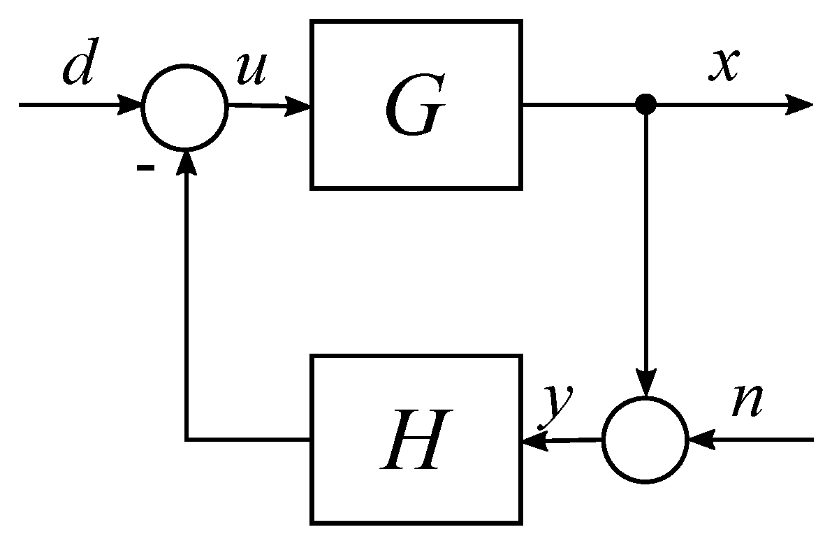
Figure 1. Control structure. Adapted from [4].
Fractalfract 07 00222 g001
Figure 2. Illustration of the concept of loop-shaping. Using the knowledge of uncontrolled G and desired dynamics T, the necessary shapes of sensitivity S, loop gain G H and controllers can be deduced. H 1 denotes VF, while H 2 denotes NPF. Both lead to different slopes of G H .
Fractalfract 07 00222 g002
Figure 3. Frequency responses of a fractional-order attenuator with ζ f = 0 (a) and marginally stable fractional-order attenuators (b) for different values of α . All other parameters are constant.
Fractalfract 07 00222 g003
Figure 4. Sensitivity function S (a) and closed-loop frequency response T (b) for a lightly damped plant and marginally stable fractional-order attenuators with different α . All other parameters are constant, ω f = ω n .
Fractalfract 07 00222 g004
Figure 5. Closed-loop frequency response T for a lightly damped plant and fractional-order attenuators with (a) ζ f , α = 1 = 0.2 , (b) ζ f , α = 1 = 0.4 and different α . Values of ω f are adjusted for maximal attenuation.
Fractalfract 07 00222 g005
Figure 6. Frequency responses of optimal fractional-order attenuators with ζ f , α = 1 = 0.2 . Dashed lines indicate the corner frequencies ω f of attenuators with corresponding α .
Fractalfract 07 00222 g006
Figure 7. Optimal quality factor and tuning parameters for a single-mode plant with an FO NPF controller.
Fractalfract 07 00222 g007
Figure 8. Planar precision positioning stage with voice-coil actuators denoted as A1, A2 and A3 controlling the three masses (indicated as M1, M2 and M3) and constrained by leaf flexures. The central mass (indicated by Mc) is connected to these 3 masses through leaf flexures and linear encoders (indicated by Enc) placed under masses M1, M2 and M3 to provide position feedback.
Fractalfract 07 00222 g008
Figure 9. Implemented controllers (a) and compassion of frequency responses (b) obtained from experiments. Dashed (–) and solid (-) lines in (b) present the predicted and measured responses, respectively.
Fractalfract 07 00222 g009
Table 1. Tuning parameters of implemented fractional-order controllers.
H 1 H 2 H 3
k f 0.1 0.1 0.1
α 1 0.7 0.5
ζ f 0.2116 0.2974 0.6016
ω n / ω f 0.9565 1.0690 1.1954
Disclaimer/Publisher’s Note: The statements, opinions and data contained in all publications are solely those of the individual author(s) and contributor(s) and not of MDPI and/or the editor(s). MDPI and/or the editor(s) disclaim responsibility for any injury to people or property resulting from any ideas, methods, instructions or products referred to in the content.