
Map of a Bending Problem for Self-Similar Beams into the Fractal Continuum Using the Euler–Bernoulli Principle


Abstract
:1. Introduction
2. Fractal Aspects
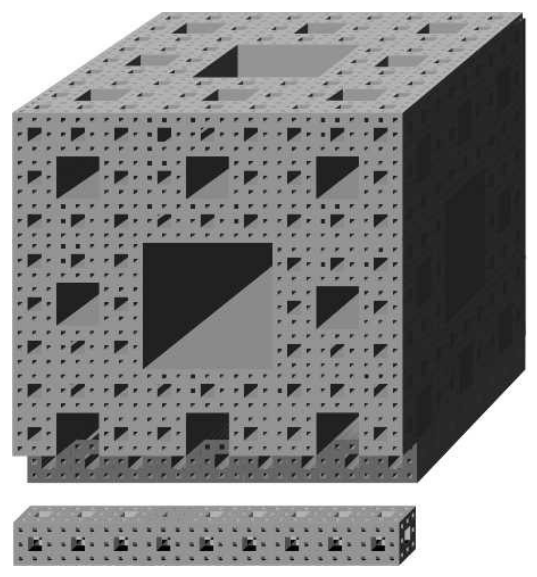
2.1. Fractal Domain
2.2. Fractal Continuum Domain
2.3. Elastic Fractal Continuum
3. Differential Equations of the Euler–Bernoulli Beam in the Continuum
3.1. Euler–Bernoulli Beam Equation in Fractal Continuum
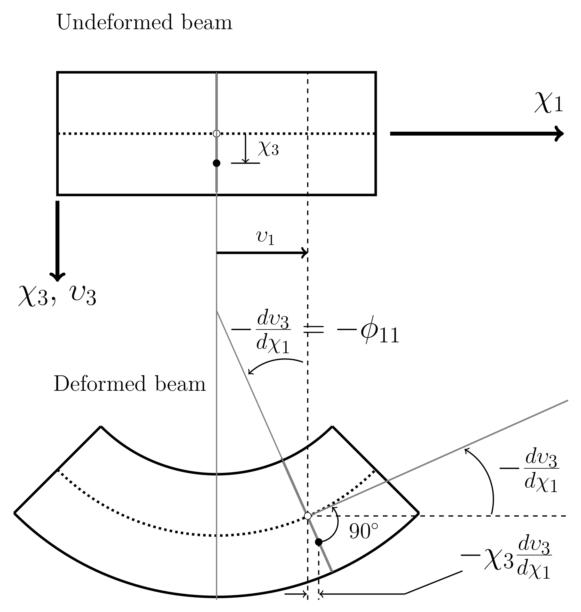
3.2. Continuum for Rotation , Bending Moment and Shear Force of Self-Similar Beams
4. Bending on a Cantilever Fractal Beam
4.1. Structural Behavior
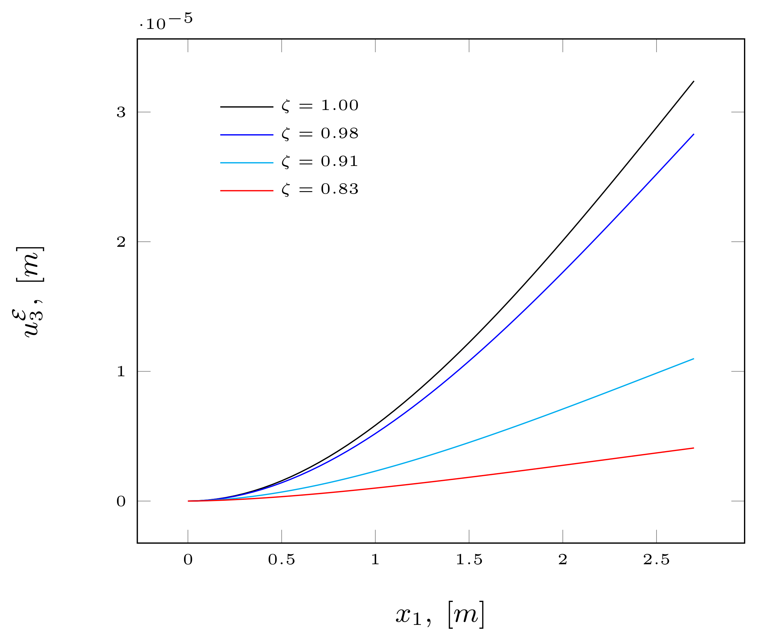
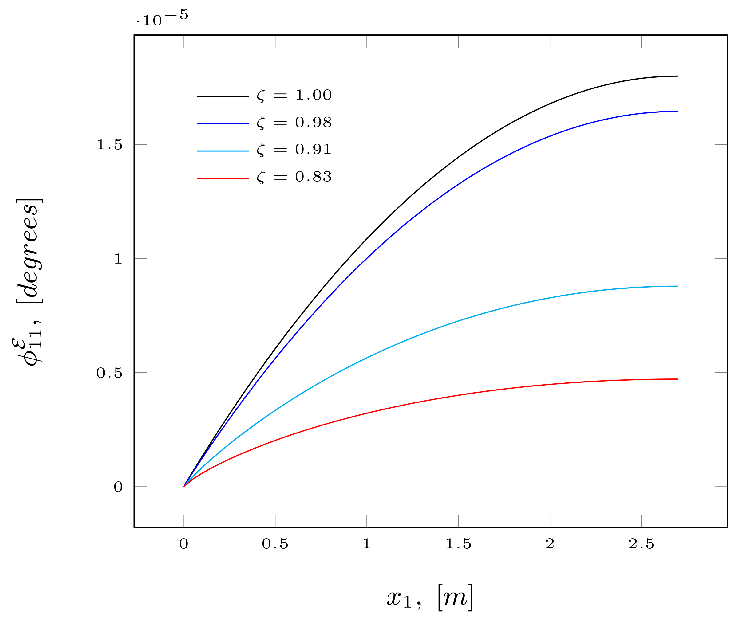
4.2. Discussion of Results Obtained
5. Conclusions
- i
- Parameters , , and control the stiffness of the fractal beam;
- ii
- The bending stiffness is influenced by the fractal geometry of the beam, specifically, by the cross-section area along its length, so that it increases as its co-dimension decreases according to Equation (33);
- iii
- The scale effect depends on boundary conditions, fractal mass of the pre-fractals and the length scales of similarity;
- iv
- The fractal continuum model allows the exact solutions to be obtained, subject to the values of order ;
- v
- The solution to the classical model is obtained when ;
- vi
- vii
- The model can be extended to describe the structural dynamic behavior of fractal beams, such as free vibration and modal analysis.
Author Contributions
Funding
Institutional Review Board Statement
Informed Consent Statement
Data Availability Statement
Acknowledgments
Conflicts of Interest
References
- Yu, T.X.; Zhang, L.C. Plastic Bending: Theory and Applications; World Scientific Publishing Co Pte Ltd.: Singapore, 1996; pp. 7–164. [Google Scholar]
- Sofi, A.; Muscolino, G. Static analysis of euler-benoulli beams with interval youngs modulus. Comput. Struct. 2015, 156, 72–82. [Google Scholar] [CrossRef]
- Cicirello, A.; Palmeri, A. Static analysis of euler-bernoulli beams with multiple unilateral cracks under combined axial and transverse loads. Int. J. Solids Struct. 2014, 51, 1020–1029. [Google Scholar] [CrossRef] [Green Version]
- Di-Paola, M.; Heuer, R.; Pirrota, A. Fractional visco-elastic Euler-Bernoulli beam. Int. J. Solids Struct. 2013, 50, 3505–3510. [Google Scholar] [CrossRef] [Green Version]
- Cicirello, A. On the response bounds of damaged Euler-Bernoulli beams with switching cracks under moving masses. Int. J. Solids Struct. 2019, 172, 70–83. [Google Scholar] [CrossRef]
- Palmeri, A.; Cicirello, A. Physically-based diracs delta functions in the static analysis of multi-cracked Euler-Bernoulli and Timoshenko beams. Int. J. Solids Struct. 2011, 48, 2184–2195. [Google Scholar] [CrossRef] [Green Version]
- Olson, G.; Hatton, R.; Adams, J.; Menguc, Y. An Euler-Bernoulli beam model for soft robot arms bent through self-stress and external loads. Int. J. Solids Struct. 2020, 207, 113–131. [Google Scholar] [CrossRef]
- Yang, B. Stress, Strain and Structural Dynamics; Elsevier: San Diego, CA, USA, 2005; pp. 9–55. [Google Scholar]
- Balankin, A.S. Fractional space approach to studies of physical phenomena on fractals and in confined low-dimensional systems. Chaos Solitons Fractals 2020, 132, 109572. [Google Scholar] [CrossRef]
- Golmankhaneh, A.K.; Welch, K. Equilibrium and non-equilibrium statistical mechanics with generalized fractal derivatives: A review. Mod. Phys. Lett. A 2021, 14, 2140002. [Google Scholar] [CrossRef]
- Gowrisankar, A.; Golmankhaneh, A.K.; Serpa, C. Fractal calculus on fractal interpolation functions. Fractal Fract. 2021, 5, 157. [Google Scholar] [CrossRef]
- Pishkoo, A.; Darus, M. Using fractal calculus to solve fractal Navier–Stokes equations, and simulation of laminar static mixing in COMSOL multiphysics. Fractal Fract. 2021, 5, 16. [Google Scholar] [CrossRef]
- Golmankhaneh, A.; Tunc, C. Analogues to Lie Method and Noether’s Theorem in Fractal Calculus. Fractal Fract. 2019, 3, 25. [Google Scholar] [CrossRef] [Green Version]
- Balankin, A.S. A continuum framework for mechanics of fractal materials I: From fractional space to continuum with fractal metric. Eur. J. Phys. B 2015, 88, 90. [Google Scholar] [CrossRef]
- Lacan, F.; Tresser, C. Fractal as object with nontrivial structures at all scales. Chaos Solitons Fractals 2015, 75, 218–242. [Google Scholar] [CrossRef]
- Xiao, J.; Long, X.; Jiang, H.; Zhang, Y.; Qu, W. Study on the influence of three factors on mass loss and surface fractal dimension of concrete in sulfuric acid environments. Fractal Fract. 2021, 5, 146. [Google Scholar] [CrossRef]
- Parvate, A.; Seema, S.; Gangal, A.D. Calculus on fractal curves in Rn. Fractals 2011, 10, 15–27. [Google Scholar] [CrossRef] [Green Version]
- Tarasov, V.E. General Fractional Vector Calculus. Mathematics 2021, 9, 2816. [Google Scholar] [CrossRef]
- Sumelka, W. Thermoelasticity in the framework of the fractional continuum mechanics. J. Therm. Stress. 2014, 37, 678–706. [Google Scholar] [CrossRef]
- Li, J.; Ostoja-Starzewski, M. Fractal solids, product measures and fractional wave equations. Proc. R. Soc. A Math. Phys. 2009, 465, 2521–2536. [Google Scholar] [CrossRef]
- Li, J.; Ostoja-Starzewski, M.; Li, J.; Joumaa, H.; Demmie, P.N. From fractal media to continuum mechanics. Math. Mech. 2009, 94, 373–401. [Google Scholar] [CrossRef]
- Davey, K.; Rasgado, A. Analytical solutions for vibrating fractal composite rods and beams. Appl. Math. Model. 2011, 35, 1194–1209. [Google Scholar] [CrossRef]
- Lazopoulos, K.A.; Lazopoulos, A.K. On fractional bending of beams. Arch. Appl. Mech. 2016, 86, 1133–1145. [Google Scholar] [CrossRef]
- Lazopoulos, K.A.; Lazopoulos, A.K. On fractional bending of beams with Λ-fractional derivative. Arch. Appl. Mech. 2020, 90, 573–584. [Google Scholar] [CrossRef]
- Blaszczyk, T. Analytical and numerical solution of the fractional Euler-Bernoulli beam equation. J. Mech. Mater. Struct. 2017, 12, 23–34. [Google Scholar] [CrossRef]
- Sumelka, W.; Blaszczyk, T.; Liebold, C. Fractional Euler-Bernoulli beams: Theory, numerical study and experimental validation. Eur. J. Mech. A/Solids 2015, 54, 243–251. [Google Scholar] [CrossRef] [Green Version]
- Stempin, P.; Sumelka, W. Space-fractional Euler-Bernoulli beam model Theory and identification for silver nanobeam bending. Int. J. Mech. Sci. 2020, 186, 105902. [Google Scholar] [CrossRef]
- Stempin, P.; Sumelka, W. Formulation and experimental validation of space-fractional Timoshenko beam model with fucntionally graded materials effects. Comput. Mech. 2021, 68, 697–708. [Google Scholar] [CrossRef]
- Sumelka, W. On fractional non-local bodies with variable length scale. Mech. Res. Commun. 2017, 86, 5–10. [Google Scholar] [CrossRef]
- Szajek, K.; Sumelka, W. Discrete mass-spring structure identification in non-local continuum space-fractional model. Eur. Phys. J. Plus 2019, 134, 444. [Google Scholar] [CrossRef] [Green Version]
- Rayneau-Kirkhope, D.; Mao, Y.; Farr, R. Optimisation of fractal spaceframes under gentle compressive load. Phys. Rev. E 2013, 87, 063204. [Google Scholar] [CrossRef] [Green Version]
- Zhang, X.; Yang, F.; Liu, B.; Deng, J. Design of menger sponge fractal structural NiTi as bone implants. Model. Simul. Mater. Sci. Eng. 2021, 29, 084001. [Google Scholar] [CrossRef]
- Carpinteri, A.; Pugno, N.; Sapora, A. Dynamic response of damped von Koch antennas. J. Vib. Control 2009, 17, 733–740. [Google Scholar] [CrossRef]
- Balankin, A.S. Stresses and strain in a deformable fractal medium and in its fractal continuum model. Phys. Lett. A 2013, 377, 2535–2541. [Google Scholar] [CrossRef]
- Balankin, A.S.; Elizarraraz, B.E. Hydrodynamics of fractal continuum flow. Phys. Rev. E 2012, 85, 025302(R). [Google Scholar] [CrossRef] [PubMed]
- Balankin, A.S.; Elizarraraz, B.E. Map of fluid flow in fractal porous medium into fractal continuum flow. Phys. Rev. E 2012, 85, 056314. [Google Scholar] [CrossRef] [PubMed]
- Balankin, A.S.; Mena, B.; Patino, J.; Morales, D. Electromagnetic fields in fractal continuum. Phys. Lett. A 2013, 377, 783–788. [Google Scholar] [CrossRef]
- Balankin, A.S. The topological hausdorff dimension and transport properties of sierpinski carpet. Phys. Lett. A 2017, 381, 2801–2808. [Google Scholar] [CrossRef]
- Cristea, L.L.; Steinky, B. Connected generalised sierpinski carpets. Topol. Appl. 2010, 157, 1157–1162. [Google Scholar] [CrossRef] [Green Version]
- Ullah, A.S.; Dáddona, D.M.; Seto, Y.; Yonehara, S.; Kubo, A. Utilizing Fractals for Modeling and 3D Printing of Porous Structures. Fractal Fract. 2021, 5, 40. [Google Scholar] [CrossRef]
- Mabrouk, A.; Selmi, B. On the topological billingsley dimension of self-similar sierpinski carpet. Eur. Phys. J. Spec. Top. 2021, 230, 3861–3871. [Google Scholar] [CrossRef]
- Balankin, A.S.; Patino-Ortiz, J.; Patino-Ortiz, M. Inherent features of fractal sets and key attributes of fractal models. Fractals 2022, in press. [Google Scholar] [CrossRef]
- Balankin, A.S.; Susarrey, O.; García, R.; Morales, L.; Samayoa, D.; López, J.A. Intrinsically anomalous roughness of admissible crack traces in concrete. Phys. Rev. E 2005, 72, 065101(R). [Google Scholar] [CrossRef] [Green Version]
- Damián-Adame, L. Kryvko, A.; Samayoa, D.; Rodríguez, C. An estimation method of fractal dimension of self-avoiding roughened interfaces. Rev. Mex. Física 2017, 63, 12–18. [Google Scholar]
- Falconer, K. Fractal Geometry: Mathematical Foundations and Applications; John Wiley and Sons: Chichester, UK, 2014. [Google Scholar]
- Tarasov, V.E. Continuum medium model for fractal media. Phys. Lett. A 2005, 336, 167–174. [Google Scholar] [CrossRef] [Green Version]
- Ben-Avraham, D.; Havlin, S. Diffusion and Reactions in Fractal and Disordered Systems; Cambridge University Press: Cambridge, UK, 2002. [Google Scholar]
- Samayoa, D.; Ochoa-Ontiveros, L.A.; Damián-Adame, L.; Reyes de Luna, E.; Alvarez-Romero, L.; Romero-Paredes, G. Fractal model equation for spontaneous imbibition. Rev. Mex. Física 2020, 66, 283–290. [Google Scholar] [CrossRef]
- Tunc, C.; Golmankhaneh, A. On stability of a class of second alpha-order fractal differential equations. AIMS Math. 2020, 5, 2126–2142. [Google Scholar] [CrossRef]
- Chen, W. Time-space frabric underlying anomalous diffusion. Chaos Soliton Fractals 2006, 28, 923–929. [Google Scholar] [CrossRef] [Green Version]
- Wang, C.M.; Reddy, J.N.; Lee, K.H. Shear Deformable Beam and Plates; Elsevier: Oxford, UK, 2000. [Google Scholar]
- Moaveni, S. Finite Element Analysis: Theory and Applications with Ansys; Pearson, CPI Group (UK) Ltd.: Croydon, UK, 2015. [Google Scholar]
- Golmankhaneh, A.; Fernandez, A. Fractal Calculus of Functions on Cantor Tartan Spaces. Fractal Fract. 2018, 2, 30. [Google Scholar] [CrossRef] [Green Version]
- Balankin, A.; Golmankhaneh, A.; Patino, J.; Patino, M. Noteworthy fractal features and transport properties of Cantor tartans. Phys. Lett. A 2018, 382, 1534–1539. [Google Scholar] [CrossRef]
- Golmankhaneh, A.; Nia, S.M. Laplace equations on the fractal cubes and Casimir effect. Eur. Phys. J. Spec. Top. 2021, 230, 3895–3900. [Google Scholar] [CrossRef]
- Vicsek, T. Fractal Growth Phenomena; World Scientific: London, UK, 1992. [Google Scholar]


| Parameter | ||||
|---|---|---|---|---|
| 3 | 2.98 | 2.86 | 2.72 | |
| 2 | 1.99 | 1.94 | 1.89 | |
| 1 | 0.98 | 0.91 | 0.83 | |
| 0 | ||||
| 2.70 | 2.58 | 1.87 | 1.30 | |
| I |
Publisher’s Note: MDPI stays neutral with regard to jurisdictional claims in published maps and institutional affiliations. |
© 2022 by the authors. Licensee MDPI, Basel, Switzerland. This article is an open access article distributed under the terms and conditions of the Creative Commons Attribution (CC BY) license (https://creativecommons.org/licenses/by/4.0/).
Share and Cite
Samayoa Ochoa, D.; Damián Adame, L.; Kryvko, A. Map of a Bending Problem for Self-Similar Beams into the Fractal Continuum Using the Euler–Bernoulli Principle. Fractal Fract. 2022, 6, 230. https://doi.org/10.3390/fractalfract6050230
Samayoa Ochoa D, Damián Adame L, Kryvko A. Map of a Bending Problem for Self-Similar Beams into the Fractal Continuum Using the Euler–Bernoulli Principle. Fractal and Fractional. 2022; 6(5):230. https://doi.org/10.3390/fractalfract6050230
Chicago/Turabian StyleSamayoa Ochoa, Didier, Lucero Damián Adame, and Andriy Kryvko. 2022. "Map of a Bending Problem for Self-Similar Beams into the Fractal Continuum Using the Euler–Bernoulli Principle" Fractal and Fractional 6, no. 5: 230. https://doi.org/10.3390/fractalfract6050230
APA StyleSamayoa Ochoa, D., Damián Adame, L., & Kryvko, A. (2022). Map of a Bending Problem for Self-Similar Beams into the Fractal Continuum Using the Euler–Bernoulli Principle. Fractal and Fractional, 6(5), 230. https://doi.org/10.3390/fractalfract6050230