Article

Multilayered Complexity Analysis in Architectural Design: Two Measurement Methods Evaluating Self-Similarity and Complexity

by
Wolfgang E. Lorenz
1,* and
Matthias Kulcke
2
1
E259-01 Research Unit of Digital Architecture and Planning, Institute of Architectural Sciences, Faculty of Architecture and Planning, TU Wien (Vienna University of Technology), Karlsplatz 13, 1040 Vienna, Austria
2
Department of Architecture, HafenCity University Hamburg, Henning-Voscherau-Platz 1, 20457 Hamburg, Germany
*
Author to whom correspondence should be addressed.
Fractal Fract. 2021, 5(4), 244; https://doi.org/10.3390/fractalfract5040244
Submission received: 31 October 2021 / Revised: 21 November 2021 / Accepted: 26 November 2021 / Published: 30 November 2021

Abstract

:
This article contributes to clarifying the questions of whether and how fractal geometry, i.e., some of its main properties, are suitable to characterize architectural designs. This is done in reference to complexity-related aesthetic qualities in architecture, taking advantage of the measurability of one of them; the fractal dimension. Research in this area so far, has focused on 2-dimensional elevation plans. The authors present several methods to be used on a variety of source formats, among them a recent method to analyze pictures taken from buildings, i.e., 2.5-dimensional representations, to discuss the potential that lies within their combination. Color analysis methods will provide further information on the significance of a multilayered production and observation of results in this realm. In this publication results from the box-counting method are combined with a coordinate-based method for analyzing redundancy of proportions and their interrelations as well as the potential to include further layers of comparison are discussed. It presents a new area of box-counting implementation, a methodologically redesigned gradient analysis and its new algorithm as well as the combination of both. This research shows that in future systems it will be crucial to integrate several strategies to measure balanced aesthetic complexity in architecture.

Graphical Abstract

1. Introduction

In 1975, Benoît Mandelbrot introduced the term “fractals” [1,2] in order to describe objects with certain properties. The new created word was aimed to convey a theory that describes the natural world in a better way than the commonly used Euclidean geometry. It is a theory of self-similarity, one of the descriptive properties, besides irregularity, scale-invariance and thus a fractal dimension that exceeds the topological dimension. Above all, fractal geometry is the formal investigation of self-similar structures, self-similar in observation of the whole object in relation to its detail, from large to small scale. With natural objects (and also artificial objects), self-similarity occurs in a statistical rather than a strict fashion–this means that self-similarity is present on average and not in the form of exactly scaled-down copies of the whole. As an instrument for the description and analysis of object shapes fractal geometry provides an alternative to Euclidean geometry, the latter being a geometry of simple shapes–only a few parameters describe the form (such as the radius describe a sphere). Furthermore, when zooming in on an Euclidean shape, no further details appear. Therefore, conventional geometry is only suitable for describing complex shapes under certain conditions. In regards to architecture, Mandelbrot already goes as far as providing an impetus to distinguish between architecture related to fractal geometry, such as that of the Beaux-Arts, and architecture by modernists like Mies van der Rohe, which he considers a step back to the scalebound Euclidean [3]. Similarly, Carl Bovill [4] observes a lack of structural depth in modern architecture and identifies this shortcoming as the reason why the public has been reluctant to accept some of its examples. Based on this argument it is possible to classify architecture according to fractal properties. However, this does not imply that buildings are fractals; it only means that the analysis of fractal properties may serve to characterize architecture across certain scale ranges. Hence, architecture is at best fractal-like.
Fractal-like objects encompass order and diversity at the same time, without monotony or chaos–a prerequisite for aesthetics. This paper presents two measurement methods evaluating degrees of self-similarity as a measure of complexity in different ways, the box-counting method and the coordinate-based measurement of proportional redundancy [5]. These are puzzle pieces on the way to understand architectural quality [6]. The assessment of the quality of a building design follows several criteria, including among others the relationship to its surroundings, functional aspects, and sensual charisma [7]. As others e.g., Salingaros [8] the authors are convinced that the presence of design components corresponding to the human scale–from the entire body to the finger’s width–is essential for the human perceptive experience. This implies that a characteristic architecture and the aesthetic relations it contains are recognizable and readable within a distance-range from city skyline up to direct contact of the perceiving individual with the entrance doorknob.

1.1. Fractal Geometry and Architecture

Analysis based on the fractal theory is about capturing complexity as it manifests itself in nature, such as in the shapes of coastlines, clouds or trees. Mandelbrot stated that “Clouds are not spheres, mountains are not cones, coastlines are not circles, and bark is not smooth, nor does lightning travel in a straight line” [3]. Architecture, although based on simple Euclidean forms like squares and circles, usually constitutes an overall complex shape that is often hard to capture using simple terms. Corresponding to the idea that fractal geometry is an attempt to fathom nature’s complex phenotypic structures, fractal analysis may also serve as a means to describe aesthetic complexity in architecture. On this basis, it may be argued that fractal analysis of architecture is suitable to classify architecture in terms of visual qualities. It is thus a comparatively new way of looking at architectural quality [7]. In doing so it is of no surprise that relations between the beauty of nature and iconic architecture can be identified scrutinizing their fractal related characteristics [9]. However, it is not only the description of characteristic properties, e.g., self-similarity, irregularity or fractal dimension to name but a few, but also the definite measurements, that point out the importance of continuous similar roughness across scales. Functions, materials and economy limit the areas in which fractal properties occur. For a characterization of architecture in the fractal dimension it is important to define these areas.
This paper is based on the hypothesis that aesthetic quality in architecture requires consistent design principles from large to small and therefore methods of analysis related to fractal geometry are useful tools as they allow for calculating and visualizing characteristic relations across scales, taking both the entire shape and its details into account. This includes among others the consistency of roughness and the level of redundancy of proportions. Thus, architectural aesthetic quality is linked with fractal characteristics of roughness, self-similarity and scale-invariance.

1.2. Scalebound and Scaling Shapes

While Mandelbrot [10], as already mentioned, calls the architecture of Mies van der Rohe a step back to the scalebound Euclidean, he names the Paris opera by J.-L.-C. Garnier as a representation of a scaling shape. Mandelbrot calls shapes that have a limited number of characteristic elements of scale, such as width and length, scalebound [10]. In contrast, a building characterized as a scaling shape has different elements of scale with interwoven harmonies that the observer can hardly distinguish visually, but which to him or her rather form a unit. With this property, significant characteristics of an object remain the same, independent of scale. Due to this fact, its scales remain unclear–this is called scale invariance, where the observed section can be a small or a large part of the whole object. Similar to the structure of the striped fern, which becomes more and more imprecise with closer inspection, architecture is also only slightly scale invariant. As an observer is changing position while approaching a building, its elements will be successively revealed in concordance with the altered distance between particular points of view and the architecture, but only until a certain smallest scale is reached. Every part offers the same degree of irregularity, this visual characteristic remains the same independent of scale–the relation between smooth “empty” parts and details remains the same [9]. The complexity of smaller parts is similar to that of the entire object. In other words, coherence exists between the whole and its components. Coherence describes the state in which all components are in balance and support one another [8]. Certain kinds of architecture derive their coherence from the properties of scale invariance and (statistical) self-similarity; statistically self-similar signifies that smaller details are on average similar to the whole [11]–across scales a typical character is observable, the degree of its irregularity.

1.3. The Leitmotif

Buildings with only a few scale levels that reveal the Leitmotif (or design idea) and large distances between them show an affinity to Euclidean geometry–they lack different scales concerning their measurements. While only a few lines are sufficient to draw a cube, fractal shapes require a large number of lines and line segments for representation. Nonetheless, the underlying algorithm of a fractal form consists of only a few rules which are repeated recursively. In architecture, this is similar to repeated variations of a Leitmotif or theme on different scales, e.g., with the aid of production rules. From a fractal point of view, Frank Lloyd Wright’s Robie House is a classic example of a consistent implementation of such a strategy. The observer therefore remains interested while approaching and the relation between confirmation and surprise regarding his/her expectations remain in a tolerable, even enjoyable balance. As the distance to the building decreases, smaller and smaller elements (in increasing numbers) appear that have a similar characteristic in comparison to the whole, while larger elements completely disappear from view. The idea that holds everything together at Robie House is derived from the surrounding environment, the flat prairie [12]. Largely cantilevered and slightly sloped roofs, flat bricks with flush bed joints, enclosing walls of different heights with elongated stone wall crowns, details of the furniture and the generally flat overall design stress the element of horizontality while also resembling a ship’s bow by the repetition of a certain angle [13]. Although F.L. Wright calls for simplicity, what he rather seems to adhere to is that each part becomes a harmonious element of the whole [14]. The principles of organic architecture by F.L. Wright are also a quest for the simplified specific shape that expresses a building; this may be regarded as an early description of what fractal architecture is.

1.4. The Whole and Its Parts

Besides FL Wright, other architects have produced theoretical writings that also show proximity to fractal geometry long before B. Mandelbrot formulated his stance on the subject. In many cases, these thoughts arose in connection with nature or resulted directly out of its observation. Louis Henry Sullivan (Wright’s “master”) derived his design rule from nature, according to which the form always follows the function and to which not only the whole object but also its details, such as ornaments, have to be subordinate [15,16]. In his book “Une Architecture” Le Corbusier writes about the necessity of mathematics-based rules for the design of a building [17]. He justifies this with the statement that these rules are the only way to maintain order and thus allow the whole and its parts to appear as a unit. Another example of closeness to fractality is the Schröder-house by Gerrit Thomas Rietveld from 1924 [9]. It is one of the most refined examples of the Dutch movement De Stijl. The house consists of a sequence of lines and surfaces of different sizes and functions. Each part of the composition subordinates to a binding principle. The Schröder-house follows the basic idea of lines and surfaces running past each other, thus canceling its boundaries. This holds true for the whole (large white slabs determine the spatial and structural order of the house), the smaller slabs (forming the balconies) and the lines (iron girders and gutter) down to smaller interior design elements (sliding walls and chairs).
Even entire building tasks of an epoch can show a statistical self-similarity due to their basic idea. Gothic cathedrals, as such an example, are an expression of aspiring to “strive for heaven”, reflected in the verticality of all parts (e.g., the arches) and the entire building. Although the shapes of individual elements are adapted to specific functions, to the construction, to artistic or content-related expressions, each scale nevertheless shows a similar roughness, which leads to a uniform character. Changing the position and in doing so the distance to a building, the latter will always offer some elements that fit to the scale defined by the observers position while a basic idea relates individual elements to the whole. The Gothic cathedral is thus an expression of unity between the whole and its parts, which can also be found in nature e.g., in coastlines (see [18] and for state of science on recent processing algorithms e.g., [19]).

1.5. Complexity and Irregularity

A closer look at façades shows that they are more than just the outer one-dimensional silhouette lines. They are by no means smooth two-dimensional surfaces. They consist of a multitude of elements in different sizes, from walls, windows, frames to single bricks (the smaller the elements become, the more they grow in number). Building elevations show cutouts such as windows and doors, but also receding and projecting or overhanging parts such as bay windows, cornices and canopies. Also, surfaces are uneven due to the materials used and the way they are processed. Therefore it can be deduced, that the outward appearance of buildings in general is related to fractal geometry, with a broken, i.e., fractal dimension between one and two [9]. This is consistent with the assumption that fractal geometry provides a possibility to describe complex spatial structures (such as building elevations) by their fractal-related characteristics, including irregularity, scale-invariance and fractal dimension. In conclusion, the applicability of these properties is a strong clue for buildings being more or less a sub class of fractal geometry. However, with buildings there is always a lower limit of scalability, which is reached once dimensions drop below the human scale.

2. Materials and Methods

With methods that analyze 2-dimensional line graphics (box-counting and redundancy), the correct selection of what the observer perceives is decisive. The components to be measured are in this sense essential, since it is not the real building that is examined, but only its representation, e.g., in the form of CAD drawings. The method presented here does not measure self-similarity, but the continuity of roughness over a range of scales. The range simply reflects the interdependence of two values (scale versus covering boxes). In regards to this measurement, it is irrelevant whether the values result from repetitions of the same element with unaltered size (e.g., the repetition of similar ornaments around windows of a so-called Gründerzeit house) or from a variation of an idea from large to the small scale.

2.1. Fractal Dimension

The fractal dimension [20] is a characteristic measure of fractals and provides a connection between different levels of scale that have self-similar elements [21]. According to the definition, a fractal is a set whose Hausdorff-Besicovitch dimension [22], that is the theoretical definition of the fractal dimension, exceeds the topological dimension [3]. In many cases, the fractal dimension is fractional. Since some fractals (e.g., from nature) do not have any strict self-similarity, fractal dimension is often the only way to describe them. According to Mandelbrot, this also allows for a further differentiation of otherwise topologically identical shapes (e.g., regarding coastlines; [3]). Box-counting is one of several possible measurement methods and its result is equivalent to the fractal dimension of the object under scrutiny. This method turned out to be particularly suitable for architecture, especially for façades. Taking into account the architectural fractal dimension, it:
  • allows the quantitative measurement of mixture between order and surprise in a structure [3]
  • gives the visual complexity a quantitative value [3]
  • allows to analyze and to compare geometric properties [22]
  • enables statements about harmonic relation between the whole and it parts [8]
  • enables the comparison of different design solutions [8]

2.2. The Box-Counting Method Applied to 2-Dimensional Line-Graphics

A similar roughness across scales, as an indication of (statistical) self-similarity, manifests itself in a similar fractal dimension for the whole and its parts [8]. As described above, there are different approaches to defining the fractal dimension and accordingly, different measurement methods. Since its first application in architecture, it turned [3,23] out that, the box-counting method works well in this field, especially on façades [22,24]. One advantage of this method lies in the measurability of non-fractals.
The principle of this method is to cover the object to be measured with a minimum number N s of squares with a certain side length s [25]. In terms of architecture, such an object consists of all relevant lines that characterizes e.g., the façade; it may be assumed that the object is an artifact pointing to the basic design intention of the architect. The general formula for calculating the box-counting dimension D B results from the repeated reduction of the dimension of the squares constituting the grid according to:
D B = lim s 0 ( log ( N s ) log ( 1 s ) ) n
for the case that a limit value with s 0 exists [20]. While the function slowly approaches the limit value, the slope of the regression line in a double logarithmic graph with N s versus s estimates the box-counting dimension (which is equivalent to the fractal dimension). In short, the fractal dimension represents itself as a trend; more specific as a straight line in a double logarithmic graph with the magnification factor versus the change in sizes of length, area or volume. With façades and other artificial objects, two cases are possible: the data points in the double logarithmic graph fluctuate heavily, i.e., no relationship exists between the side length ε and the number N s , or the data points show a significant relationship for a certain range. Even in the latter case, a certain tendency holds true for a limited range of scales at best; within this range, the increase in the number of architectural elements relates to the decrease in their size. In every case, from a certain scale onwards, the result flattens and approaches the value one (the value for a straight line). The coefficient of determination helps to define the characteristic range. In summary, the box-counting dimension characterizes the continuity of roughness across (a limited range of) scales. However, only by giving the scale range, the coefficient of determination, and the height of D B it is possible to compare different objects (e.g., façades) with one another.
Although the box-counting method is easy to implement, one has to be aware that specific factors influence the result; including general parameters related to the method itself [26], but also architecture related factors. Previous studies showed the importance of mainly two factors [8]. First, the range of significant relation between scale and roughness, and second, the characteristic value itself. The range of significant relation is an indicator for size ranges of continuity, expressed as a strong positive correlation between scale and number of covering boxes. The graph allows to easily identify changes in the characteristics (i.e., the direct relation changes, visualized by the flattening of the curve). The amount of the characteristic value in turn describes the roughness itself–with lower values for smoother appearance and higher values for rougher appearance. The visual preference peaks for fractal dimensions between 1.3 and 1.5 [27], although it may be argued that such a balance must take into account other layers of aesthetic complexity (e.g., color-related analysis in connection with box-counting of pictures). The implemented algorithm compensates inaccuracies owed to the reduction factor and the position of the grid. In addition, statistical values describe the accuracy of the results. Recursive programming speeds up the measurement process.

2.2.1. Influence Factors

In literature concerned with the subject, scientists, although using the same method, give different results for the same elevation. This is due to several influence factors, but also a result of different preparations of the elevation. Therefore, it is important not only to provide the image of the elevation but also to describe the algorithm and to give the specific parameters as additional information about the measurement. Consequently, it is not possible to describe façades by a single value, but by a set of parameters.
Regarding façades, or more precisely its black and white representation, box-counting measures the relation between significant transitions–represented as lines in the elevation–and empty spaces in between. Therefore, the preparation of the elevation is of vital importance. With this in mind, it is obvious that it makes a difference whether pixel graphic or a vector graphic is measured. The former has a certain line thickness that influences the result, while the latter has no thickness per se. As a result, this paper uses an implementation that measures vector graphics. In this way, no further processing of the otherwise (scanned) pixel graphics is necessary. Another influencing factor is the selection of the elements, which are considered, e.g., the significant lines. Such significant components must correspond to the main elements of the original façade and may include the outline, receding sections of the walls, doors and windows. Whether the analysis should include ornaments is a decision about the range of observation (i.e., which distances to the building shall be covered) as well as about the question if the basic design intention is to be detected in an exemplary fashion or the whole representation is to be scrutinized generally.
Other influencing factors derive directly from the method of analysis, including the initial size of the grid, given by the largest box-size. Fourtan-Pour et al. [26] define this size, in general, as one fourth of the smallest side of the object, while one third is sufficient for less complex structures. The smallest box size, in turn, is identical to the scale at which the data points in the double logarithmic graph approaches a slope of 45 degrees. This corresponds to the point after which only separate one-dimensional lines are in focus. Another influencing factor concerns the reduction factor from one grid size to the consecutive smaller size. In the literature, this is often a reduction by half. This leads to large gaps between the individual measurements, especially with larger box sizes. The implementation presented here considers this and allows smaller reduction factors as well. Finally, the empty area around an object also influences the result. This area makes it possible to move the grid and thereby reduce the influence of the starting position in relation to the measured object. This also prevents counting a straight line of a vector graphic that lies exactly on the borderline between two boxes twice; this is important because the method requires the smallest number of boxes to cover the object.

2.2.2. Implementation

The authors have implemented an earlier method, written in VBA for AutoCAD, in Grasshopper® for Rhinoceros® [28]. This time, too, the possibility of setting various parameters considers the influencing factors (see Figure 1). The main result of a measurement series consists of:
  • The box-counting dimension D B as a result of the minimum number of covering boxes and the corresponding coefficient of determination R 2 (which serves as a measure of coherence)
  • The median D B (central value of a data series) of all results visualized in a box-plot, with the interquartile range describing the accuracy of the entire set
  • The average D B of all results
The box plot is important because it visualizes the distribution of the data points (the scattering of the data). While the median of the box plot divides all data values exactly into two halves, the first (lower) and third (upper) quartiles designate the limit value of a quarter and three-quarters of the data, respectively.
After calling the appropriate Grasshopper® program, the user selects the object under consideration in Rhinoceros® and assigns it. For performance reasons, the authors recommend grouping all relevant objects. With the definition of the bounding box, the program also calculates the shortest side. Then follows, depending on the user selection (see (e) in Figure 1), the subdivision of the smallest side or of the x-parallel side into the specified number of boxes (“numBoxesSide” (d) in Figure 1). The subdivision of the other side results from the approximation of square boxes. Regarding the following iterations (number of divisions; “iterations” (a) in Figure 1), exactly dividing each box into quadrants means recursively considering only those boxes that have already covered a piece of the object. This speeds up the algorithm as smaller grid sizes do not examine empty boxes anymore. Dividing the distance between the two largest box sizes by the number of “steps in between” (see (f) in Figure 1) results in the additional starting grid sizes. To achieve better accuracy of the measurement, the program adds an empty space around the object in a further step. The empty space corresponds to the difference resulting from a multiplication of the smallest side of the bounding box with the factor “enlargement” (see (b,g) in Figure 1). This also enables different starting positions of the grid, while at the same time maintaining the absolute size and completely covering the object. With only two offsets (see (c) in Figure 1), the lower-left starting point results from the fact that the grid still has to cover the upper right corner of the object (its bounding box). The same applies to the other three corner points. Consequently, two offsets result in four (2 by 2)-starting positions. In the visualization, the iterations are in the horizontal direction while the offsets and intermediate steps are in the vertical direction. In addition to the before-mentioned parameters, the user defines the worksheet number of an open Excel sheet into which to write the result.

2.3. The Box-Counting Method Applied to Photographs

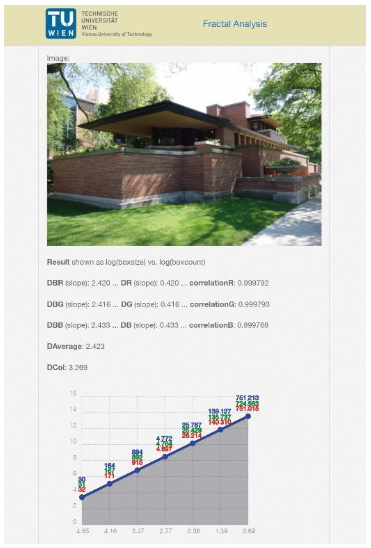
FRACAM is a web-application that analyzes pictures taken with the cell phone (Figure 2). Put in simple terms, the application extends the algorithm for vector graphics (or black and white images) by a third dimension, which is the color (or the grayscale value). The difference lies not only in the color; FRACAM also takes the surroundings into account and the perspective replaces the orthogonal projection. The vision that drove the development of the application was reaching the possibility to analyze the current status of a building as opposed to its representation as a technical drawing. While the conventional box-counting method rather analyzes the design intention contained in the latter, FRACAM is focused on the building in its real environment with adjoining buildings, surrounding vegetation as well as the sky, thus taking material properties, natural shadowing and coloring into account [5]. Since the application analyzes pictures taken with the cell phone camera, it contains color analysis methods to simultaneously examine the influence of colors on the result. While methods applied to line graphics of façades allow for a quantitative analysis, grayscale analysis rather concentrates on the texture [29,30]. In doing so FRACAM integrates, besides the basic box-counting method, the improved differential box-counting method based on square cut-outs [31] with and without shifting boxes [32], the integer ratio based box-counting method based on original image dimensions [33] with and without shifting boxes, the improved differential box-counting method for color images based on square cut-outs [34] and based on original image dimensions.
The additionally implemented methods of color analysis are important in order to determine influences caused by photography (e.g., brightness and color influenced by the date, season and possible background containing vegetation or blue sky). These methods use the average color of the image (original code see [35]), the prominent colors (see “vibrant.js” [36]), the dominant color palette (see “color-thief.js” [37]), the color count, the saturation count and the lightness count from an image according to fixed intervals.

2.4. Redundancy of Proportions, Gradient Analysis and Grid Analysis

The coordinate-based analysis of proportional redundancy is another concept to analyze and characterize complexity in architecture and can be applied in the areas of eurythmia and symmetria as described by Vitruvius (see e.g., [38]). As one of those methods, the gradient analysis explores the repetition of proportions within a 2-dimensional design such as façades. It measures the proportions as ratios or gradients and calculates the amount of repetition to identify dominant ratios [4,39]. Redundancy of proportions reduces the complexity of an objects’ appearance (see e.g., [40]) and through the use of the gradient analysis this certain redundancy is quantified. Another example of coordinate-based evaluation of proportional redundancy is the grid analysis [41]. This article is focused on the gradient analysis regarding redundancy while including certain aspects of the grid analysis into the discussion of the main thesis.
Described here in further detail, redundancy of proportion as measured with the gradient analysis method is merely a part of a holistic strategy aimed at an overall comparison of balance of the aesthetic characteristics of an object. The gradient analysis algorithm considers all possible connections of a list of given coordinates, including proportions not directly identifiable by visible lines, and measures the amount of repetitions of the gradients of all possible pairs of coordinates within a given set. This corresponds to perception based on cognitive theory and probable original artistic conscious or intuitive intention in regards to the object under scrutiny. The underlying hypothesis of the implementation of the box-counting method and this form of proportion analysis is that enhanced redundancy enhances object readability on part of the viewer (see e.g., [42]). Thus, it is argued here, that the readability of an object as a dimension, which potentially leads to a more pleasant visual perception experience if balanced properly with other layers of aesthetic complexity (for a multilayered complexity analysis within the box-counting method see [5]), may be digitally measured to an increasingly significant extent, described in multidimensional detail and therefore be made more and more tangible for conscious evaluation and design.

Implementation of the Gradient Analysis

Since the conception of gradient analysis [4] as a method to measure complexity in the area of eurythmia, the approach has undergone several refinements first described here.
Architectural Scale: All given coordinates are rounded to represent one tenth of a millimeter in the real world, which also serves to reduce calculation time.
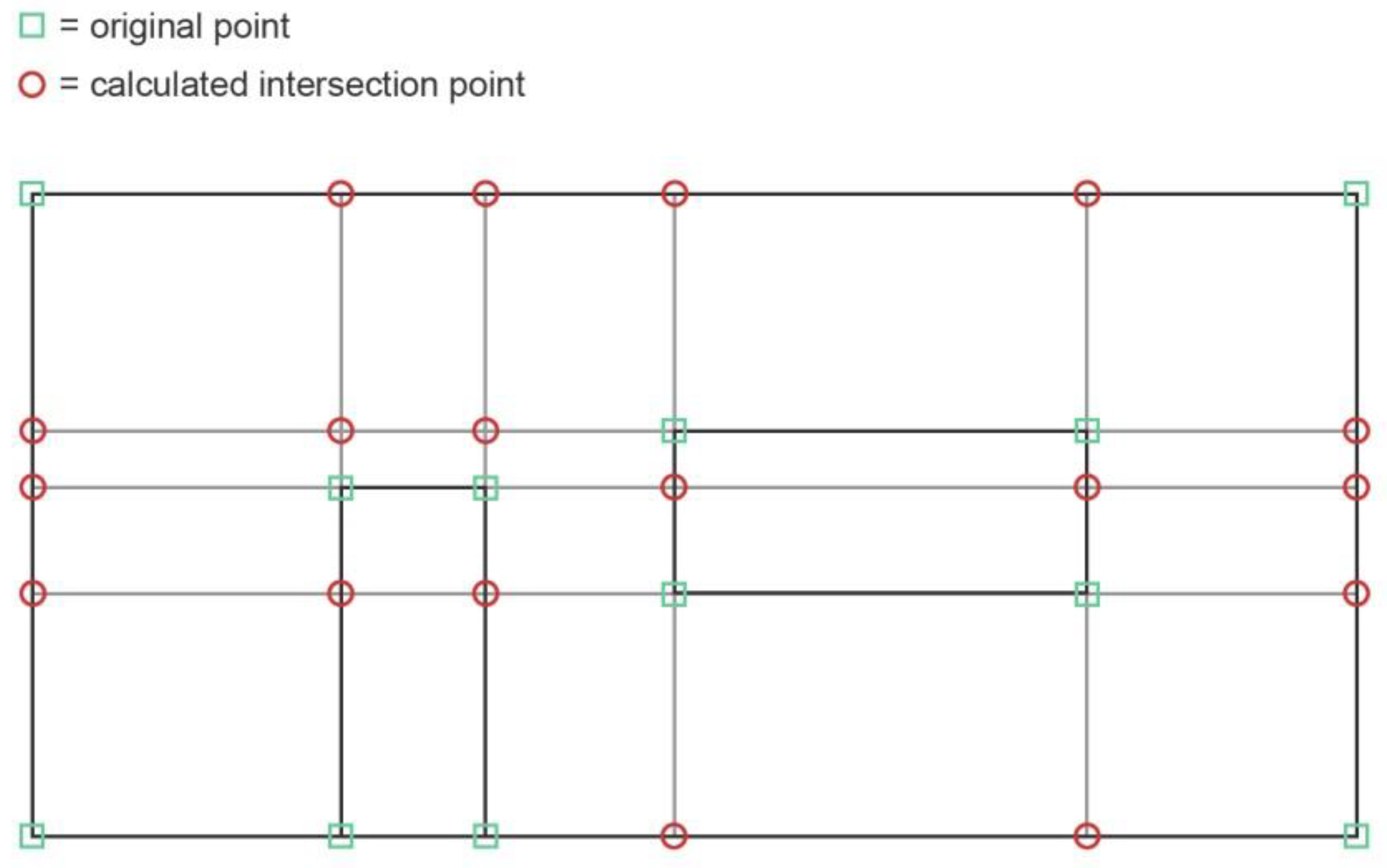
Deep gradient analysis: To take all areas e.g., of a façade of a building represented by a list of coordinates into consideration, all intersection points on an orthogonal grid which can be derived from the original coordinate list are calculated. This includes e.g., the proportion of an area between a window and the edge of a façade (see Figure 3).
Tolerance in horizontal and vertical positioning: The list of all possible intersection points is recalculated to assign the same x-value to all x-values whose difference is within a previously given range. This method is then applied also to all y-values in the same manner.
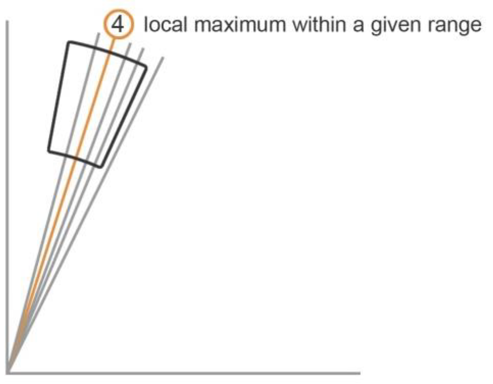
Centered Calculation of Local Maxima: Previous versions of the gradient analysis calculated local maxima in a top down fashion, starting with the 90 degree gradient and assigning all following gradients within a predefined tolerance to this gradient. The algorithm presented in this paper puts a calculation of local maxima first and assigns values within a given range to the values in a gradient list re-sorted accordingly (see Figure 4).
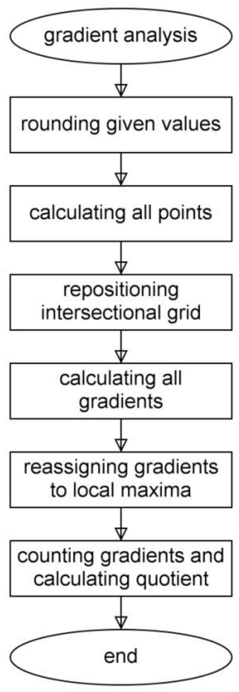
Thus, the steps of an up to date gradient analysis of a set of 2-dimensional coordinates may be described as follows (Figure 5):
  • rounding the values of a given set to represent coordinates on an architecturally relevant scale;
  • calculating all points on an orthogonal intersectional grid derived from the given set;
  • repositioning of the intersectional grid on the x- and y-axis according to a chosen vertical and horizontal tolerance value (as a percentage of maximum x- and y- distance within the given set);
  • calculating all gradients of all possible connections between points;
  • calculating local maxima of the gradients according to a chosen tolerance value;
  • assigning neighboring values within that chosen range to the gradients representing local maxima;
  • listing the remaining gradients and their weight according to the local maxima calculation;
  • counting the remaining gradients and forming the quotients of the number of remaining gradients and the possible number of connections based on the original coordinate list as well as the list of all points on the intersectional grid.
The setting of the tolerances is still undergoing a continuous refinement process. It is safe though to say, that these settings are very likely decisively linked to the complexity of the given objects measurable in different realms of aesthetic analysis, one being the box-counting dimension.

3. Results and Discussion

3.1. Box-Counting: Verification of the Data

As a first step, the authors undertake a verification process by analyzing fractals with known self-similarity dimensions and simple test cases. The next steps consist of measurements of iconic architectures and their comparison with results published in previous papers by the authors and by other scientists using slightly other algorithms; this time with the aim for an application including several methods for measuring aesthetic complexity in one system simultaneously. This means to supply architectural education and practice with yet another digital tool for the aesthetic perfection e.g., of a building façade as well as its sculpture and serves as a basis for a critique aimed at modern investor-driven buildings that argue with a modernist canon of form. It brings to light crucial differences in dealing with smoothness and modern style elements.

3.2. Box-Counting Applied to Fractal Curves

Strictly self-similar objects–in which even the smallest details are exact reductions of the whole–show a clear connection between the scaling factor s i and the number of parts N i for a certain iteration i. The value that characterizes this relation is the so-called self-similarity dimension D s . Therefore, D s serves as a reference value for other measurement methods. However, since box-counting cannot measure self-overlapping, only self-similar curves that do not overlap themselves are suitable for this reference measurement. This is due to the fact that the box-counting method measures boxes at a maximum of one time only [20]. The Koch curve, named after the mathematician Helge Koch serves as test case. First published in 1904 [43], it is one of those curves that are continuous everywhere but differentiable nowhere. With self-similar structures, such as the Koch curve, there exists a relationship between the scaling factors and the number of parts N of reduced components [20]. The power law below gives this relationship:
( 1 s ) D s = N
with D s being the self-similar dimension. Solved for D s results in:
D s = log N log ( 1 s ) = log 4 log ( 3 ) = 1.2619
The construction rule from before shows an angle of 60 degrees between the first segment and the second. However, other angles are conceivable as well. If the angle is changed, the calculation has to consider this angle in the following way:
D s = log 2 log ( 2 × cos ( α 2 ) )
which results in 1.2619 for 60 degree, 1.0986 for 40 degree and 1.6247 for 80 degree. With knowing these results, all three variants of the Koch curve with seven iterations each serve as test case for the authors’ implementation. The aim is to find the most consistent settings by changing the parameters.

3.3. Optimized Settings

In order, to clarify the optimal setting and to identify the influencing factors, the authors carried out 99 series of measurements for well-known fractal curves, including Koch curve (D = 1.26) and its variants with 40 (D = 1.1) and 80 (D = 1.62) degrees, the Minkowski curve (D = 1.50), the Sierpinski gasket (D = 1.58), the Hilbert curve (D = 2) and the Peano curve (D = 2). The calculated values served as comparison data.
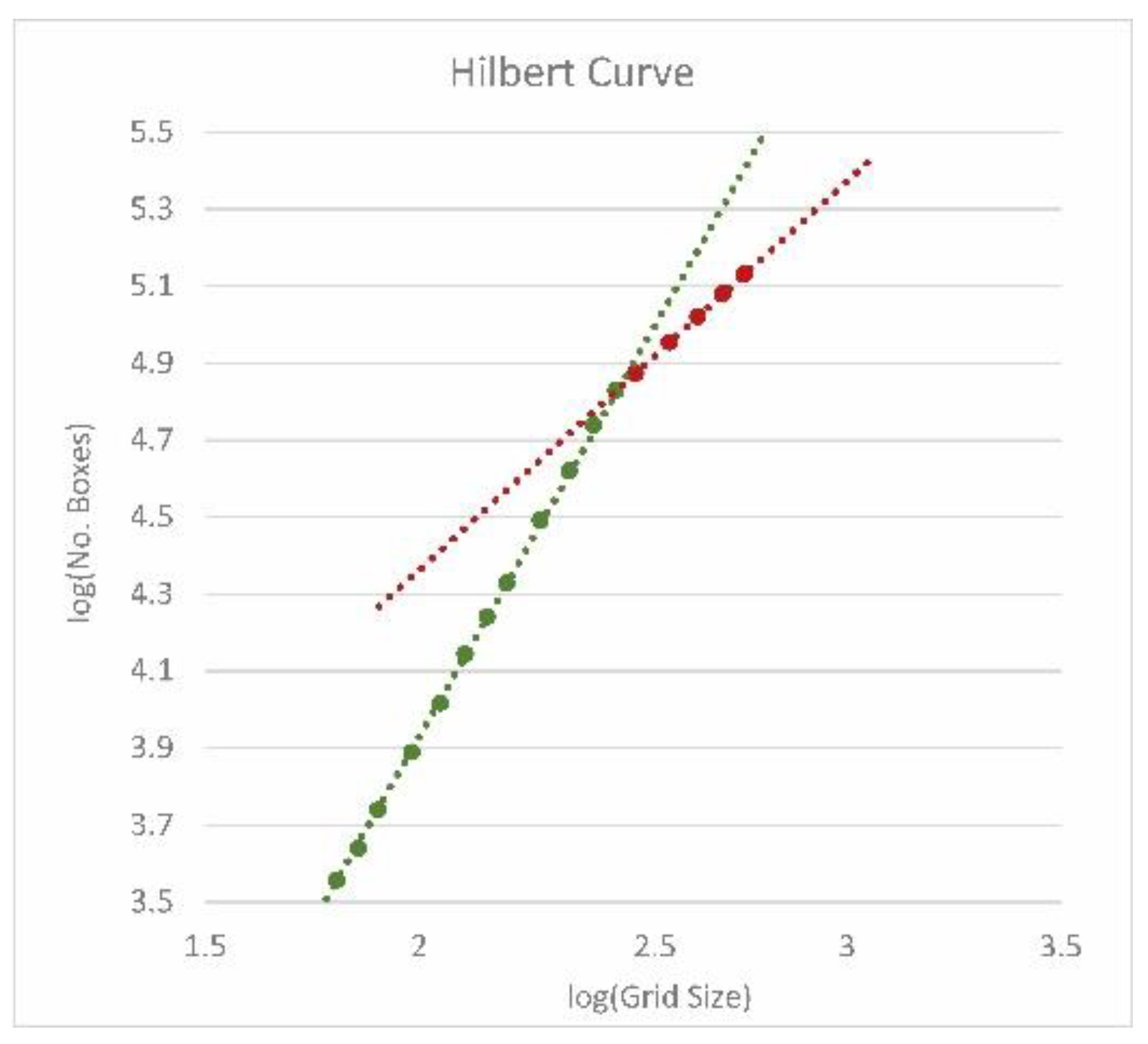
In order to obtain the standard settings for further investigations, the authors tested the influence of the number of iterations together with the enlargement factor first. In doing so, 3, 5, and 7 iterations were examined, each with an enlargement factor of 1 (means no enlargement) and in 5 steps up to 1.9. On the one hand, it became apparent that the number of iterations affects the result, with 3 iterations leading to the highest deviations and 7 iterations to the lowest. A higher number of iterations is not necessary as the results are already close to the calculated self-similar dimensions. If this parameter were to exceed a certain limit value, the data curve in the logarithmic graph would flatten and the coefficient of determination would decrease (Figure 6). On the other hand, it turned out that too much white additional space around the object under investigation worsens the result as well. This especially holds true for a medium-height dimension as for Minkowski curve. In this case, the deviation increases up to minus 13% ( D B   = 1.3).
With this knowledge, the authors tested the influences of different enlargement factors against changing intermediate steps. This confirmed the trend from before, in which the deviation increases with the degree of magnification. It was also observed that intermediate steps only partially improve the results (1 × 1, 2 × 2 and 4 × 4 steps in between were considered; Figure 7a,c: compare single columns, which include different enlargement factors). Figure 7 also shows that the influence of the enlargement factor is in any case higher than the influence of intermediate steps. This holds true for fractal curves of higher fractal dimension (Hilbert Curve with a fractal dimension of 2.0) and those with a lower dimension (Koch Curve with a fractal dimension of 1.26). The next step was an analysis with the same settings, but with 3 × 3 additional offsets (Figure 7b,d). This led to slightly better results, especially for curves with a fractal dimension above 1.5–it had a greater effect on the higher enlargement factors, which otherwise led to larger deviations (compare corresponding columns of different enlargement factors in Figure 7a,b).
The test series was then continued with magnification factors of 1.1, 1.2 and 1.3 with different iterations (5, 6, 7), offsets (without or 10 × 10) and intermediate steps (0, 6 and 10). The results were consistently promising with a deviation of less than 5% (with the exception of complex curves with fractal dimensions of 2). An increase in the number of start boxes for the shortest side from 3 to 5 led to a further improvement, especially for curves with either smaller or larger fractal dimensions. However, with the Hilbert curve, it turned out that the data curves flatten out at the end, indicating that the smallest box sizes do not cover any new turns of the curve. That means the scale of the grid size no longer corresponds to the scale of the smallest details of the curve. Hence, with a higher number of initial boxes of the smallest side, the number of iterations must be reduced for this curve. This particularly shows the influence of the number of initial boxes and of the number of iterations (or in other words the influence of the choice of the largest and smallest box size). In general, it can be deduced that a size of four boxes for the smallest side is a good choice in most cases. This corresponds with the findings of Fourtan-Pour et al. [26].
The pre-defined settings, including variations for the enlargement factors of 1.1, 1.15 and 1.2%, show a clear trend. While fractals with a small fractal dimension close to D s   = 1 (self-similar dimension) almost reach or only slightly exceed the calculated value, fractals with a high fractal dimension deviate more clearly from the expected value. In addition, the latter fall below the value in any case. It also shows that these observations hold true for both the median and the calculated average value (Figure 8a). The measured value ( D B ), which considers the smallest possible number of covered boxes, shows a similarly high positive deviation (by +3%) for fractals with low self-similar dimensions, as show a negative deviation (by −3%) for fractals with high values (Figure 8b). In any case, the enlargement factors of 1.1% gives the most accurate results for all fractals in the test series. Since analyzes of façades only rarely exceed the value of 1.7 or fall below 1.3, the following measurements will use an enlargement factor of 1.15%, and above all the median is considered. This also corresponds more precisely with the statistical analysis of accuracy as shown by the quartiles.
Finally, the values that led to the best results for all curves, considering an acceptable performance, were:
  • Enlargement factor: 1.15
  • Number of boxes for the shortest side: 4 (here the authors made a compromise between the two test series of 3 and 5 starting boxes; during the verification phase it turned out that the former worked well for less complex curves, while the latter gave better results for more complex curves)
  • Offsets: 5 × 5 (the authors reduced this number due to performance reasons)
  • Steps in between: 5 (this value divides the box size in the x-direction between the largest and the next smaller one, whereby the latter is not allowed to be undercut; hence, it defines a maximum value that can change depending on the proportion of the bounding box; e.g., for a square shape and 4 starting boxes for the smallest side, the next smaller grid size equals 8; accordingly, there are only 3 intermediate steps possible; such an adjustment is automatically done by the program)
The final settings with 1.15% enlargement factor lead to the following results–with D M e d i a n , D s and the corresponding deviation [%] given in brackets:
  • Koch curve ( D M e d i a n   = 1.2639, D s   = 1.2619, 0.16%)
  • Koch curve with 40° ( D M e d i a n   = 1.0963, D s   = 1.0986, −0.21%)
  • Koch curve with 80° ( D M e d i a n   = 1.6041, D s   = 1.6247, −1.27%)
  • Minkowski curve ( D M e d i a n   = 1.4782, D s   = 1.50, −1.45%)
  • Sierpinski gasket ( D M e d i a n   = 1.5745, D s   = 1.5850, −0.66%)
  • Hilbert curve ( D M e d i a n   = 1.9256, D s   = 2.0, −3.72%)
  • Peano curve ( D M e d i a n   = 1.9238, D s   = 2.0, −3.81%)

3.4. Box-Counting Applied to Test Cases

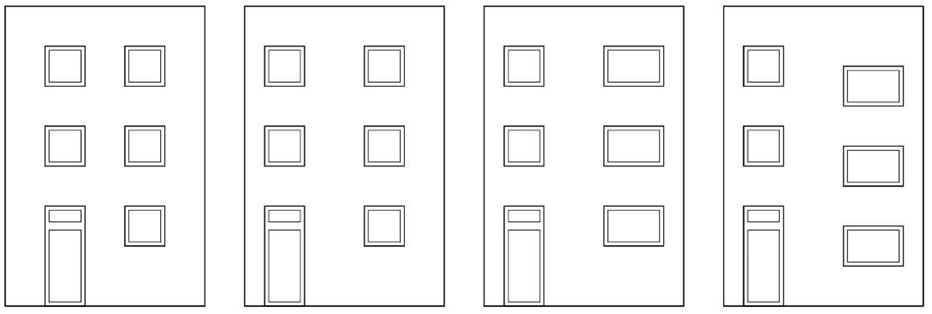
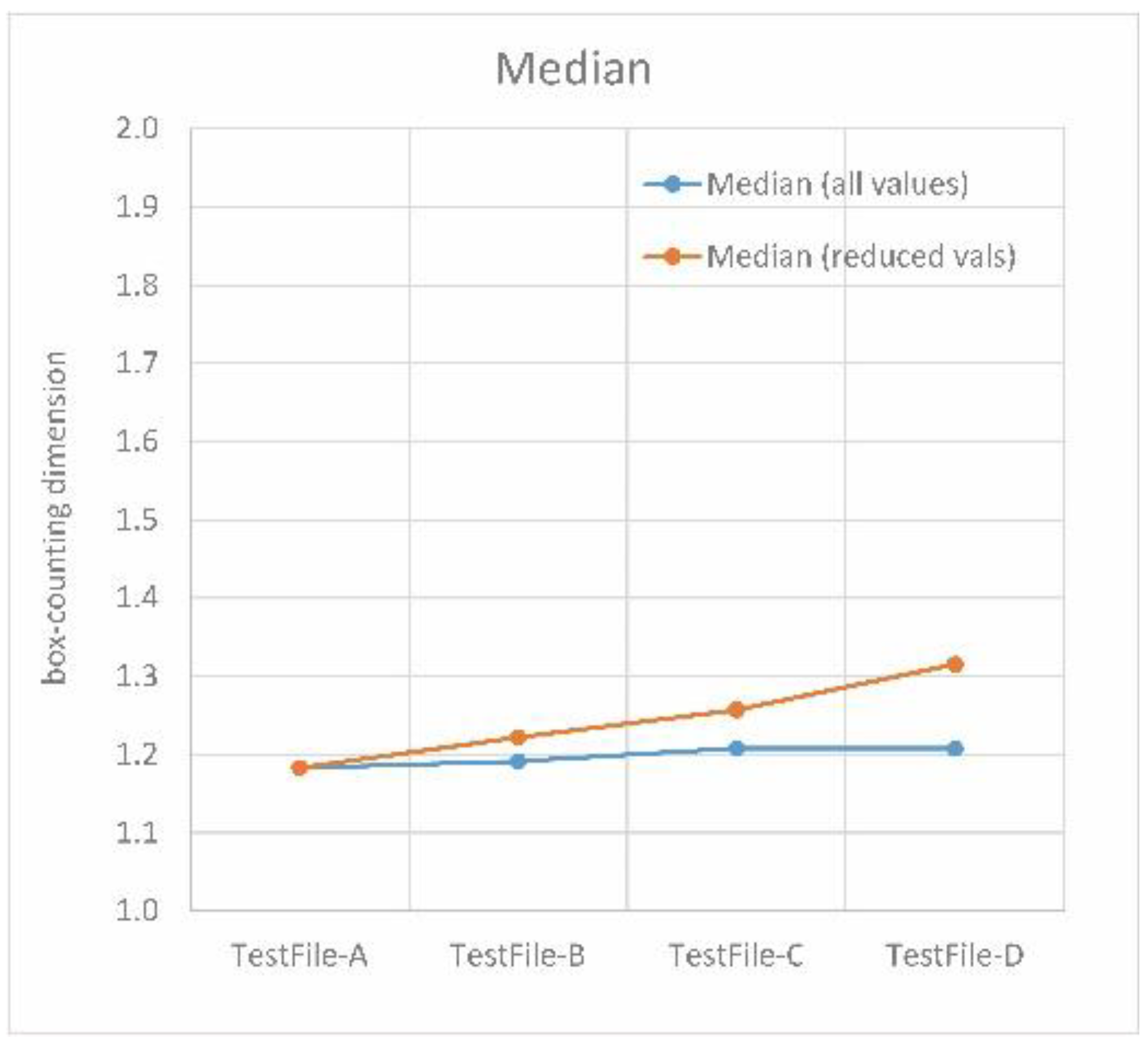
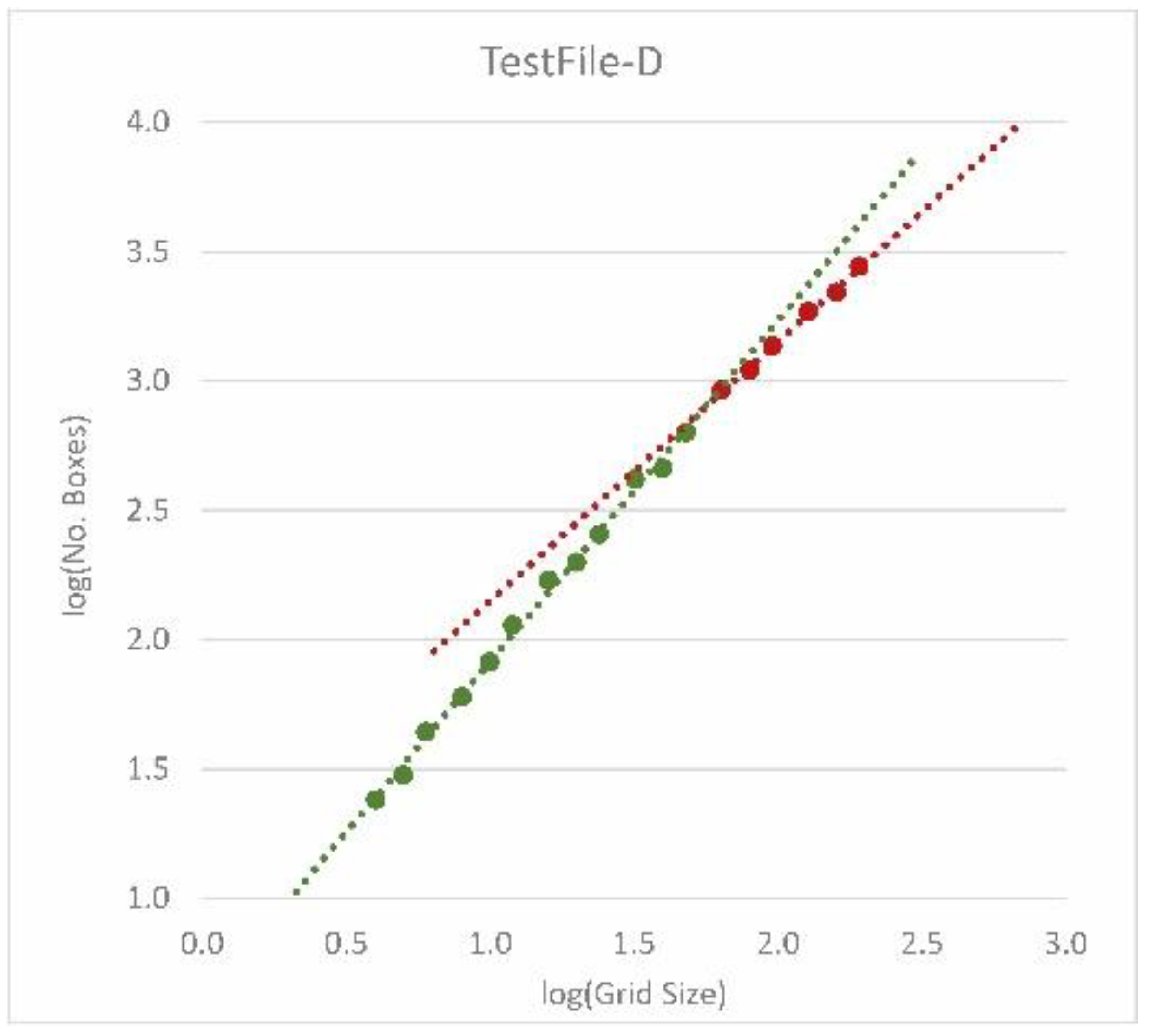
Some simple designs (Figure 9) already published at eCAADe 2015 again serve as test cases [4], this time not only for proportion measurement but also for the box-counting method. Since these are simple geometries without ornamentation, the resulting box-counting dimensions remain comparatively low. The first four designs (Figure 9) do not differ in the number of openings, but in their proportions and spacing. As shown in Figure 10, the results are very similar to each other; especially when all values are considered (“all values”). “All values” simply states that all results from all iterations are taken into account. However, the part of the data curve with the smallest deviation counts, i.e., the range that offers the straightest part of the data curve (Figure 11). This range is characterized by a coefficient of determination close to one. With the examples presented here, the box-counting dimension slightly increases from the first to the fourth example. This illustrates the importance of defining the data range with the greatest correlation between the grid size and the number of boxes covered. This example shows a correlating increase in the box-counting dimension with the complexity of the design.

3.5. Box-Counting Applied to Iconic Architecture

3.5.1. Settings

The search for the straightest possible section of the data curve also holds true for façades. This time, however, the smallest and the largest box sizes also depends on the building size [8]. First, the lowest limit for the smallest box size depends on the smallest details shown on the plan. This corresponds with the area of sharp vision and the theoretical distance to the object. Second, the field of vision and fictitious distances to the object define the range of box sizes (smallest and largest). “Fictitious” because it is a measurement of the architect’s design intention and not what is actually built. In the latter case, one would only seldom approach a building in a direction perpendicular to the façade but in line with the street, in most cases parallel to the building’s front. In [8] a calculation of box sizes depending on the field of vision and the area of sharp vision was presented, which so far has proven to be suitable. There is a relationship between height and viewing angle through:
Distance = (Building height)/tan (Angle)
As a result of Maertens [44] und Bovill [23] the authors first defined the angles of 18°, 27° and 45° in order to calculate the fictitious distances from the building height: 18° corresponds to an overview with the surroundings, 27° to an overview and 45° to the representation of individual parts. Finally, the calculated distances together with the angles 1°, 7°26’ and 10° give an indication of the range of the boxes. For the smallest line differences, on the other hand, an angle of 10 min applies in dependence on the distances [8]. Table 1 shows the calculation for the north elevation of the House Steiner. In the range of box sizes, the straightest section of the data curve is again of interest. Basically three results are possible:
(1)
All data points are very close to the regression line, i.e., there is a clear relationship between box size and number of covered boxes over the entire range under consideration.
(2)
There are two clearly separable intersecting straight segments, with different gradients. Accordingly, a range with larger boxes can lead to higher fractal dimensions, followed by a section with a smaller fractal dimension.
(3)
The data points show a continuous curve without straight segments.
While the first two cases occurred in the buildings examined so far, the third case has not yet been observed. The kink in the data curve i.e., the point of intersection of the two line-segments in case 2, observed mainly in modern buildings, corresponds to the change in focus from main design on a large scale to the small scale, where the details are missing. The latter section therefore offers a lower fractal dimension. This also corresponds to the idea of classical modernism to deliberately avoid ornamentation.
An applicatory novelty of the method presented in this paper is, that a script is available that can be used directly in a CAD program (Rhinoceros®). Furthermore, the use of Grasshopper® for an architectural environment is “state of the art” considering the practical introduction of such analyses into the design process.

3.5.2. Measurements

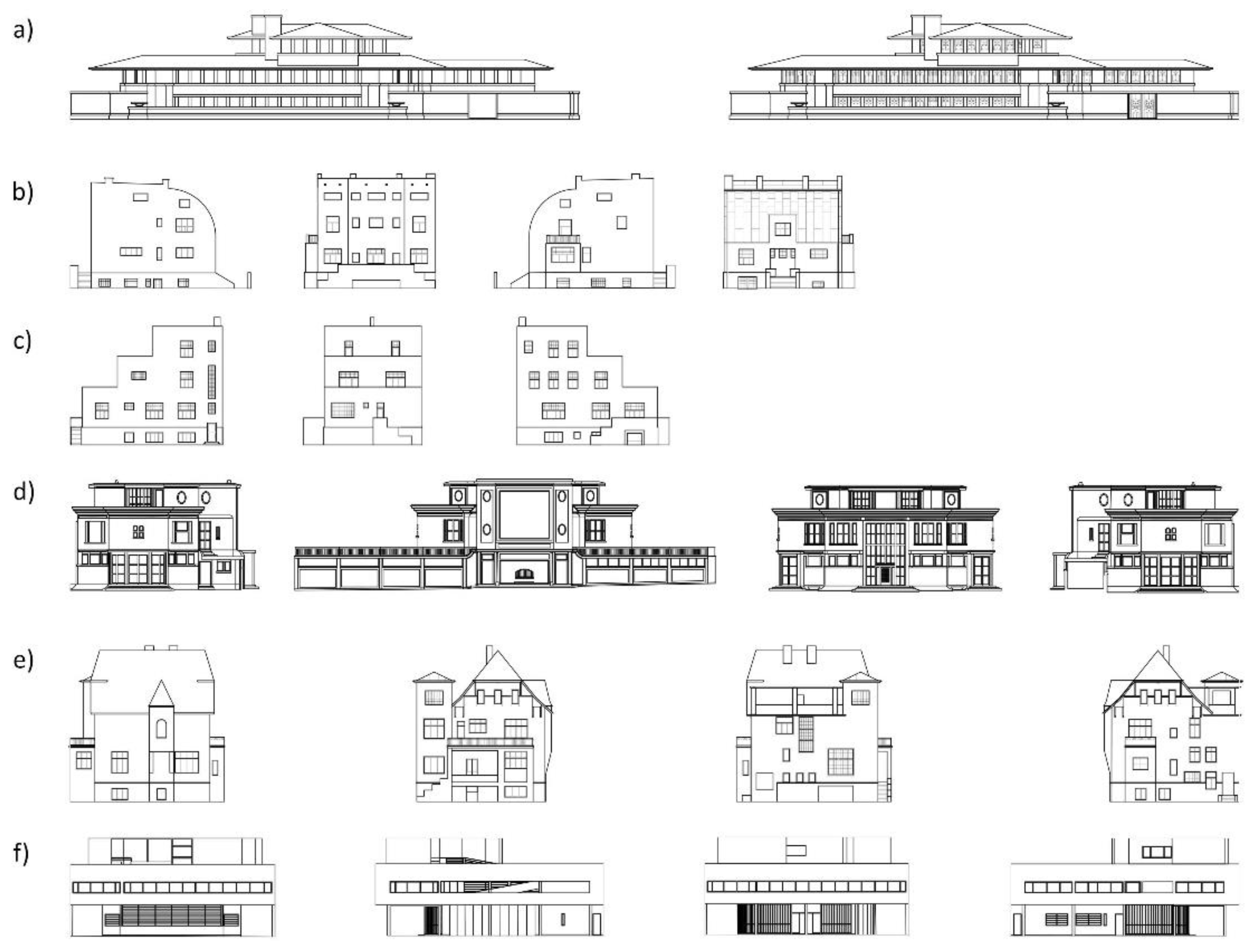
Examples of iconic architecture analyzed in this paper include Robie House by Frank Lloyd Wright, Villa Savoye and Villa Schwob by Le Corbusier, House Mandl, House Scheu and House Steiner by Adolf Loos (Figure 12). This is due to the fact that reference data exist since various scientists have already measured them using box-counting [3,8,45,46].
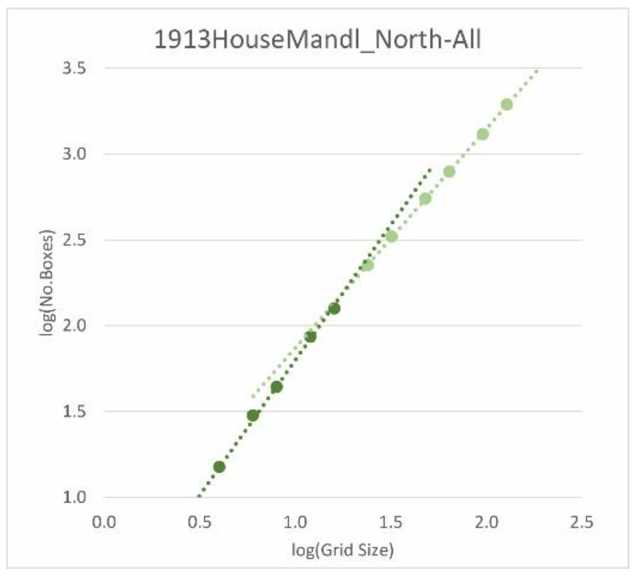
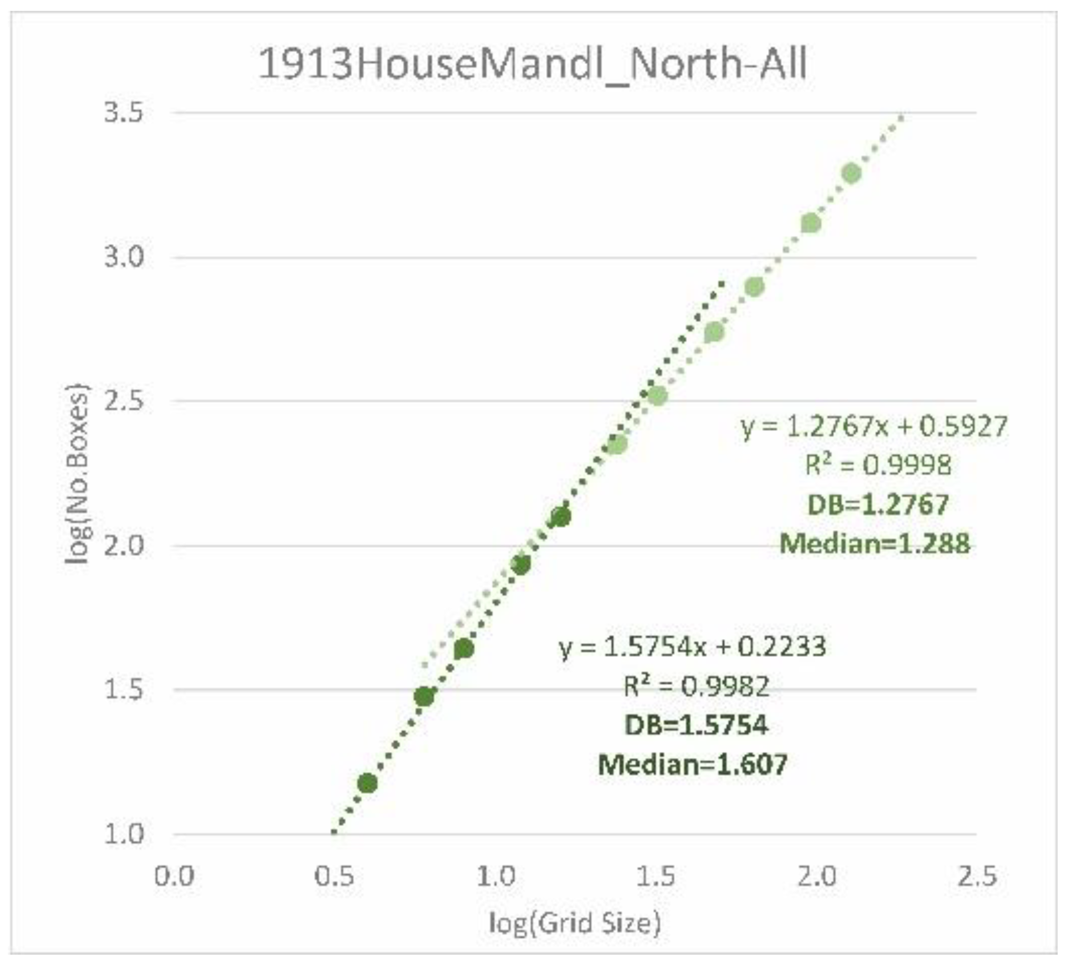
The comparison with previous measurements shows similarities, but also deviations. It is therefore important to understand the influence of settings, but also to specify the range of box sizes and the D B as a box plot. While the range defines the validity of the measurement result, the latter provides information about the spread and thus the accuracy. In this paper, a more accurate measurement method with the calibration of the parameters based on several well-known fractals was presented (see Section 3.3 “Optimized Settings”). In addition to the calibration using known fractal dimensions, the definition of the range of the straight section of the data curve is of great importance (i.e., the range of significant correlation between the grid size and the number of covered boxes). Within the range of box sizes, depending on the building height and distance, it is possible that there is more than one straight section (see Figure 13).
As mentioned before, for interpretation of the results, a box plot of all D B is an indication for the accuracy and the scattering respectively of all box-counting dimensions of a series of measurements. Figure 14 shows the results, with the range under consideration divided into two different straight-line sections (referred to as “first” and “sec”). As can be seen, the median of the first section (the range of larger box sizes) is always higher than the second one. This corresponds to the endeavors of classical modernism to consciously dispense with ornamentation on a smaller scale.
As Figure 14 indicates, there are clearly different variations in the series of measurements. The percentage at the bottom of the chart gives another indication of the variation; it is the sum of the two middle quartiles (the interquartile range) in relation to the maximum dimensional value of two. A very high variance (percentage) indicates a less meaningful result. This applies, for example, to the north facade (both sections) of the Villa Savoye. In comparison, all second sections of House Mandl and House Steiner show less variation. In these cases, moreover, the box-counting dimensions are similarly high and by that indicate a similar roughness in this range. If, on the other hand, one looks at the first sections of the House Steiner, there are similarities between the north and south façades or the east and west façades, with the former showing a lower median than the latter.
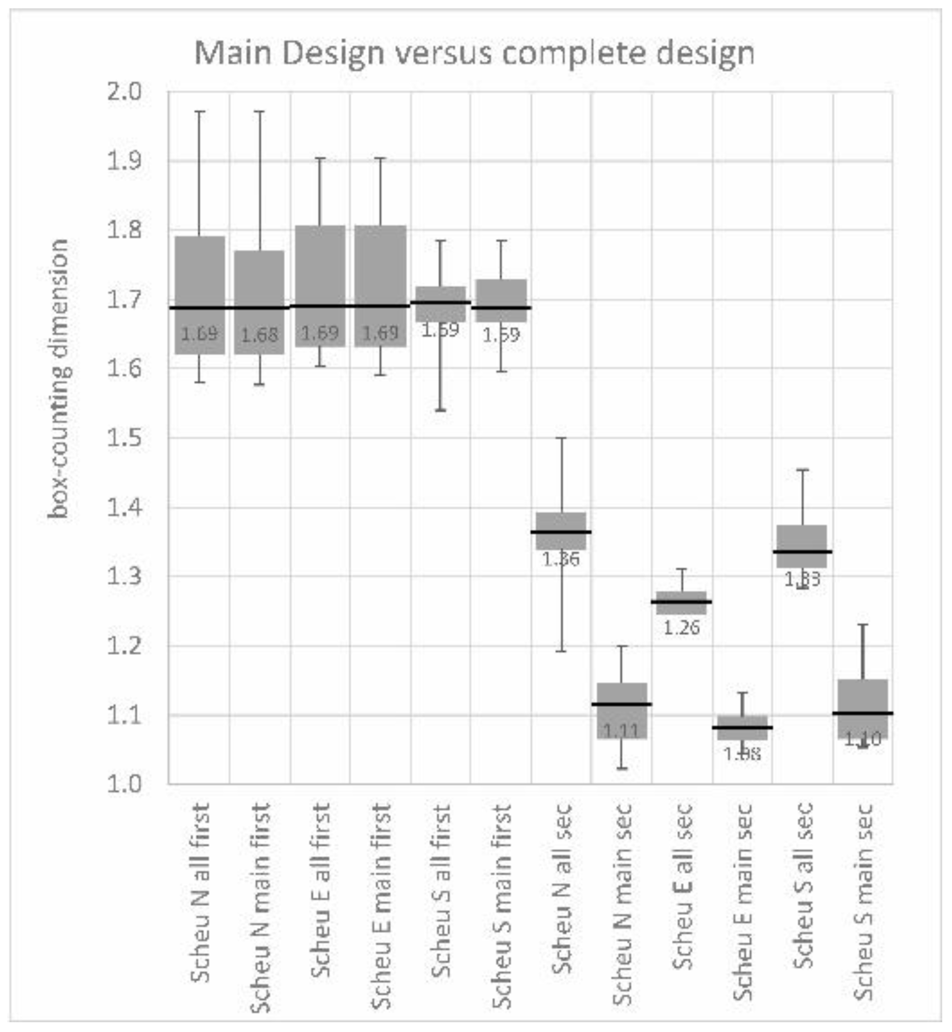
Regarding House Mandl, House Scheu, and House Steiner, two different measurement series were made: on the one hand, including only the main design elements (attached abbreviation “main”) and on the other hand including the design with window frames and other secondary elements (attached abbreviation “all”). Figure 15 shows the result for House Steiner. It can be clearly stated that for the first section there is hardly any difference between the results for the entire design and the main elements. Only in the second section are the values for the main design significantly lower than when including secondary elements. This can be seen as a further indication of the main design focus. On the other hand, it shows that there are nonetheless additional elements in the small scale, even if there is no ornament.
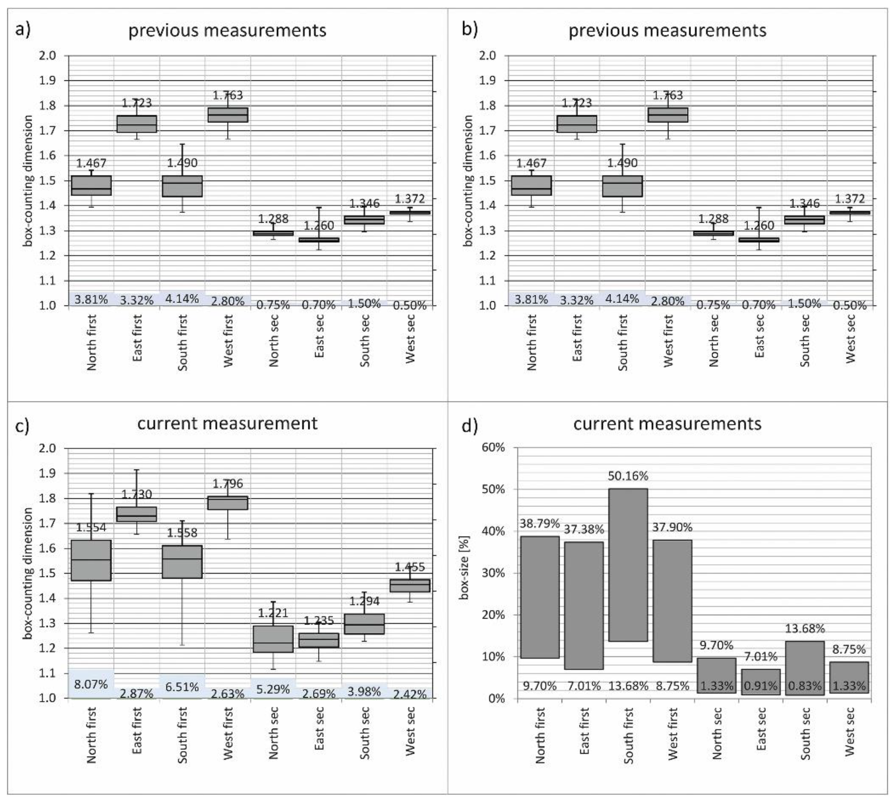
Figure 16 shows a comparison of previous measurements for House Mandl (Lorenz 2014) with those under usage of the program presented here. As can be seen from the figure, all results provide similar values for the same range of box sizes (see Figure 16 right; box size given as a percentage of the height), both in the median and in the box plot (see Figure 16 left).
The box-counting implementation presented here also takes the smallest number of covered boxes for each grid size for the first time into account. This means that for each grid size and its varying positions (due to displacement) the smallest number of covered boxes is noted for a separate calculation. First results show a good approximation regarding the medians (Figure 17). In future work, this will be an additional parameter that should be taken into account.
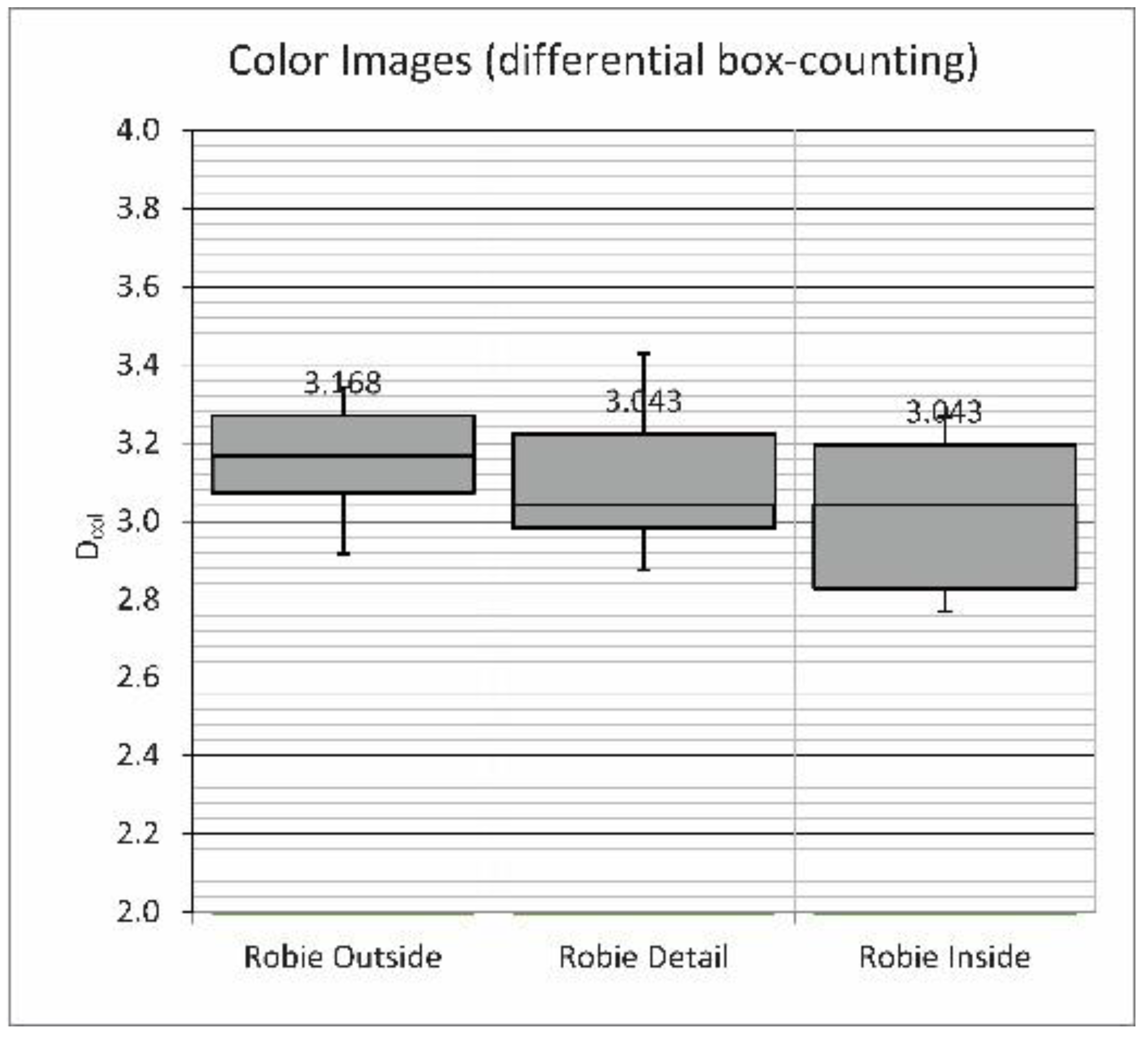
The measurement with the differential box-counting method (the measurement of color images with FRACAM) leads to fractal dimensions approximating the value three. The interpretation of the measurement is carried out in accordance with the 2D calculation in a box plot diagram. This time the analysis includes several camera positions around the building (or inside) that provide different values, but within close range (Figure 18). Even if no connection between color and fractal dimension could be established so far [5], the influence of different weather conditions should be examined, which is a task for future work. In the meantime, it is recommended that only pictures taken on the same date and time be included in a calculation. Figure 18 shows such a result for Robie House.

3.6. Gradient Analysis Applied to Test Cases

The test cases A–D show, as expected and as was the case in earlier observations using previous gradient analysis algorithms, quotients tending in the direction of 1 as complexity of the object under scrutiny increases in the realm of the aspect of proportion labeled eurythmia by Vitruvius [4]. The newly introduced intersectional grid, including the x- and y-tolerance, however, has revealed that the reduction of complexity in horizontal and vertical alignment does not necessarily lead to lower values of the overall quotients in linear tendency. The reduction of complexity of a part of the system thus does not guarantee the reduction of complexity of the whole system.

3.7. Gradient Analysis Applied to Iconic Architecture

In comparison to the test cases the increase of the number of coordinates in given sets of iconic architecture shows, that there is a significant decrease of the value of the resulting quotients. This appears to signify more than a decrease in proportional redundancy, it hints at the fact an increase of x- and y-values results in an increasingly dense intersectional grid, which makes the repetition of gradients, in general, more likely. To sensibly compare complexity on the layer of proportional redundancy this comparison must therefore be local, i.e., confined to objects with a similar amount of coordinates.

4. Conclusions

The authors showed that fractal geometry based analysis in several methodic layers enables a detailed qualitative description of visual characteristics. This is e.g., implied by the range of coherent characteristics, expressed by statistical values when using the box-counting method. Box-counting thus remains an important quantitative method for describing complexity in architecture with optimization potential, especially to be reckoned with in future systems that will integrate several strategies to balance aesthetic complexity. The consistency of the architectural elements from the whole to the smallest perceptible detail in the analyses presented here leading to a trend of data points in a double logarithmic diagram is yet another proof for the relevance of box-counting in this matter.
The above-mentioned color analysis methods, which form the basis for the mobile phone application FRACAM, are particularly aimed at measuring correlations with results of the extended measurement methods for color photos. In [5] several series of measurements were carried out, including the Robie House, whereby no correlation could be found between the fractal dimension and the mean color value, the predefined color areas, the saturation or the brightness. From this, it can be inferred that apparently the color of an image does not influence the result to an extent as significant as the shapes of the objects under scrutiny, i.e., the building and its surroundings.
The gradient analysis as a coordinate-based method has shown that differences in complexity may be also a local matter, allowing for a comparison of designs with a certain number of defining coordinates. Therefore, roughness-evaluation is bound to play an important role for the optimization for coordinate based proportion analysis.
Although the described methods and algorithms may be integrated into so-called AI-systems, complexity evaluation as a whole will remain solely a macro-layer within an overall design or design evaluation process. Even if certain complexity measures can be identified as clues and even a necessity for good or even responsible design, they are not likely to be sufficient without for excellent design work without other layers of reflection beyond the grasp of mere digital algorithmic evaluation. Nonetheless will the digital algorithms presented in this article further the quality of architectural design and critique in an age of rising task complexity and global responsibility.

Author Contributions

Conceptualization, W.E.L. and M.K.; methodology, W.E.L. and M.K.; software “box-counting”, W.E.L.; software “gradient analysis”, M.K.; validation, W.E.L. and M.K.; formal analysis, W.E.L. and M.K.; investigation, W.E.L. and M.K.; resources, W.E.L. and M.K.; data curation, W.E.L. and M.K.; writing—original draft preparation, W.E.L. and M.K.; writing—review and editing, W.E.L. and M.K.; visualization, W.E.L. and M.K. All authors have read and agreed to the published version of the manuscript.

Funding

This research received no external funding (Open Access Funding by TU Wien).

Data Availability Statement

The data presented in this study is available at: http://www.iemar.tuwien.ac.at/processviz/MultilayeredComplexityAnalysis-2021/MultilayeredComplexityAnalysis.html (accessed on 28 November 2021).

Conflicts of Interest

The authors declare no conflict of interest.

References

  1. Mandelbrot, B.B. Die Fraktale Geometrie der Natur; Birkhäuser Verlag: Berlin, Germany, 1991. [Google Scholar]
  2. Mandelbrot, B.B. Les Objets Fractals: Forme, Hazard et Dimension, 2nd ed.; Flammarion: Paris, France, 1984. [Google Scholar]
  3. Bovill, C. Fractal Geometry in Architecture and Design; Birkhäuser: Boston, FL, USA, 1996. [Google Scholar]
  4. Kulcke, M.; Lorenz, W.E. Gradient-Analysis: Method and Software to Compare Different Degrees of Complexity in the Design of Architecture and Design objects. In Real Time, Proceedings of the 33rd International Conference on Education and Research in Computer Aided Architectural Design in Europe, Vol. 1, TU Wien, Vienna, Austria, 16–18 September 2015; Martens, B., Wurzer, G., Grasl, T., Lorenz, W.E., Schaffranek, R., Eds.; Vienna University of Technology: Vienna, Austria, 2015; pp. 415–424. [Google Scholar]
  5. Lorenz, W.E.; Wurzer, G. FRACAM: A 2.5D Fractal Analysis Method for Facades Test Environment for a Cell Phone Application to Measure Box Counting Dimension. In Anthropologic—Architecture and Fabrication in the Cognitive Age, Proceedings of the 38th International Conference on Education and Research in Computer Aided Architectural Design in Europe, Vol. 1, TU Berlin, Berlin, Germany, 16–18 September 2020; Werner, L.C., Koering, D., Eds.; TU Berlin: Berlin, Germany, 2020; pp. 495–504. [Google Scholar]
  6. Franck, G.; Franck, D. Architektonische Qualität; Hanser: München, Germany, 2008. [Google Scholar]
  7. Salingaros, N.A. A Theory of Architecture; Umbau Verlag: Solingen, Germany, 2006. [Google Scholar]
  8. Lorenz, W.E. Fraktalähnliche Architektur—Einteilung und Messbarkeit: Ein Programm in VBA für AutoCAD. Ph.D. Thesis, TU Wien, Vienna, Austria, 2013. [Google Scholar]
  9. Mandelbrot, B.B. Scalebound or scaling shapes: A useful distinction in the visual arts and in the natural sciences. Leonardo 1981, 14, 45–47. [Google Scholar] [CrossRef]
  10. Peitgen, H.-O.; Saupe, D. The Science of Fractal Images; Springer: New York, NY, USA, 1988. [Google Scholar]
  11. Evers, B. Architekturtheorie: Von der Renaissance bis zur Gegenwart; Taschen Verlag: Köln, Germany, 2006. [Google Scholar]
  12. Hoffmann, D. Frank Lloyd Wright’s Robie House; Dover Publications, Inc.: Mineola, NY, USA, 1984. [Google Scholar]
  13. Neumeyer, F. Quellentexte zur Architekturtheorie. Bauen beim Wort Genommen; Prestel: München, Germany, 2002. [Google Scholar]
  14. Sullivan, L.H. The tall office building artistically considered. Lippincott’s Magazine, 23 March 1896; 403–409. [Google Scholar]
  15. Kruft, H.-W. Geschichte der Architekturtheorie. Studienausgabe: Von der Antike bis zur Gegenwart; C.H.Beck: München, Germany, 1995. [Google Scholar]
  16. Le Corbusier. Vers Une Architecture; G. Crès et Cie: Paris, France, 1922. [Google Scholar]
  17. Lorenz, W.E. Fractals and Fractal Architecture. Master’s Thesis, TU Wien, Vienna, Austria, 2003. [Google Scholar]
  18. Mandelbrot, B.B. How long is the coast of Britain? Statistical self-similarity and fractional dimension. Science 1967, 156, 636–638. [Google Scholar] [CrossRef] [PubMed] [Green Version]
  19. Husain, A.; Reddy, J.; Bisht, D.; Sajid, M. Fractal Dimension of Coastline of Australia. Sci. Rep. 2021, 11, 6304. [Google Scholar] [CrossRef] [PubMed]
  20. Peitgen, H.-O.; Jürgens, H.; Saupe, D. Chaos and Fractals—New Frontiers of Science; Springer: New York, NY, USA, 1992. [Google Scholar]
  21. Hausdorff, F. Dimension und äußeres Maß. Math. Ann. 1919, 79, 157–179. [Google Scholar] [CrossRef]
  22. Ostwald, M.J.; Vaughan, J. The Fractal Dimension of Architecture; Birkhäuser: Basel, Switzerland, 2016. [Google Scholar]
  23. Bovill, C. Fractal Calculations in Vernacular Design. In IASTE Working Paper Series Vol. 97 Critical Methodologies in the Study of Traditional Environments, Proceedings of the International Association for the Study of Traditional Environments (IASTE Conference 14th–17th December 1996, Berkeley); University of California at Berkeley, Centre for Environmental Design: Berkeley, CA, USA, 1997; pp. 35–51. [Google Scholar]
  24. Vaughan, J.; Ostwald, M.J. Refining the Computational method for the Elevation of Visual Complexity in Architectural Images: Significant Lines in the Early Architecture of Le Corbusier. In The New Realm of Architectural Design, Proceedings of the 27th International Conference on Education and Research in Computer Aided Architectural Design in Europe, Istanbul, Turkey, 6–19 September 2009; Çagdas, G., Colakoglu, B., Eds.; İstanbul Teknik Üniversitesi: Istanbul, Turkey, 2009; pp. 689–696. [Google Scholar]
  25. Corbit, J.D.; Garbary, D.J. Fractal dimension as a quantitative measure of complexity in plant development. Proc. R. Soc. Lond. Ser. B Biol. Sci. 1995, 262, 1–6. [Google Scholar] [CrossRef]
  26. Fourtan-Pour, K.; Dutilleul, P.; Smith, D.L. Advances in the implementation of the box-counting method of fractal dimension estimation. Appl. Math. Comput. 1999, 105, 195–210. [Google Scholar] [CrossRef]
  27. Taylor, R.P. Architect reaches for the clouds. Nature 2001, 410, 18. [Google Scholar] [CrossRef] [PubMed]
  28. Robert McNeel and Associates. Rhinoceros 3D, Version 6.0; Robert McNeel and Associates: Seattle, WA, USA, 2010. [Google Scholar]
  29. Wurzer, G.; Lorenz, W.E. FRACAM—Cell Phone Application to Measure Box Counting Dimension. In Protocols, Flows, and Glitches, Proceedings of the 22nd Computer-Aided Architectural Design Research in Asia Conference, Xi’an Jiaotong-Liverpool University, Suzhou, China, 5–8 April 2017; Janssen, P., Loh, P., Raonic, A., Schnabel, M.A., Eds.; Xi’an Jiaotong-Liverpool University: Suzhou, China, 2017; pp. 725–734. [Google Scholar]
  30. Backes, A.; Bruno, O.M. A New Approach to Estimate Fractal Dimension of Texture Images. In Image and Signal Processing, Proceedings of the 3rd International Conference, ICISP, Cherbourg-Octeville, France, 1–3 July 2008; Elmoataz, A., Lezoray, O., Nouboud, F., Mammass, D., Eds.; Springer: Berlin/Heidelberg, Germany, 2008; pp. 136–143. [Google Scholar] [CrossRef] [Green Version]
  31. Sarker, N.; Chaudhuri, B.B. An efficient differential box-counting approach to compute fractal dimension of image. IEEE Trans.Syst. Man Cybern. 1994, 24, 115–120. [Google Scholar] [CrossRef] [Green Version]
  32. Liu, Y.; Chen, L.; Wang, H.; Jiang, L.; Zhang, Y.; Zhao, J.; Wang, D.; Zhao, Y.; Song, Y. An improved differential box-counting method to estimate fractal dimensions of gray-level images. J. Vis. Commun. Image Represent. 2014, 25, 1102–1111. [Google Scholar] [CrossRef]
  33. Long, M.; Peng, F. A Box-Counting Method with Adaptable Box Height for Measuring the Fractal Feature of Images. Radioengineering 2013, 22, 208–213. [Google Scholar]
  34. Nayak, S.R.; Mishra, J. On Calculation of Fractal Dimension of Color Images. Int. J. Image Graph. Signal Process. 2017, 9, 33–40. [Google Scholar] [CrossRef] [Green Version]
  35. GitHub: GetAverageColourAsRGB.js. Available online: Gist.github.com/nucliweb/a3a23febee3ccb9a1b5dc93dadf94fe7 (accessed on 14 April 2020).
  36. GitHub: Vibrant.js by Zwarts, J. Available online: https://github.com/jariz/vibrant.js/ (accessed on 14 April 2020).
  37. Color Thief by Dhakar, L. Available online: https://lokeshdhakar.com/projects/color-thief/ (accessed on 14 April 2020). Color Thief is licensed under the MIT License https://github.com/lokesh/color-thief/blob/master/LICENSE.
  38. Rowland, I.D.; Howe, T.N. Vitruvius—Ten Books on Architecture; Cambridge University Press: Cambridge, UK, 1999. [Google Scholar]
  39. Kulcke, M.; Lorenz, W.E. Utilizing Gradient Analysis within Interactive Genetic Algorithms. In Complexity & Simplicity, Proceedings of the 34th International Conference on Education and Research in Computer Aided Architectural Design in Europe, Vol. 2, University of Oulu, Oulu, Finland, 22–26 August 2016; Herneoja, A., Österlund, T., Markkanen, P., Eds.; University of Oulu: Oulu, Finland, 2016; pp. 359–364. [Google Scholar]
  40. Cube, F. Kybernetische Grundlagen des Lernens und Lehrens; Ernst Klett Verlag: Stuttgart, Germany, 1965. [Google Scholar]
  41. Kulcke, M. Gestaltkonfiguration und Verantwortung. Ph.D. Thesis, HafenCity University, Hamburg, Germany, 2019. [Google Scholar]
  42. Guski, R. Wahrnehmen—Ein Lehrbuch; Kohlhammer: Stuttgart, Germany, 1996. [Google Scholar]
  43. Koch, H. Sur une courbe continue sans tangente, obtenue par une construction géométrique élémentaire. Ark. Mat. Astron. Fys. 1904, 1, 681–702. [Google Scholar]
  44. Maertens, H. Der Optische Maßstab: Oder die Theorie und Praxis des Asthetischen Sehens in der Bildenden Kunst; Wasmuth: Berlin, Germany, 1884. [Google Scholar]
  45. Ostwald, M.J.; Vaughan, J.; Tucker, C. Characteristic Visual Complexity: Fractal Dimensions in the Architecture of Frank Lloyd Wright and Le Corbusier. Nexus Archit. Math. 2008, 7, 217–232. [Google Scholar] [CrossRef]
  46. Lorenz, W.E. Measurability of Loos’ rejection of the ornament: Using box-counting as a method for analyzing facades. In Fusion, Proceedings of the 32nd International Conference on Education and Research in Computer Aided Architectural Design in Europe, Vol. 1, Northumbria University, Newcastle upon Tyne, UK, 10–12 September 2014; Thompson, E.M., Ed.; Northumbria University: Newcastle upon Tyne, UK, 2014; pp. 495–504. [Google Scholar] [CrossRef]
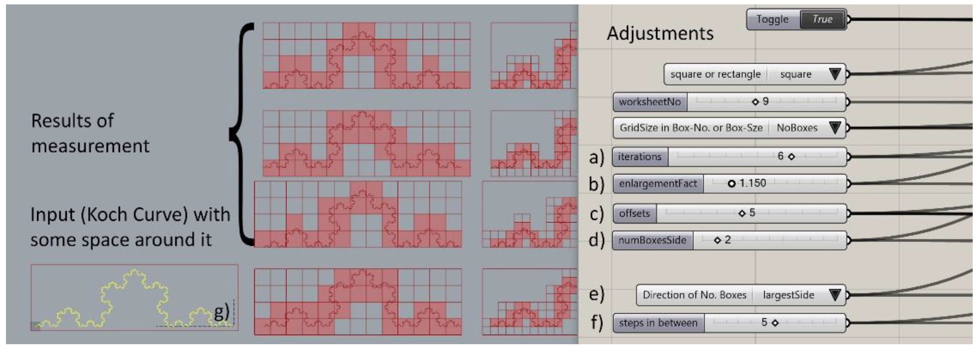
Figure 1. Box-counting with graphic macro programming in Grasshopper®.
Fractalfract 05 00244 g001
Figure 2. Box-counting with FRACAM.
Fractalfract 05 00244 g002
Figure 3. Calculation of intersection points on the orthogonal grid derived from original points.
Fractalfract 05 00244 g003
Figure 4. Calculation of distinct gradients based on local maxima within a given range.
Fractalfract 05 00244 g004
Figure 5. Steps of an up to date gradient analysis.
Fractalfract 05 00244 g005
Figure 6. Hilbert Curve, measurement with 7 iterations showing flattening of the data curve.
Fractalfract 05 00244 g006
Figure 7. (a) Hilbert Curve without offsets; (b) Hilbert Curve with 3 offsets; (c) Koch Curve without offsets; (d) Koch Curve with 3 offsets.
Fractalfract 05 00244 g007
Figure 8. Results with pre-defined settings showing the difference for 1.1, 1.15 and 1.2% enlargement factor, with (a) showing the medians and (b) showing the results for only smallest number of covering boxes.
Fractalfract 05 00244 g008
Figure 9. Test-Cases (from left to right: TestFile-A, TestFile-B, TestFile-C and TestFile-D.
Fractalfract 05 00244 g009
Figure 10. Results of measurement of the test cases.
Fractalfract 05 00244 g010
Figure 11. Data curve with the straightest part in green ( D B   = 1.3182 and R 2   = 0.996).
Fractalfract 05 00244 g011
Figure 12. Analyzed buildings without scale: (a) Robie House, street view with and without window design, FL Wright, 1908, (b) House Steiner, north, east, south, west view, Loos, 1910, (c) House Scheu, north, east, south view, Loos, 1913, (d) Villa Schwob, north-east, north-west, southeast, south-west, Le Corbusier, 1916, (e) House Mandl, Loos, north, east, south, west view, 1916, (f) Villa Savoye, north, east, south, west view, Le Corbusier, 1928.
Fractalfract 05 00244 g012
Figure 13. Kink in the data curve between the range of larger and smaller box sizes for House Mandl.
Fractalfract 05 00244 g013
Figure 14. Box-plot of measurement series using values of straight data curve. The value in the box plot gives the median, the percentage at the bottom gives the interquartile range in relation to the value two.
Fractalfract 05 00244 g014
Figure 15. Comparison Main Design and entire design (including e.g., frames of windows).
Fractalfract 05 00244 g015
Figure 16. Comparison of previous measurements (Lorenz 2014) of House Mandl top: (a,b) with current method, bottom: (c,d), with (a,c) giving the box plot of D B and (b,d) giving the ranges of box sizes in relation to the building height.
Fractalfract 05 00244 g016
Figure 17. Comparison D B of smallest number of covered boxes and the median.
Fractalfract 05 00244 g017
Figure 18. Box plot with median of the differential box-counting method of 23 exterior images, 17 detail images and 31 interior images of Robie House.
Fractalfract 05 00244 g018
Table 1. Calculation of the box sizes depending on the building height and the distance for the north view of House Steiner.
House Steiner:
North Elevation
Angles:18°27°45°
Approximate distances:40.50 m25.80 m13.20 m
Distance
corresponds to:
OverviewOverview with environmentSingle parts
0°10′11.80 cm7.50 cm3.85 cm
1°00′0.85 m0.50 m0.25 m
7°26′6.35 m3.60 m1.75 m
10°00′8.55 m4.85 m2.35 m
Publisher’s Note: MDPI stays neutral with regard to jurisdictional claims in published maps and institutional affiliations.