Article

Electrical Circuits RC, LC, and RLC under Generalized Type Non-Local Singular Fractional Operator

1
Department of Mathematics, Science Faculty, Firat University, Elazig 23119, Turkey
2
Department of Medical Research, China Medical University Hospital, China Medical University, Taichung 406040, Taiwan
*
Author to whom correspondence should be addressed.
Fractal Fract. 2021, 5(1), 9; https://doi.org/10.3390/fractalfract5010009
Submission received: 25 November 2020 / Revised: 7 January 2021 / Accepted: 8 January 2021 / Published: 12 January 2021
(This article belongs to the Special Issue Fractional Calculus and Special Functions with Applications)

Abstract

:
The current study is of interest when performing a useful extension of a crucial physical problem through a non-local singular fractional operator. We provide solutions that include three arbitrary parameters α , ρ , and γ for the Resistance-Capacitance (RC), Inductance-Capacitance (LC), and Resistance-Inductance-Capacitance (RLC) electric circuits utilizing a generalized type fractional operator in the sense of Caputo, called non-local M-derivative. Additionally, to keep the dimensionality of the physical parameter in the proposed model, we use an auxiliary parameter. Owing to the fact that all solutions depend on three parameters unlike the other solutions containing one or two parameters in the literature, the solutions obtained in this study have more general results. On the other hand, in order to observe the advantages of the non-local M-derivative, a comprehensive comparison is carried out in the light of experimental data. We make this comparison for the RC circuit between the non-local M-derivative and Caputo derivative. It is clearly shown on graphs that the fractional M-derivative behaves closer to the experimental data thanks to the added parameters α , ρ , and γ .

1. Introduction

Fractional derivatives and integrals including non-integer order are the natural generalizations of the traditional counterparts. Studies of fractional calculus in recent years have attracted considerable attention due to its advantages for modeling in various areas of science and engineering. As a result of defining non-integer order derivatives by means of integral, the non-locality property is one of its major advantages. Hence, the fractional derivatives involve data about the state variable at earlier points, and so they have a memory effect, which is useful to describe and comprehend the behavior of the complex and dynamic system. Moreover, there exist various fractional derivative and integral definitions in the literature. Accordingly, one of the main difficulties encountered in the fractional calculus is choosing an appropriate definition of the fractional operator for the problem under investigation. The Riemann–Liouville (RL) and Caputo fractional operators possess an important place in understanding the essence of fractional calculus. In particular, the Caputo fractional derivative is preferred as it is a powerful mathematical tool in application. The capabilities of the non-integer order derivatives and integrals have been shown in several rigorous studies such as the tautochrone problem, diffusion equation, control theory, models in physics, economy, biology, etc. On the other hand, some authors have proposed modified or generalized type RL and Caputo operators. It should also be mentioned that many fractional operator definitions are derived from the approach in [1]: Fractional derivative of a function with respect to (wrt) another function. Katugampola in [2] introduced a generalized-type fractional operator based on the fractional derivative of a function wrt another function. Furthermore, the authors in [3] introduced a non-local singular fractional derivative and integral by utilizing the same approach. This generalized-type fractional derivative called non-local M-derivative in the sense of Caputo is defined by:
M D α , ρ , γ φ ( t ) = Γ ( γ + 1 ) n α Γ ( n α ) ρ n α 1 a t ( t a ) ρ ( ξ a ) ρ n α 1 M D n , ρ , γ φ ( ξ ) d ξ ( ξ a ) 1 ρ ,
where α C , n = R e ( α ) + 1 , γ > 0 , and M D n , ρ , γ ( . ) is the local derivative as can be seen in [4]. In [3], the Laplace transform of the Caputo type fractional M-derivative we utilize to solve the proposed model is as follows:
L ρ , γ { M D n α , ρ , γ φ ( t ) } ( s ) = s α L ρ , γ { φ ( t ) } s α 1 φ ( a ) s α 2 M D ρ , γ φ ( a ) s α n + 1 M D ( n 2 ) ρ , γ φ ( a ) s α n M D ( n 1 ) ρ , γ φ ( a ) .
In a similar way, in [5], the authors presented a proportional-type non-local singular fractional operator under the local proportional derivative, which is formed by using control theory. With the help of this local derivative, novel fractional operators called proportional Caputo and constant proportional Caputo was defined in [6].
The existence of several fractional derivative and integral definitions allow us to employ the most appropriate definition for the problem addressed in order to obtain more precise results. Although many of these various definitions are quite similar, their physical interpretations may differ. It is widely known that some crucial physical properties may not be observed in classical models. In other words, such dissipative impacts on the electrical components like resistance, capacitance, and inductance as ohmic friction, non-linearity, thermal memory, etc. are not taken into account by means of the traditional approach. Consequently, there exist various physical problems handled by non-local fractional operators to capture the advantages of new generation non-integer order operators. One of the most important of the above-mentioned problems is the electrical circuits model. In [7], Gomez et al. implemented the electrical circuits with respect to the non-integer order operators to reach the analytical and numerical solutions of the proposed model, including the arbitrary parameters. In addition, the fractional Resistance-Capacitance (RC) and Resistance-Inductance-Capacitance (RLC) circuits were studied by employing some kinds of fractional operators with singular or non-singular kernels in [8]. In [9], the authors introduced the circuit elements like RC, RL, and LC via a new type non-local non-singular fractional operator under experimental data obtained from an electronic laboratory at CENIDET. The same model is investigated in [10] with a detailed comparative analysis between RL and RC circuits by means of non-singular fractional derivatives. The authors in [11] analyzed the model mentioned with the help of the generalized fractional derivative introduced by Katugampola. Moreover, the authors in [12] presented the RC, LC, and RLC circuits by employing a local-based derivative, and they obtained the analytical and numerical results. Hence, motivated by all these studies, we introduce more general solutions with the help of a generalized-type non-local singular fractional operator involving three arbitrary parameters introduced by Acay et al. in [3]. For some applications and beneficial information on fractional calculus, we refer the reader to [13,14,15,16,17,18,19,20,21,22,23,24,25].
The structure of the present paper is constituted as follows: In Section 2, the solutions of fractional RC, LC, and RLC electrical circuits are presented with various visual results and comprehensive interpretation. Then, in Section 3, we show a comparison between two efficient operators under an experimental data with some graphs and mention the crucial conclusions of our study.

2. Fractional Electrical Circuits

In this section, we present the RC and RLC electrical circuit including constant, exponential, and periodic sources. The fractional solutions are obtained by means of the non-local singular M-derivative containing three parameters α , ρ , and γ . Hence, we get the generalized version of the solutions obtained in the literature. The main purpose is to perform an extension of the ordinary differential equations to the fractional version via a non-local singular generalized derivative. On the other hand, preserving the physical dimensionality of the non-integer order operator is crucial in the application. In pure mathematics, generally, the integer-order derivative is replaced with non-integer order ones but this is not enough for physical problems and some applications in engineering. Therefore, dimensional modification is required for the fractional case. For this purpose, we employ the auxiliary parameter σ for the non-local fractional M-derivative in the sense of Caputo as follows:
d d t σ α ρ 1 M D α , ρ , γ ,
and
d 2 d t 2 σ 2 ( α ρ 1 ) M D α , ρ , γ ,
where α , ρ , and γ are arbitrary parameters, and the dimensionality of σ is the second (s). Hence, we employ this approach in order to get the solutions of the fractional electrical circuits with the help of the Caputo-type M-derivative [9,19,26].

2.1. Fractional RC Electrical Circuits under Non-Local M-Derivative in the Sense of Caputo

The RC series circuit differential equation under Kirchhoff’s law can be expressed by the non-local M-derivative in the sense of Caputo considering the relations Equations (3) and (4) as below:
σ α ρ 1 M D α , ρ , γ V c ( t ) + 1 ω V c ( t ) = 1 ω e ( t ) ,
where ω = R C is the time constant, R represents the resistance, C symbolizes the capacitance, the voltage on the capacitor is expressed by the function V c ( t ) , and e ( t ) is the source voltage. On the other hand, while σ 1 α ρ / R C is fractional time constant, 1 / R C is a traditional time constant. It should be noted that normally the dimension of the non-local M-derivative operator is ( t i m e ) α ρ (the parameter γ does not affect the dimension), but under favor of the term σ α ρ 1 , we eliminate the dimension mismatch physically.
Now, let us solve the Equation (5) with the help of the Laplace transform of the non-local fractional M-derivative under three main case with different types of sources as follows:
Case 1. (Constant source). If we consider e ( t ) = e 0 , V c ( 0 ) = V 0 ( V 0 > 0 ), we can rearrange Equation (5) as:
M D α , ρ , γ V c ( t ) + σ 1 α ρ ω V c ( t ) = σ 1 α ρ ω e 0 .
Applying LT of the non-local M-derivative in the Caputo sense, we have:
L ρ , γ { M D α , ρ , γ V c ( t ) } + σ 1 α ρ ω L ρ , γ { V c ( t ) } = L ρ , γ σ 1 α ρ ω e 0 ,
s α L ρ , γ { V c ( t ) } s α 1 V c ( 0 ) + σ 1 α ρ ω L ρ , γ { V c ( t ) } = e 0 σ 1 α ρ s ω ,
after some arrangements, one can get:
L ρ , γ { V c ( t ) } = V 0 s α 1 s α + σ 1 α ρ ω + e 0 σ 1 α ρ ω 1 s s α + σ 1 α ρ ω ,
hence if we take the inverse LT of Equation (9), we reach the following solution:
V c ( t ) = V 0 E α σ 1 α ρ ω Γ ( γ + 1 ) t ρ ρ α + e 0 1 E α σ 1 α ρ ω Γ ( γ + 1 ) t ρ ρ α ,
where E α ( . ) is the Mittag–Leffler function.
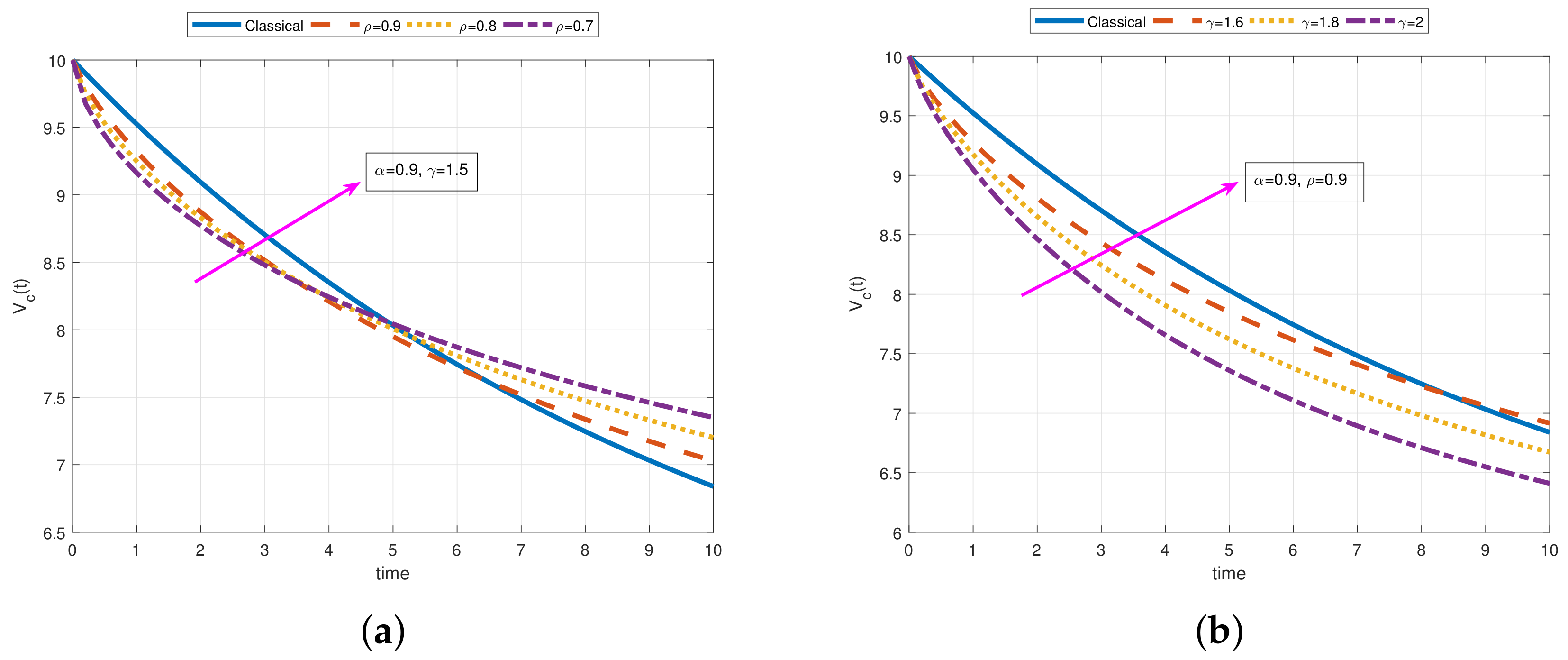
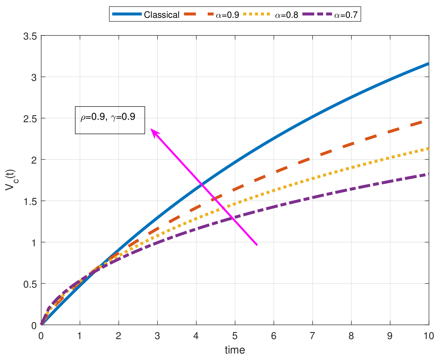
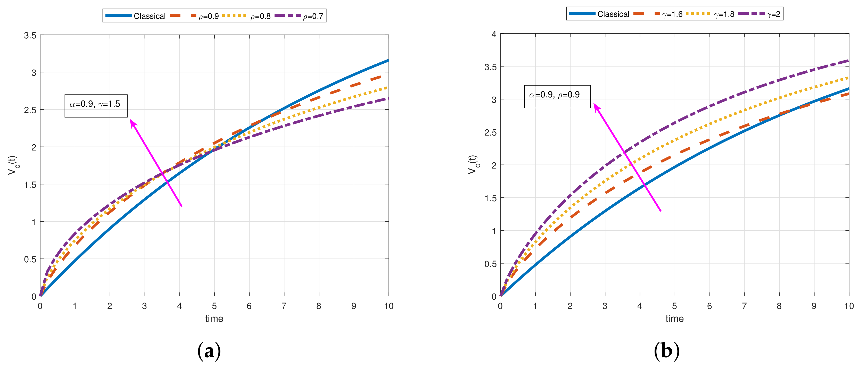
It can be seen that the fractional solution follows exponential dynamics if α , ρ , and γ are closer to 1. In Figure 1 and Figure 2 we show the plot for Case 1 (constant source) when R = 1 Ω , C = 10 F, e 0 = 5 V, and V c ( 0 ) = 10 V, and in Figure 3 and Figure 4, we use the values R = 1 Ω , C = 10 F, e 0 = 5 V, and V c ( 0 ) = 0 V. We observe the behavior of voltage across the capacitor in the RC circuit for e ( t ) = e 0 in Figure 1, Figure 2, Figure 3 and Figure 4 when α changes; α = 1 , 0.9 , 0.8 , 0.7 , ρ = 0.9 , and γ = 0.9 , when ρ changes; ρ = 1 , 0.9 , 0.8 , 0.7 , α = 0.9 , and γ = 1.5 , and when γ changes; γ = 1 , 1 , 6 , 1.8 , 2 , α = 0.9 , and ρ = 0.9 . In this way, the impact of the parameters α , ρ , and γ can clearly by observed on the solutions curves separately. On the other hand, in Figure 1, we observe that for the small values of α , the solution curve tends to stabilize in less time with exponential behavior. However for a classical case (when α = 1 , ρ = 1 , and γ = 1 ) it stabilizes in longer time. In Figure 2a, we see similar behavior in the solutions curves when ρ changes. However, the effect of the parameter γ is different from the effect of the parameters α and ρ as can be seen in Figure 2b and Figure 4b. It can be observed that for smaller values of γ , the solution curve approaches to stabilize in a longer time. Moreover, in Figure 1 and Figure 2, one can see that the solution curves are exponentially decreasing, and in Figure 3 and Figure 4, the exponentially increasing overdamped system.
Case 2. (Exponential source). Let e ( t ) = e 0 e λ Γ ( γ + 1 ) t ρ ρ , V c ( 0 ) = V 0 ( V 0 > 0 ). Then we can rewrite the Equation (5) as follows:
M D α , ρ , γ V c ( t ) + σ 1 α ρ ω V c ( t ) = σ 1 α ρ ω e 0 e λ Γ ( γ + 1 ) t ρ ρ .
If we take the LT of the Equation (11), we have:
L ρ , γ { M D α , ρ , γ V c ( t ) } + σ 1 α ρ ω L ρ , γ { V c ( t ) } = e 0 σ 1 α ρ ω L ρ , γ e λ Γ ( γ + 1 ) t ρ ρ ,
s α L ρ , γ { V c ( t ) } s α 1 V c ( 0 ) + σ 1 α ρ ω L ρ , γ { V c ( t ) } = e 0 σ 1 α ρ ω ( s + λ ) ,
L ρ , γ { V c ( t ) } = e 0 σ 1 α ρ ω 1 ( s + λ ) s α + σ 1 α ρ ω + V 0 s α s s α + σ 1 α ρ ω ,
applying the inverse LT and the convolution theorem, we can obtain the solution as:
V c ( t ) = V 0 E α σ 1 α ρ ω Γ ( γ + 1 ) t ρ ρ α + e 0 σ 1 α ρ ω Γ ( γ + 1 ) 0 t Γ ( γ + 1 ) t ρ ρ Γ ( γ + 1 ) τ ρ ρ α 1 × E α , α σ 1 α ρ ω Γ ( γ + 1 ) t ρ ρ Γ ( γ + 1 ) τ ρ ρ α × exp λ Γ ( γ + 1 ) τ ρ ρ τ ρ 1 d τ .
Case 3. (Oscillatory source). If we suppose that e ( t ) = e 0 cos θ Γ ( γ + 1 ) t ρ ρ , V c ( 0 ) = V 0 ( V 0 > 0 ), then we can write:
M D α , ρ , γ V c ( t ) + σ 1 α ρ ω V c ( t ) = σ 1 α ρ ω e 0 cos θ Γ ( γ + 1 ) t ρ ρ .
Taking LT of the Equation (16), we readily have:
L ρ , γ { M D α , ρ , γ V c ( t ) } + σ 1 α ρ ω L ρ , γ { V c ( t ) } = e 0 σ 1 α ρ ω L ρ , γ cos θ Γ ( γ + 1 ) t ρ ρ ,
s α L ρ , γ { V c ( t ) } s α 1 V c ( 0 ) + σ 1 α ρ ω L ρ , γ { V c ( t ) } = e 0 σ 1 α ρ s ω ( θ 2 + s 2 ) ,
L ρ , γ { V c ( t ) } = e 0 σ 1 α ρ ω s ( θ 2 + s 2 ) s α + σ 1 α ρ ω + V 0 s α s s α + σ 1 α ρ ω ,
after applying inverse LT transform and convolution theorem, one can reach the solution below:
V c ( t ) = V 0 E α σ 1 α ρ ω Γ ( γ + 1 ) t ρ ρ α + e 0 σ 1 α ρ ω Γ ( γ + 1 ) 0 t Γ ( γ + 1 ) t ρ ρ Γ ( γ + 1 ) τ ρ ρ α 1 × E α , α σ 1 α ρ ω Γ ( γ + 1 ) t ρ ρ Γ ( γ + 1 ) τ ρ ρ α × cos θ Γ ( γ + 1 ) t ρ ρ τ ρ 1 d τ .
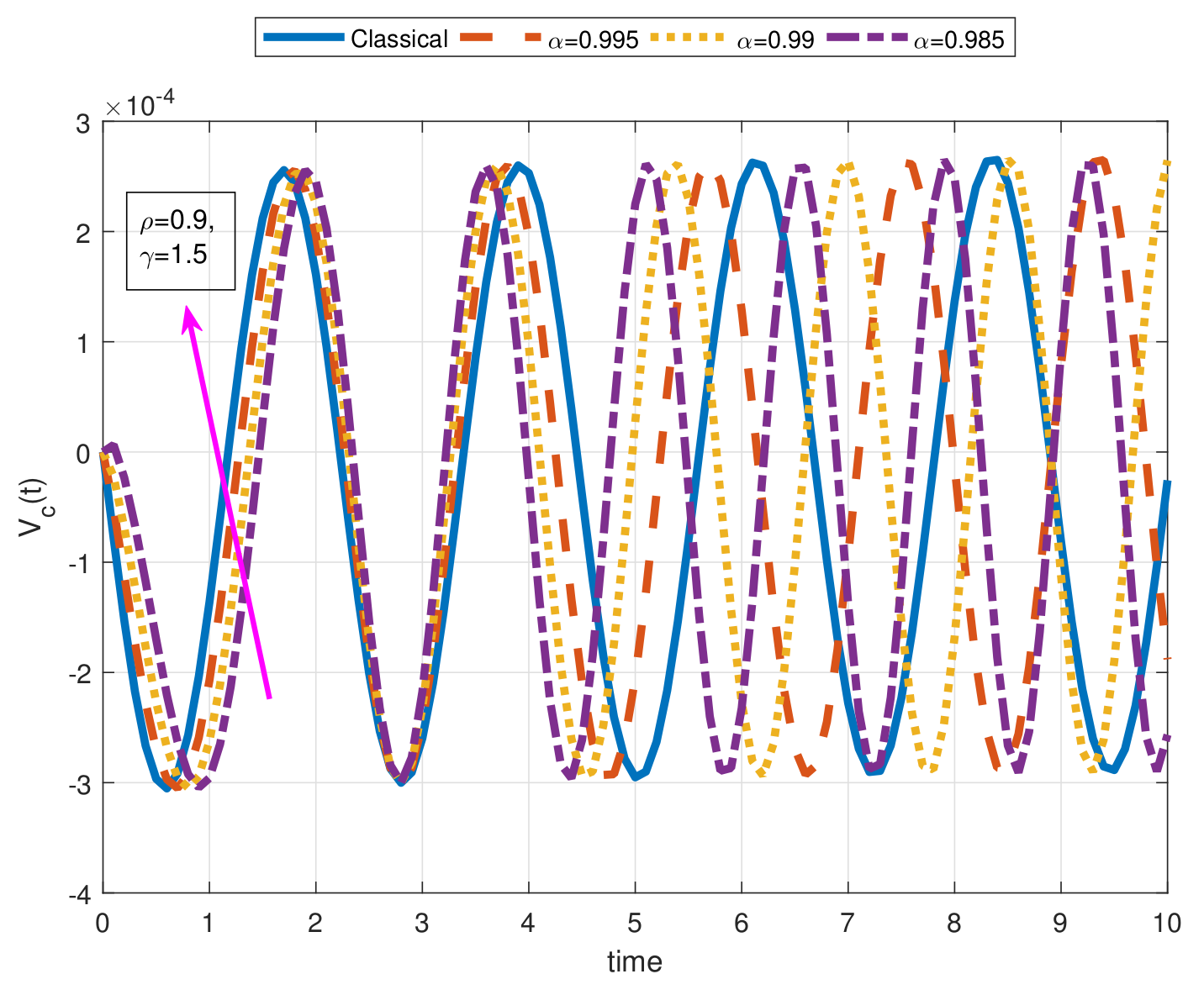
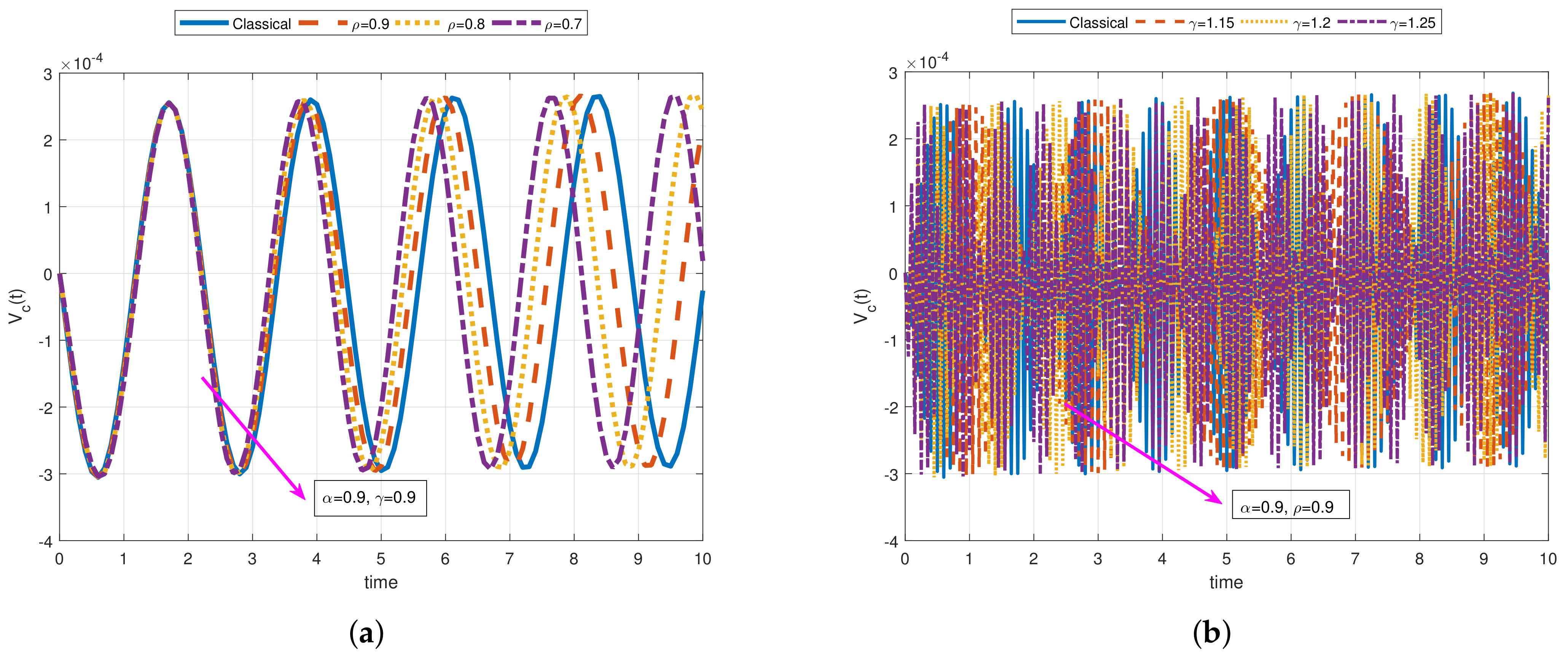
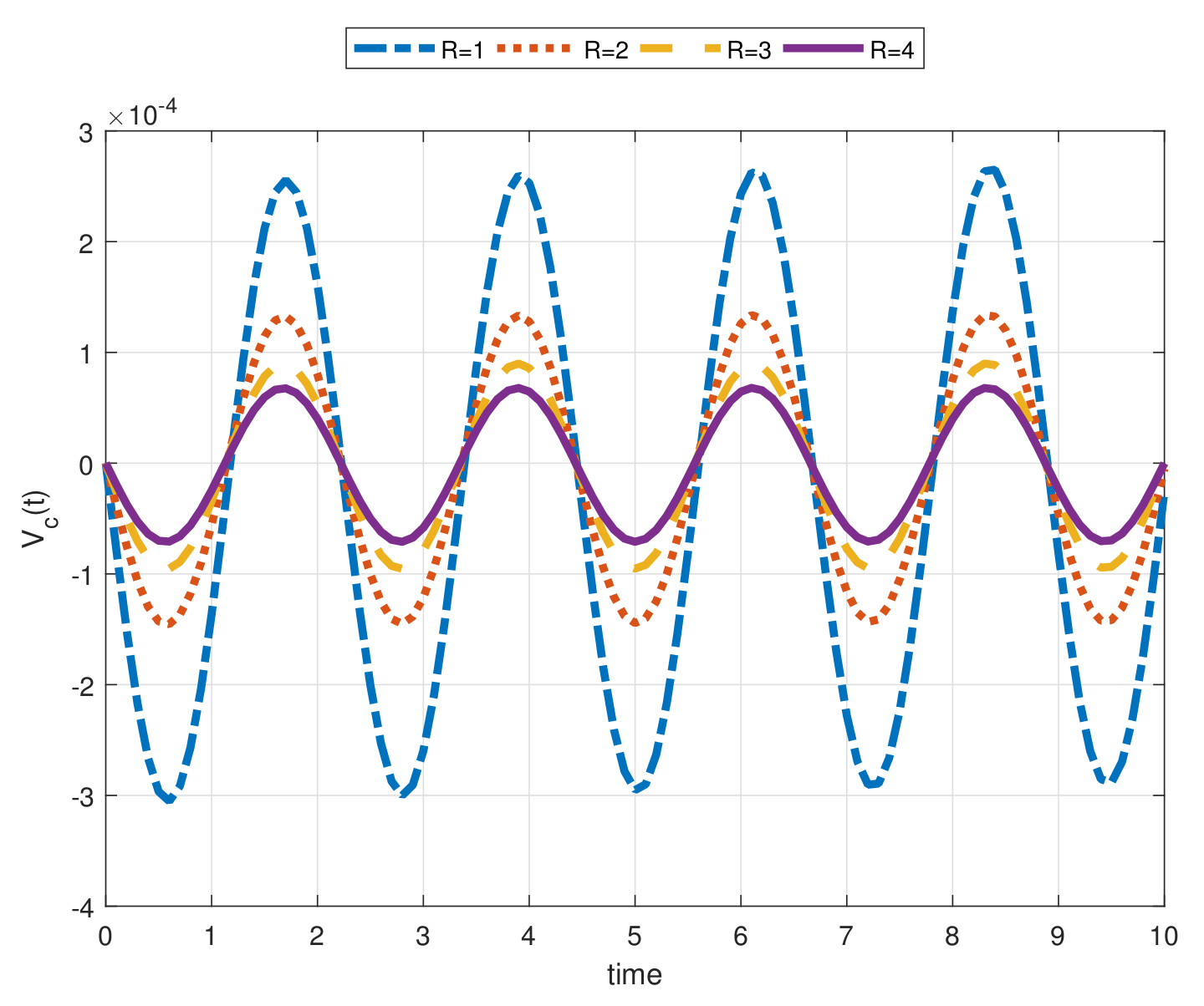
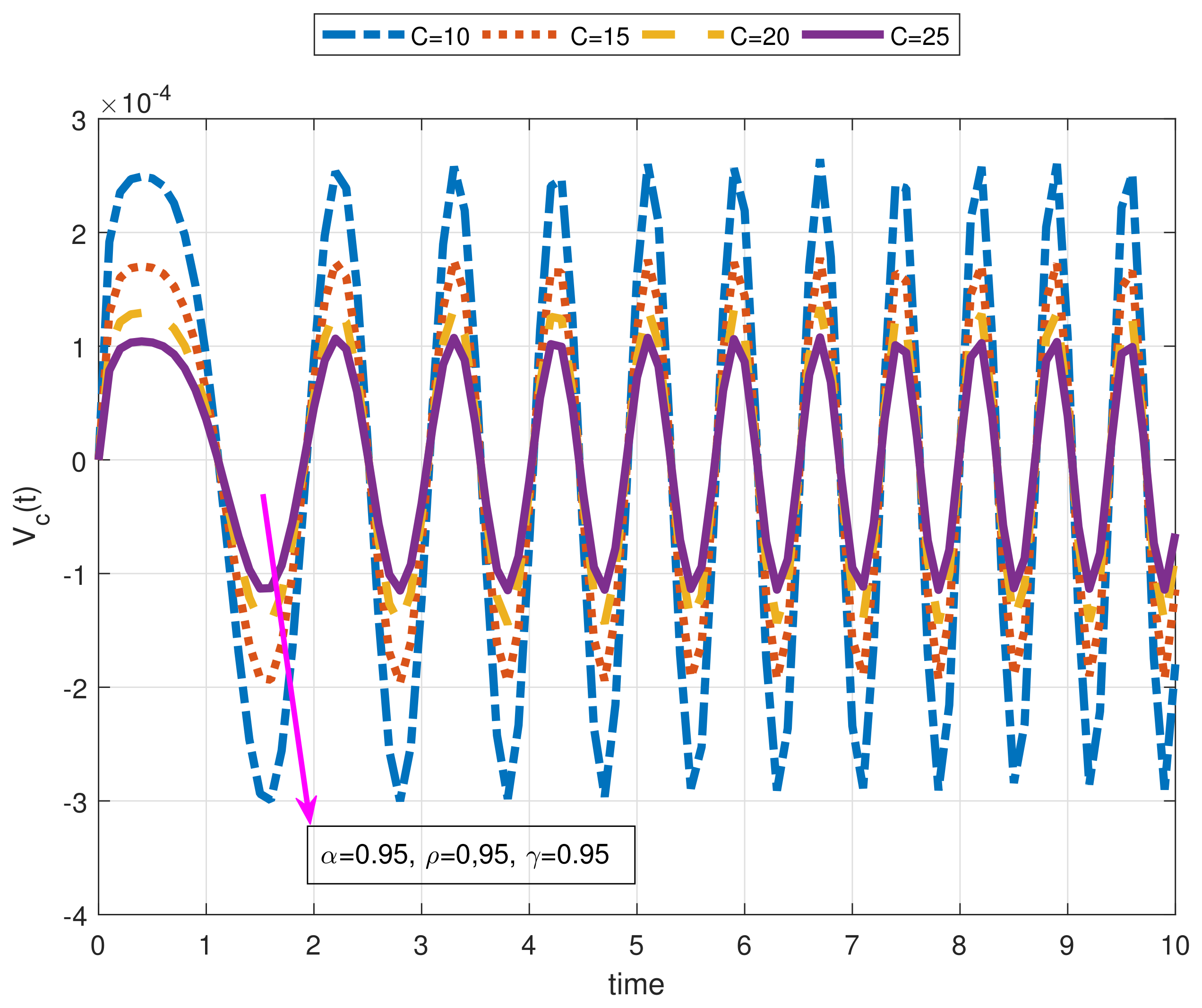
For oscillatory source case involving the angular frequency θ ( e ( t ) = e 0 cos ( θ t ) ), we present Figure 5, Figure 6, Figure 7 and Figure 8 for various values of the α , γ , and ρ when R = 1 Ω , C = 10 F, e 0 = 10 V, θ = 60 Hz, and V c ( 0 ) = 10 V. We should note that in the case of standard approach α = 1 , ρ = 1 , and γ = 1 , some losses which are based on the ohmic friction, temperature, and so on are not considered. However, the non-integer order approach enables us to examine the proposed physical problem more precisely. It is also seen that the solutions curves with different values of α , ρ , and γ are below or under the traditional solution curve for a time. This situation varies for different arbitrary parameter values. On the other hand, we can see the behavior of voltage across the capacitor in the RC circuit for e ( t ) = e 0 cos Γ ( γ + 1 ) t ρ ρ in Figure 5, Figure 6, Figure 7 and Figure 8 when α changes; α = 1 , 0.995 , 0.99 , 0.985 , ρ = 0.9 , and γ = 1.5 , when ρ changes; ρ = 1 , 0.9 , 0.8 , 0.7 , α = 0.9 , and γ = 0.9 , and when γ changes; γ = 1 , 1 , 15 , 1.2 , 1.25 , α = 0.9 , and ρ = 0.9 . Furthermore, in Figure 5 and Figure 6, we can also observe that the period may change under the fractional-order derivative, the apparent motion of the solution curves obtained by employing the arbitrary order may appear more complicated, and the extremes of the solution function can change for different values of fractional order. In addition, for different values R and C, the wave height and length change in Figure 7 and Figure 8, respectively.

2.2. Fractional Inductance-Capacitance (LC) Electrical Circuits under Non-Local M-Derivative in the Sense of Caputo

If the law of Kirchhoff is applied, then the LC series circuit differential equation under the relations Equations (3) and (4) can be presented by:
σ 2 ( α ρ 1 ) M D 2 α , ρ , γ I ( t ) + 1 η I ( t ) = C η e ( t ) ,
where η = L C , L represents the inductance, the capacitance is denoted by C, and e ( t ) stands for source voltage. Now, we solve the above-stated equation by employing LT of the non-local fractional M-derivative with three case including different sources as below:
Case 1. (Constant source). Supposing e ( t ) = e 0 , I ( 0 ) = I 0 ( I 0 > 0 ), M D æ , f l I ( 0 ) = 0 , we can express the Equation (21) as:
M D 2 α , ρ , γ I ( t ) + σ 2 ( 1 α ρ ) η I ( t ) = C σ 2 ( 1 α ρ ) η e 0 ,
where η = L C and C is the capacitance. If we apply the LT to Equation (22), we have:
L ρ , γ { M D 2 α , ρ , γ I ( t ) } + σ 2 ( 1 α ρ ) η L ρ , γ { I ( t ) } = L ρ , γ C σ 2 ( 1 α ρ ) e 0 η ,
s α L ρ , γ { I ( t ) } s α 1 I ( 0 ) s α 2 M D æ , f l I ( 0 ) + σ 2 ( 1 α ρ ) η L ρ , γ { I ( t ) } = C σ 2 ( 1 α ρ ) e 0 s η ,
L ρ , γ { I ( t ) } = I 0 s α 1 s α + σ 2 ( 1 α ρ ) η + C σ 2 ( 1 α ρ ) e 0 η 1 s s α + σ 2 ( 1 α ρ ) η ,
and if we apply the inverse LT to the Equation (25), we reach the following solution:
I ( t ) = I 0 E α σ 2 ( 1 α ρ ) η Γ ( γ + 1 ) t ρ ρ α + C e 0 1 E α σ 2 ( 1 α ρ ) η Γ ( γ + 1 ) t ρ ρ α .
1 η = 1 L C in Equation (21) represents the natural angular frequency, and the initial charge of the capacitor is denoted by I 0 . In Figure 9, A and B correspond to Equation (26) with constant source when I ( 0 ) = 0 and I ( 0 ) = 10 , respectively. These plots are obtained when α = 1 , 0.9 , 0.8 , 0.7 , ρ = 1 , 0.9 , 0.8 , 0.7 , and γ = 0.7 . The system is exponentially increasing in A and exponentially decreasing in B. We see that the solution curve tends faster to the steady state for small values of α and ρ .
Case 2. (Exponential source). Let e ( t ) = e 0 e λ Γ ( γ + 1 ) t ρ ρ , I ( 0 ) = I 0 ( I 0 > 0 ), M D ρ , γ I ( 0 ) = 0 , then Equation (21) can be written as follows:
M D 2 α , ρ , γ I ( t ) + σ 2 ( 1 α ρ ) η I ( t ) = C σ 2 ( 1 α ρ ) η e 0 e λ Γ ( γ + 1 ) t ρ ρ ,
applying the LT to Equation (27), we have:
L ρ , γ { M D 2 α , ρ , γ I ( t ) } + σ 2 ( 1 α ρ ) η L ρ , γ { I ( t ) } = C σ 2 ( 1 α ρ ) e 0 η L ρ , γ { e λ Γ ( γ + 1 ) t ρ ρ } ,
s α L ρ , γ { I ( t ) } s α 1 I ( 0 ) s α 2 M D æ , f l I ( 0 ) + σ 2 ( 1 α ρ ) η L ρ , γ { I ( t ) } = C σ 2 ( 1 α ρ ) e 0 η ( s + λ ) ,
L ρ , γ { I ( t ) } = I 0 s α 1 s α + σ 2 ( 1 α ρ ) η + C σ 2 ( 1 α ρ ) e 0 η 1 ( s + λ ) s α + σ 2 ( 1 α ρ ) η ,
after taking inverse LT, one can attain the following solution:
I ( t ) = I 0 E α σ 2 ( 1 α ρ ) η Γ ( γ + 1 ) t ρ ρ α + C σ 2 ( 1 α ρ ) e 0 η Γ ( γ + 1 ) 0 t Γ ( γ + 1 ) t ρ ρ Γ ( γ + 1 ) τ ρ ρ α 1 × E α , α σ 2 ( 1 α ρ ) η Γ ( γ + 1 ) t ρ ρ Γ ( γ + 1 ) τ ρ ρ α × exp λ Γ ( γ + 1 ) τ ρ ρ τ ρ 1 d τ .
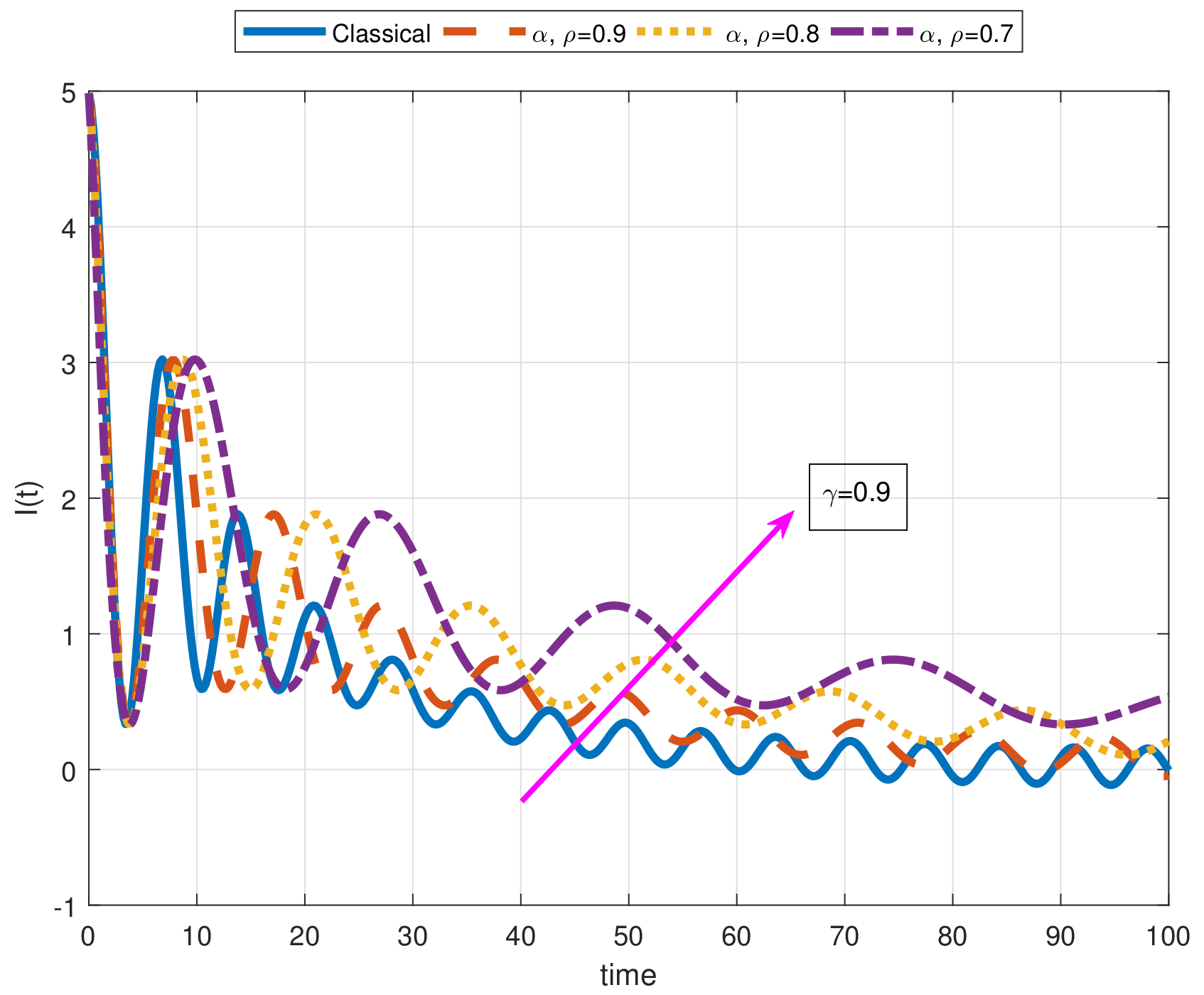
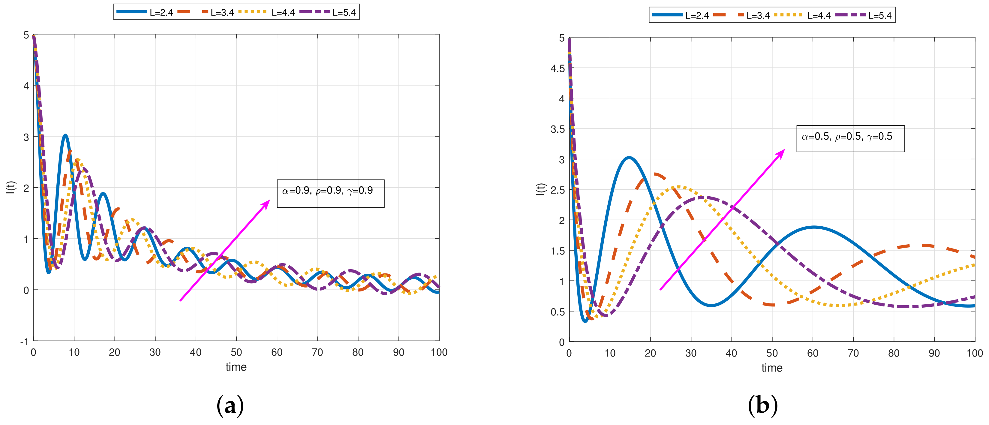
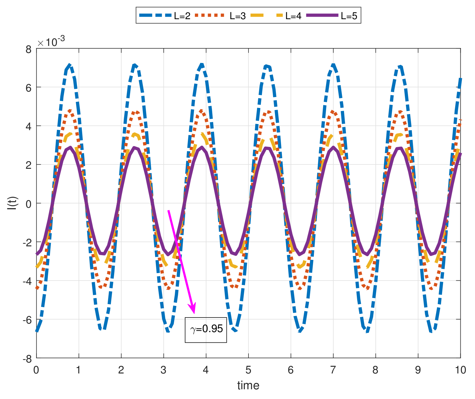
Figure 10 corresponds to solution Equation (31) including exponential source when α = 1 , 0.9 , 0.8 , 0.7 , ρ = 1 , 0.9 , 0.8 , 0.7 , γ = 0.9 , C = 0.5 F, L = 2.4 H, λ = 0.05 , e 0 = 5 V, and I ( 0 ) = 0 . From Figure 10 and Figure 11, we observe an oscillatory behavior and the effect of the parameters α , ρ , and γ on the function I ( t ) . Furthermore, in Figure 11 corresponding to I ( t ) with exponential source, the impact of arbitrary parameters when α = 0.9 , ρ = 0.9 , γ = 0.9 in A, and α = 0.5 , ρ = 0.5 , γ = 0.5 in B for L = 2.4 , 3.4 , 4.4 , 5.4 can clearly be seen. It is worth mentioning that in Figure 9 and Figure 10, having exponential behavior, while the classical solution function tends to stabilize slower, the fractional solution function with smaller values of α and ρ approach to stabilize in less time. On the other hand, one can see the oscillatory behavior underdamped system in Figure 10 and Figure 11. In Figure 12, the different values of the parameter L change the wave height critically.
Case 3. (Oscillatory source). Assuming that e ( t ) = e 0 cos θ Γ ( γ + 1 ) t ρ ρ , I ( 0 ) = I 0 ( I 0 > 0 ), and M D æ , f l I ( 0 ) = 0 , we present the Equation (21) in the following form:
M D 2 α , ρ , γ I ( t ) + σ 2 ( 1 α ρ ) η I ( t ) = C σ 2 ( 1 α ρ ) η e 0 cos θ Γ ( γ + 1 ) t ρ ρ ,
by applying the LT, we get:
L ρ , γ { M D 2 α , ρ , γ I ( t ) } + σ 2 ( 1 α ρ ) η L ρ , γ { I ( t ) } = C σ 2 ( 1 α ρ ) e 0 η L ρ , γ cos θ Γ ( γ + 1 ) t ρ ρ ,
s α L ρ , γ { I ( t ) } s α 1 I ( 0 ) s α 2 M D æ , f l I ( 0 ) + σ 2 ( 1 α ρ ) η L ρ , γ { I ( t ) } = C s σ 2 ( 1 α ρ ) e 0 η ( θ 2 + s 2 ) ,
L ρ , γ { I ( t ) } = I 0 s α 1 s α + σ 2 ( 1 α ρ ) η + C σ 2 ( 1 α ρ ) e 0 η s ( θ 2 + s 2 ) ( s α + σ 2 ( 1 α ρ ) η ) ,
and if we apply the inverse LT, then we get the solution below:
I ( t ) = I 0 E α σ 2 ( 1 α ρ ) η Γ ( γ + 1 ) t ρ ρ α + C σ 2 ( 1 α ρ ) e 0 η Γ ( γ + 1 ) 0 t Γ ( γ + 1 ) t ρ ρ Γ ( γ + 1 ) τ ρ ρ α 1 × E α , α σ 2 ( 1 α ρ ) η Γ ( γ + 1 ) t ρ ρ Γ ( γ + 1 ) τ ρ ρ α × cos θ Γ ( γ + 1 ) t ρ ρ τ ρ 1 d τ .
Figure 12 is plotted for the solution Equation (36) when L = 2 , 3 , 4 , 5 and γ = 0.95 .

2.3. Fractional RLC Electrical Circuits under Non-Local M-Derivative in the Sense of Caputo

The fractional RLC series circuit differential equation can be presented according to the non-local M-derivative as below:
σ 2 ( α ρ 1 ) M D 2 α , ρ , γ q ( t ) + C R δ σ α ρ 1 M D α , ρ , γ q ( t ) + 1 δ q ( t ) = C δ e ( t ) ,
where δ = L C , L denotes the inductance, the capacitance is represented by C, R stands for the resistance, and e ( t ) is the source voltage. Let us solve Equation (37) under the fractional non-local M-derivative with the help of the LT. We present three cases including different types of sources as follows:
Case 1. (Constant source). Assuming that e ( t ) = e 0 , q ( 0 ) = q 0 , and M D ρ , γ q ( 0 ) = 0 , we give Equation (37) the following form:
M D 2 α , ρ , γ q ( t ) + C R δ σ 1 α ρ M D α , ρ , γ q ( t ) + σ 2 ( 1 α ρ ) δ q ( t ) = C σ 2 ( 1 α ρ ) e 0 δ ,
by applying the LT of the Equation (38), then we attain:
L ρ , γ { M D 2 α , ρ , γ q ( t ) } + C R σ 1 α ρ δ L ρ , γ { M D α , ρ , γ q ( t ) } + σ 2 ( 1 α ρ ) δ L ρ , γ { q ( t ) } = L ρ , γ C σ 2 ( 1 α ρ ) e 0 δ ,
s α L ρ , γ { q ( t ) } s α 1 q ( 0 ) s α 2 M D ρ , γ q ( 0 ) + C R σ 1 α ρ δ s α L ρ , γ { q ( t ) } s α 1 q 0 + σ 2 ( 1 α ρ ) δ L ρ , γ { q ( t ) } = C σ 2 ( 1 α ρ ) e 0 s δ ,
L ρ , γ { q ( t ) } = q 0 s α 1 s α 1 + C R σ 1 α ρ δ + σ 2 ( 1 α ρ ) δ + q 0 C R σ 1 α ρ δ s α 1 s α 1 + C R σ 1 α ρ δ + σ 2 ( 1 α ρ ) δ + C σ 2 ( 1 α ρ ) e 0 δ 1 s s α 1 + C R σ 1 α ρ δ + σ 2 ( 1 α ρ ) δ ,
L ρ , γ { q ( t ) } = q 0 δ δ + C R σ 1 α ρ s α 1 s α + σ 2 ( 1 α ρ ) δ + C R σ 1 α ρ + q 0 C R σ 1 α ρ δ + C R σ 1 α ρ s α 1 s α + σ 2 ( 1 α ρ ) δ + C R σ 1 α ρ + C σ 2 ( 1 α ρ ) e 0 δ + C R σ 1 α ρ 1 s s α + σ 2 ( 1 α ρ ) δ + C R σ 1 α ρ ,
and by taking the inverse LT, we reach the solution as follows:
q ( t ) = q 0 δ δ + C R σ 1 α ρ E α σ 2 ( 1 α ρ ) δ + C R σ 1 α ρ Γ ( γ + 1 ) t ρ ρ α + q 0 C R σ 1 α ρ δ + C R σ 1 α ρ E α σ 2 ( 1 α ρ ) δ + C R σ 1 α ρ Γ ( γ + 1 ) t ρ ρ α + C σ 2 ( 1 α ρ ) e 0 δ + C R σ 1 α ρ 1 E α σ 2 ( 1 α ρ ) δ + C R σ 1 α ρ Γ ( γ + 1 ) t ρ ρ α .
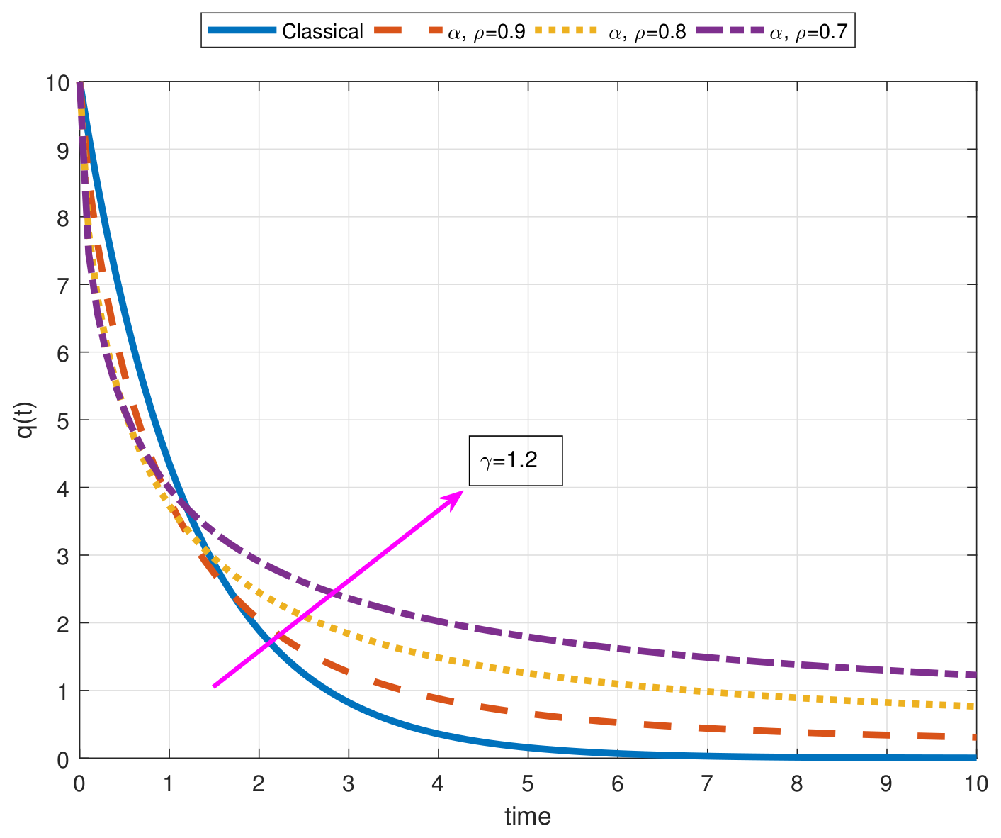
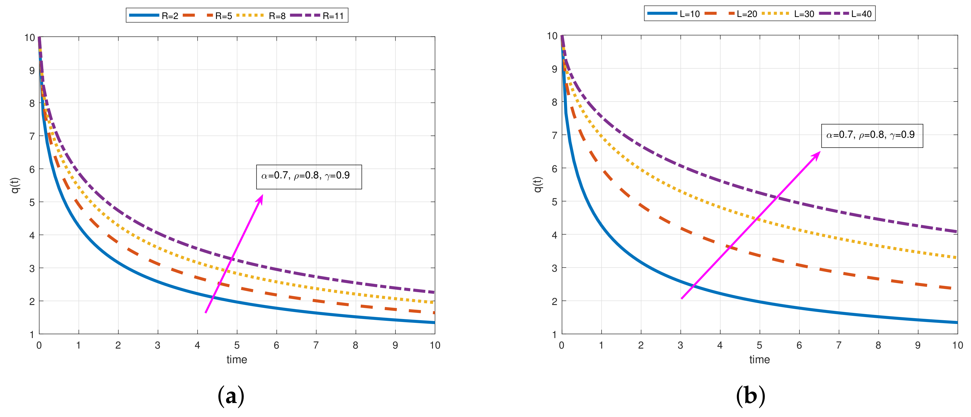
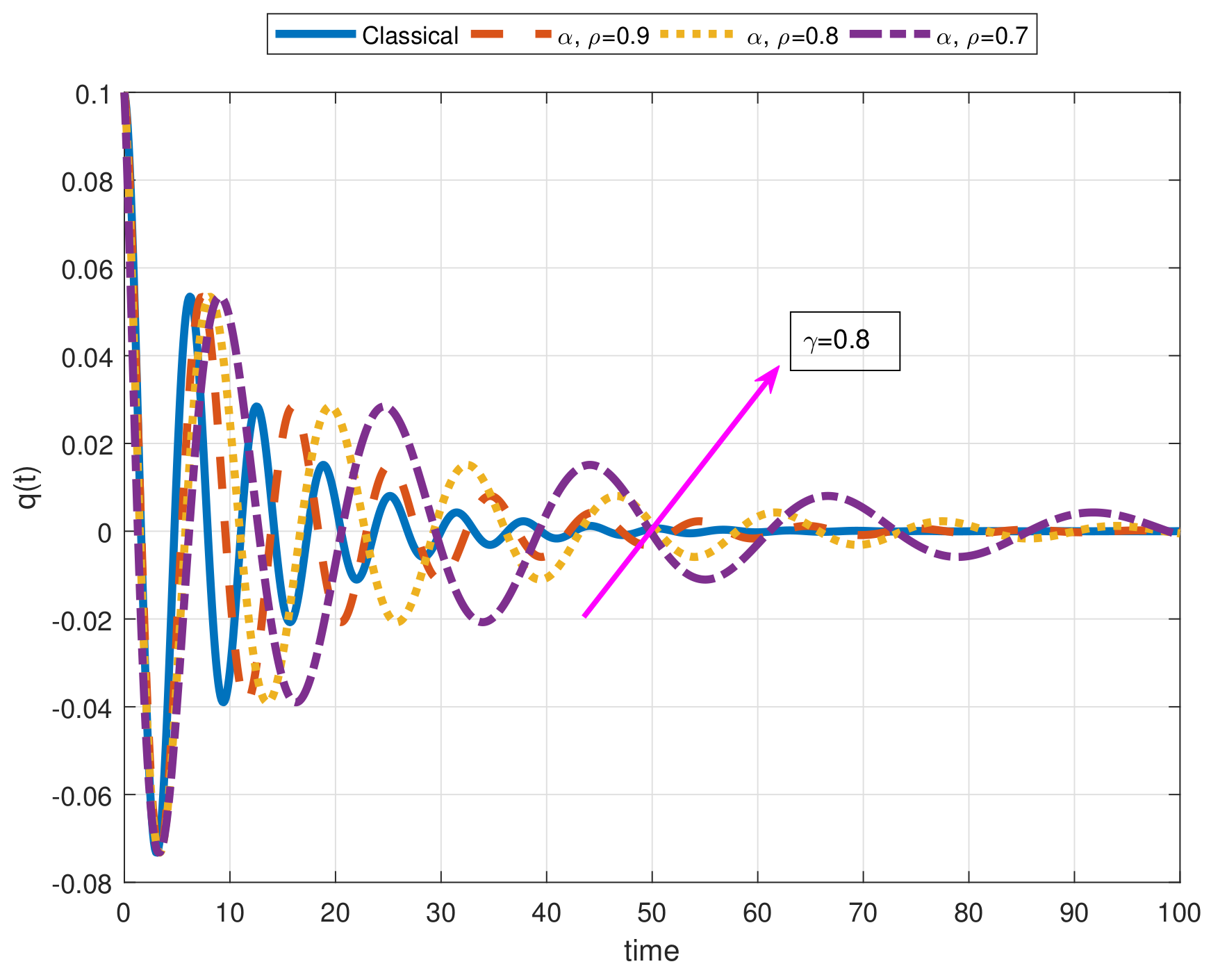
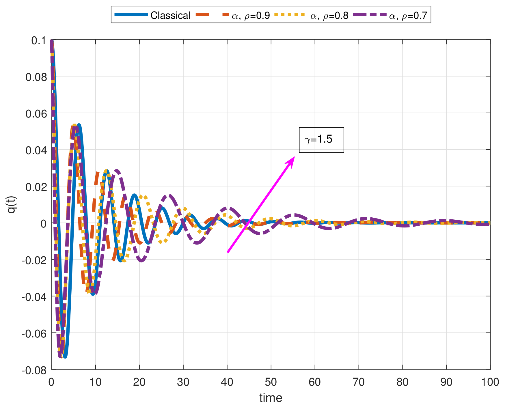
The plots for the solution Equation (43) is presented in Figure 13 and Figure 14. We show the behavior of the function q ( t ) with constant source when α = 1 , 0.9 , 0.8 , 0.7 , ρ = 1 , 0.9 , 0.8 , 0.7 , γ = 1.2 according to R = 2 Ω , L = 10 H, C = 0.1 F, e 0 = 5 V, q ( 0 ) = 10 , and M D α , ρ , γ q ( 0 ) = 0 . On the other hand, in Figure 14, one can see the solutions curves for some values of R and L when α = 0.7 , ρ = 0.8 , and γ = 0.9 . Moreover, Figure 13 and Figure 14 show exponential behavior when R and L change for different values of fractional-orders. It is clear that fractional-orders have the power to increase or decrease wavelength and height as can be seen in Figure 15 and Figure 16 showing oscillatory behavior under the damping system.
Case 2. (Exponential source). Let us assume that e ( t ) = e 0 e λ Γ ( γ + 1 ) t ρ ρ , q ( 0 ) = q 0 , and M D ρ , γ q ( 0 ) = 0 , we present Equation (37) as:
M D 2 α , ρ , γ q ( t ) + C R δ σ 1 α ρ M D α , ρ , γ q ( t ) + σ 2 ( 1 α ρ ) δ q ( t ) = C σ 2 ( 1 α ρ ) δ e 0 e λ Γ ( γ + 1 ) t ρ ρ ,
and taking the LT of the Equation (44), we can get:
L ρ , γ { M D 2 α , ρ , γ q ( t ) } + C R σ 1 α ρ δ L ρ , γ { M D α , ρ , γ q ( t ) } + σ 2 ( 1 α ρ ) δ L ρ , γ { q ( t ) } = C σ 2 ( 1 α ρ ) e 0 δ L ρ , γ { e λ Γ ( γ + 1 ) t ρ ρ } ,
s α L ρ , γ { q ( t ) } s α 1 q ( 0 ) s α 2 M D ρ , γ q ( 0 ) + C R σ 1 α ρ δ s α L ρ , γ { q ( t ) } s α 1 q 0 + σ 2 ( 1 α ρ ) δ L ρ , γ { q ( t ) } = C σ 2 ( 1 α ρ ) e 0 δ ( s + λ ) ,
L ρ , γ { q ( t ) } = q 0 δ δ + C R σ 1 α ρ s α 1 s α + σ 2 ( 1 α ρ ) δ + C R σ 1 α ρ + q 0 C R σ 1 α ρ δ + C R σ 1 α ρ s α 1 s α + σ 2 ( 1 α ρ ) δ + C R σ 1 α ρ + C σ 2 ( 1 α ρ ) e 0 δ + C R σ 1 α ρ 1 s + λ 1 s α + σ 2 ( 1 α ρ ) δ + C R σ 1 α ρ ,
q ( t ) = q 0 δ δ + C R σ 1 α ρ E α σ 2 ( 1 α ρ ) δ + C R σ 1 α ρ Γ ( γ + 1 ) t ρ ρ α + q 0 C R σ 1 α ρ δ + C R σ 1 α ρ E α σ 2 ( 1 α ρ ) δ + C R σ 1 α ρ Γ ( γ + 1 ) t ρ ρ α + C σ 2 ( 1 α ρ ) e 0 δ + C R σ 1 α ρ Γ ( γ + 1 ) 0 t Γ ( γ + 1 ) t ρ ρ Γ ( γ + 1 ) τ ρ ρ α 1 × E α , α σ 2 ( 1 α ρ ) δ + C R σ 1 α ρ Γ ( γ + 1 ) t ρ ρ Γ ( γ + 1 ) τ ρ ρ α × exp λ Γ ( γ + 1 ) τ ρ ρ τ ρ 1 d τ .
Figure 15 and Figure 16 show the behavior of the solution Equation (48) under the exponential source for some values of α and ρ when γ = 0.8 and γ = 1.5 , respectively. By deliberately choosing the α and ρ values the same on these two figures, we change the value of γ and clearly observe its effect on the system.
Case 3. (Oscillatory source). Supposing that e ( t ) = e 0 cos θ Γ ( γ + 1 ) t ρ ρ , q ( 0 ) = q 0 , and M D ρ , γ q ( 0 ) = 0 , we present Equation (37) as:
M D 2 α , ρ , γ q ( t ) + C R δ σ 1 α ρ M D α , ρ , γ q ( t ) + σ 2 ( 1 α ρ ) δ q ( t ) = C σ 2 ( 1 α ρ ) δ e 0 cos θ Γ ( γ + 1 ) t ρ ρ ,
by taking the LT of Equation (49), we attain the following relation:
L ρ , γ { M D 2 α , ρ , γ q ( t ) } + C R σ 1 α ρ δ L ρ , γ { M D α , ρ , γ q ( t ) } + σ 2 ( 1 α ρ ) δ L ρ , γ { q ( t ) } = C σ 2 ( 1 α ρ ) e 0 δ L ρ , γ cos θ Γ ( γ + 1 ) t ρ ρ ,
s α L ρ , γ { q ( t ) } s α 1 q ( 0 ) s α 2 M D ρ , γ q ( 0 ) + C R σ 1 α ρ δ s α L ρ , γ { q ( t ) } s α 1 q 0 + σ 2 ( 1 α ρ ) δ L ρ , γ { q ( t ) } = C σ 2 ( 1 α ρ ) e 0 δ s θ 2 + s 2 ,
L ρ , γ { q ( t ) } = q 0 δ δ + C R σ 1 α ρ s α 1 s α + σ 2 ( 1 α ρ ) δ + C R σ 1 α ρ + q 0 C R σ 1 α ρ δ + C R σ 1 α ρ s α 1 s α + σ 2 ( 1 α ρ ) δ + C R σ 1 α ρ + C σ 2 ( 1 α ρ ) e 0 δ + C R σ 1 α ρ s θ 2 + s 2 1 s α + σ 2 ( 1 α ρ ) δ + C R σ 1 α ρ ,
q ( t ) = q 0 δ δ + C R σ 1 α ρ E α σ 2 ( 1 α ρ ) δ + C R σ 1 α ρ Γ ( γ + 1 ) t ρ ρ α + q 0 C R σ 1 α ρ δ + C R σ 1 α ρ E α σ 2 ( 1 α ρ ) δ + C R σ 1 α ρ Γ ( γ + 1 ) t ρ ρ α + C σ 2 ( 1 α ρ ) e 0 δ + C R σ 1 α ρ Γ ( γ + 1 ) 0 t Γ ( γ + 1 ) t ρ ρ Γ ( γ + 1 ) τ ρ ρ α 1 × E α , α σ 2 ( 1 α ρ ) δ + C R σ 1 α ρ Γ ( γ + 1 ) t ρ ρ Γ ( γ + 1 ) τ ρ ρ α × cos θ Γ ( γ + 1 ) t ρ ρ τ ρ 1 d τ .

3. Comparative Analysis and Concluding Remarks

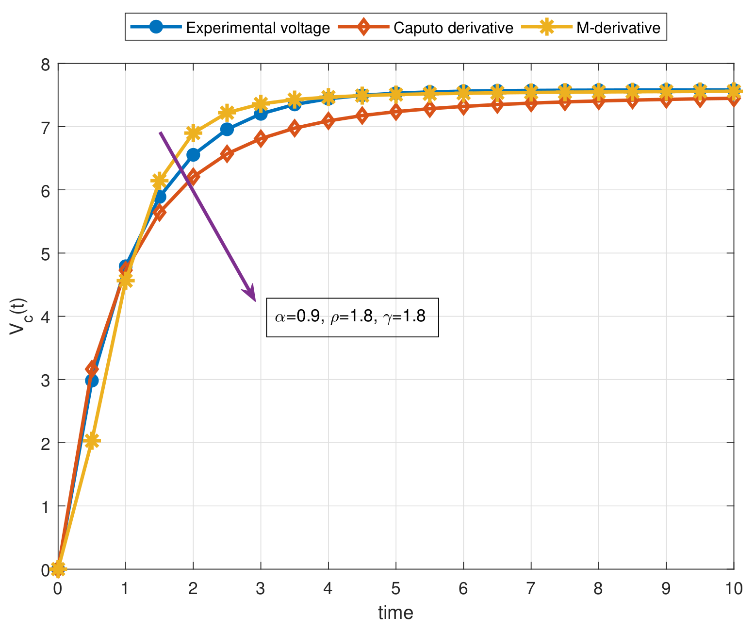
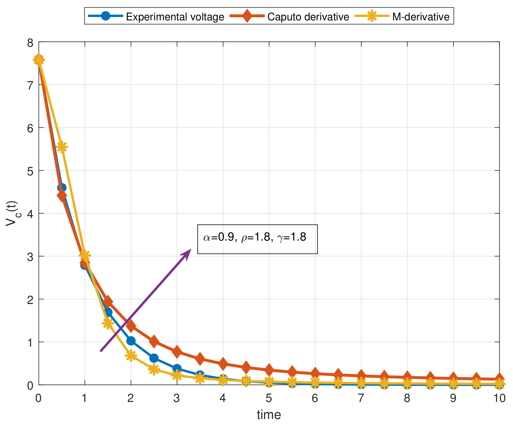
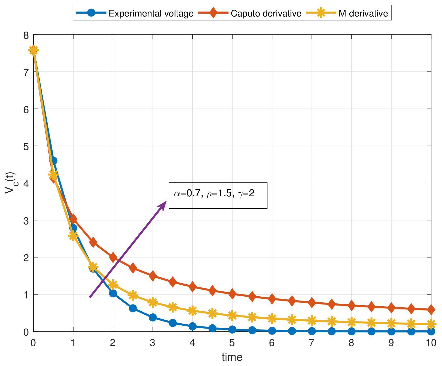
Here, we have performed a comparative analysis to observe the impact of the additional parameters inside the non-local fractional M-derivative. For this purpose, we have compared our results with the solution obtained via the Caputo operator in [8]. This comparison has been carried out for the RC circuit with constant source by employing the experimental data obtained from the electronic laboratory in CENIDET. The used experimental data is R = 10 Ω , C = 1000 F, e 0 = 7.58 , and V c ( 0 ) = 0 and for the second case, R = 10 Ω , C = 1000 F, e 0 = 0 , and V c ( 0 ) = 7.58 as seen in [8]. The values for Figure 17 and Figure 18 are as follows: R = 10 Ω , C = 1000 F, e 0 = 7.58 , V c ( 0 ) = 0 , and R = 10 Ω , C = 1000 F, e 0 = 0 , and V c ( 0 ) = 7.58 for Figure 19 and Figure 20. We observe that the non-local fractional M-derivative behaves closer to the experimental data than the Caputo derivative thanks to the convenient values of ρ and γ . Figure 17 and Figure 19 have been plotted for α = 0.9 , ρ = 1.8 , and γ = 1.8 while Figure 18 and Figure 20 have shown when α = 0.7 , ρ = 1.5 , and γ = 2 . It should be noted that the non-local M-derivative perform the same behavior with the Caputo fractional derivative when α = 1 , ρ = 1 , and γ = 1 . On the other hand, the Caputo derivative tends faster to the steady-state than the non-local M-derivative and traditional counterpart in Figure 17, Figure 18, Figure 19 and Figure 20 having exponentially dynamics.
Moreover, some general conclusions on our main results can be listed as below:
  • We have carried out an efficient extension of a physical problem through a non-local singular fractional operator by providing the solutions including three arbitrary parameters α , ρ , and γ ;
  • A detailed analysis has been introduced for the Resistance-Capacitance (RC), Inductance-Capacitance (LC), and Resistance-Inductance-Capacitance (RLC) electric circuits utilizing a generalized type fractional operator in the sense of Caputo called non-local M-derivative;
  • Due to the fact that all solutions obtained in this study depend on three parameters unlike the other studies in the literature, the solutions we have obtained are more general results;
  • In order to show the benefits of the non-local M-derivative for the proposed physical problem, a comprehensive comparison has been addressed for the RC circuit with constant source in the light of experimental data;
  • As a result of our observations on Figure 1, Figure 2, Figure 3, Figure 4, Figure 5, Figure 6, Figure 7, Figure 8, Figure 9, Figure 10, Figure 11, Figure 12, Figure 13, Figure 14, Figure 15 and Figure 16, we see that the amplitudes get smaller or grow for some increasing or decreasing values of α , ρ , and γ . The waves also displace as α , ρ , and γ change;
  • Importantly, the arbitrary parameters α , ρ , and γ allow us to get some crucial information about the intrinsic properties of the problem under investigation.

Author Contributions

Validation, M.I.; writing—review and editing, B.A. All authors have read and agreed to the published version of the manuscript.

Funding

This research received no external funding.

Data Availability Statement

Not applicable.

Conflicts of Interest

The authors declare no conflict of interest.

References

  1. Kilbas, A.A.; Srivastava, H.M.; Trujillo, J.J. Theory and Applications of Fractional Differential Equations; Elsevier: Amsterdam, The Netherlands, 2006; p. 204. [Google Scholar]
  2. Katugampola, U.N. New approach to a generalized fractional integral. Appl. Math. Comput. 2011, 218, 860–865. [Google Scholar] [CrossRef] [Green Version]
  3. Acay, B.; Bas, E.; Abdeljawad, T. Non-local fractional calculus from different viewpoint generated by truncated M-derivative. J. Comput. Appl. Math. 2020, 366, 112410. [Google Scholar] [CrossRef]
  4. Sousa, J.V.D.C.; de Oliveira, E.C. A new truncated M-fractional derivative type unifying some fractional derivative types with classical properties. arXiv 2017, arXiv:1704.08187. [Google Scholar]
  5. Jarad, F.; Abdeljawad, T.; Alzabut, J. Generalized fractional derivatives generated by a class of local proportional derivatives. Eur. Phys. J. Spec. Top. 2017, 226, 3457–3471. [Google Scholar] [CrossRef]
  6. Baleanu, D.; Fernandez, A.; Akgül, A. On a Fractional Operator Combining Proportional and Classical Differintegrals. Mathematics 2020, 8, 360. [Google Scholar] [CrossRef] [Green Version]
  7. Gómez-Aguilar, J.F.; Yépez-Martínez, H.; Escobar-Jiménez, R.F.; Astorga-Zaragoza, C.M.; Reyes-Reyes, J. Analytical and numerical solutions of electrical circuits described by fractional derivatives. Appl. Math. Model. 2016, 40, 9079–9094. [Google Scholar] [CrossRef]
  8. Gómez-Aguilar, J.F. Fundamental solutions to electrical circuits of non-integer order via fractional derivatives with and without singular kernels. Eur. Phys. J. Plus 2018, 133, 197. [Google Scholar] [CrossRef]
  9. Gómez-Aguilar, J.F.; Atangana, A.; Morales-Delgado, V.F. Electrical circuits RC, LC, and RL described by Atangana–Baleanu fractional derivatives. Int. J. Circuit Theory Appl. 2017, 45, 1514–1533. [Google Scholar] [CrossRef]
  10. Abro, K.A.; Memon, A.A.; Uqaili, M.A. A comparative mathematical analysis of RL and RC electrical circuits via Atangana-Baleanu and Caputo-Fabrizio fractional derivatives. Eur. Phys. J. Plus 2018, 133, 1–9. [Google Scholar] [CrossRef]
  11. Sene, N.; Gómez-Aguilar, J.F. Analytical solutions of electrical circuits considering certain generalized fractional derivatives. Eur. Phys. J. Plus 2019, 134, 1–14. [Google Scholar] [CrossRef]
  12. Martinez, L.; Rosales, J.J.; Carreño, C.A.; Lozano, J.M. Electrical circuits described by fractional conformable derivative. Int. J. Circuit Theory Appl. 2018, 46, 1091–1100. [Google Scholar] [CrossRef]
  13. Jarad, F.; Ugurlu, E.; Abdeljawad, T.; Baleanu, D. On a new class of fractional operators. Adv. Differ. Equ. 2017, 2017, 247. [Google Scholar] [CrossRef]
  14. Baleanu, D.; Fernandez, A. On fractional operators and their classifications. Mathematics 2019, 7, 830. [Google Scholar] [CrossRef] [Green Version]
  15. Qureshi, S.; Yusuf, A.; Shaikh, A.A.; Inc, M.; Baleanu, D. Fractional modeling of blood ethanol concentration system with real data application. Chaos Interdiscip. J. Nonlinear Sci. 2019, 29, 013143. [Google Scholar] [CrossRef] [PubMed]
  16. Qureshi, S.; Yusuf, A. Modeling chickenpox disease with fractional derivatives: From caputo to atangana-baleanu. Chaos Solitons Fractals 2019, 122, 111–118. [Google Scholar] [CrossRef]
  17. Acay, B.; Bas, E.; Abdeljawad, T. Fractional economic models based on market equilibrium in the frame of different type kernels. Chaos Solitons Fractals 2020, 130, 109438. [Google Scholar] [CrossRef]
  18. Bas, E.; Acay, B.; Ozarslan, R. The price adjustment equation with different types of conformable derivatives in market equilibrium. AIMS Math. 2019, 4, 805–820. [Google Scholar] [CrossRef]
  19. Acay, B.; Ozarslan, R.; Bas, E. Fractional physical models based on falling body problem. AIMS Math. 2020, 5, 2608. [Google Scholar] [CrossRef]
  20. Yavuz, M. Novel solution methods for initial boundary value problems of fractional order with conformable differentiation. Int. J. Optim. Control Theor. Appl. IJOCTA 2017, 8, 1–7. [Google Scholar] [CrossRef] [Green Version]
  21. Yusuf, A.; Inc, M.; Aliyu, A.I. On dark optical solitons of the space time nonlinear Schrödinger equation with fractional complex transform for Kerr and power law nonlinearities. J. Coupled Syst. Multiscale Dyn. 2018, 6, 114–120. [Google Scholar] [CrossRef]
  22. Ozarslan, R. Microbial survival and growth modeling in frame of nonsingular fractional derivatives. Math. Methods Appl. Sci. 2020, 2020, 1–19. [Google Scholar] [CrossRef]
  23. Yavuz, M.; Abdeljawad, T. Nonlinear regularized long-wave models with a new integral transformation applied to the fractional derivative with power and Mittag-Leffler kernel. Adv. Differ. Equ. 2020, 2020, 367. [Google Scholar] [CrossRef]
  24. Yavuz, M.; Sene, N. Stability Analysis and Numerical Computation of the Fractional Predator–Prey Model with the Harvesting Rate. Fractal Fract. 2020, 4, 35. [Google Scholar] [CrossRef]
  25. Jarad, F.; Abdeljawad, T. Generalized fractional derivatives and Laplace transform. Discret. Contin. Dyn. Syst. S 2020, 13, 709. [Google Scholar] [CrossRef] [Green Version]
  26. Ozarslan, R.; Bas, E.; Baleanu, D.; Acay, B. Fractional physical problems including wind-influenced projectile motion with Mittag-Leffler kernel. AIMS Math. 2020, 5, 467. [Google Scholar] [CrossRef]
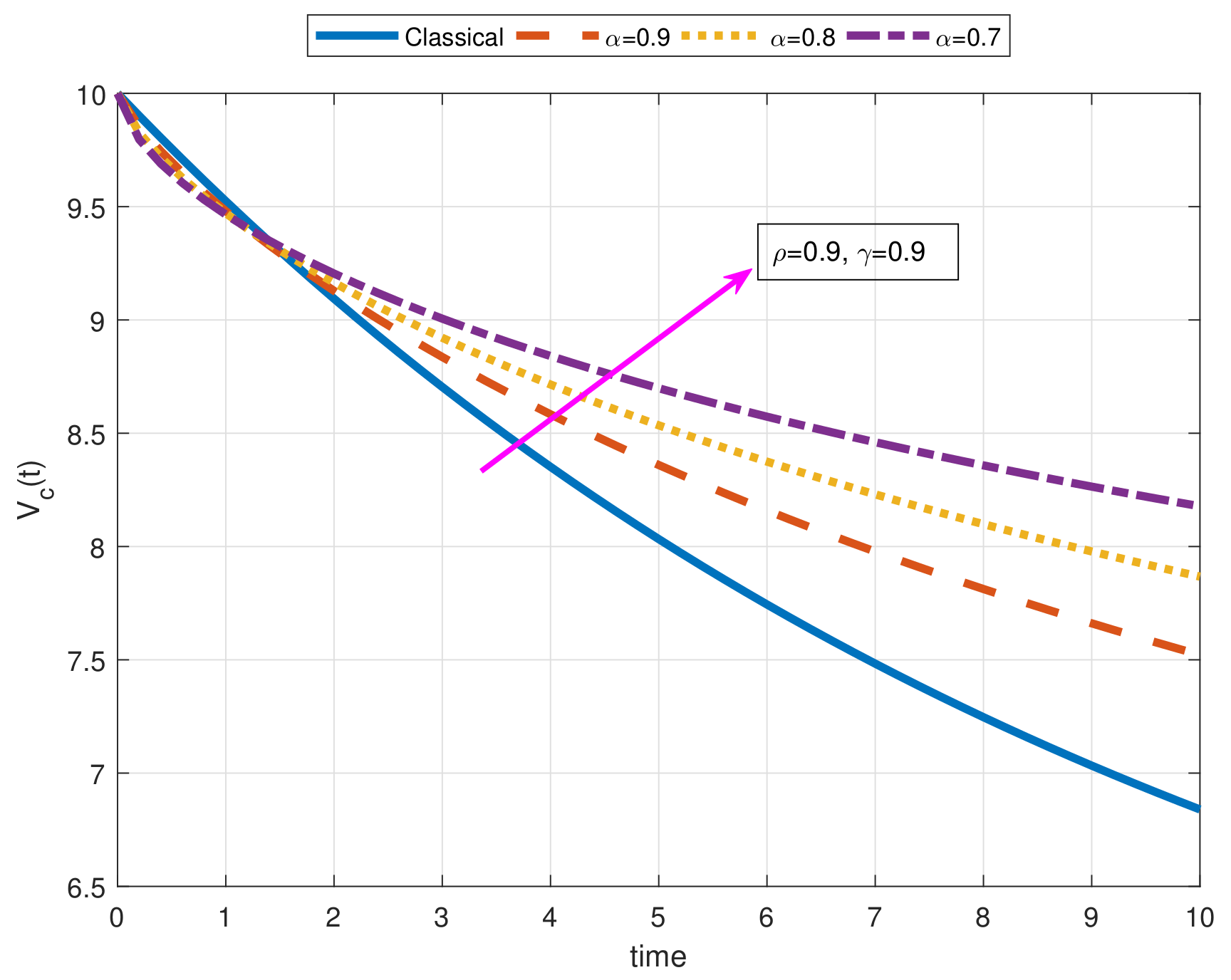
Figure 1. This figure corresponds to the function V c ( t ) with constant source for different values of α , ρ , and γ in order to show the effect of α on solution curves when R = 1 Ω , C = 10 F, e 0 = 5 V, and V c ( 0 ) = 10 .
Fractalfract 05 00009 g001
Figure 2. The figure (a) corresponds to the function V c ( t ) with constant source for different values of α , ρ , and γ in order to show the effect of α and γ , and also the figure (b) is plotted to show the effect of α and ρ when R = 1 Ω , C = 10 F, e 0 = 5 V, and V c ( 0 ) = 10 .
Fractalfract 05 00009 g002
Figure 3. This figure corresponds to the function V c ( t ) with a constant source for different values of α , ρ , and γ in order to show the effect of α on solution curves when R = 1 Ω , C = 10 F, e 0 = 5 V, and V c ( 0 ) = 0 .
Fractalfract 05 00009 g003
Figure 4. The figure (a) corresponds to the function V c ( t ) with constant source for different values of α , ρ , and γ in order to show the effect of α and γ , and also the figure (b) is plotted to show the effect of α and ρ when R = 1 Ω , C = 10 F, e 0 = 5 V, and V c ( 0 ) = 0 .
Fractalfract 05 00009 g004
Figure 5. This figure corresponds to the function V c ( t ) with an oscillatory source for different values of α , ρ , and γ in order to show the effect of α on solution curves when R = 1 Ω , C = 10 F, e 0 = 10 V, and θ = 60 Hz, V c ( 0 ) = 10 .
Fractalfract 05 00009 g005
Figure 6. The figure (a) corresponds to the function V c ( t ) with an oscillatory source for different values of α , ρ , and γ in order to show the effect of α and γ , and also the figure (b) is plotted to show the effect of α and ρ on solution curves when R = 1 Ω , C = 10 F, e 0 = 10 V, and θ = 60 Hz, V c ( 0 ) = 10 .
Fractalfract 05 00009 g006
Figure 7. This figure corresponds to the function V c ( t ) with an oscillatory source for some values of α , ρ , and γ in order to show the effect of resistance on solution curves when α = 1 , ρ = 1 , γ = 1 , C = 10 F, e 0 = 10 V, and θ = 60 Hz, V c ( 0 ) = 10 .
Fractalfract 05 00009 g007
Figure 8. This figure corresponds to the function V c ( t ) with an oscillatory source for some values of α , ρ , and γ in order to show the effect of capacitance on solution curves when α = 0.95 , ρ = 0.95 , γ = 1.5 , C = 10 F, e 0 = 10 V, and θ = 60 Hz, V c ( 0 ) = 10 .
Fractalfract 05 00009 g008
Figure 9. The figure (a) corresponds to the function I ( t ) with constant source for various values of α , ρ , and γ in order to show the effect of arbitrary parameter γ when γ = 0.7 , C = 0.5 F, L = 2.4 , e 0 = 5 V, I ( 0 ) = 0 , and similarly the figure (b) is plotted to show the effect of γ on solution curves when γ = 0.7 , C = 0.5 F, L = 2.4 , e 0 = 5 V, and I ( 0 ) = 10 .
Fractalfract 05 00009 g009
Figure 10. This graph corresponds to the solution Equation (31) containing exponential source for various values of α and ρ when γ = 0.9 , C = 0.5 F, L = 2.4 H, λ = 0.05 , e 0 = 5 V, and I ( 0 ) = 0 .
Fractalfract 05 00009 g010
Figure 11. The figure (a) corresponds to the solution Equation (31) containing exponential source for various values of α , ρ , and γ in order to see the effect of parameter L when C = 0.5 F, λ = 0.05 , e 0 = 5 V, and I ( 0 ) = 0 , and similarly the figure (b) is plotted to show the effect of L on solution curves when C = 0.5 F, λ = 0.05 , e 0 = 5 V, and I ( 0 ) = 0 .
Fractalfract 05 00009 g011
Figure 12. This graph corresponds to solution Equation (36) including oscillatory source for various values of α and ρ and γ in order to see the effect of L when C = 47 F, e 0 = 50 V, θ = 60 Hz, and I ( 0 ) = 0 .
Fractalfract 05 00009 g012
Figure 13. This plot is for the function q ( t ) with respect to the constant source for some values of α and ρ when γ = 1.2 , R = 2 Ω , L = 10 H, C = 0.1 F, e 0 = 5 V, q ( 0 ) = 10 , and M D α , ρ , γ q ( 0 ) = 0 .
Fractalfract 05 00009 g013
Figure 14. The figure (a) is for the function q ( t ) with respect to the constant source for some values of α , ρ , and γ in order to see the impact of R, and the figure (b) is plotted to see the effect of L when R = 2 Ω , L = 10 H, C = 0.1 F, e 0 = 5 V, q ( 0 ) = 10 , and M D α , ρ , γ q ( 0 ) = 0 .
Fractalfract 05 00009 g014
Figure 15. This plot is for the function q ( t ) with respect to the exponential source for some values of α and ρ when γ = 0.8 , e 0 = 5 V, L = 10 H, C = 0.1 F, R = 2 Ω , q ( 0 ) = 10 , and M D α , ρ , γ q ( 0 ) = 0 .
Fractalfract 05 00009 g015
Figure 16. This plot is for the function q ( t ) with respect to the exponential source for some values of α and ρ when γ = 1.5 , e 0 = 5 V, L = 10 H, C = 0.1 F, R = 2 Ω , q ( 0 ) = 10 , and M D α , ρ , γ q ( 0 ) = 0 .
Fractalfract 05 00009 g016
Figure 17. Comparison of the non-local M-derivative and Caputo derivative with experimental data for different values of α , ρ , and γ under the Resistance-Capacitance (RC) circuit including constant source when α = 0.9 , ρ = 1.8 , γ = 1.8 , R = 10 Ω , C = 1000 F, e 0 = 7.58 , and V c ( 0 ) = 0 .
Fractalfract 05 00009 g017
Figure 18. Comparison of the non-local M-derivative and Caputo derivative with experimental data for different values of α , ρ , and γ under the RC circuit including constant source when α = 0.7 , ρ = 1.5 , γ = 2 , R = 10 Ω , C = 1000 F, e 0 = 7.58 , and V c ( 0 ) = 0 .
Fractalfract 05 00009 g018
Figure 19. Comparison of the non-local M-derivative and Caputo derivative with experimental data for different values of α , ρ , and γ under the RC circuit including constant source when α = 0.9 , ρ = 1.8 , γ = 1.8 , R = 10 Ω , C = 1000 F, e 0 = 0 , and V c ( 0 ) = 7.58 .
Fractalfract 05 00009 g019
Figure 20. Comparison of the non-local M-derivative and Caputo derivative with experimental data for different values of α , ρ , and γ under the RC circuit including constant source when α = 0.7 , ρ = 1.5 , γ = 2 , R = 10 Ω , C = 1000 F, e 0 = 0 , and V c ( 0 ) = 7.58 .
Fractalfract 05 00009 g020
Publisher’s Note: MDPI stays neutral with regard to jurisdictional claims in published maps and institutional affiliations.