Abstract
Grooved liquid annular seals have a significant influence on the design of turbomachines. Corresponding lubrication film models need to account for the different friction behavior of the grooves compared to plain seals. However, there is a lack of reliable and validated models for this purpose. Thus, the applicability of a friction factor model is explored and a calibration method is presented. A single square groove is investigated by means of 96 steady-state RANS simulations for different operation conditions and groove geometries. The results are used to calibrate the friction model and successfully verify it in terms of the pressure drop over the groove. For validation, two full grooved seals with relatively large square grooves were investigated by experiment. The friction model was incorporated in a lubrication model and compared to the measurement data for the pressure difference and the resulting force for specified leakage and eccentricity. The model predictions for the pressure difference can be considered very good. The force predictions show significant deviation, but can be considered acceptable given the low force magnitudes and measurement uncertainty. The results offer a general validity to our friction model approach, assumptions and the calibration method.
1. Introduction
Liquid annular seals and journal bearings have a significant influence on the design of turbomachines like centrifugal pumps. Firstly, increasing power density and operational flexibility necessitate a precise rotordynamic design of a turbomachine and thus accurate knowledge of the forces acting on the rotor. The added mass, damping and stiffness of a seal or bearing influence resonance frequencies and stability. Secondly, the axial leakage flow through such an annulus is of importance for the volumetric efficiency of the pump and internal hydraulics, e.g., axial thrust balancing devices or pressure balancing ducts.
For the prediction of the rotordynamic coefficients and the leakage flow, integro-differential fluid film/lubrication models (i.e., bulk flow models) are generally used. In contrast to CFD, these models are used as fast design tools and for optimization applications. The recently developed Clearance-Averaged Pressure Model (CAPM) [1,2,3,4] is a two-dimensional lubrication model for incompressible flow in plain annular gaps covering the full parameter space (laminar and turbulent flow, superposed axial flow, low to high eccentricity). The CAPM has been validated for plain cylindrical geometries at turbulent flow [3] and at laminar flow [1].
While the behavior of these plain cylindrical geometries can be predicted reliably, this does not apply to grooved (labyrinth) or damper seals which are characterized by a profiled stator. The change in friction behavior affects both leakage and the forces on the rotor. Considering the lack of validated and reliable models, it is necessary to investigate generic grooved seals. Since a grooved seal is just a series of single grooves, the flow and friction behavior of such a single groove is investigated by means of CFD simulations in the present paper. The considered grooves can be regarded as rather large compared to the mean gap height and are of square cross-section.
The main characteristic feature of the flow in such a groove is the free turbulent shear layer which has theoretical similarity to a wall boundary layer. Thus, an empirical approach with the wall friction model of Hirs [5] is feasible and explored in the present paper. Necessary extensions due to the shear layer and a elaborate calibration method are presented to account for additional dependencies on operation conditions and the scaling with rotor eccentricity and groove geometry. The results can help the understanding of the friction behavior of grooved seals and can be easily included in lubrication models for plain annular seals like the CAPM.
Finally, the calibrated friction model for the grooves in conjunction with the CAPM is validated against experimental data for two different grooved seals by means of the pressure difference and the load bearing capacity of the seals for different flow numbers and eccentricities.
The methods and results shown in this paper are an extension of our conference paper published in the “Proceedings of the 15th European Turbomachinery Conference” [6]. In comparison to the conference paper, we extended the CFD study for model calibration from 24 to 96 cases to include varying groove geometry, added a corresponding section about geometry scaling and validated the model with experimental data.
Literature
After some earlier attempts by other researchers, Iwatsubo and Sheng [7] and Florjancic [8] were the first who derived substantial lubrication models for liquid labyrinth seals. Their models were based on a multi-control volume bulk flow approach. Later, the three control volume approach of Florjancic [8] was employed and modified by several researchers [9,10,11,12].
The model of Florjancic [8] was inspired by findings related to gas labyrinth seals in centrifugal compressors, e.g., Wyssmann et al. [13] or Scharrer [14]. The key aspects of the model are the following: The seal geometry of a singular land and groove are divided into three control volumes based on physical effects. Firstly, in the land part, the typical bulk flow approach is used. Secondly, a free shear layer exists over the groove. Thirdly, a singular vortex is assumed inside the groove.
For the circumferential direction, a so-called jet shear stress model was introduced by Wyssmann et al. [13] for the shear layer. It is based on a solution of a plane turbulent mixing layer for the profile of the mean velocity and Prandtl’s mixing length turbulence model with an empirical correlation for the mixing length. Wyssmann et al. [13] only considered the shear stress in the circumferential direction in this way and neglected the axial component. In contrast, Florjancic [8] considered both the circumferential and axial component of the mixing layer. He regarded the result of the jet shear stress model as an effective magnitude which needed to be decomposed into its corresponding vector components. For this, he used the bulk velocity components in the same manner as for the model by Hirs [5] for the wall shear stress. This approach was used by all subsequent researchers mentioned above and is an essential part of coupling the control volumes over and inside the groove for multi-control volume models.
While there have been some attempts to use and calibrate a Hirs model for damper seals, e.g., Childs and Fayolle [15], little research has been conducted for grooved seals. Thus, in the present paper, an empirical Hirs approach for a grooved seal is derived.
2. Materials and Methods
In this section, the theory and fundamentals of the present paper are described. We first introduce the model CAPM for the dynamics of the fluid film in the annular seal, and then we derive the extensions of the friction model for grooved seals. Afterwards, we present the simulations we used to calibrate the friction model, and finally, we shortly describe the test rig we used for experimental validation of our models. Definitions not mentioned in the text can be found in the nomenclature. Throughout the paper, symbols with a tilde represent dimensional quantities, and ones without a tilde represent the corresponding nondimensional quantities.
2.1. Clearance-Averaged Pressure Model
The Clearance-Averaged Pressure Model (CAPM) [1,3,4,16] is an integro-differential model and solver for incompressible flow in narrow plain annular gaps. Since the model takes into account all non-linearities including the convective inertia terms, it is valid for laminar and turbulent flow conditions as well as high eccentricity. The CAPM includes Reynold’s equation as limiting case for negligible fluid inertia as well as a 2D bulk flow model for high Reynolds numbers. Furthermore, for turbulent flow with moderate Reynolds numbers, power law ansatz functions are used as velocity profiles which can improve the convective inertia terms.
The CAPM model geometry of a plain annular gap is depicted in Figure 1. The rotor (radius , rotational speed ) can be dislocated with the eccentricity and misaligned with the tilt angle . However, in this study, we only consider parallel rotor positions, i.e., . The seal has the length and the outer radius , where is the mean gap height. The local gap height is a function of the circumferential and axial coordinate due to eccentricity and/or misalignment.
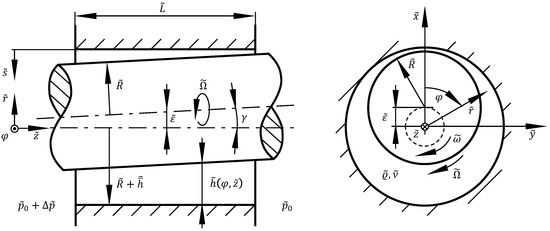
Figure 1.
Model geometry of the Clearance-Averaged Pressure Model (CAPM) for plain annular gaps.
The total axial volume flow though the annular gap due to an axial pressure difference is characterized by the mean axial velocity . The fluid enters the gap with the circumferential velocity which can vary due to preswirl. The flow is assumed to be incompressible and of Newtonian fluid (kinematic viscosity , density ). We exclude cavitation from our analysis.
To be able to calculate rotordynamic coefficients, the rotor is assumed to perform an orbital motion with rotational frequency around the bearing centerline, cf. [17]. Thus, the CAPM is based on a cylindrical coordinate system in a rotating reference frame with the same rotational speed as the orbit motion. With this, the absolute velocity can be stated with the relative velocity as
This method enables the elimination of the time dependency of the variables caused by the orbital motion of the rotor and reduces the problem to a quasi-steady state. However, in this study, we do not consider an orbit motion or rotordynamic coefficients, i.e., .
The considered control volume for the model extends over the complete gap height and infinitesimal segments in axial and circumferential directions. Due to , the pressure gradient in the direction of the gap height is negligible [18,19]. On this basis, the steady-state governing equations of the CAPM are given by Lang [16]. The nondimensional (see nomenclature) continuity equation, the circumferential and axial momentum equation for this control volume read
To close Equation system (2) to (4), ansatz functions for the velocity profiles and have to be defined so that the integrals over the gap coordinate s can be evaluated. While any ansatz functions can be used (e.g., power law profiles, cf. [16]), we use bulk velocities averaged over the gap height in the present paper. Thus, we obtain and . Furthermore, the wall shear stress terms
have to be provided. For turbulent flow, Lang used the well-known friction factor model by Hirs [5] which is common for bulk flow models, too.
The independent variables and z then are discretized in a finite differencing scheme and the system of coupled nonlinear partial differential equations is solved by means of a SIMPLEC algorithm [20]. The results are the pressure field and the velocity fields and . The solution also produces the flow number representing the leakage volume flow with prescribed pressure difference or vice versa. As the outlet boundary condition at , we only prescribe a constant pressure. At the inlet , the Lomakin effect has to be considered by means of Bernoulli’s equation with a pressure loss coefficient [1].
To obtain the resulting forces on the rotor, we make use of an additional Cartesian coordinate system which is also shown in Figure 1. The -coordinate always aligns with the direction of eccentricity. The lateral force components and are calculated by integrating the pressure over the rotor surface. The resulting force magnitude on the rotor (load capacity) is given by
2.2. Hirs’ Bulk Flow Friction Factor Model
The findings of Hirs [5] on wall friction in turbulent lubrication films laid the foundations for current bulk flow models for incompressible flow. He showed that
- the correlation of Blasius [21] for wall friction factors can be used for both bounding walls of a lubrication film, even if there is relative wall motion, with the use of effective bulk Reynolds numbers;
- the empirical parameters of the Blasius correlation only depend weakly on the type of flow (Poiseuille, Couette, superposition of both);
- the effective wall shear stress can be separated into the directional components analogously to the bulk velocity components.
In the following, the typical model equations and our extensions are presented.
The nondimensional effective wall shear stress magnitude is defined as
The shear stress is needed per wall, and in the case of a journal bearing or annular seal, the subscript represents . The bulk velocity (averaged over gap height) relative to the possibly moving walls is defined as
Typically, only the rotor wall moves in the circumferential direction so that relative axial velocities are equal to the mean absolute velocity and the stator circumferential velocity is . The rotor relative velocity is .
The Fanning friction factor is defined as
and with the local effective wall Reynolds number
we can establish a Blasius power law correlation for the friction factor
in which m and n are empirical parameters. Guiding values (converted to our definitions above) for the parameters are given by Childs [17] with and ; Lang [16] gives values of and determined by CFD for hydraulically smooth surfaces. The parameters can depend on the Reynolds number, wall roughness and—as we show below for grooved seals—on other parameters. Of course, it is possible to use wall-specific parameters and if the friction behavior is different.
Hirs assumed that the shear stress components point directly in the opposite direction of the wall relative bulk velocities, i.e., the angles between the vector components of wall shear stress and bulk velocity are the same. With the included angle between circumferential component and magnitude, the condition can be stated as
or
The nondimensional wall shear stress components read
where the sign depends on the specific wall and flow direction. If Condition (13) is met, Equations (15) and (16) are equal to
which is the common form successfully used in lubrication models for plain seals and bearings. However, as shown below, we see that Condition (13) is generally not justified for grooved seals. For this reason, we introduce an empirical correction factor for the angle,
and the shear stress components become
We find that this friction factor model can also be applied to grooved seals. The cross-section of a single groove and the control volume of interest CV is shown in Figure 2a. While the upper side is at the rotating wall as usual, the wall shear stress is yet influenced by the flow in the groove. The stator side of the control volume intersects the fluid in the groove on the height of the land wall. Here, a turbulent shear layer similar to a wall jet [22,23] is forming in the axial direction. In the circumferential direction, an asymmetric turbulent Couette flow due to the rotor movement is forming. Since free shear layers are theoretically similar to boundary layers [23], the Hirs/Blasius approach can also be suitable for modeling the Reynolds stress at the stator side. However, additional dependencies on operation conditions and groove geometry for and have to be considered, which we explore in the present paper.
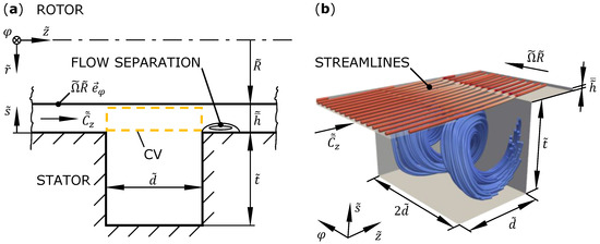
Figure 2.
(a) Model geometry of a single groove with control volume CV. (b) Computational domain with exemplary streamlines colored by velocity magnitude.
2.3. Entrance Pressure Loss after the Groove
The axial turbulent shear layer over the groove leads to entrainment, which means that the fluid outside the boundary of the jet is accelerated in the direction of the jet due to turbulent mixing. This diffusive turbulent momentum transport leads to a broadening of the velocity profile into the groove and at the same time to a general deceleration of the jet. But since the continuity condition must be fulfilled from groove inlet to outlet, the flow is accelerated again out of the groove into the gap. Hence, a flow separation with a vena contracta forms. This results in an additional Carnot entrance pressure loss after each groove of a seal.
Integration of the shear stress at the rotor wall and in the turbulent free shear layer (stator side of control volume CV in Figure 2) results in an axial pressure loss , assuming the difference in the convective terms is negligible. Thus, the total axial pressure loss from the inlet to the outlet of a single groove can be written as
For our investigations, we define a pressure loss coefficient as
An alternative definition with the magnitude of the mean velocity vector could be defined as
The corresponding pressure drop can be “smudged” over the groove to obtain an additional virtual axial shear stress
with the friction factor . This eliminates the need of Bernoulli’s equation as the interface condition between different grooves, cf. [11], and converts the corresponding pressure discontinuity into a continuous slope which is beneficial for use in bulk flow models due to their differential nature.
2.4. Eccentricity and Geometry Scaling
Due to the eccentricity and the rotor tilt , the gap height h and the velocity components and become fields dependent on the coordinates and z. The friction model has to account for the eccentricity scaling and in extension for the groove geometry scaling. Typically, fluid friction scales better with local flow variables in contrast to global parameters. This is also represented by Hirs’ model, where the wall Reynolds number , Equation (12), and the calculation of the shear stress components, Equations (17) and (18), are accomplished by local variables.
Thus, we assume that the scaling with eccentricity of the friction on the rotor wall above a groove and the fluid friction due to Reynolds stress in the shear layer on the stator side of the groove is similar to the usual Hirs model. For this, we need to define an additional local flow number
as the ratio of the local mean absolute velocity components. The factor is added so that for the concentric case, since, in this case, by definition and . Analogously, we define the local groove parameters
and
With regard to our results presented below, we find the following dependencies on the operation conditions as power laws:
Finally, we assume approximately linear dependencies of the power law parameters on the square groove geometry (), closing our theory:
The 22 coefficients and with to 11 are assumed to be constant empirical model parameters which need to be calibrated in the specific parameter range of interest.
2.5. Simulations
A number of 96 three-dimensional steady-state RANS simulations for incompressible flow of Newtonian fluid and constant fluid material properties are carried out in OpenFOAM v2006 to analyze the flow and calibrate the empirical model parameters. The plane computational domain is shown in Figure 2b and represents a single rectangular groove of a concentric annular seal neglecting the curvature. This simplification can be justified by the small relative gap height of . The groove is assumed to have a square cross-section with . A purely computational depth is introduced to capture three-dimensional flow effects. The gap before and after the groove have each a length of , which assures fully developed velocity profiles at the beginning of the groove.
Due to the concentric/plane geometry and the fully developed flow, by definition, and . The simulations do not offer direct insight into the effects of eccentricity. However, the simulations seem to be suited to calibrate the model which takes care of the eccentricity and groove geometry scaling. This can be accomplished because the local variables are equal to the global variables in the concentric case, i.e., , and .
A Low-Reynolds approach with and the k--SST turbulence model are used in the simulations. Depending on the effective Reynolds number, the used structured grids have around to cells for a grid-independent solution. In the circumferential direction, a periodicity boundary condition is used. At the inlet, a mean axial velocity corresponding to the flow number and a mean circumferential velocity of is prescribed. The rotor wall translates in a circumferential direction with velocity .
The varied parameters are (i.) the Reynolds number
governing the circumferential velocity of the rotor wall, (ii.) the flow number
governing the axial volume flow and (iii.) the square groove geometry width
The corresponding combinations result in 96 simulation cases.
The simulations are used to determine the surface averaged wall shear stress components on the rotor and (cf. control volume CV in Figure 2), the surface averaged Reynolds stress components above the groove and as well as the total axial pressure drop over the groove (excluding the inlet and outlet channels) with a Bagley method [1].
2.6. Annular Seal and Journal Bearing Test Rig
For experimental validation, we used our test rig for annular seals and journal bearings [3,24,25,26]. A schematic is shown in Figure 3, which we describe here shortly. In the center, the annular gap is located. The seal geometry can be varied by exchangeable rotor sleeves and stator rings. The rotor is driven by a motor with variable speed and supported by two active magnetic bearings (AMB). The magnetic bearings allow for precise positioning and arbitrary lateral movements of the rotor, i.e., adjustment of eccentricity , tilt angle and orbit frequency . Furthermore, the magnets are equipped with Hall sensors to measure the magnetic flux density and calculate the resulting bearing force and thus the hydrodynamic forces and exerted on the rotor by the fluid film in the annular gap. The position of the rotor is measured in the gap with eddy-current distance sensors integrated in the stator ring.
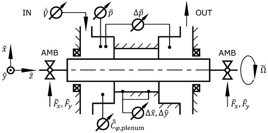
Figure 3.
Schematic depiction of the annular seal and journal bearing test rig.
The inlet chamber is simplified in the schematic for clarity. In fact, it consists of two connected chambers from which the first leads to the seal entrance and the second to a by-pass outlet. The water is injected tangentially to the first chamber through twelve nozzles around the circumference. With a valve the part of the volume flow exiting through the by-pass can be adjusted. By means of this method, the mean circumferential velocity of the fluid in the inlet chamber as well as the leakage volume flow through the seal can be adjusted. The mean circumferential velocity is measured with an angled Pitot tube.
Furthermore, the fluid temperature, the volume flow through the seal represented by the flow number , the by-pass volume flow, the static pressure in the inlet chamber and the axial pressure difference over the seal are measured. Cavitation is prevented by applying a static system pressure.
3. Results
In this section, we first present the results of the friction factor model for the groove geometry as representative case. Then, we compare the four different groove geometries and present the linear regressions for the empirical model parameters. Finally, we present a comparison of measurement data and model prediction for validation.
3.1. Calibration of the Friction Factor Model for a Single Groove Geometry
In this section, we investigate the exemplary case with varying operation conditions. Qualitatively, the the method and results are the same for the other three groove geometries.
The wall shear and Reynolds stress at the rotor and stator side of the control volume CV (Figure 2) are evaluated from the simulations and averaged over the surfaces. The friction factors Equation (10) and the fitted Blasius correlations Equation (12) over the effective wall Reynolds numbers are shown in the double logarithmic diagram of Figure 4 (log is the decadic logarithm). On the rotor side, three groups of the data points for the three global Reynolds numbers can be seen, but a single fit is sufficient. On the stator side, a clear dependence on the flow number can be seen. Thus, a fit for each flow number is made. The powers vary only very slightly so that the average is used for all lines in Figure 4b.
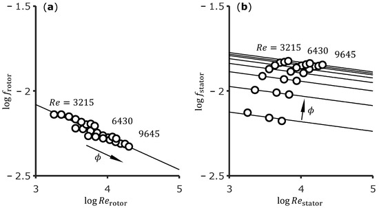
Figure 4.
Effective friction factors on (a) rotor and (b) stator with power law fits.
The stator coefficient over the flow number is shown in Figure 5a. The curve suggests an asymptotic behavior for higher values of . This seems physically reasonable since both the friction factor and the wall Reynolds number are dominated by the axial component. The function can be approximated well with a power law. It has to be mentioned that the fit fails for , but this is an unrealistic operation condition for annular seals. However, for this case, a polynomial could be used.
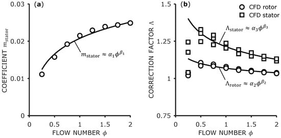
Figure 5.
(a) Flow number dependence of the stator friction factor coefficient. (b) Angle correction factors for rotor and stator.
As expected, the values , , and identified for the friction over a groove differ significantly from the values given by Childs [17] and Lang [16] for plain seals mentioned above. This results in a slightly lower friction factor at the rotor compared with a plain gap. However, the stator friction factor for the groove is significantly higher. This difference to the plain seal increases with higher flow numbers and higher wall Reynolds numbers.
As previously described, angle correction Equation (19) has to be considered. The results for both rotor and stator are shown in Figure 5b. A slight dependence on the flow number is recognizable. Beginning with , this dependence can also be described with a power law, while the values for show differing behavior. Thus, these values are excluded from the fitting curves shown in the figure, which might add some model error at low flow numbers. Furthermore, the dependence on the Reynolds number can be neglected.
The shear stress components in circumferential and axial direction on rotor and stator are shown in Figure 6. The circular markers represent the CFD results and the square markers represent the results of the extended Hirs model with all the fits presented above. It can be seen that the empirical model can represent the actual shear stress very well in almost all cases. For the rotor side, some slight deviation can be seen for the axial component. The cases for a low Reynolds number and a high flow number produce the highest magnitude in shear stress. Here, the fit shown in Figure 4 results in a noticeable difference.
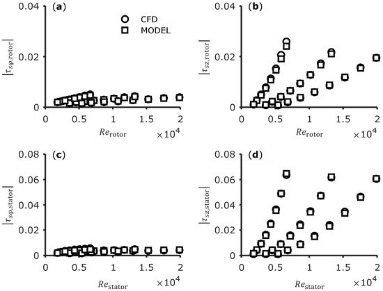
Figure 6.
(a,b) Circumferential and axial shear stress components on the rotor side. (c,d) The same on the stator side.
Besides that, it has to be mentioned that excluding the outliers for in the angle correction fit does not result in significant model error since the absolute values of the shear stress components are low. In contrast, the relative model deviation averaged over all cases can be significantly reduced by using the velocity correction, especially on the stator (groove) side and in circumferential direction.
Finally, the virtual friction factor due to the entrance pressure loss after the groove has to considered. The friction factor over the flow number is shown in Figure 7a. Similar to the other curves, a dependence on the flow number and no significant dependence on the Reynolds number is seen. The data points can be approximated well with a power law, too. In Figure 7b, the total axial pressure loss over the groove is shown. Again, the circular markers show the data from the CFD simulations while the square markers show the model results calculated with the fitting curves and Equation (22). The fraction of the entrance pressure loss relative to the total pressure loss is between and for all 24 cases, decreasing with increasing flow number.
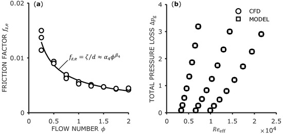
Figure 7.
(a) Flow number dependence of the virtual friction factor due to the entrance pressure loss. (b) Total axial pressure loss over the groove.
This verification shows that the calibrated model laid out above can make accurate predictions for the pressure loss in all cases compared to CFD. It has to be mentioned that the axial pressure loss is only a verification for the entrance pressure loss and the axial shear stress components. However, the same prediction accuracy for the shear stress in circumferential direction can be expected regarding Figure 6.
3.2. Geometry Scaling
While the results presented above are all taken from the case , the qualitatively same behavior is shown by the other geometries, . It is found that all coefficients of the power laws are dependent on the groove geometry to some extent.
Exemplary plots of the coefficients and over the groove geometry are shown in Figure 8. The markers represent the power law coefficients determined from the 96 simulation cases and the lines are determined by linear regression. The two specific coefficients are chosen because they represent the best and worst fit in terms of root-mean-square error (RMSE) weighted with the mean of the data nodes. The RMSE for all eleven regressions is listed in Table 1. While the two coefficients and show a certain (still acceptable) deviation from a linear function, the other nine coefficients qualitatively are approximated very well by a linear regression. This might indicate that for the two rotor coefficients, another function would be better suited. Nonetheless, we would not infer a nonlinear function from the limited data points and accept the fit deviation. The result values of the 22 regression parameters are also listed in Table 1.
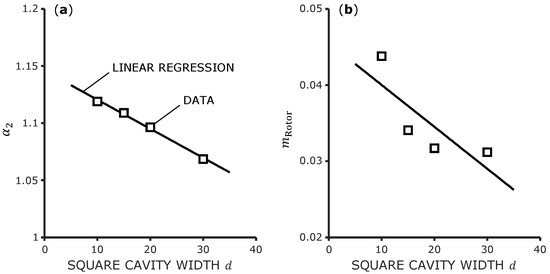
Figure 8.
(a) Best linear regression in terms of RMSE. (b) Worst linear regression in terms of RMSE.

Table 1.
Values of the empirical model parameters and RMSE of the linear regression weighted with the mean of the data nodes. The RMSE values are divided by .
3.3. Theory vs. Experiment
For validation, two full grooved seals are investigated. The periodic seal geometry is shown schematically in Figure 9. The total seal length can generally be calculated with
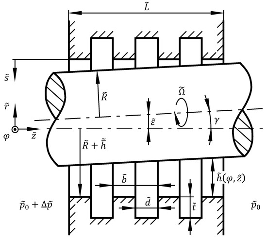
Figure 9.
Model of the full periodically grooved seal.
Also, the ratio of the seal surface covered by grooves to the total cylinder surface is calculated with
Seal 1 has a number of square grooves of dimensions . The profile width is , i.e., the land has double the width compared to the groove. Seal 1 has a length of and a surface ratio of . Seal 2 has square grooves of dimensions . The profile width is , which means that the groove and land widths are equal. The length is and the surface ratio is . For both seals, the mean relative gap height is .
The seals are investigated experimentally by means of the test rig described in Section 2.6. The global Reynolds number is constant, . The flow number and the eccentricity are varied. The inlet circumferential velocity is constant with for all cases. The measurement uncertainty (95% CI) for these parameters is , , , and .
The model predictions are computed with the CAPM in conjunction with the new friction model described and calibrated above. It is possible to discretize the whole seal and to designate the grooves and lands as separate regions where the specific friction models are applied locally. On the lands, the basic Hirs model is used, while on the grooves, the extended model is applied. It is also possible to compute a surface averaged value of an effective mean shear stress over a profile element which does not rely on the designated land and seal regions.
While the treatment of the shear stress is unproblematic and robust, it turns out that a second physical constraint has to be applied. Since the grooves are rather large, the pressure is not only constant in the cross-section. It is also constant in the whole groove over the circumference, i.e., in the grooves. This condition can be easily enforced in the solver but leads to a discontinuity in the pressure field at each transition between land and groove for eccentric cases. This discontinuity leads to divergence of the iterative solution algorithm in its current form.
Because of this problem, we use a separated and sequential calculation process. Each land and each groove is discretized on its own and solved separately, which is similar to a two-control-volume model. At the first land inlet, the typical pressure loss boundary condition is applied. Then, the pressure and velocity field boundary conditions are propagated from each outlet to the next inlet until the end of the seal. The individual pressure differences and force components for each segment can be simply summed up over all lands and grooves to obtain the wanted total values for the complete seal. However, this method is only possible for a fixed flow number .
The results for Seal 1 are shown in Figure 10. In Figure 10a, the pressure difference over the eccentricity is shown for different flow numbers . The markers represent the measurement values with standard uncertainty (95% CI) as error bars. The lines represent the CAPM predictions. It can be seen that decreases slightly with increasing eccentricity and increases strongly with increasing flow number. The CAPM over-predicts the pressure difference slightly in in all cases, but it can be considered to be in very good agreement with the experiment. Additionally, it predicts the scaling with and qualitatively very well.
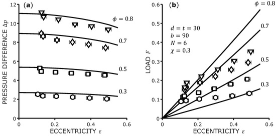
Figure 10.
Validation data for Seal 1. (a) Pressure difference over eccentricity. (b) Load over eccentricity.
In Figure 10b, the load F (resulting force magnitude) on the rotor is shown, again over the eccentricity and for the same flow numbers . Due to the fact that the large grooves do not offer any support to the rotor, the magnitude of the load can be considered very small. For the interval , the load shows a linear dependence on , which is typical for plain seals and can be expected at a low surface ratio . However, the measured values do not extrapolate to the theoretically correct value at due to the uncertainty in the other operation conditions. It seems that a value of is the limit of the general resolution of load measurement of the test rig. While the load predictions of the CAPM can be considered acceptable for the lower flow numbers, the model over-predicts the load for and at higher eccentricity. The slope generally seems to be slightly excessively steep for the investigated cases.
In Figure 11, the same diagrams are shown for Seal 2. For the lower flow numbers, the pressure difference is slightly over-predicted again. However, for , the measured data are slightly higher than in the model predictions. Due to the higher surface ratio , the load bearing capacity of Seal 2 is even lower than that of Seal 1. The measured load is mostly above the model curves while the slope of the model seems to be too steep again. The model predictions indicate a slightly nonlinear progression of the load with increasing eccentricity. Again, we consider the agreement of the model for very good and for F acceptable.
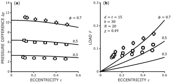
Figure 11.
Validation data for Seal 2. (a) Pressure difference over eccentricity. (b) Load over eccentricity.
4. Conclusions
The flow in a single groove of a concentric grooved liquid annular seal was analyzed by means of 96 CFD simulations in the range of Reynolds number , flow number and groove width . The friction behavior was analyzed in the context of two-dimensional fluid film/lubrication models for annular seals. It was found that the well-known Hirs [5] friction factor model is applicable but needs elaborate calibration due to additional dependencies on operation conditions and groove geometry. Furthermore, the entrance pressure loss at the transition from the groove to the gap was evaluated.
In the classical Hirs model, it is assumed that the ratio of the shear stress components is equal to the ratio of the wall relative bulk velocity components. In the present paper, it was shown that this assumption is not justified in the case of grooved seals. Thus, an empirical angle correction function was introduced. This hints at the fact that the gap bulk velocities are not ideal scaling velocities for the friction in the turbulent shear layer. Nonetheless, the gap bulk velocities are the only reasonable choice for a general lubrication model like the CAPM.
With all the considerations mentioned above, the model was verified with the CFD simulations and performed very well in all cases predicting the total axial pressure drop over the groove. For validation, two different full grooved seals with 6 and 20 square grooves were investigated by experiment. Measurements were taken for the axial pressure difference over the seal and the load bearing capacity at specified leakage volume flows and eccentric rotor positions. The experimental data were compared to model predictions of the fluid film model CAPM in conjunction with the calibrated Hirs friction factor model for the grooves.
Even though the model slightly over-predicted the pressure difference over the seal for most cases, the agreement with the experiment can be considered very good. The measured values for the load were generally very small due to the large grooves which did not provide any support to the rotor. The model predictions of the load tended to be generally too high and increasing too much with eccentricity. While the prediction accuracy of the load certainly needs to be improved, it can be considered acceptable in consideration of the very low absolute values and measurement uncertainty.
However, the results certainly offer a general validity to our approach of the friction model, our assumptions as well as the calibration method we developed. In terms of complexity, four empirical constants are needed for a plain seal with different friction behavior of rotor and stator. For a grooved seal, 22 constant empirical model parameters are needed. For further improvement of the model, the transition between groove and land and vice versa for a full three-dimensional eccentric groove or complete seal could be analyzed by means of CFD.
Author Contributions
Conceptualization, methodology, software, validation, writing, visualization: R.M.R. Methodology, resources, supervision: P.F.P. All authors have read and agreed to the published version of the manuscript.
Funding
This research was funded by the German Federal Ministry for Economic Affairs and Energy (BMWi) due to an enactment of the German Bundestag under grant number 03EE5036B.
Data Availability Statement
Data are contained within the article. Additional data are available on request from the corresponding author.
Acknowledgments
The authors would like to thank our colleague M. M. G. Kuhr (Chair of Fluid Systems, Technische Universität Darmstadt) who conducted the experiments and provided the measurement data as well as the uncertainty data. The authors would also like to thank our industrial research project partner S. R. Lang (KSB SE & Co. KGaA) for the support and helpful discussions.
Conflicts of Interest
The authors declare no conflict of interest.
Nomenclature
The following abbreviations are used in this manuscript:
| flow number | |
| Reynolds number | |
| relative mean gap height | |
| relative eccentricity | |
| nondimensional seal length | |
| orbit frequency ratio | |
| nondimensional local gap height | |
| nondimensional channel coordinate | |
| nondimensional axial coordinate | |
| nondimensional axial velocity component | |
| nondimensional circumferential velocity component | |
| nondimensional pressure | |
| nondimensional force | |
| nondimensional groove width | |
| nondimensional groove height | |
| nondimensional periodic groove profile width |
References
- Robrecht, R.M.; Pelz, P.F. The Lomakin effect at laminar flow in journal bearings—Modeling and simulation. Tribol. Int. 2022, 175, 107792. [Google Scholar] [CrossRef]
- Robrecht, R.M.; Kuhr, M.M.G.; Pelz, P.F. CAPM vs. Bulk Flow—Reliable and efficient prediction of forces and leakage for annular gaps in pumps. In Proceedings of the Pump Users International Forum 2019, Wiesbaden, Germany, 24–25 September 2019. [Google Scholar]
- Kuhr, M.M.G.; Lang, S.R.; Pelz, P.F. Static Force Characteristic of Annular Gaps—Experimental and Simulation Results. J. Tribol. 2022, 144, 111804. [Google Scholar] [CrossRef]
- Kuhr, M.M.G.; Nordmann, R.; Pelz, P.F. Dynamic force and moment characteristics of annular gaps—Simulation results and evaluation of the relevance of the tilt and moment coefficients. J. Tribol. 2022, 145, 011801. [Google Scholar] [CrossRef]
- Hirs, G.G. A Bulk-Flow Theory for Turbulence in Lubricant Films. J. Lubr. Technol. 1973, 95, 137. [Google Scholar] [CrossRef]
- Robrecht, R.M.; Pelz, P.F. Friction Model for Grooved Annular Seals for Use in Fast and Reliable Design Tools. In Proceedings of the 15th European Turbomachinery Conference, Paper No. ETC2023-208, Budapest, Hungary, 24–28 April 2023; Available online: https://www.euroturbo.eu/publications/conference-proceedings-repository/ (accessed on 24 September 2023).
- Iwatsubo, T.; Sheng, B. Evaluation of Dynamic Characteristics Parallel Grooved Annular Seals by Theory and Experiment. In Proceedings of the 3rd International Conference on Rotordynamics, Lyon, France, 10–12 September 1990; Ed. du Centre National de la Recherche Scientifique: Paris, France, 1990; pp. 313–318. [Google Scholar]
- Florjancic, S. Annular Seals of High Energy Centrifugal Pumps: A New Theory and Full Scale Measurement of Rotordynamic Coefficients and Hydraulic Friction Factors. Ph.D. Thesis, ETH Zürich, Zürich, Switzerland, 1990. [Google Scholar] [CrossRef]
- Marquette, O.R.; Childs, D.W. An Extended Three-Control-Volume Theory for Circumferentially-Grooved Liquid Seals. J. Tribol. 1996, 118, 276–285. [Google Scholar] [CrossRef]
- Ha, T.W.; Lee, A.S. A rotordynamic analysis of circumferentially-grooved pump seals based on a three-control-volume theory. KSME Int. J. 2000, 14, 261–271. [Google Scholar] [CrossRef]
- Arghir, M.; Frene, J. A Bulk-Flow Analysis of Static and Dynamic Characteristics of Eccentric Circumferentially-Grooved Liquid Annular Seals. J. Tribol. 2004, 126, 316–325. [Google Scholar] [CrossRef]
- Zhang, X.; Yin, M.; Sun, H. Establishment and solution of governing equation for plana-grooved liquid seals based on three-control-volume theory. Ind. Lubr. Tribol. 2019, 72, 257–266. [Google Scholar] [CrossRef]
- Wyssmann, H.R.; Pham, T.C.; Jenny, R.J. Prediction of Stiffness and Damping Coefficients for Centrifugal Compressor Labyrinth Seals. J. Eng. Gas Turbines Power 1984, 106, 920–926. [Google Scholar] [CrossRef]
- Scharrer, J.K. A Comparison of Experimental and Theoretical Results for Labyrinth Gas Seals. Ph.D. Thesis, Texas A&M University, College Station, TX, USA, 1987. [Google Scholar]
- Childs, D.W.; Fayolle, P. Test Results for Liquid “Damper” Seals Using a Round-Hole Roughness Pattern for the Stators. J. Tribol. 1999, 121, 42–49. [Google Scholar] [CrossRef]
- Lang, S. Effiziente Berechnung von Gleitlagern und Dichtspalten in Turbomaschinen: Dissertation, Technische Universität Darmstadt, 2017; Shaker Verlag: Aachen, Germany, 2018. [Google Scholar]
- Childs, D.W. Turbomachinery Rotordynamics: Phenomena, Modeling, and Analysis; Wiley: New York, NY, USA, 1993. [Google Scholar]
- Spurk, J.; Aksel, N. Fluid Mechanics, 2nd ed.; Springer: Berlin/Heidelberg, Germany, 2008. [Google Scholar] [CrossRef]
- Szeri, A.Z. Fluid Film Lubrication: Theory and Design; Cambridge University Press: Cambridge, UK, 2005. [Google Scholar]
- van Doormaal, J.P.; Raithby, G.D. Enhancements of the SIMPLE method for predicting incompressible fluid flows. Numer. Heat Transf. 1984, 7, 147–163. [Google Scholar] [CrossRef]
- Blasius, H. Das Aehnlichkeitsgesetz bei Reibungsvorgängen in Flüssigkeiten. In Mitteilungen über Forschungsarbeiten auf dem Gebiete des Ingenieurwesens; Springer: Berlin/Heidelberg, Germany, 1913; pp. 1–41. [Google Scholar] [CrossRef]
- Glauert, M.B. The wall jet. J. Fluid Mech. 1956, 1, 625. [Google Scholar] [CrossRef]
- Schlichting, H.; Gersten, K. Boundary-Layer Theory, 9th ed.; Springer: Berlin/Heidelberg, Germany, 2017. [Google Scholar]
- Kuhr, M.M.G. Identification of the dynamic force and moment characteristics of annular gaps using linear independent rotor whirling motions. Mech. Syst. Signal Process. 2023, 187, 109936. [Google Scholar] [CrossRef]
- Kuhr, M.M.G. Dynamische Eigenschaften Axial Durchströmter Ringspalte; Shaker Verlag: Darmstadt, Germany, 2022. [Google Scholar] [CrossRef]
- Kuhr, M.M.G.; Robrecht, R.M.; Pelz, P.F. Measuring and simulation of fluid forces in annular gaps—Generic experiments covering the relevant parameter range for turbulent and laminar flow in pumps. In Proceedings of the Pump Users International Forum 2019, Wiesbaden, Germany, 24–25 September 2019. [Google Scholar]
Disclaimer/Publisher’s Note: The statements, opinions and data contained in all publications are solely those of the individual author(s) and contributor(s) and not of MDPI and/or the editor(s). MDPI and/or the editor(s) disclaim responsibility for any injury to people or property resulting from any ideas, methods, instructions or products referred to in the content. |
© 2023 by the authors. Licensee MDPI, Basel, Switzerland. This article is an open access article distributed under the terms and conditions of the Creative Commons Attribution (CC BY-NC-ND) license (https://creativecommons.org/licenses/by-nc-nd/4.0/).