Article

Rotor Cascade Assessment at Off-Design Condition: An Aerodynamic Investigation on Platform Cooling †

Department of Engineering and Applied Sciences, Università degli Studi di Bergamo, 24044 Dalmine, Italy
*
Author to whom correspondence should be addressed.
This manuscript is an extended version of the ETC2023-131 meeting paper published in the Proceeding of the 15th European Turbomachinery Conference, Budapest, Hungary, 24–28 April 2023.
Int. J. Turbomach. Propuls. Power 2023, 8(3), 23; https://doi.org/10.3390/ijtpp8030023
Submission received: 5 June 2023 / Revised: 10 July 2023 / Accepted: 21 July 2023 / Published: 22 July 2023

Abstract

:
Off-design condition of a rotor blade cascade with and without platform cooling was experimentally investigated. The ability of the gas turbine to operate down to 50% to 20% of its nominal intake air flow rate has an important consequence in the change in the inlet incidence angle, which varied from nominal to −20°. Platform cooling through an upstream slot simulating the stator-to-rotor interface gap was considered. The impact of rotation on purge flow injection was simulated by installing fins inside the slot to give the coolant flow a tangential direction. Aerodynamic measurements to quantify the cascade aerodynamic loss and secondary flow structures were performed at Ma2is = 0.55, varying the coolant to main flow mass flow ratio (MFR%) and the incidence angle. The results show that losses strongly increase with MFR. A negative incidence allows a reduction in the overall loss even when coolant is injected with a high MFR. The more negative the incidence, the greater the loss reduction.

1. Introduction

Recent trends in power generation aim to reduce the environmental impact of anthropic activities since concerns about the irreversible consequences of global warming have grown over the past few years. The reduction in energy-related CO2 emissions to limit climate change is at the heart of the energy transition scenario [1]. The competitiveness of renewable energies vs. fossil fuels has been increasing, especially concerning electricity generation. Renewable primary energy (excluding hydro) increased by around 5.1 EJ in 2021 over the world, corresponding to an annual growth rate of 15%, stronger than the previous year’s 9% [2]. The contribution of renewable energies is expected to increase further in the upcoming decade. In the short term, gas turbine engines will be the partner of renewable energies and will play a key role in the global energy sector’s transformation from fossil-fuel-based to carbon-neutral energy sources. Gas turbines can be used to balance the energy fluctuations of renewables in the grid, as well as provide immediate emission reductions using carbon-neutral fuels like ammonia, hydrogen, or bio-jet fuel.
In order to remain competitive in the market, new-generation turbines must be designed to increase and decrease power rapidly, start up and shut down promptly, and tolerate output reductions while complying with emission regulations. Fast start-up and shutdown, with frequent load adjustments down to reduced minimum load, lead engines to operate under more critical thermo-mechanical conditions with metal distortions, which may heavily impact the fluid dynamics of the secondary air system (SAS) and, consequently, the whole engine.
A better understanding of aero-thermo-mechanical interactions and more accurate predictions of aerodynamics, heat transfer, and cooling flows in variable load operating conditions are decisive to modern engine designs. Although transient regimes might represent a significant portion of the working time of industrial gas turbines in the next coming energy production scenario, the knowledge of the behavior in reduced minimum load conditions of typical SAS components is currently limited. This is all the more true for their interactions with the main flow path in view of the deformations of stator/rotor parts. Purge air, bled from the latter stages of the compressor, is introduced into the turbine wheel space at a low radius before exiting through the rim seal at the periphery of the discs, immediately upstream of the blade endwall. Labyrinth seals are used as contactless solutions to limit as much as possible the leakage between the stationary and rotating components and to control the cooling air supply to the elements lying in the hot gas path [3]. Many studies document the performance of labyrinth seals, mostly reporting the discharge coefficient as a function of pressure ratio data [4,5], from which simple 1D design correlations can be argued. The flow through labyrinth seals has been shown to be highly sensitive to geometric variations due to changes in rotational speed, and the discharge coefficient varies significantly when the seal clearance is changed by only 2% [6,7]. Off-design flow conditions due to large variations in the clearance must be considered for further improvement of the SAS system and, consequently, of the whole engine performance.
The sealing flow emerging from the stator to the rotor interface gap interacts with the main flow, influencing both the aerodynamic and thermal performance of the rotor cascade. An exhaustive review of the available literature on this topic can be found in [8]. Loss for the blade row increases with the purge flow rate (see, for example, [9]) due to the strengthening of the horseshoe vortex-pressure side leg, which entraps most of the purge air. The increased thermal load on the first rotor has prompted designers to utilize this purge flow not only for sealing purposes but also for cooling. Typically, a ratio of purge mass flow to main flow in the range of 0.7–1.0% is sufficient to effectively seal the disk cavity from the ingress of hot gases, but larger mass fractions may be required for cooling. Indeed, raising the coolant-to-mainstream mass flow rate (MFR) has a positive effect on platform cooling (see, for example, [10]). To fully capture all flow and heat transfer phenomena related to purge to main flow interaction across the rotor, investigations on rotating rigs ([11] among others) and stationary blade cascades (e.g., [12]) have been performed over the years. Only a few researchers investigated the impact of variable rotational speed [13] and of slot dimension and shape variation (e.g., [14,15,16,17,18,19]). To the author’s knowledge, the impact of mainstream incidence variation has never been investigated before.
Turbine operating conditions can change due to a different load requirements but also due to different ambient conditions. Whatever the motivation, a reduced mass flow at fixed rotational speed translates into a negative incidence to the first rotor blade cascade for a subsonic flow condition, resulting in a reduction in secondary flows and related losses [20]. But, incidence along the blade span can significantly vary, due to the complex flow coming from the stator, resulting from the interaction between swirling combustion gases, coolant flow emerging from the combustor to stator interface gap, and stator secondary flows [21,22,23]. All these make the flow pattern interacting with the sealing flow emerging from the stator to rotor interface gap highly complicated, impacting its sealing and cooling capabilities. Lastly, reducing the operability of the turbine to the minimum load could result in a mismatch between what the compressor can deliver to the SAS and what the turbine requires for sealing, potentially compromising the safe operation of the whole engine.
This study experimentally investigates the aerodynamic behavior of a rotor blade cascade with platform cooling through an upstream slot under different incidence angles from nominal to −20°, representing possible off-design flow conditions down to the minimum load. For discrete values of this parameter, the coolant to mainstream mass flow rate MFR was varied at fixed density ratio DR = 1.0, inlet turbulence intensity level Tu1 = 7.5%, and downstream Mach number Ma2is = 0.55. The decision to keep the main flow rate at a fixed level was motivated by the desire to isolate the effect of incidence. Indeed, varying the main flow rate would have resulted in a combined change in Reynolds number Re2is and Mach number, making it difficult to identify the different contributions. On the other hand, the presented results constitute a starting point of a wider investigation whose aim is to assess the impact of off-design conditions on both aerodynamic and heat transfer behavior of a rotor blade cascade, also considering gap geometrical modifications. This manuscript is an extended version of the ETC2023-131 meeting paper, published in the Proceedings of the 15th European Turbomachinery Conference, Budapest, Hungary, 24–28 April 2023 [24].

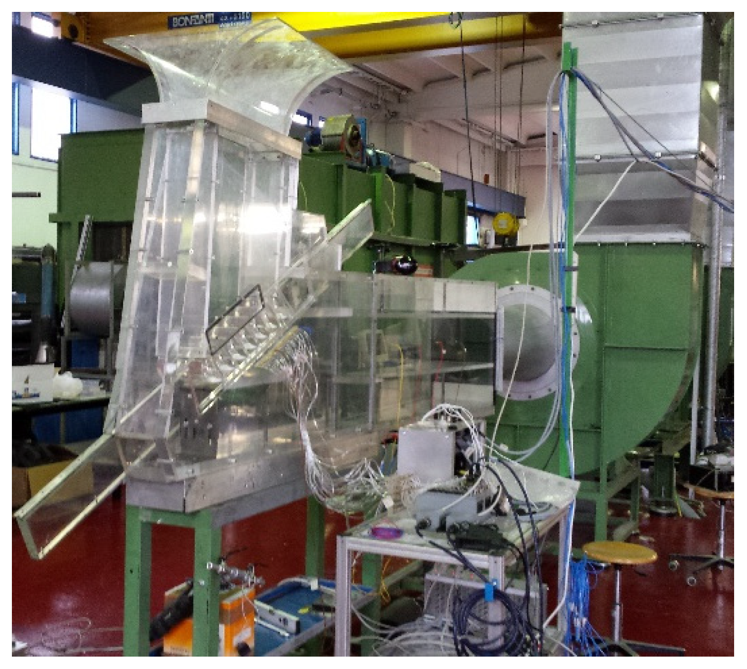
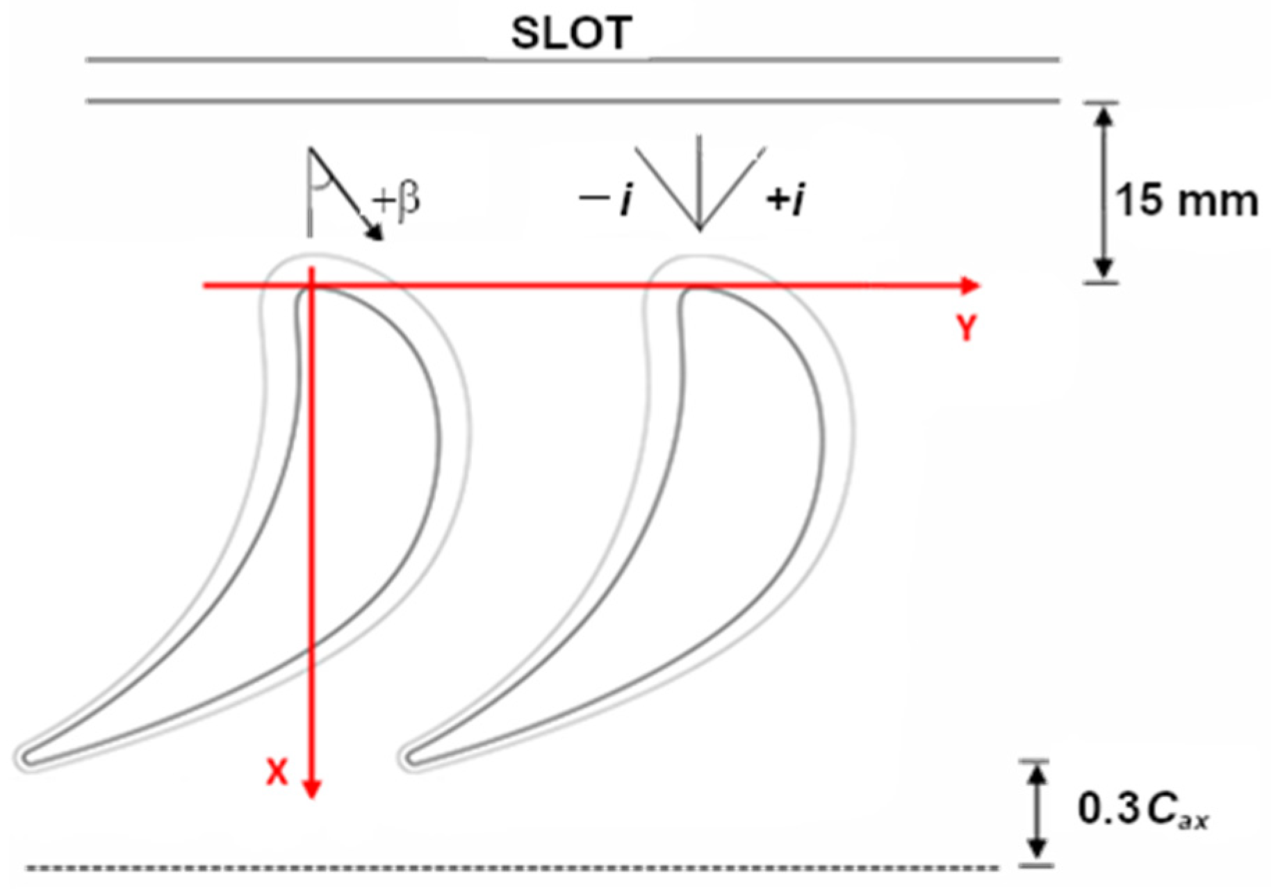
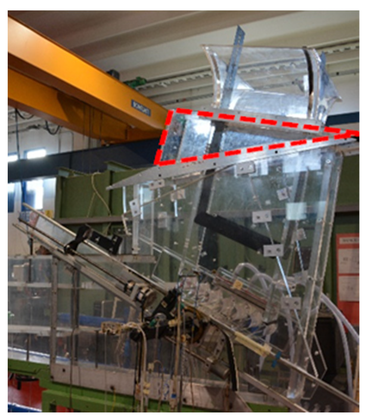
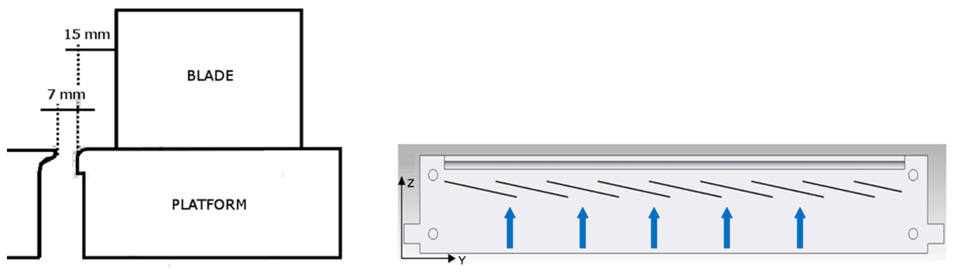
2. Experimental Setup

The experimental campaign was carried out at the continuous running, suction-type wind tunnel for rotor blade cascades shown in Figure 1. This facility and the cascade model (Figure 2) were described in-depth in [25], even if some upgrades were implemented, mostly on the fan section, allowing for a much higher exit Mach number to be reached. The wind tunnel test section hosts a 7-blade cascade typical of first-stage high-pressure turbines: the cascade is characterized by a pitch-to-chord ratio s/C of 0.637 and an aspect ratio H/C of 1.24 (Table 1). The profile of the cylindrical airfoil (Figure 2) replicates the hub section of an industrial first rotor airfoil. Similarly, the blade-to-hub junction is made through a 3D fillet, replicating the real engine design.
Tests were carried out at a fixed inlet Mach number Ma1 = 0.24, roughly corresponding to a downstream isentropic Mach number Ma2is = 0.55, varying the inlet flow angle from 0° incidence down to −20° incidence, with a regular step of 10°. In order to obtain these discrete incidence variations (−20°, −10°, 0°), the wind tunnel inlet section was re-designed. Figure 3 shows the picture of the lowest tested incidence setup (i = −20°).
The wind tunnel was operated in steady state conditions, artificially increasing the free stream turbulence intensity. This was achieved by installing a grid made of cylindrical rods in the entrance section. The turbulence decay was similar to those shown in [25], providing a Tu1 = 7.5% at the leading edge plane, as verified by a two-component Laser Doppler Velocimeter.
Inlet flow condition was monitored 1.0 Cax upstream of the leading edge plane using a 3-hole aerodynamic probe, while exit conditions were monitored by a set of 31 pressure taps distributed over four passages in the tangential direction at a distance of 0.5 Cax from the trailing edge plane. The inlet flow velocity profile and turbulence content were measured by means of a flattened pitot probe (δMa = ±0.01) and a single wire hot wire probe. Figure 4 shows the resulting inlet boundary layer profile, from which integral parameters were computed, like the boundary layer thickness δ, the displacement thickness δ*, and the shape factor H12, defined as the ratio between δ* and the momentum thickness θ. The turbulence intensity and the integral length scale Λx are also reported, the latter computed numerically integrating the autocorrelation function of the acquired hot wire signal.
Rotor platform cooling is accomplished by a slot simulating the stator-to-rotor interface gap (Figure 5). The slot width is 0.042 C, and it is located 0.158 Cax upstream of the leading edge plane (see Figure 2), covering three and a half blade passages. In order to give the purge flow the proper injection angle, 8 fins were installed inside the slot. The same cooling scheme was previously tested by the authors in a different rotor blade cascade at a lower Ma2is of 0.3 and Tu1 of 0.6% [26]. The fin’s inclination angle has to be selected to simulate as close as possible the combined influence of rotation and injection condition. Generally, doubling the MFR would roughly result in also doubling the tangential injection angle at a fixed rotational speed. The nominal value of −10° here considered (see Figure 5-right) roughly represents the design engine operating condition with a 1.0% MFR.
Testing conditions included variations in MFR up to 2.0% and injecting air at room temperature as coolant. The investigated MFR range is large enough to cover any possible engine operating conditions. Coolant mass flow (orifice device −δmc < ±2.1%), coolant total pressure (δpc = ±10 Pa), and temperature (δTc = ±0.5 °C) inside the plenum were monitored to control the injection conditions. A confidence interval of 95% was always considered for all uncertainty evaluations.

3. Measurement Techniques

Each wind tunnel setup was first tested to assess the actual inlet flow angle and, thus, the incidence of the cascade. Moreover, the purge flow emerging from the slot was also characterized in the design cascade condition when MFR = 1%. This is to verify its injection angle and even distribution between adjacent passages. The inlet flow to the mid-span blade-to-blade plane and the flow exiting the slot were characterized by a two-component Laser Doppler Velocimeter (LDV). The LDV system is based on a 300 mW Ar + laser, with sawdust smoke used as seeding particles. Twenty-thousand burst signals were acquired at each location, assuring statistically accurate averages: uncertainties of ±0.14% and ±1.0% for mean and RMS values, respectively, were obtained for a turbulence intensity level of 10% and a 95% confidence level.
The combined impact of mainstream incidence and platform cooling on the aerodynamics of the cascade flow was assessed by traversing a miniaturized 5-hole aerodynamic pressure probe at 30% of the axial chord downstream of the trailing edge plane. The probe was internally designed. The probe head was made by sintering: it has a 2 mm diameter conical nose, advanced 50 mm from the stem. It was in-house calibrated for variable yaw and pitch angles in the range ±25°, varying the Mach number in the 0.05–0.7 interval. Traverses extend over two pitches, covering half of the blade span. Distributions of kinetic energy loss coefficient (δζ = ±0.3%), deviation angle ββms (δβ = ±1°), and streamwise vorticity Ωs were derived from local data. The latter was normalized using the inlet flow velocity and the true chord.

4. Results

The experimental results highlighted the aerodynamic behavior of the considered rotor platform cooling scheme at variable MFR, in the range between 0.5% and 2.0%, and variable inlet flow incidence from nominal down to −20°. For guidance, the inlet flow and the slot exit flow characterizations are first described to estimate the actual incidence of the cascade. The influence of incidence on secondary flow losses is then discussed, taking the uncooled case as a reference.

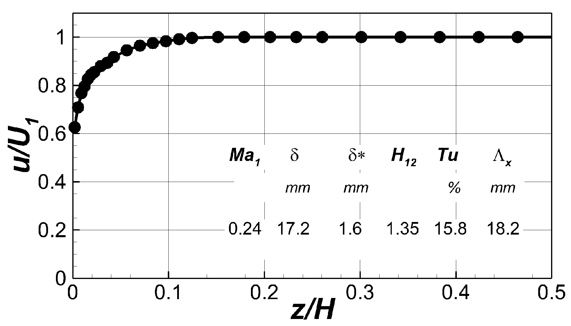
4.1. Cascade Inlet Flow Characterization

Figure 6 shows the Mach number and flow angle distributions measured at X/Cax = −0.5 along the tangential direction for the three tested incidence values. This upstream location was selected since it is far enough from the blade leading edge to be not influenced by the stagnation effect. Inlet flow angle β is defined with respect to the axial direction: according to [27] incidence definition, a negative incidence corresponds to an inlet flow angle larger or less negative than in the design case. The pitch-wise flow distributions show good stability. Moreover, the averaged inlet Mach number Ma1 was always close to 0.24, with a maximum variation in the order of ±1.5% over two pitches, showing a good consistency between the three tested incidence cases. Pitch-wise distributions were averaged to obtain the actual incidence angles reported in Table 2. The flow angle measured at the theoretical 0° incidence case is considered as a reference. The slightly negative incidence measured at the theoretical 0° case is probably due to the turbulence generator, which induces a flow deviation upstream of the cascade, similar to [21,28].

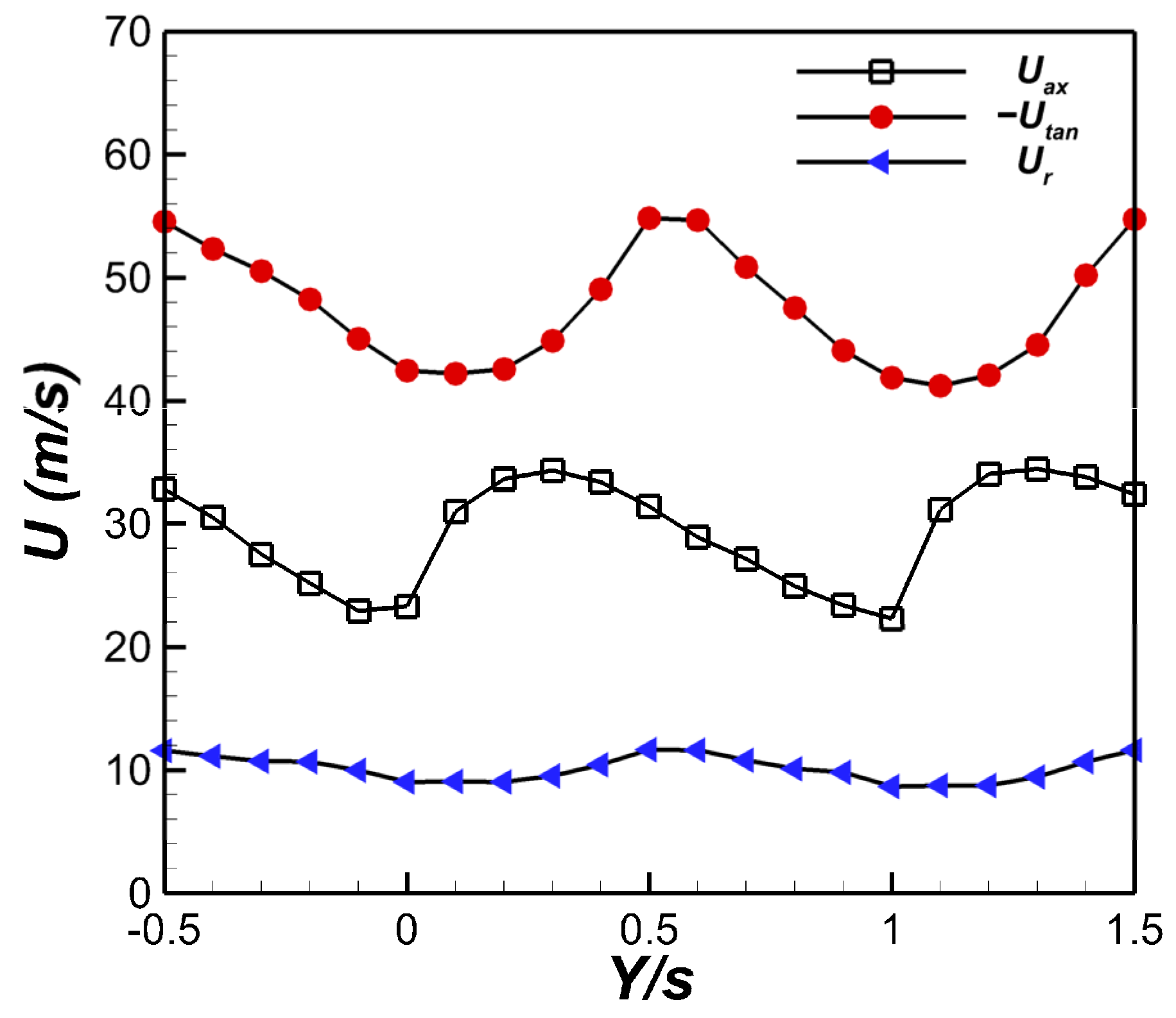
4.2. Purge Flow Characterization

In order to check the quality of purge flow ejection from the slot, coolant flow velocity was measured by the LDV system at the slot exit mid-section. Tests were carried out for a coolant to mainstream mass flow rate ratio MFR = 1.0% at design incidence. Figure 7 shows that the purge flow discharged by the slot is sufficiently periodic in a pitch-wise direction. Pitch-to-pitch variation in the three velocity components was always below ±5.5%. The stagnation effect in front of the blades is evident at Y/s = 0 and 1. The mean purge flow angle in the (Y,Z) plane was 12°, computed by averaging the measured velocity components along the pitch-wise direction.

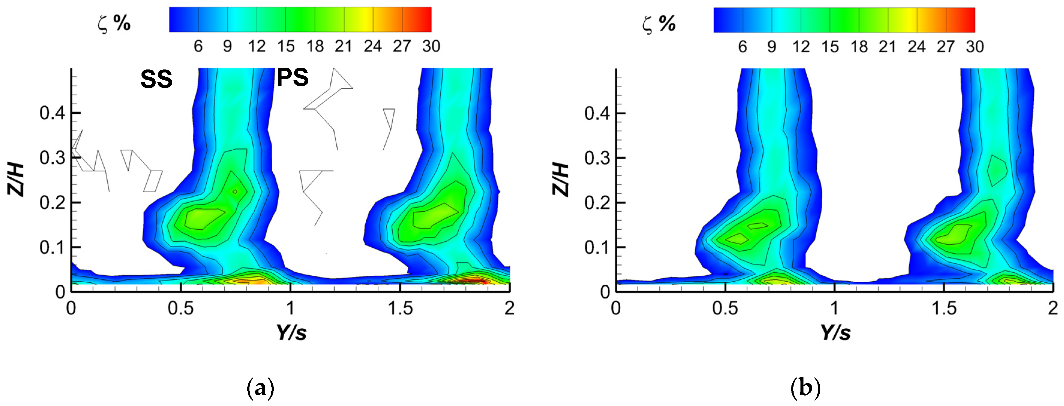
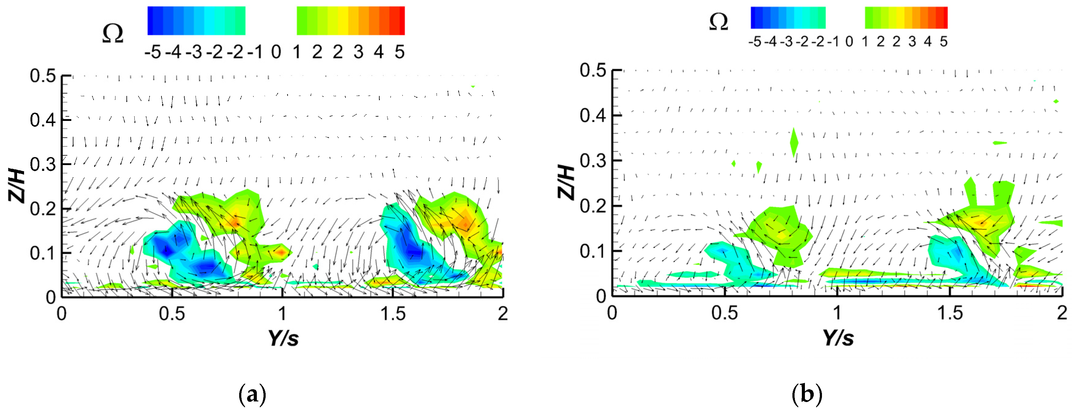
4.3. Local Flow Behavior—Uncooled Cascade

Figure 8 and Figure 9 show the kinetic energy loss coefficient (ζ) distributions and the normalized vorticity (Ω) with superimposed the secondary velocity vectors measured downstream of the trailing edge plane for the design (i = 0°) and the minimum tested incidence angle of −20° with a continuous platform (i.e., without slot). The −10° incidence case is not reported since it is close to the design case. These data are considered as a reference for the following cooled platform investigation.
Two passages are reported to appreciate the flow periodicity at both incidence values tested. Maximum pitch-to-pitch variation in the order of Δζ/ζ = ±4% does exist. At design incidence, the flow downstream of the cascade is characterized by a well-defined passage vortex structure that can be easily identified both from the loss concentration on the suction side of the wakes between Z = 0.1 H and 0.2 H (Figure 8a) and the negative vorticity region in Figure 9a. The counter-clockwise rotating vortical structure with the corresponding positive vorticity related to the trailing shed vortex can also be identified in Figure 8a and Figure 9a. An indication of the presence of a corner vortex can also be seen, corresponding to a second region of high loss close to the wall. A significant passage vortex-related cross flow can also be identified at the wall proximity.
As expected, according to the literature (see, for example, [19]), a decrease in the incidence of negative values gives rise to a reduction in secondary flows. The passage vortex-related loss peaks keep the same intensity but move towards the wall, while the corner vortex intensity reduces (Figure 8b). Vorticity also attenuates together with the endwall cross flow (Figure 9b).

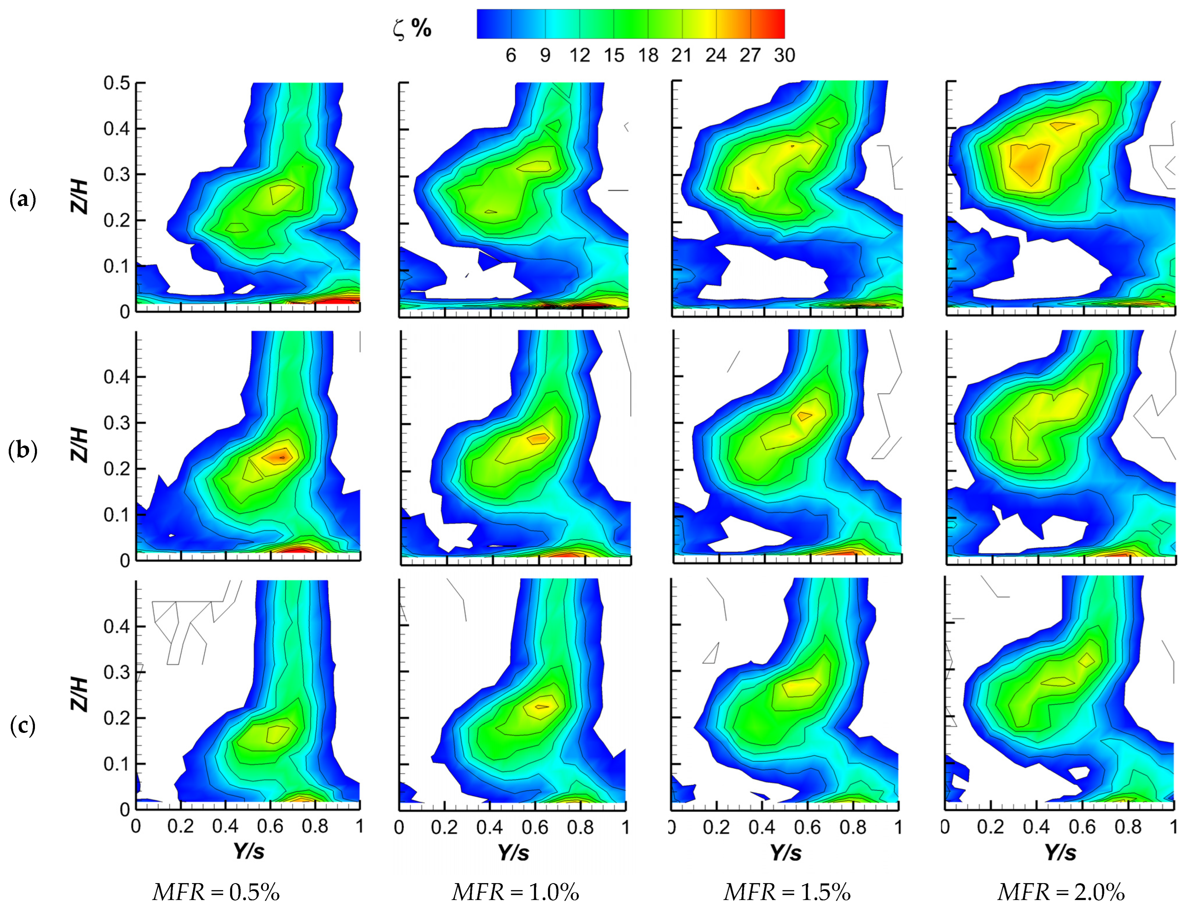
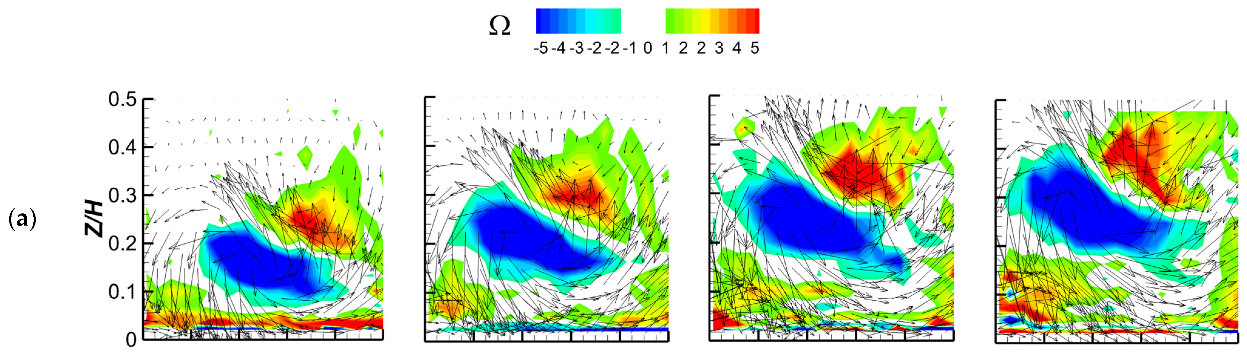
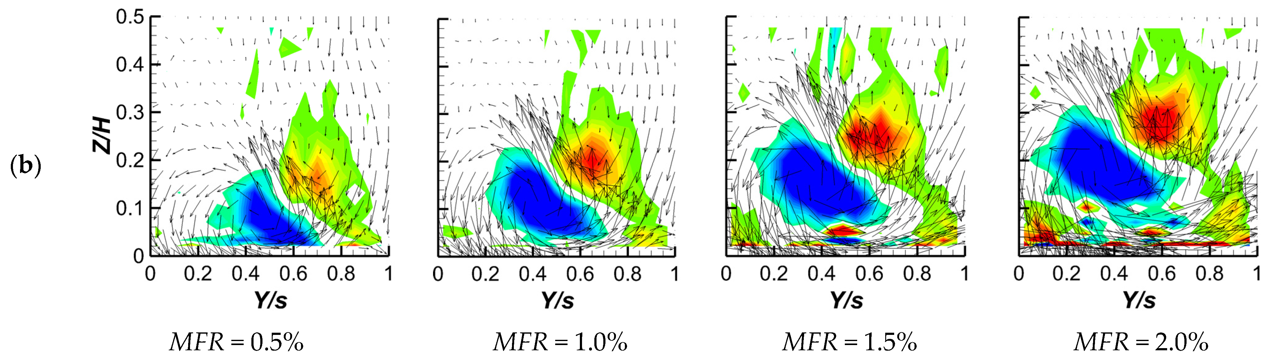
4.4. Local Flow Behavior—Cooled Cascade

Figure 10 shows the impact of incidence variation (from 0° down to −20°) at fixed cascade operating conditions (Ma1 = 0.24 and Tu1 = 7.5%) for the tested coolant to mainstream mass flow ratio MFR values (from 0.5% to 2.0%). Only one pitch is shown, thanks to the good flow periodicity. Figure 11 reports the corresponding vorticity distributions with superimposed secondary velocity vectors. For safe space, only vorticity data belonging to the design (0°) and −20° incidence are reported, as they allow for discussing the general trend even for the −10° case.
As expected [12,18,26], at design incidence (Figure 10a), coolant injection always increases the kinetic energy losses; the greater the injected mass flow, the more it increases. Coolant injection with a negative tangential velocity component (i.e., in the same direction of the passage vortex-related endwall cross flow) enforces the passage vortex that lifts from the wall, resulting in a highly three-dimensional flow structure leaving the cascade. This behavior is consistent with the vorticity distributions shown in Figure 11a for the same testing conditions. The measurement plane is dominated by the passage vortex motion providing the subsequent stator a highly skewed approaching flow. The negative vorticity core corresponding to the trailing shed vortex slightly widens, increasing injection, and moves towards midspan, following the passage vortex displacement.
Reducing the incidence angle to −10° and −20° results in similar behavior when injecting the purge flow at rising MFR (Figure 10b,c and Figure 11b). But, even if the trend is similar for the two tested negative incidence values, the impact on the loss behavior is different. Thanks to the beneficial effect of negative incidence, the passage vortex-related loss core moves back to the wall and reduces in intensity and size, reducing i, as also shown by the vorticity contour maps of Figure 11b. For example, at an MFR of 2.0%, the loss peak decreases from about 25% at 0° to 23% at −10° down to about 15% at −20°. Moreover, at the same MFR of 2.0% and i of −20°, a 2D wake is established at the mid-span section, even if with a limited radial extension. Moreover, the corner vortex trace tangentially moves when incidence reduces from 0° to −10° as a consequence of the reduced endwall cross flow. A further incidence reduction seems to have a marginal impact on the corner vortex.

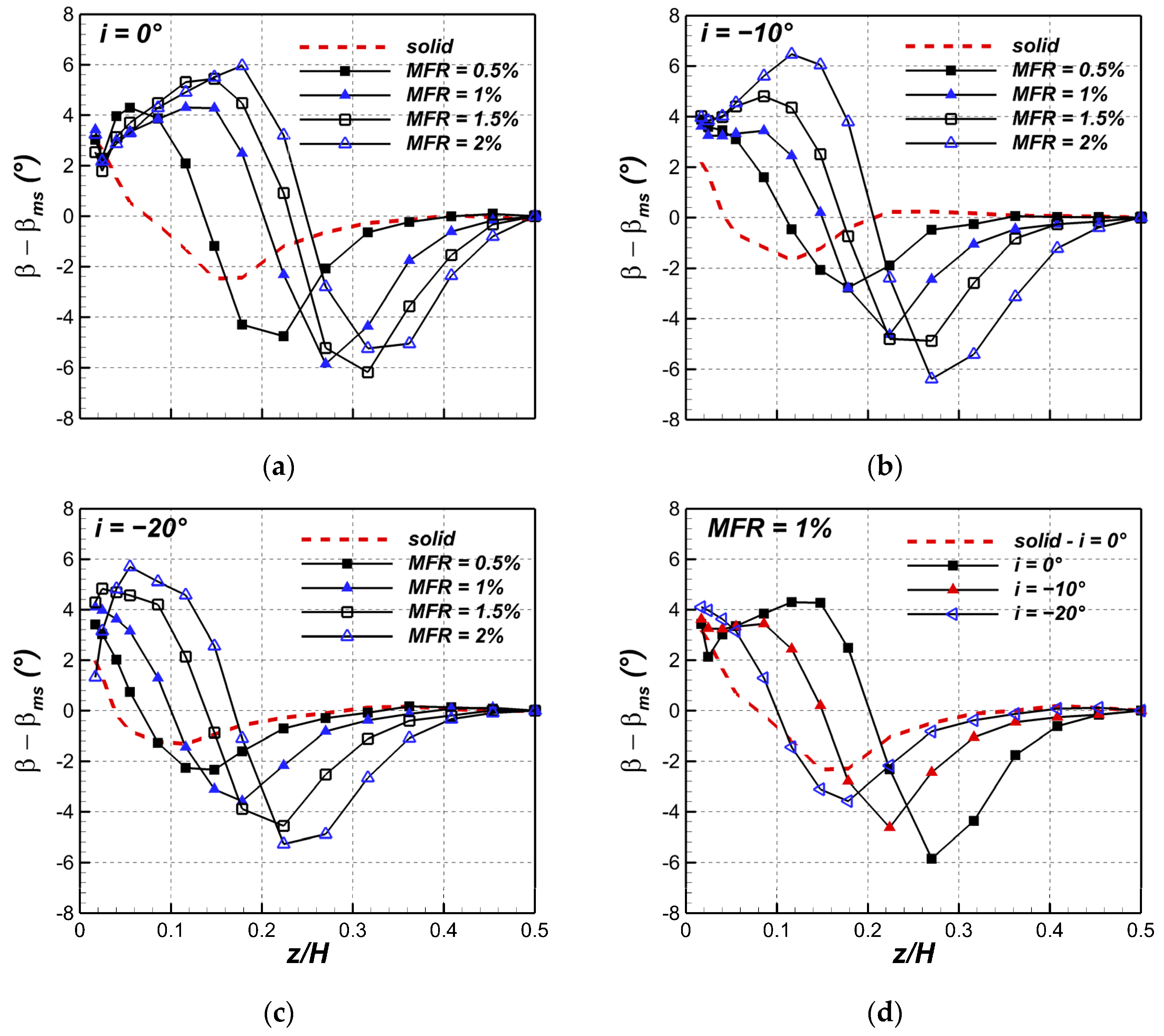
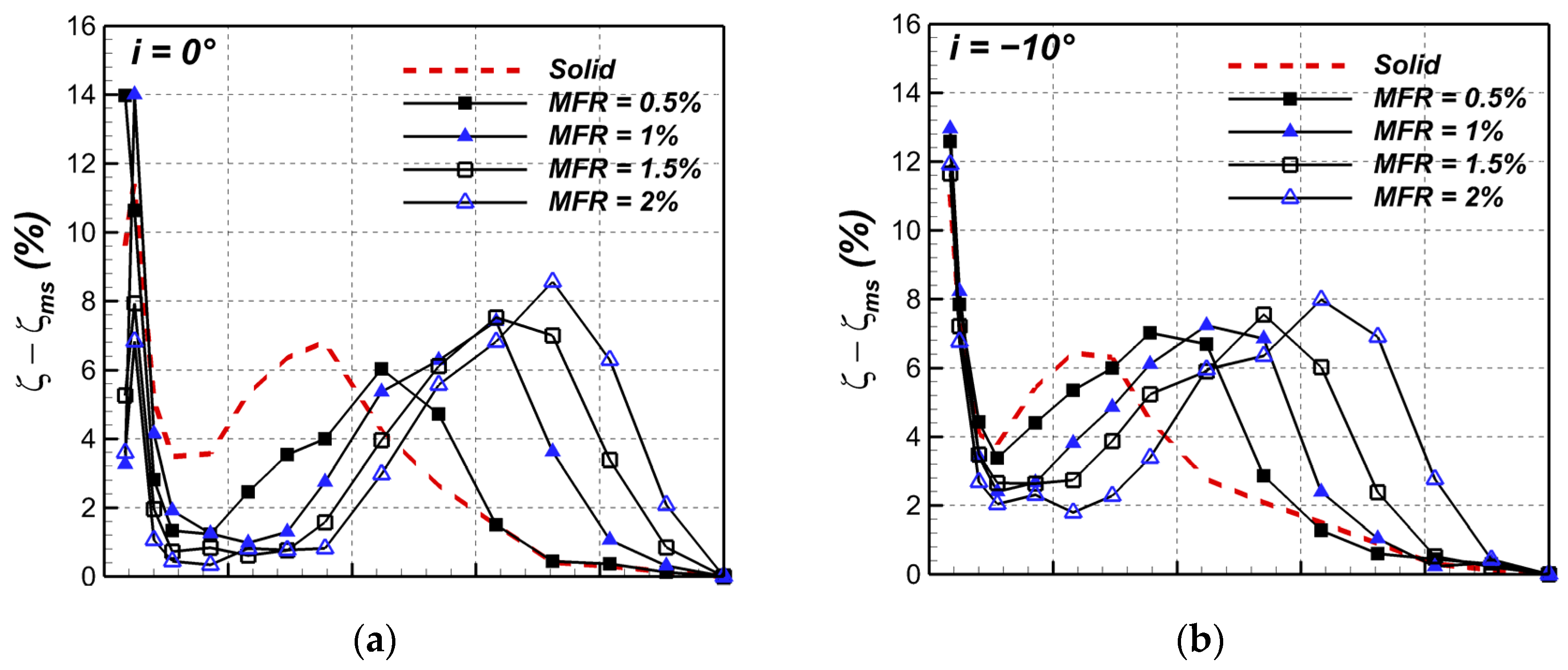
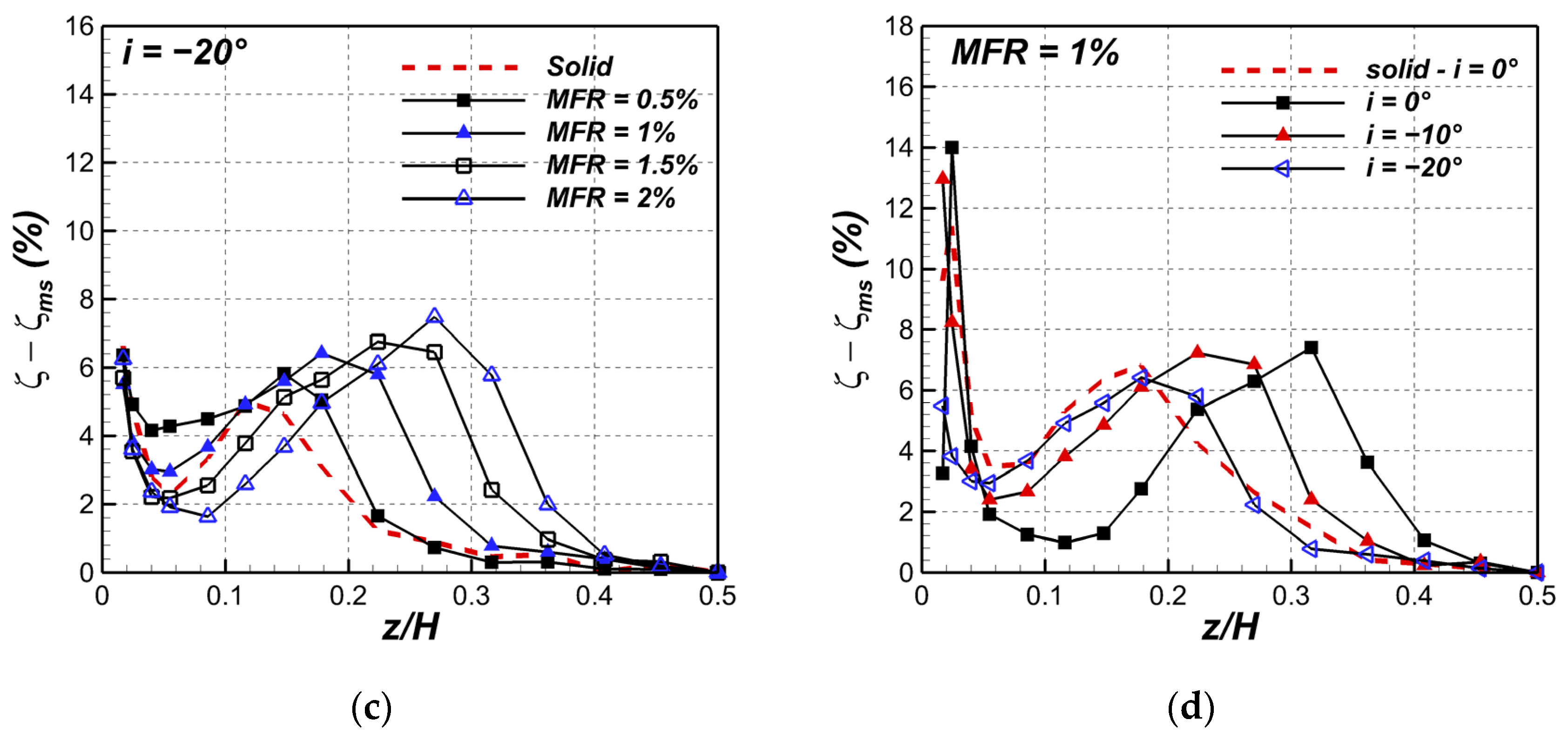
4.5. Span-Averaged Loss and Deviation Angle

To calculate the span averaged distributions of kinetic energy loss coefficient and deviation angle, local data coming from Figure 10 and Figure 11 (Figure 8 and Figure 9 for the solid case) were mass averaged over the pitch. The results are shown in Figure 12 and Figure 13. Reference data related to the uncooled case (no gap–solid endwall) are also reported (dashed lines). At 0° incidence, a rise in the MFR resulted in the increase in the passage vortex loss peak from 6% at MFR = 0.5% to 8.5% at MFR = 2.0%, and in the migration of the same towards mid span. Both underturning and overturning values increase up to −/+6°, with angle variations all over the investigated half span. At −10° incidence, similar behavior is observed, even if with some differences: at low injection rates, the increase in deviation angle is reduced when compared to the design case. The loss increase is similar to the 0° case, but the passage vortex-related loss peak is closer to the wall. At high injection rates, a similar overturning and underturning is observed, but its spanwise extension is reduced. Something similar also happens at the −20° incidence case, with a further loss reduction (the loss peak at MFR = 2.0% is now about 7.5% against 8.5% of the 0° case) and shifts towards the endwall, which also characterizes overturning and underturning.
Finally, Figure 12d and Figure 13d compare the pitch averaged deviation angle and loss coefficient variations along the span at a fixed MFR = 1.0% and variable incidence. These pictures clearly show that injecting the purge flow at 0° incidence results in a significant increase in aerodynamic loss and a huge change in the mean flow angle distribution in the spanwise direction at the exit of the cascade, which could be detrimental to the following stator. Reducing the incidence seems to be advantageous as it reduces losses and helps to confine the change in deviation angle to the endwall region.

4.6. Overall Loss

In order to allow more quantitative comparison between the tested operating conditions, overall mass-averaged energy loss coefficients were computed from flow field data. The so-called primary loss coefficient was computed as follows:
ζ ̿ = U ̿ 2 i s 2 U ̿ 2 2 U ¯ 2 i s , m s 2
This definition was adopted because the calculated values almost coincide with the thermodynamic loss formulation, which also includes coolant internal losses. A maximum difference of 0.44% was observed at MFR = 2.0%. Figure 14 shows the overall mass-averaged kinetic energy loss coefficient for variable MFR at constant incidence. The overall loss coefficient continuously increases, raising the MFR, similar to [12]. Changing the incidence toward negative values does not modify this general behavior but lowers the loss level, especially at −20°. The impact of a −10° incidence is limited, reducing the overall loss coefficient of about −0.5%, whatever the MFR. The loss reduction at −20° is much higher and not constant, reaching −1.6% at MFR = 2.0%.

5. Conclusions

Aerodynamic measurements were carried out in a rotor cascade under realistic engine conditions (Tu1 = 7.5%, Ma2is = 0.55) to evaluate the performance of a platform cooling scheme simulating the stator-to-rotor interface gap at various MFR values between 0.5% and 2.0% with main flow incidence angles of 0°, −10°, and −20°. The objective was to evaluate the aerodynamic performance of this cooled blade cascade by simulating some effects of low-load operating conditions. The key highlights of the present study are the following:
  • As expected, negative incidence reduces secondary flows generation and development across the cascade, reduces the endwall cross flow and overall losses;
  • In the investigated MFR range, increasing the coolant flow rate is detrimental to the cascade performance; the larger the injected mass flow, the higher the loss. This is whatever the incidence of the cascade. In the worst case, i.e., at design incidence, doubling the MFR from 1% to 2% resulted in a loss increase of Δζ = +1.1%;
  • The combination of negative incidence and coolant injection only marginally reduces the loss production at a moderate incidence of −10° (Δζ = −0.5% as an average);
  • A stronger decrease in i down to −20° results in a significant reduction in overall losses, particularly significant at high MFR. When MFR = 2.0%, the loss reduction becomes Δζ = −1.6%;
  • In the presence of a moderate negative incidence, high MFR values could not only be responsible for a huge loss generation but also for the deterioration of flow quality approaching the following stator due to huge variations in the spanwise distribution of ββms.

Author Contributions

Conceptualization, G.B. and H.A.; methodology, G.B., H.A. and N.F.; investigation, H.A.; data curation, G.B.; writing—original draft preparation, G.B. and N.F.; writing—review and editing, G.B. and N.F.; visualization, H.A.; supervision, G.B. All authors have read and agreed to the published version of the manuscript.

Funding

This research received no external funding.

Data Availability Statement

The data presented in this study are available on request from the corresponding author.

Conflicts of Interest

The authors declare no conflict of interest.

References

  1. Ray, A.; De, S. Renewable Electricity Generation—Effect on GHG Emission. In Encyclopedia of Renewable and Sustainable Materials; Hashmi, S., Choudhury, I.A., Eds.; Elsevier: Amsterdam, The Netherlands, 2020; pp. 728–735. [Google Scholar]
  2. BP Statistical Review of World Energy 2022, 71st Edition. Available online: https://www.bp.com/content/dam/bp/business-sites/en/global/corporate/pdfs/energy-economics/statistical-review/bp-stats-review-2022-full-report.pdf (accessed on 1 February 2023).
  3. Owen, J.M. Air-cooled gas–turbine discs: A review of recent research. Int. J. Heat Fluid Flow 1988, 9, 354. [Google Scholar] [CrossRef]
  4. Bozzi, L.; D’Angelo, E.; Facchini, B.; Micio, M.; Da Soghe, R. Experimental Investigation on Leakage Losses and Heat Transfer in a Non- Conventional Labyrinth Seal. In Proceedings of the ASME Turbo Expo 2011: Turbine Technical Conference and Exposition, Vancouver, BC, Canada, 6–10 June 2011. Paper No GT2011-46362. [Google Scholar]
  5. Szyma’ński, A.; Wróblewski, W.; Bochon, K.; Majkut, M.; Strozik, M.; Marugi, K. Experimental validation of optimised straight-through labyrinth seals with various land structures. Int. J. Heat Mass Transf. 2020, 158, 119930. [Google Scholar] [CrossRef]
  6. Nayak, K.C. Effect of Rotation on Leakage and Windage Heating in Labyrinth Seals with Honeycomb Lands. J. Eng. Gas Turbines Power 2020, 142, 4047180. [Google Scholar] [CrossRef]
  7. Fraczek, D.; Bochon, K.; Wroblewski, W. Influence of Honeycomb Land Geometry on Seal Performance. In Proceedings of the ASME Turbo Expo 2016: Turbomachinery Technical Conference and Exposition, Seoul, Republic of Korea, 13–17 June 2016. Paper No GT2016-57569. [Google Scholar]
  8. Barigozzi, G.; Abdeh, H.; Rouina, S.; Franchina, N. The Aero-Thermal Performance of Purge Flow and Discrete Holes Film Cooling of Rotor Blade Platform in Modern High Pressure Gas Turbines: A Review. Int. J. Turbomach. Propuls. Power 2022, 7, 22. [Google Scholar] [CrossRef]
  9. Regina, K.; Kalfas, A.I. Experimental investigation of purge flow effects on a high pressure turbine stage. J. Turbomach. 2015, 135, 041006. [Google Scholar] [CrossRef]
  10. Narzary, D.P.; Liu, K.C.; Rallabandi, A.P.; Han, J.C. Influence of coolant density on turbine blade film-cooling using pressure sensitive paint technique. J. Turbomach. 2012, 134, 031006. [Google Scholar] [CrossRef]
  11. Schuepbach, R.S.; Abhari, M.G.; Rose, T.; Germain, I.; Raab, J.G. Effects of Suction and Injection Purge-Flow on the Secondary Flow Structures of a High-Work Turbine. In Proceedings of the ASME Turbo Expo 2008: Power for Land, Sea, and Air, Berlin, Germany, 9–13 June 2008. Paper No GT2008-50471. [Google Scholar]
  12. Popovíc, I.; Hodson, H.P. Aerothermal impact of the interaction between hub leakage and mainstream flows in highly-loaded high pressure turbine blades. J. Turbomach. 2013, 135, 061014. [Google Scholar] [CrossRef]
  13. Suryanarayanan, A.; Mhetras, S.P.; Schobeiri, M.T.; Han, J.C. Film-Cooling Effectiveness on a Rotating Turbine Platform using Pressure Sensitive Paint Technique. J. Turbomach. 2010, 132, 041001. [Google Scholar] [CrossRef]
  14. Schlienger, J.; Pfau, A.; Kalfas, A.I.; Abhari, R.S. Effects of labyrinth seal variation on multistage axial turbine flow. In Proceedings of the ASME Turbo Expo 2003, Atlanta, GA, USA, 16–19 June 2003. Paper No GT2003-38270. [Google Scholar]
  15. Lynch, S.P.; Thole, K.A. Heat Transfer and film cooling on a contoured blade endwall with platform gap leakage. J. Turbomach. 2017, 139, 051002. [Google Scholar] [CrossRef]
  16. Barigozzi, G.; Franchini, G.; Perdichizzi, A.; Maritano, M.; Abram, R. Purge flow and interface gap geometry influence on the aero-thermal performance of a rotor blade cascade. Int. J. Heat Fluid Flow 2013, 44, 563–575. [Google Scholar] [CrossRef]
  17. MacIsaac, G.D.; Sjolander, S.A.; Praisner, T.J.; Grover, E.A.; Jurek, R. Effects of Simplified Platform Overlap and Cavity Geometry on the Endwall Flow: Measurements and Computations in a Low-Speed Linear Turbine Cascade. In Proceedings of the ASME Turbo Expo 2013: Power for Land, Sea, and Air, San Antonio, TX, USA, 3–7 June 2013. Paper No. GT2013-95670. [Google Scholar]
  18. Popović, I.; Hodson, H.P. The effects of a parametric variation of the rim seal geometry on the interaction between hub leakage and mainstream flows in HP turbines. In Proceedings of the ASME Turbo Expo 2012: Power for Land, Sea, and Air, Copenhagen, Denmark, 11–15 June 2012. Paper No. GT2012-68025. [Google Scholar]
  19. Zhang, Z.; Zhang, Y.; Dong, X.; Qu, X.; Lu, X.; Zhang, Y. Flow mechanism between purge flow and mainstream in different turbine rim seal configurations. Chin. J. Aeronaut. 2020, 33, 2162. [Google Scholar] [CrossRef]
  20. Perdichizzi, A. Mach Number Effects on Secondary Flow Development Downstream of a Turbine Cascade. In Proceedings of the ASME 1989 International Gas Turbine and Aeroengine Congress and Exposition, Toronto, ON, Canada, 4–8 June 1989. [Google Scholar]
  21. Abdeh, H.; Barigozzi, G.; Perdichizzi, A.; Henze, M.; Krueckels, J. Incidence Effect on the Aero-Thermal Performance of a Film Cooled Nozzle Vane Cascade. J. Turbomach. 2019, 141, 4041923. [Google Scholar] [CrossRef]
  22. Chen, A.F.; Shiau, C.C.; Han, J.C. Turbine blade platform film cooling with simulated swirl purge flow and slashface leakage conditions. J. Turbomach. 2017, 139, 031012. [Google Scholar] [CrossRef]
  23. Schreiner, B.D.; Wilson, M.; Li, Y.S.; Sangan, C.M. Effect of Purge on the Secondary Flow-Field of a Gas Turbine Blade-Row. J. Turbomach. 2020, 142, 4047185. [Google Scholar] [CrossRef]
  24. Abdeh, H.; Barigozzi, G.; Franchina, N. Rotor Cascade Assessment at Off-Design Condition: An Aerodynamic Investigation on Platform Cooling. In Proceedings of the 15th European Turbomachinery Conference, Paper N. ETC2023-131, Budapest, Hungary, 24–28 April 2023; Available online: https://www.euroturbo.eu/publications/conference-proceedings-repository (accessed on 4 June 2023).
  25. Barigozzi, G.; Perdichizzi, A.; Pestelli, L.; Abram, R. Combined Experimental and Numerical Investigation of the Aero-Thermal Performance of a Rotor Blade Cascade with Platform Cooling. In Proceedings of the ASME Turbo Expo 2019: Turbomachinery Technical Conference and Exposition, Phoenix, AZ, USA, 17–21 June 2019. Paper No. GT2019-91601. [Google Scholar]
  26. Barigozzi, G.; Franchini, G.; Perdichizzi, A.; Maritano, M.; Abram, R. Influence of purge flow injection angle on the aerothermal performance of a rotor blade cascade. J. Turbomach. 2014, 136, 041012. [Google Scholar] [CrossRef]
  27. Craig, H.R.M.; Cox, H.J.A. Performance Estimation of Axial Flow Turbines. Proc. Inst. Mech. Eng. 1971, 187, 32–71. [Google Scholar] [CrossRef]
  28. Chavez, K.F.; Packard, G.R.; Slavens, T.N.; Bogard, D.G. Experimentally Determined External Heat Transfer Coefficient of a New Turbine Airfoil Design at Varying Incidence Angles. In Proceedings of the 16th International Symposium on Transport Phenomena and Dynamics of Rotating Machinery ISROMAC 2016, Honolulu, HI, USA, 10–15 April 2016. [Google Scholar]
Figure 1. Wind tunnel.
Ijtpp 08 00023 g001
Figure 2. Rotor blade cascade.
Ijtpp 08 00023 g002
Figure 3. Setup for i = −20°.
Ijtpp 08 00023 g003
Figure 4. Inlet boundary layer (X/Cax = −1).
Ijtpp 08 00023 g004
Figure 5. Platform cooling scheme.
Ijtpp 08 00023 g005
Figure 6. Approaching flow characterization (X/Cax = −0.5): (a) Ma1; (b) β.
Ijtpp 08 00023 g006
Figure 7. Purge flow characterization at slot exit (i = 0°).
Ijtpp 08 00023 g007
Figure 8. Kinetic energy loss coefficient distributions—uncooled case: (a) 0°; (b) −20° incidence.
Ijtpp 08 00023 g008
Figure 9. Vorticity and secondary velocity vectors—uncooled case: (a) 0°; (b) −20° incidence.
Ijtpp 08 00023 g009
Figure 10. Kinetic energy loss coefficient distributions for variable MFR: (a) 0°; (b) −10°; (c) −20° incidence.
Ijtpp 08 00023 g010
Figure 11. Ω distributions for variable MFR: (a) 0°; (b) −20° incidence.
Ijtpp 08 00023 g011aIjtpp 08 00023 g011b
Figure 12. β − βms for variable MFR: (a) 0°; (b) −10°; (c) −20°; (d) at fixed MFR = 1.0% and variable i.
Ijtpp 08 00023 g012
Figure 13. ζ for variable MFR: (a) 0°; (b) −10°; (c) −20°; (d) at fixed MFR = 1.0% and variable i.
Ijtpp 08 00023 g013aIjtpp 08 00023 g013b
Figure 14. Overall ζ for variable MFR and i.
Ijtpp 08 00023 g014
Table 1. Cascade geometry and nominal operating conditions.
Cascade GeometryOperating Conditions
s/C = 0.637Ma2is = 0.55
H/C = 1.24Tu1 = 7.5%
β1 = −30.87°Re2is = 1.51 × 10⁶
Table 2. Inlet incidence angle for variable testing conditions.
i Theoretical (°)β (°)i Actual (°)
0−29.8−1.1
−10−20.8−10.1
−20−10.6−20.3
Disclaimer/Publisher’s Note: The statements, opinions and data contained in all publications are solely those of the individual author(s) and contributor(s) and not of MDPI and/or the editor(s). MDPI and/or the editor(s) disclaim responsibility for any injury to people or property resulting from any ideas, methods, instructions or products referred to in the content.

