Article

Operating Range Extension of an Open Impeller Centrifugal Compressor Stage Utilising 3D Diffuser End Wall Contouring †

1
Institute of Power Plant Technology, Steam and Gas Turbines, RWTH Aachen University, Mathieustr. 9, 52074 Aachen, Germany
2
MAN Energy Solutions Schweiz AG, Hardstrasse 319, 8005 Zurich, Switzerland
*
Author to whom correspondence should be addressed.
This paper is an extended version of our paper published in the Proceedings of the 13th European Conference on Turbomachinery Fluid dynamics & Thermodynamics (Paper ID ETC2019-156).
Int. J. Turbomach. Propuls. Power 2020, 5(1), 4; https://doi.org/10.3390/ijtpp5010004
Submission received: 31 October 2019 / Revised: 16 January 2020 / Accepted: 29 January 2020 / Published: 7 February 2020

Abstract

:
State-of-the-art centrifugal compressor units utilised in pipeline and in energy storage applications face the challenge of flexible and highly efficient operation. Geometric contouring on the hub side near a vaned diffuser affects the flow in a way which increases operational flexibility by delaying the incipience of instability and thereby increases compressor operating range. In the present paper, a hub-side wall contouring is applied within the vaneless space and the vaned diffuser of an open impeller centrifugal compressor stage. The performance characteristic of the novel hub contouring is evaluated in a scale-model test rig and compared against a baseline design. A stable operating range increase of 8% is achieved for the contoured design at Mu 2 = 1.16. 5-hole probe measurements covering a complete diffuser blade-to-blade passage are performed upstream the diffuser and compared both against CFD simulations and against the measurements of the baseline design for an operating point near the stability limit.

Graphical Abstract

1. Introduction

Numerous attempts have been made to increase the stable operating range of centrifugal compressor stages with minimal loss of stage efficiency. An overview on strategies for operating range extension as well as on their impact on compressor stability and efficiency is given by Japikse [1] and Al-Busaidi and Pilidis [2]. A previously described strategy involves increasing the diffuser inlet flow angle at low flow rates. Botros and Henderson [3] give a review on design methods, which can advantageously influence diffuser operating range. The flow rate at choking was increased through integration of a hub-sided groove at diffuser inlet and a rotating external hub wall with radial slots. State-of-the-art compressor units, utilized in storage technologies as well as in industrial pipeline applications, are required to provide flexibility at high efficiency levels. A wide stable operating range of vaned diffusers is therefore important to meet these requirements. Fujisawa et al. [4] and Fujisawa et al. [5] studied the diffuser stall mechanism in an open impeller centrifugal compressor stage with a wedge diffuser. As initiation for diffuser instability a rotating diffuser stall was observed on shroud side. Spakovszky [6] applied an air injection method within the vaneless space on shroud side of an open impeller centrifugal compressor with a vaned diffuser. Through flush mounted nozzles, compressed air entered the flow channel circumferentially along the shroud-side wall. As a result, the flow area in the vaneless space is decreased. This blockage leads to a range extension of 25% in surge-margin. At highly-loaded operating conditions in a turbocharger centrifugal compressor Spakovszky and Roduner [7] again regulated operating range through recirculating air from the volute into the vaneless space by means of shroud-side slots. The recirculated air is used to partly recover a reduction of stable operating range due to an unavoidable hub side bleed air extraction at the impeller exit. Skoch [8] injected air by means of nozzles into the shroud-side vaneless space. A range extension along with a decrease in stage’s total pressure ratio was measured. In contrast to these active strategies, there are also passive attempts to improve stable operating range. The presence of shroud-sided inserted control tubes, which cause an obstruction to the flow upstream the diffuser leading edge near the shroud wall, showed that surge margin could be extended by about 9.3% [8]. It was shown that reducing the circumferential velocity component in the vaneless space was key to extend the stable operating range. Porous throat diffusers are successfully utilized for an improvement in compressor stability limit. At high pressure ratios, Galloway et al. [9] increased the stable flow range by up to 26.8% by applying a porous throat diffuser. Ohta et al. [10] experimentally and numerically examined diffuser vanes with cut back leading edges in a centrifugal compressor. For the hub-sided cut back diffuser vanes a range extension was observed. By Skoch [11] the influence of hub-sided air injection on operation range is examined. The injection nozzles were flush mounted within the vaneless space. Without injecting fluid, an operating range extension was observed for nozzles oriented in a way, which obstructed the circumferential flow component.
Past studies indicate that both passive and active means to increase operating range may be utilized as a basis for the present study. However it is essential that the vaned diffuser is the decisive component for stage stability. Large incidence flow angles at the shroud-side diffuser vane leading edge are assumed to cause flow separation at diffuser vane’s suction side. It is proposed in the present study, that applying of an end wall contouring on hub side, the reduction of area within the vaneless space and in the area of the diffuser leading edge leads to a local acceleration of the flow and therefore the incidence angle at diffuser leading edge, especially on the shroud side, can be reduced at operating points near the stability limit, thereby increasing the stable operating range towards lower flow coefficients. Within this study, the performance characteristics for a baseline and the contoured diffuser design are compared with regard to stability limit. Furthermore, 5-hole probe measurements are performed within the vaneless space. The measurement data is compared to the CFD simulations, which are used to gain a precise insight on the influence of the hub side wall contouring on the diffuser flow field.

2. Numerical Model

A numerical study to evaluate different end wall contouring designs was conducted. A grid independency study was performed resulting in the chosen grid resolution of 4.7 million nodes. All CFD simulations were performed with the commercial solver NUMECA FINE/Turbo Version 12.1. The computational domain includes the impeller, the diffuser as well as the side cavity including the labyrinth sealing configuration utilized in the test facility. Impeller and diffuser were meshed as single passages. The computational domain is shown in Figure 1. A full non matching rotor-stator interface was chosen between the impeller and the diffuser. The connection between side cavity and main flow channel was realized by means of a full non matching boundary connection. The tip gap of the impeller blades as well as the fillets in impeller and diffuser were meshed. At the impeller inlet plane, total pressure and total temperature were imposed. At the diffuser outlet, the mass flow rate corresponding to the measured values at the test rig was imposed. At side cavity outlet, the total pressure of the impeller inlet plane was imposed. The boundary layer was resolved with an average y+ around 1 and Spalart-Allmaras turbulence model as well as basic harmonic method were utilized for calculations.

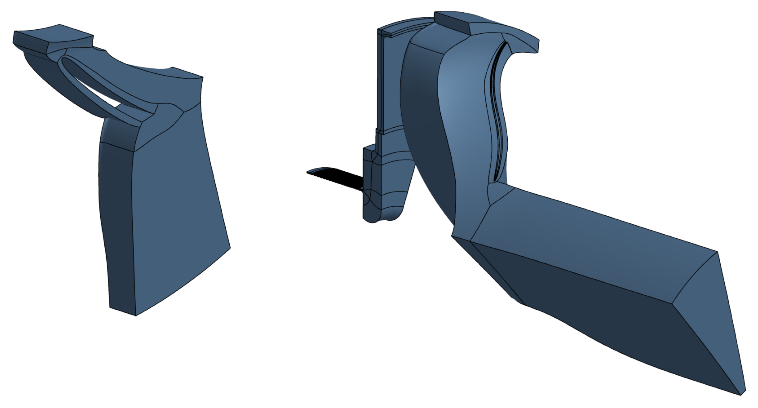
3. Diffuser Modification with Hub Side Wall Contouring

Starting from the baseline design, the contoured diffuser’s hub side wall is redesigned and the operating range extension for several design variations is predicted by means of CFD simulations. The best diffuser design is selected with regard to range extension with negligible performance loss. In Figure 2, the designed shape of the hub side wall is illustrated. The thickening on the pressure sided hub side wall near the leading edge creates a bump to about 8% channel height, the depth of the downstream indentation is about 5% channel height.
The idea behind the diffuser concept is for near stability limit operation, where the flow entering the diffuser has a large circumferential component, the contouring creates an acceleration of the flow within the vaneless space near the leading edge resulting in a more radial flow at the diffuser vane leading edge. Thus the incidence of the flow is reduced—especially near the shroud wall—and flow separation on the suction side of the vanes is delayed. Thickening within the diffuser passages leads to a reduction in throat area. To compensate, an indentation was integrated on the hub inside the passage downstream the leading edge. For both diffuser designs (baseline and contoured design), the same vane shape, fillets and periodicity apply. The 2D-blade profile remains constant over channel height.

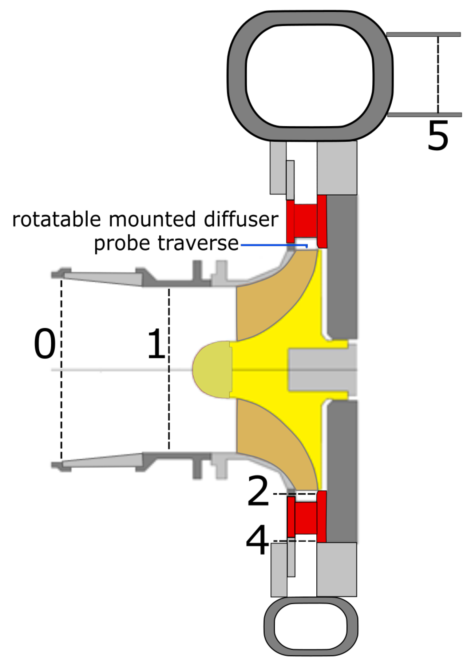
4. Experimental Setup

At the Institute of Power Plant Technology, Steam and Gas Turbines (IKDG), at RWTH Aachen University, a scale-model test rig is used for aerodynamic radial compressor component and stage testing. An open test loop provides low pressure losses inside test fluid piping, allowing operating points at low pressure ratios (choke conditions) to be measured. The stage’s impeller outer diameter is 280 mm. The impeller is directly connected to a planetary gear box providing a wide variable speed range. A direct current motor provides an electrical power output of 660 kW.
Figure 3 gives an schematic overview of the rig’s testing section. All measurements are conducted without preswirl at the impeller inlet (plane 0). A venturi nozzle is utilized to determine mass flow rate upstream the stage. Total temperature is measured in planes 0 and 5, static wall pressure is measured in all planes. Additionally, shroud-side transient wall pressure signals are recorded at three circumferential positions for planes 1, 2 and 4 to insure rotating stall cells are detected near the stability limit.
A pneumatic 5-hole probe is installed and traverses through the flow field within the cylindrical plane 2 in the vaneless space upstream of the diffuser vane leading edge. Both, its probe head diameter as well as its shaft width are equivalent to 6% channel height. In Figure 4, this plane as well as the definition of flow angles are illustrated. In the radial circumferential plane, the circumferential flow angle α is the flow angle from the circumferential direction. For example, a pure circumferential flow has an α value of 0 , a pure radial flow has an α value of 90 . The cross flow angle β is defined as the flow angle between the radial velocity component and the absolute flow velocity vector’s projection on the radial axial plane. A motor-controlled step-by-step rotatable diffuser enables probe traversing at diffuser positions covering at least one diffuser passage. The diffuser position is measured inductively with a circumferential resolution of <0.0013 at the diffuser ring itself. The probe head is adjusted with the local circumferential flow angle by probe rotation. The circumferential flow angle adjustment is resolved with <0.044 and the resolution in axial probe head position is 5 μ m. The measured probe data provide flow direction, flow velocity and static and total pressure distribution. In order to cover a wide Mach number and flow angle detection range, the probe is calibrated within a range of ±20 in circumferential flow angle α and cross flow angle β referring to a zero incidence flow at probe head and from local Mach number 0.3 up to 0.9 in steps of Ma = 0.1. Corresponding to a confidence level of 2 σ local Mach number is measured with an uncertainty of ±0.01, cross flow angle β with ±0.7 and circumferential flow angle α with ±0.6 .

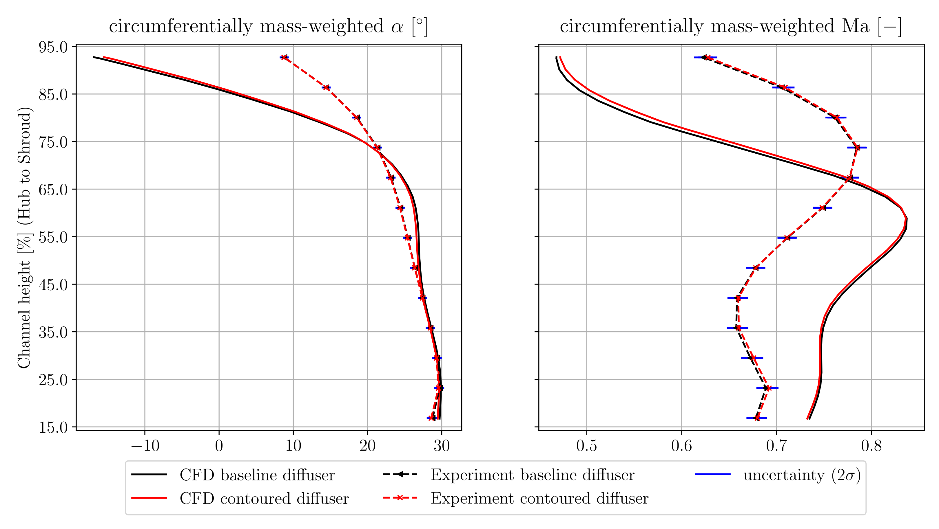
5. Comparison of Numerical Prediction and Experiment
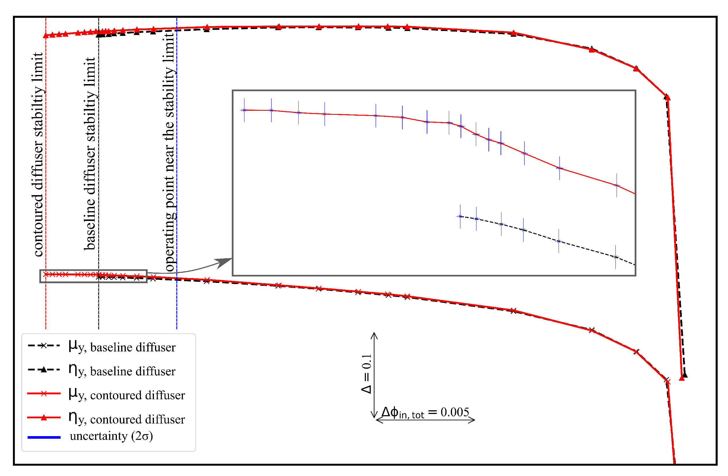
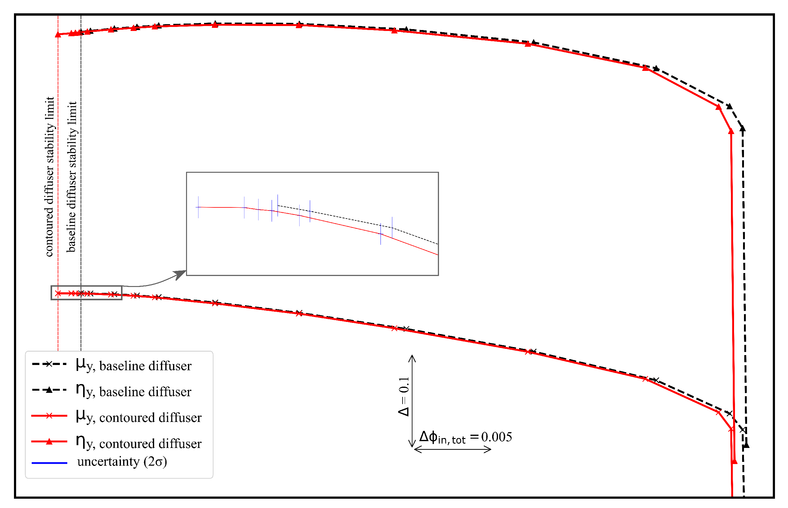
The experimental data provided by the 5-hole probe is utilized to assess the CFD model. The evaluation of the CFD results is undertaken for both the baseline and the contoured diffuser configuration. In Figure 5, a comparison between numerical prediction and experiment of the circumferentially mass-weighted axial distribution of the circumferential flow angle and of the local Mach number for an operating point near the stability limit at stage Mach number Mu 2 = 1.16 is shown.
Below 75% channel height, the axial distribution of the mass-weighted circumferential flow angle is in good agreement between CFD prediction and experiment for both configurations. Near shroud wall, a flow separation for both the contoured and the baseline configuration is predicted, whereas no negative mass-weighted circumferential flow angles are observed in the measurements. For the circumferentially mass-weighted local Mach numbers a similar trend is shown, but due to the predicted shroud side flow separation in both configurations, the predicted averaged local Mach number is smaller than in the corresponding experiment near shroud. In order to have agreement in mass flow for both CFD and experiment, the predicted circumferentially averaged local Mach number is higher compared to the corresponding measured values below 67% channel height and is lower above 67% channel height. The deviations between the predicted mean local Mach numbers and the corresponding measured mean local Mach numbers are less than 0.1%.

6. Results

During the measurements at IKDG testing facility, the overall performance for both the baseline and the end wall contoured diffuser configuration was precisely evaluated and compared with respect to the polytropic pressure coefficient and the polytropic total-to-total efficiency. To provide an analytical measure to assess and quantify the effectiveness of the contoured diffuser design, the range extension factor REF is calculated based on Equation (1) for each operating speed. REF is defined as the ratio of the corresponding differences of flow coefficient at choke and at stability limit for the contoured to the baseline diffuser configuration. The choke flow coefficient is the maximum flow coefficient for the given speed.
REF = ϕ i n , t o t , contoured diffuser , choke ϕ i n , t o t , contoured diffuser , stability limit ϕ i n , t o t , baseline diffuser , choke ϕ i n , t o t , baseline diffuser , stability limit
The criterion of compressor stage stability is a negative slope of the polytropic pressure coefficient. This criterion is implemented into a stability limit detection method and is applied for every measured speed line. The flow coefficient at the stability limit is determined by using Equations (2) and (3).
ϕ i n , t o t , stability limit = min ( ϕ i n , t o t ( μ y , i ) , ϕ i n , t o t ( μ y , i + 1 ) ) i speed line
with μ y , i > μ y , i + 1 ϕ i n , t o t ( μ y , i ) < ϕ i n , t o t ( μ y , i + 1 )
In Figure 6, the measured performance characteristic of the baseline and of the contoured diffuser configuration for stage Mach number Mu 2 = 1.16 are shown. The stability limit based on Equations (2) and (3) is marked for both configurations. All plotted points fulfill the compressor stage stability criterion. Near the stability limit, transient wall pressure measurements were conducted in order to quantify phenomena such as rotating cells and surge. No rotating stall cells were detected. Furthermore, an uncertainty analysis was conducted providing standard deviations with a confidence level of 2 σ displayed in Figure 6. At stage Mach number Mu 2 = 1.16 a range extension of 8% (REF = 1.08) is achieved due to hub end wall contouring. Furthermore, the polytropic total-to-total efficiency is slightly increased, most pronounced near the stability limit. In Figure 7 the performace characteristics of both the contoured diffuser configuration and the baseline diffuser configuration are shown at design stage Mach number Mu 2 = 1.0. A range extension of 2% is achieved for the contoured diffuser configuration. During the contoured diffuser’s choke operation, the maximum measured flow coefficient is reduced compared to the baseline design. Thereby the performance characteristic is shifted towards lower flow coefficients. At choke limit at Mu 2 = 1.0, this characteristic shift is due to a throat area reduction caused by the applied thickening near the contoured diffuser’s leading edge.

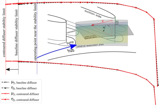
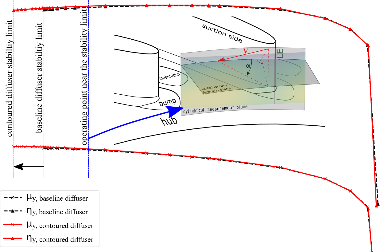
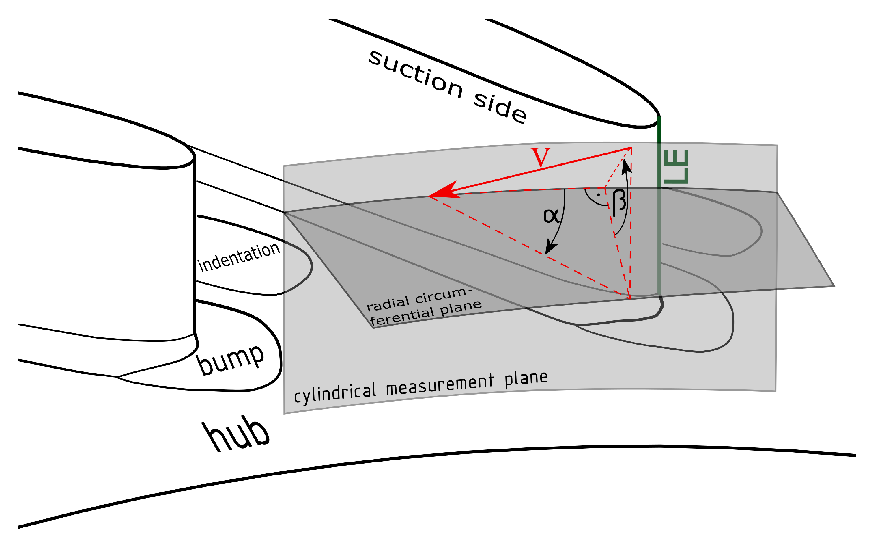
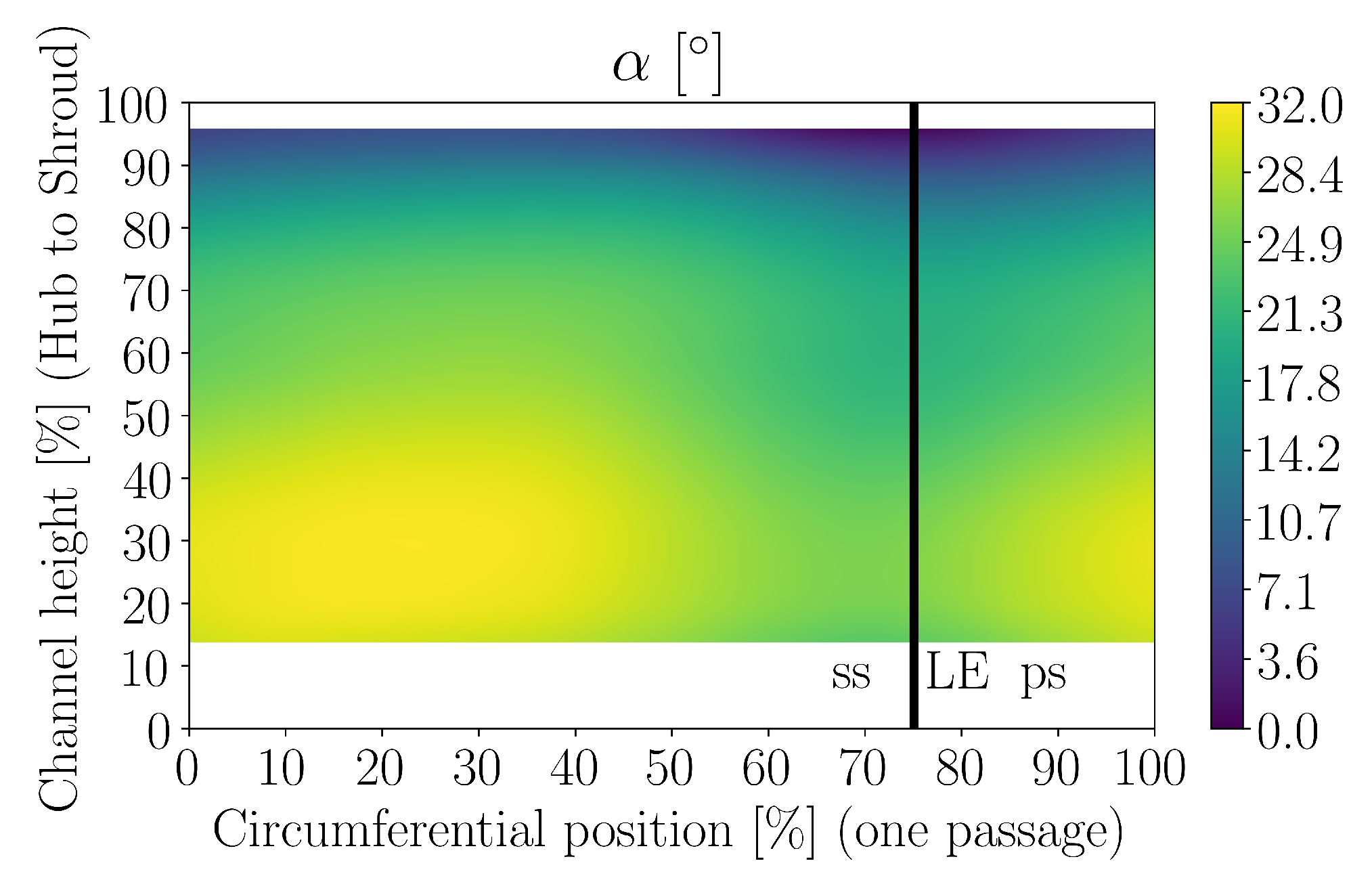
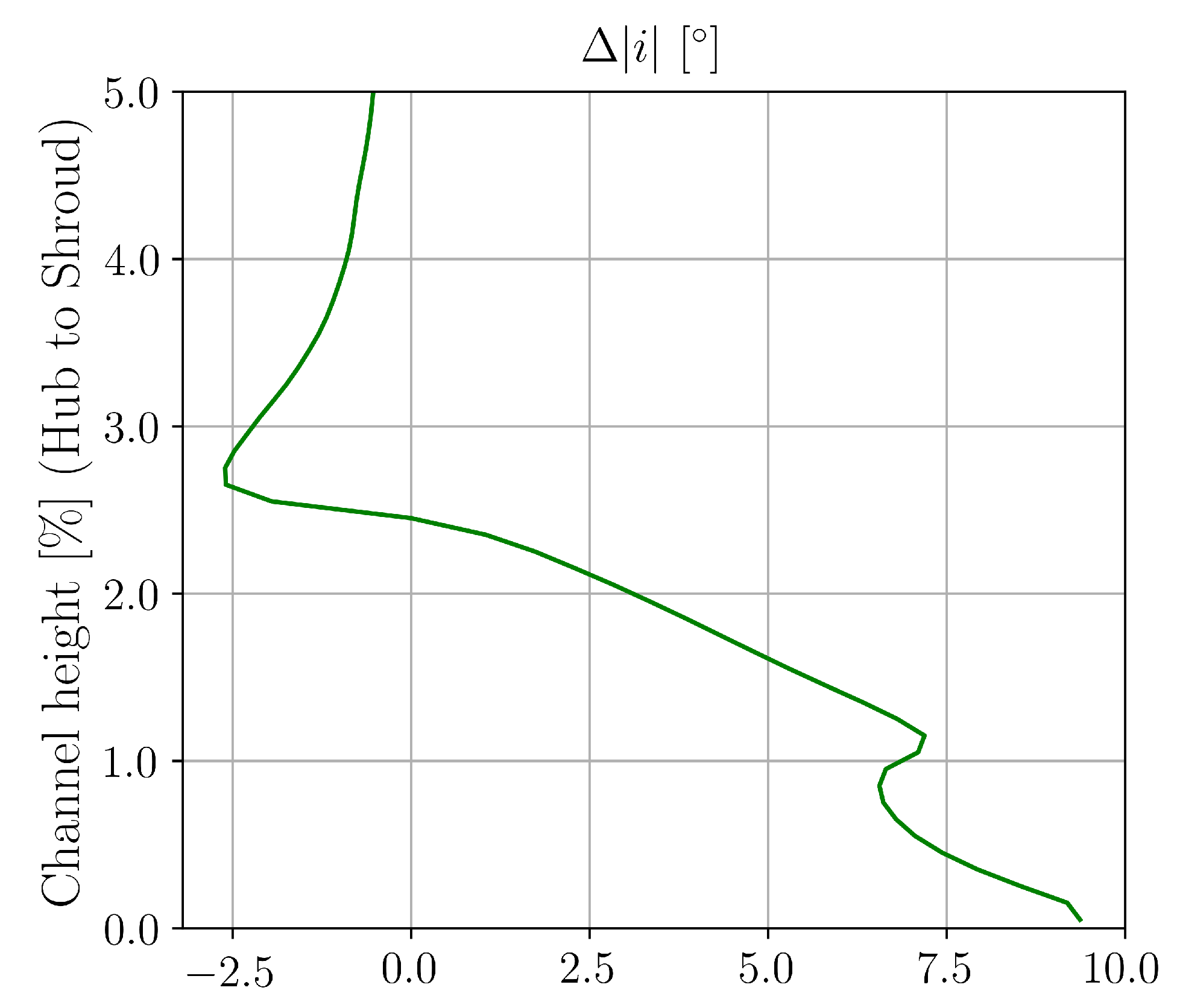
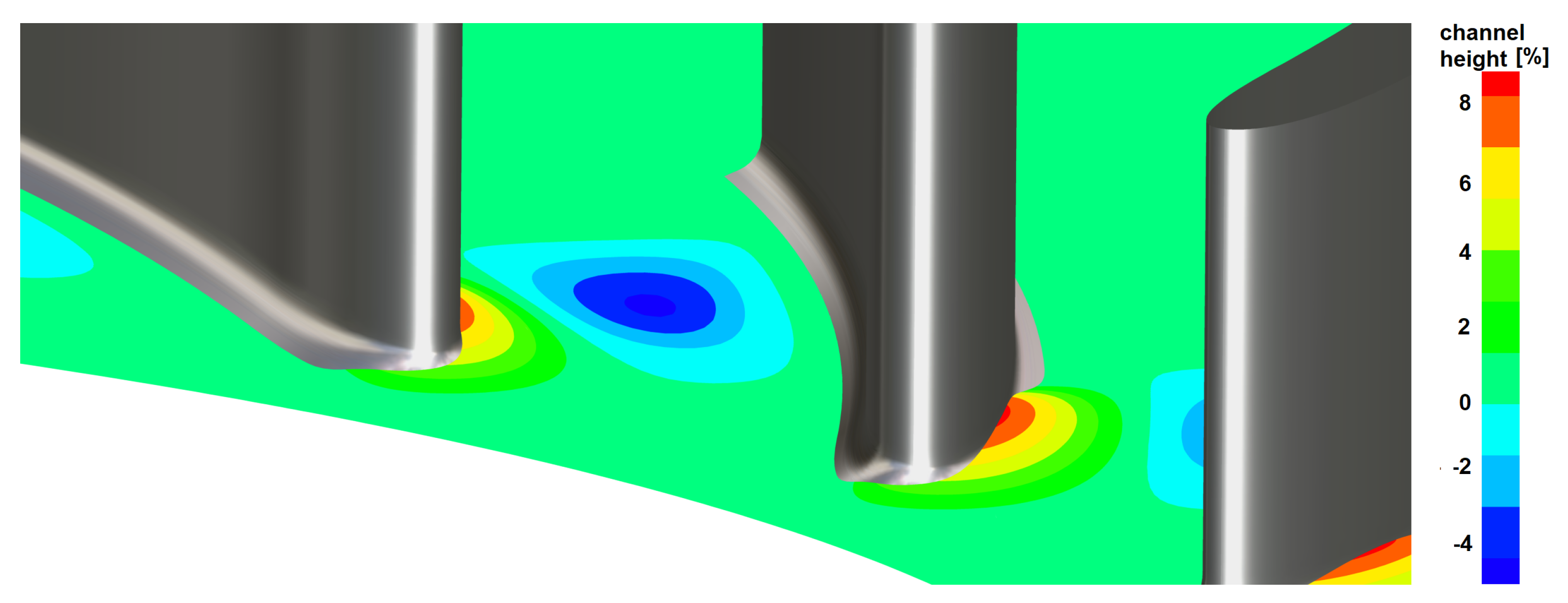
6.1. Detailed Evaluation of Flow Field in Vaneless Space

For both speed lines illustrated in Figure 6, a detailed analysis of the flow field is conducted by means of the 5-hole probe in an operating point near the stability limit. The operating point is also marked in Figure 6. To assess the flow stabilizing effect of the hub wall contouring, the improvement in incidence of the contoured diffuser configuration compared to the baseline configuration is used for quantification. As shown in Equation (4), a reduction of the absolute value of the incidence results in a positive value of Δ | i | . Negative results indicate a more circumferential flow direction and therefore an increase in absolute incidence. In Equation (4), α design is defined as the diffuser vane leading edge metal angle.
Δ | i | = | α design α baseline diffuser | | α design α contoured diffuser |
In Figure 8, the measured circumferential flow angle distribution as well as the downstream leading edge (LE) as defined in Figure 4 are presented for the baseline configuration at stage Mach number Mu 2 = 1.16 for the operating point near the stability limit. On the abscissa, one blade-to-blade passage of the measurement plane and on the ordinate axis channel height from hub to shroud are plotted. The measurement plane has a point distribution with a grid of 21 × 14 probe positions to ensure that flow areas with high gradients are sufficiently resolved. Near shroud the measured circumferential flow angle values are about 7 and less, which indicate a strongly circumferential flow within the vaneless space, and therefore have a high degree of diffuser incidence. In the area close to the downstream leading edge, the observed circumferential flow angle is further reduced, especially near the shroud wall.
Figure 9 illustrates the measured improvement in incidence Δ | i | within the measurement plane. The incidence of the contoured diffuser configuration is improved in close proximity of the diffuser’s leading edge. In a wide region, which comes up from hub to shroud improvements in incidence of about 0.5 are quantifiable. For the contoured diffuser configuration, a more radial flow field is measured particularly in a region upstream the vane’s pressure side and therefore improved incidence angles (see Equation (4)) are observed. The improvements in incidence as well as in circumferential flow angle are assumed to stabilize the flow downstream the measurement plane. Furthermore, it is assumed that all deflections of circumferential flow angle are caused by the end wall contouring, leading towards a more radial flow direction and therefore to a reduction in incidence in regions with high circumferential velocity components, in turn causing the increase in stability limit.

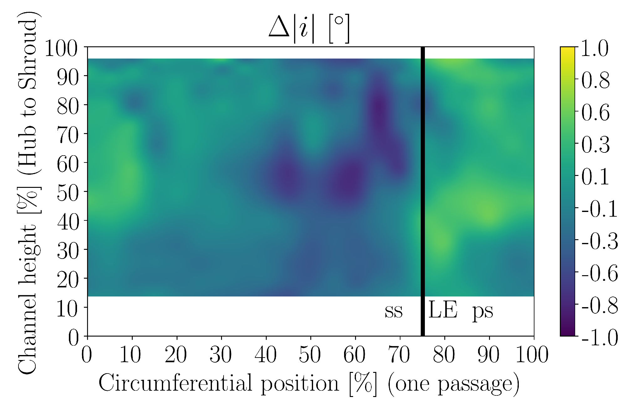
6.2. Effect of Hub Wall Contouring on Flow Field in Vaned Diffuser

In order to visualize the effect of the hub wall contouring on the simulated flow field, a plane within the vaned diffuser at 5% channel height is displayed in Figure 10. The normalized magnitude of absolute velocity is illustrated for the baseline (top) and for the contoured diffuser (bottom) at stage Mach number Mu 2 = 1.16 at the near stability limit operating point. The chosen cutting plane intersects the contouring’s bump on the diffuser vane’s pressure side. For the baseline diffuser, regions of overspeed are clearly visible on the suction side (region I) as well as on the pressure side (region II) near the vane’s leading edge. Furthermore, the resulting downstream distribution of the normalized magnitude of absolute velocity is more inhomogeneous near the vane’s pressure and suction side compared to the contoured diffuser. To illustrate, the transitions between different regions of magnitude are indicated by means of dashed splines within the diffuser vanes for both the baseline and the contoured diffuser. For the hub wall contoured diffuser, both regions of overspeed are not as pronounced. The magnitude of normalized absolute velocity is more severely decelerated near the vane’s suction side and near the hub wall contouring leading to a homogenized flow field.
Based on Equation (4), the baseline and the contoured diffusers’ simulated axial distributions of the circumferentially mass-weighted α angle are utilized for the calculation of the improvement in incidence. Figure 11 illustrates the predicted improvement in incidence in a cylindrical plane at the diffuser leading edge downstream the probe’s measurement plane near the hub wall. Above 2.5% channel height the hub side wall contouring’s effect on the circumferential flow angle is small. Below 2.5% channel height the increase in Δ | i | is clearly visible. The improvement in incidence ( Δ | i | > 0 ) equals an increase in circumferential flow angle α for the contoured diffuser design. Near the hub wall, values of about Δ | i | = 9 are calculated comparing the baseline and the contoured diffuser configuration. The increase in Δ | i | indicates, that at diffuser leading edge the flow is improved by the hub side wall contouring.

7. Conclusions

An operating range extension of 8% for the hub end wall contoured diffuser is achieved at the compressor speed line of Mu 2 = 1.16 without decreasing design-point polytropic total-to-total stage efficiency. Regarding the corresponding near stability limit operating point an improvement in incidence of about 0.5 was measured within the vaneless space between impeller and diffuser. This improvement in incidence is clearly observable in the region upstream the diffuser vane’s pressure side, where the end wall contouring’s bump is applied. The CFD model is compared to the experimental data. Below 75% channel height, the axial distribution of the mass-weighted circumferential flow angle is in good agreement between CFD prediction and experiment for both configurations. CFD simulations are utilized to compare the flow field between the contoured and the baseline diffuser design at the near stability operating point near the hub wall. At the diffuser leading edge, the improvement in incidence is about 9 , when the flow channel height is locally reduced by about 8%. Furthermore, the distribution of normalized magnitude of the absolute flow velocity is homogenized in the contoured diffuser downstream from the diffuser’s leading edge.

Author Contributions

Conceptualization, D.H., D.R. and P.J.; Data curation, M.W.; Formal analysis, D.H., D.R. and P.J.; Funding acquisition, M.W.; Investigation, D.H. and D.R.; Methodology, D.H.; Project administration, M.W.; Resources, M.W.; Software, D.H., D.R. and P.J.; Supervision, M.W.; Validation, D.H.; Visualization, D.H.; Writing – original draft, D.H., M.W., D.R. and P.J.; Writing – review & editing, D.H., M.W., D.R. and P.J. All authors have read and agreed to the published version of the manuscript.

Funding

This research was funded by the joint research program COOREFLEX-Turbo in the frame of AG Turbo, which was supported by the German Federal Ministry for Economic Affairs and Energy under grant number 03ET7071R.
Ijtpp 05 00004 i001

Acknowledgments

The authors gratefully acknowledge MAN Energy Solutions Schweiz AG for their support and permission to publish this paper. The authors would like to thank Mr. Sawas Kalagris and Mr. Christian Reiners for their support during the test rig modification as well as during the measurement campaign. The responsibility for the content of this publication lies with the corresponding author.

Conflicts of Interest

The authors declare no conflict of interest. The funders had no role in the design of the study; in the collection, analyses, or interpretation of data; in the writing of the manuscript, or in the decision to publish the results.

Abbreviations

The following abbreviations are used in this manuscript:
α circumferential flow angle
β cross flow angle
D 2 impeller outer diameter
η y polytropic total-to-total efficiency
ϕ i n , t o t = m ˙ i n / ( ρ i n , t o t · D 2 2 · u 2 ) flow coefficient
Δ | i | improvement in incidence
m ˙ i n mass flow at stage inlet
LEdiffuser leading edge
Ma local Mach number
Mu 2 stage Mach number
μ y = μ 0 · η y polytropic pressure coefficient
μ 0 = P / ( m ˙ i n · u 2 2 ) work coefficient
P Power of stage
psdiffuser vane’s pressure side
REFrange extension factor
ssdiffuser vane’s suction side
ρ i n , t o t total density at stage inlet
u 2 circumferential speed at impeller trailing edge
Vmagnitude of absolut flow velocity

References

  1. Japikse, D. Centrifugal Compressor Design and Performance; Concepts ETI: Wilder, VT, USA, 1996. [Google Scholar]
  2. Al-Busaidi, W.; Pilidis, P. Review of Efficiency and Stable Operating Range Enhancements Options of Centrifugal Compressors. J. Appl. Mech. Eng. 2015, 4, 1–12. [Google Scholar]
  3. Botros, K.; Henderson, J. Developments in Centrifugal Compressor Surge Control—A Technology Assessment; International Gas Turbine and Aeroengine Congress and Exposition: Cincinnati, OH, USA, 1993. [Google Scholar]
  4. Fujisawa, N.; Inui, T.; Ohta, Y. Evolution Process of Diffuser Stall in a Centrifugal Compressor With Vaned Diffuser. In Proceedings of the ASME Turbo Expo 2018, Oslo, Norway, 11–15 June 2018. [Google Scholar]
  5. Fujisawa, N.; Ema, D.; Ohta, Y. Unsteady Behavior of Diffuser Stall in a Centrifugal Compressor With Vaned Diffuser. In Proceedings of the ASME Turbo Expo 2017, Charlotte, NC, USA, 26–30 July 2017. [Google Scholar]
  6. Spakovszky, Z. Backward Traveling Rotating Stall Waves in Centrifugal Compressors. J. Turbomach. 2004, 126, 1–12. [Google Scholar] [CrossRef]
  7. Spakovszky, Z.; Roduner, C. Spike and Modal Stall Inception in an Advanced Turbocharger Centrifugal Compressor. J. Turbomach. 2009, 131, 031012-1–031012-9. [Google Scholar] [CrossRef]
  8. Skoch, G. Experimental Investigation of Centrifugal Compressor Stabilization Techniques. In Proceedings of the ASME Turbo Expo 2003: Power for Land, Sea, and Air, Atlanta, GR, USA, 16–19 June 2003. [Google Scholar]
  9. Galloway, L.; Spence, S.; Kim, S.; Rusch, D.; Vogel, K.; Hunziker, R. An Investigation of the Stability Enhancement of a Centrifugal Compressor Stage Using a Porous Throat Diffuser. In Proceedings of the ASME Turbo Expo 2017, Charlotte, NC, USA, 26–30 June 2017. [Google Scholar]
  10. Ohta, Y.; Goto, T.; Outa, E. Unsteady Behavior and Control of Diffuser Leading-Edge Vortex in a Centrifugal Compressor. In Proceedings of the ASME Turbo Expo 2010: Power for Land, Sea and Air, Glasgow, UK, 14–18 June 2010. [Google Scholar]
  11. Skoch, G. Experimental Investigation of Diffuser Hub Injection to Improve Centrifugal Compressor Stability. J. Turbomach. 2005, 127, 107–117. [Google Scholar] [CrossRef]
Figure 1. Computational domain.
Ijtpp 05 00004 g001
Figure 2. Illustration of hub contoured diffuser design.
Ijtpp 05 00004 g002
Figure 3. Scheme of testing section of rig.
Ijtpp 05 00004 g003
Figure 4. Measurement plane of 5-hole probe and illustration of flow angles.
Ijtpp 05 00004 g004
Figure 5. Comparison of circumferentially mass-weighted circumferential flow angle α and local Mach number at operating point near stability limit at Mu 2 = 1.16.
Ijtpp 05 00004 g005
Figure 6. Performance characteristics at stage Mach number Mu 2 = 1.16.
Ijtpp 05 00004 g006
Figure 7. Performance characteristics at stage Mach number Mu 2 = 1.0.
Ijtpp 05 00004 g007
Figure 8. Baseline diffuser’s α angle distribution near stability limit at Mu 2 = 1.16.
Ijtpp 05 00004 g008
Figure 9. Improvement in incidence near stability limit at Mu 2 = 1.16.
Ijtpp 05 00004 g009
Figure 10. Distribution of normalized magnitude of absolute velocity at 5% channel height at Mu 2 = 1.16 at operating point near the stability limit.
Ijtpp 05 00004 g010
Figure 11. Improvement in incidence at diffuser vane leading edge at near stability limit operating point at Mu 2 = 1.16.
Ijtpp 05 00004 g011

