Article

Combined Experimental and CFD Investigation of Flat Plate Film Cooling through Fan Shaped Holes

Department of Engineering and Applied Sciences, University of Bergamo, 24044 Dalmine, Italy
*
Author to whom correspondence should be addressed.
Int. J. Turbomach. Propuls. Power 2019, 4(2), 7; https://doi.org/10.3390/ijtpp4020007
Submission received: 18 April 2019 / Revised: 8 May 2019 / Accepted: 9 May 2019 / Published: 14 May 2019

Abstract

:
The present paper reports the results of an experimental and computational investigation of flat plate film cooling jets discharged from three fan-shaped holes. Measurements have been carried out at near unity density ratio in a low-speed wind tunnel, at low inlet turbulence intensity, with blowing ratios (BR) of 1 and 2. Aerodynamic results have shown that the jet stays attached to the flat plate. Thermal measurements have revealed that film cooling effectiveness decreases downstream of the holes, and BR equal to 1 provides the best trade-off between cooling air consumption and thermal protection. Consequently, BR = 1 was selected for assessing the performance of different turbulence models, implemented in STAR-CCM+, according with the steady Reynolds-averaged Navier–Stokes (RANS) approach. Predictions from realizable k-ε (RKE), shear stress transport k-ω (SST KW) and Reynolds stress model (RSM) were compared against measurements of laterally averaged and centerline adiabatic effectiveness, as well as off-the-wall velocity maps and profiles of stress components. RSM provided the most accurate predictions.

1. Introduction

There is no doubt that film cooling is an integral part of cooling techniques in the gas turbine industry to protect gas turbine components from high turbine inlet temperature. Hole geometry, of all aspects that influence the film cooling performance, has been extensively studied in the past decades. These studies confirmed the better performance of fan-shaped holes with respect to the cylindrical ones, due to diffusing expansion at the exit of the hole as mentioned by Goldstein et al. [1], and Gritsch et al. [2]. However, the majority of these studies investigated film-cooling performance of fan-shaped holes in terms of film cooling effectiveness and heat transfer coefficient, (see for example Gritsch et al. [3,4]), whereas little attention has been paid to the flow field in the near hole-region which determines the thermal coverage. There are few experimental studies that measure the flow field in the mixing region between jet and mainstream for fan-shaped holes. Thole et al. [5] found that velocity gradients were reduced for the fan-shaped holes compared to the round holes, thus resulting in a decrease in turbulence levels downstream of the hole. Porter et al. [6] reported the velocity and turbulence data in the near field of round and laterally expanded fan-shaped holes. Their results are consistent with those discussed in [5]. However, neither Thole et al. [5] nor Porter et al. [6] combined thermal and aerodynamic performance of film cooling.
From the numerical point of view, investigations of fan shaped holes are less common than those on cylindrical holes and, typically, make use of two-equation turbulence models to provide closure for steady RANS simulations. One of the most thorough numerical studies was carried out by Hyams and Leylek [7]. They simulated four different shaped hole configurations, together with round holes as the reference case, using the k-ε model with generalized wall functions. They found that the laterally expanded fan-shaped holes ensure the highest film cooling effectiveness. Kohli and Thole [8] investigated the effect of inlet crossflow on cooling performance of a round and fan-shaped hole inclined at 35°. This study revealed that, in case of shaped holes, there is no production of counter-rotating vortices at the exit so that turbulence peak occurs at the downstream edge of the hole. Porter et al. [6] also validated predictions of fan-shaped film cooling holes from two different Computational Fluid Dynamic (CFD) codes, ANSYS CFX 10.0 and HYDRA. Good agreement between numerical and experimental data was obtained in terms of centerline velocity profiles for a steady state simulation. Silieti et al. [9] performed a steady CFD modelling of a fan-shaped hole using three different turbulence models: The realizable k-ε (RKE) model, Menter SST k-ω (SST KW) as well as the v2-f turbulence model. Results were compared to experimental data in terms of centerline film cooling effectiveness and RKE resulted to be the most accurate turbulence model. On the other hand, some studies on cylindrical holes point to the fact that the Reynolds stress model is potentially the best model to predict anisotropic turbulence flow fields. Gustafsson and Johansson [10] investigate the flow field around a slanted jet in cross flow both experimentally and numerically. The Reynolds stress model (RSM) was found to be the best option for predicting the mean velocity flow field compared to RKE and SST KW. Moreover, it captures the features of the turbulent stresses reasonably well. Similarly, results of Javadi et al. [11] confirmed the capability of RSM to predict the flow field velocity and stress components.
This paper presents a detailed experimental characterization of film cooling jets discharged from a row of three fan-shaped holes, considering both thermal and aerodynamic aspects. Then, CFD simulations were performed and compared with experimental data. Three turbulence models were tested using STAR-CCM+, i.e., RKE, SST KW and RSM, to identify the most appropriate option for the current test case, through a severe process of validation against measurements.

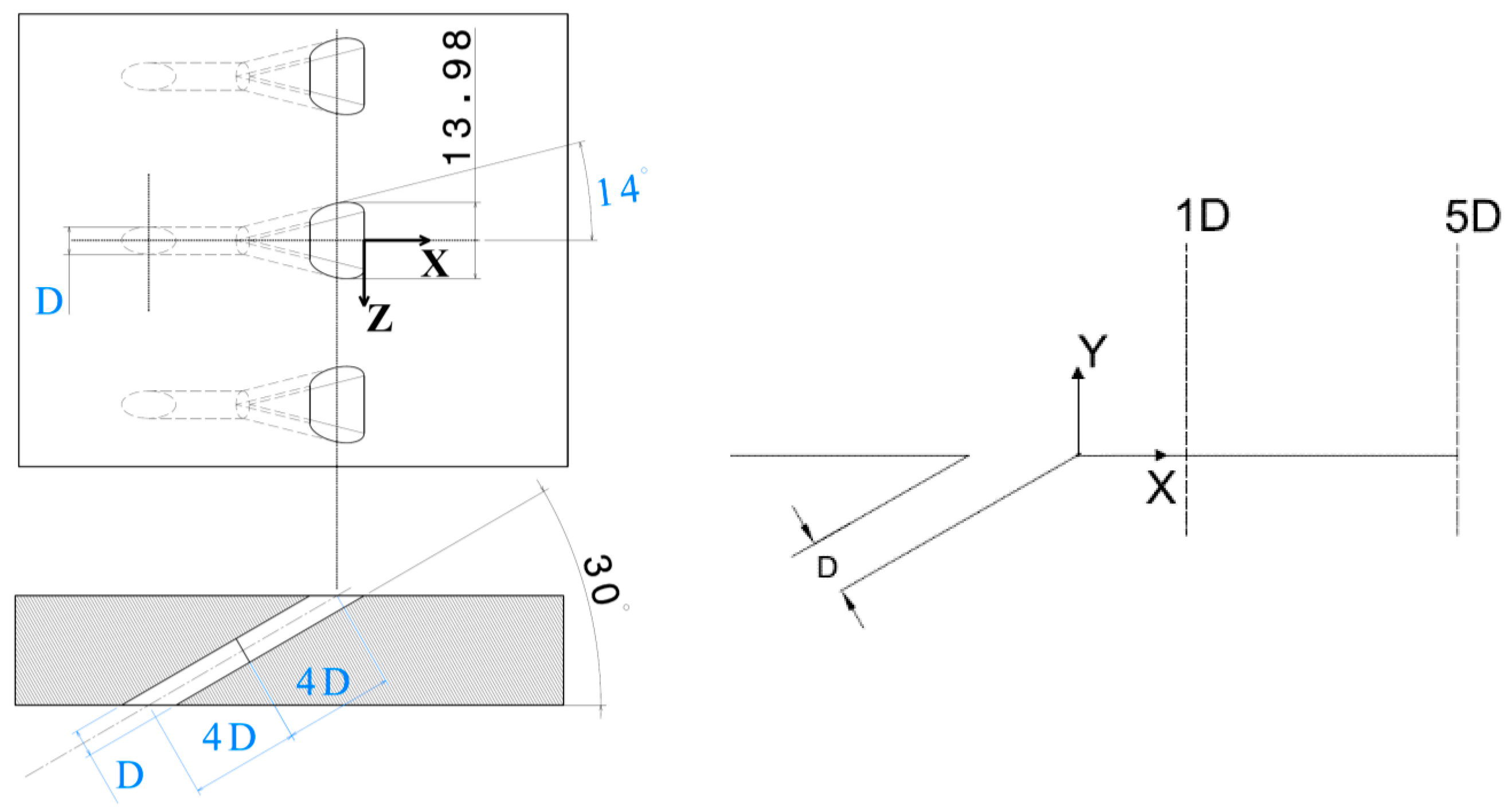
2. Experimental Set-Up

The low-speed flat plate wind tunnel available at the Energy Systems and Turbomachinery Laboratory of the University of Bergamo was used for this study. Tests have been carried out at low speed, about 15 m/s, and low inlet turbulence intensity level below 1.0%, for blowing ratio (BR) values of 1 and 2. A detailed description of both wind tunnel and test conditions is provided in [12]. The film cooling scheme consisted of a row of three fan-shaped holes with 5 mm diameter (Figure 1). Holes were sharp edge without using any fillets and inclined at 30° to the surface; pitch-to-diameter ratio was P/D = 6 and length to diameter ratio was L/D = 8. The lateral expansion angle of the fan-shaped hole was 14°, resulting in a hole width of 13.98 mm at the hole exit with t/P of 0.47 and a cross-sectional area ratio of 2.74. The chosen geometry of the fan-shaped hole was based on Gritsch et al. [2]. In addition, Table 1 reports the cross-sectional planes that have been selected for the experimental measurements and their positions according to the reference coordinate system shown in Figure 1 and Figure 2. It should be noted that origin of the reference coordinate system was located at the downstream edge of the middle hole (Z/D = 0).

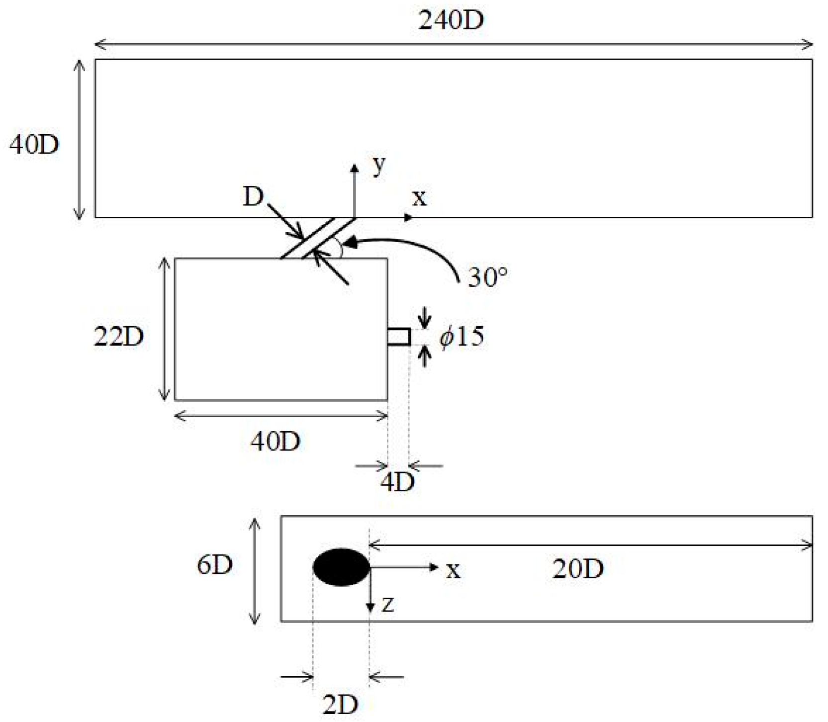
3. Computational Set-Up

3.1. Numerical Method and Boundary Conditions

RANS computations of a single jet injected through a fan-shaped hole into the mainstream were carried out at BR = 1 using the commercial CFD code, STAR-CCM+. Three different turbulence models, such as RKE, SST KW and RSM, were studied within the steady RANS approach. The working fluid was assumed to be incompressible air with temperature-dependent properties. Profiles of velocity and turbulence intensity, measured by the LDV technique, were applied at the inlet of the wind tunnel. The turbulent length scale for the mainstream was set to λ = 2.4 mm whereas, for the coolant, turbulence intensity (Tuc = 0.16·Rec−1/8) and length scale (λc = 0.07 Din) were determined from correlations of fully-developed pipe flow commonly used in CFD applications (see the user’s guide by ANSYS Fluent [13]). Atmospheric pressure was set at the outlet. Smooth wall, no-slip boundary conditions were applied to the tunnel walls. A mass flow boundary condition was applied at the plenum inlet: A coolant mass flow rate of 0.000957 kg/s corresponds to BR = 1. Temperature for the mainstream and coolant flow was set at 288 K and 323 K, respectively. The computational domain, as shown in Figure 2, includes the main test section, the cooling hole and the plenum. In the span-wise direction, the domain extends from one mid-pitch plane to another, containing a full injection hole. All the residuals were kept below 10−5. 1500 iterations were required to get convergence.

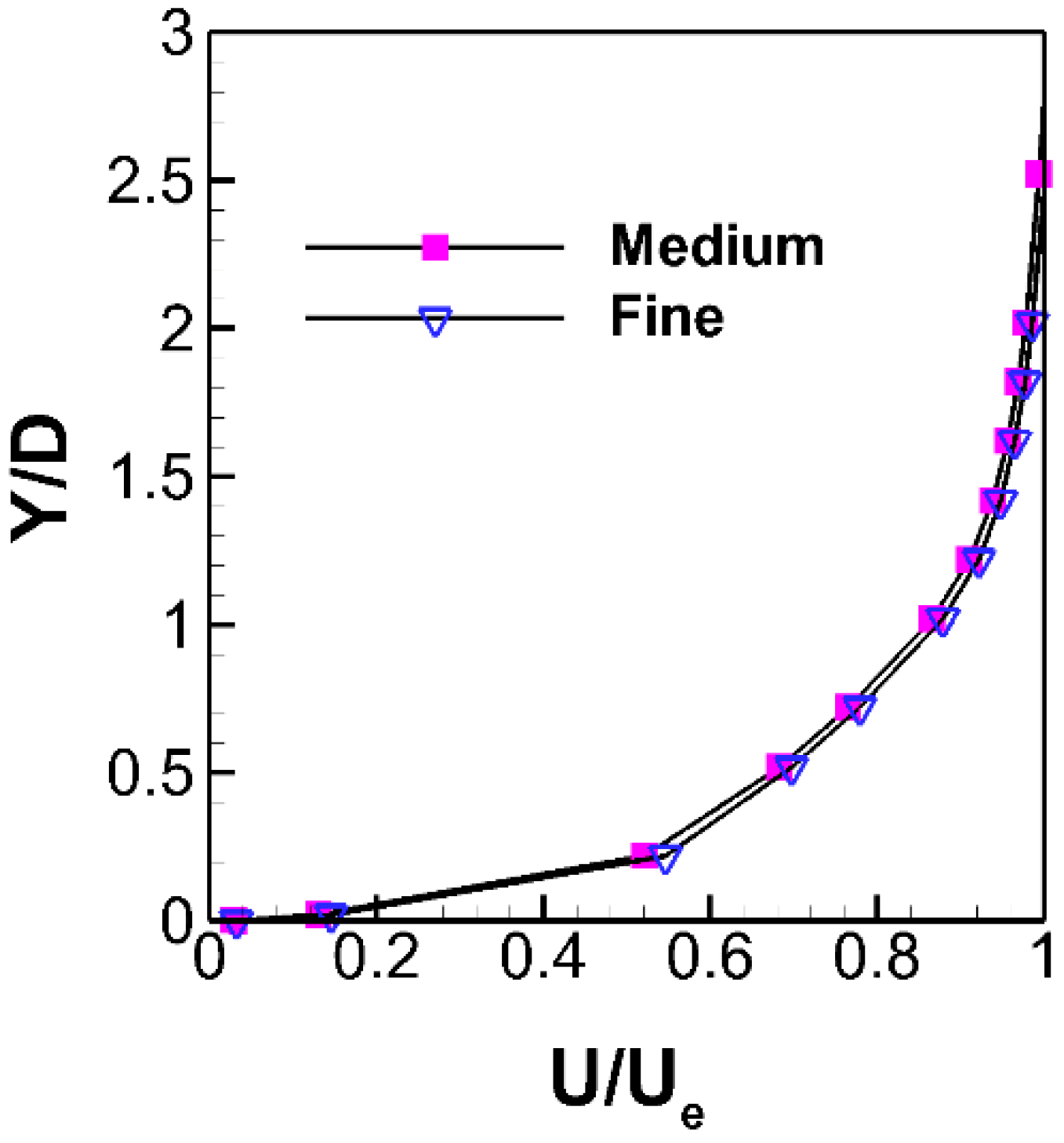
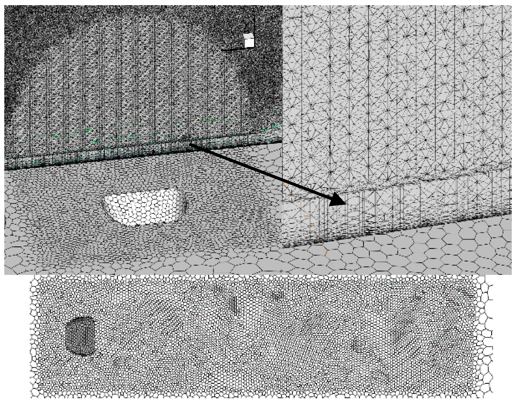
3.2. Computational Grid

The polyhedral mesh model was chosen in this study. The base mesh size was initially set to 0.03 m and refinement through the domain was controlled by growth parameters. Eight layers of prismatic cells were added near the wall, whose total height is 0.44D from the plate surface. Moreover, a cylindrical volumetric control was used to refine the mesh near the desired hole (Figure 3). Three grids were investigated for the sensitivity analysis, whose features are summarized in Table 2. Figure 4 compares the results from medium and fine grids, in terms of velocity profiles 5D downstream of injection holes, at BR = 1. Though the number of cells is quite different between these two grids, very good agreement is shown among the numerical velocity predictions. Accordingly, the medium grid was employed for all the RANS simulations. Since all turbulence models have been used with a two-layer zonal model for near-wall treatment, values of y+ were on the order of unity.

4. Experimental Results

Experimental results provided information regarding the aerodynamic and thermal behavior of the film cooling jet exiting three fan-shaped holes at blowing ratios of BR = 1 and 2. Aerodynamic investigations have been performed by means of laser doppler velocimetry (LDV), particle image velocimetry (PIV) and hot wire anemometer (HW) techniques. Concerning thermal measurements, the binary pressure sensitive paint (PSP) technique has been employed to measure adiabatic film cooling effectiveness.

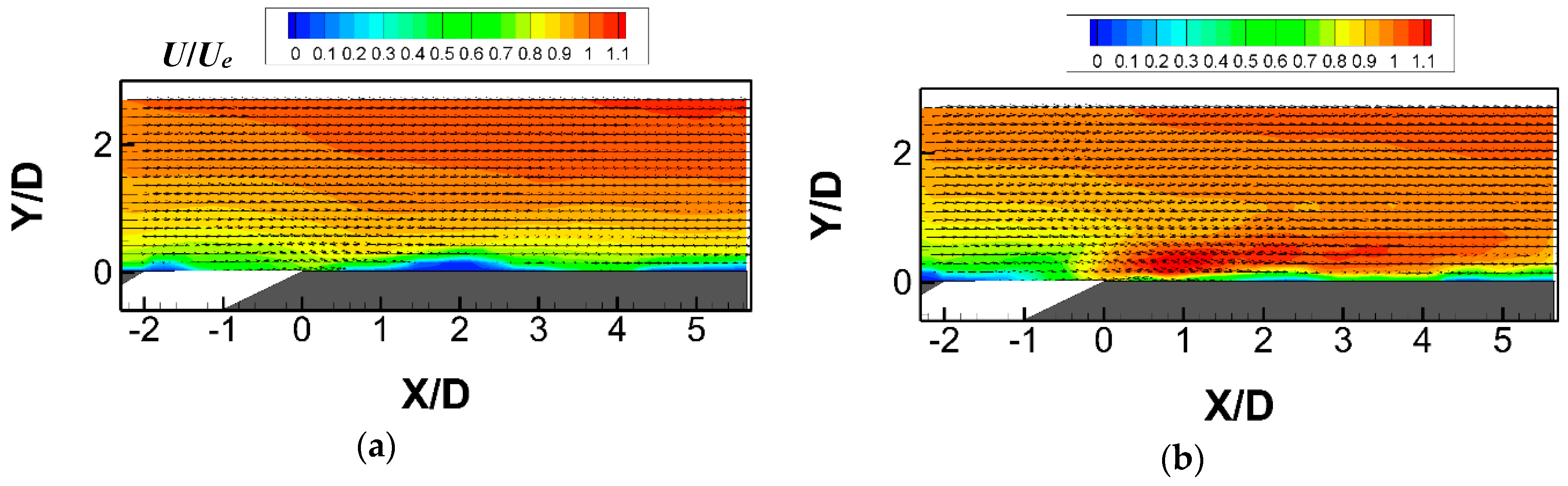
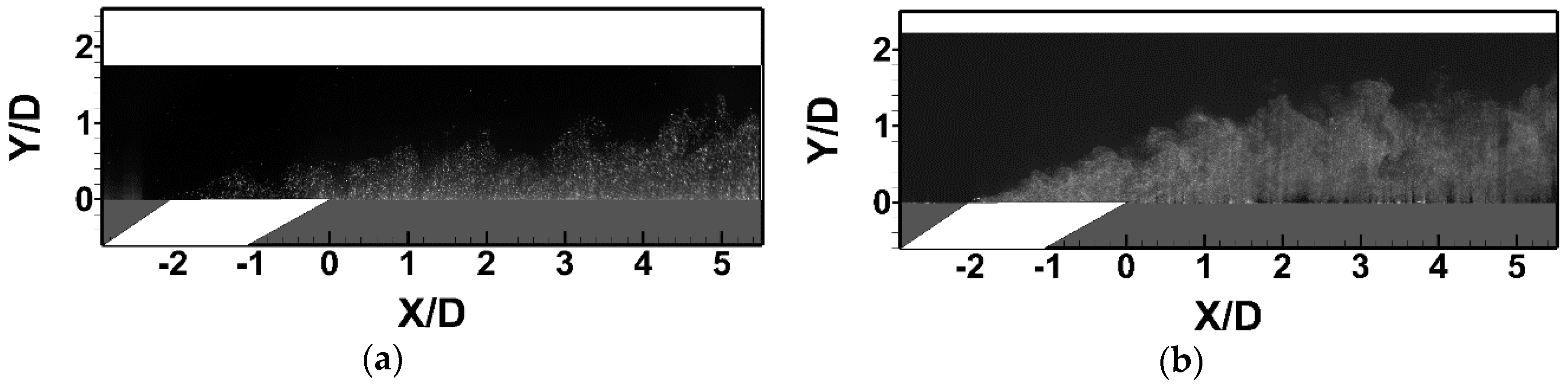
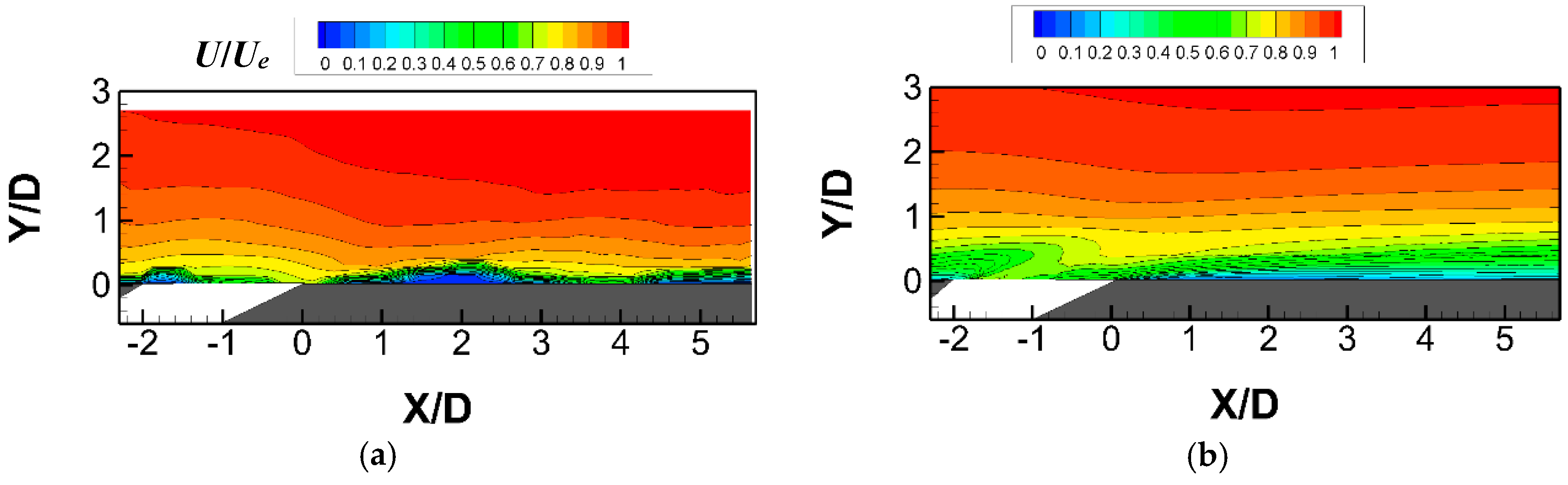
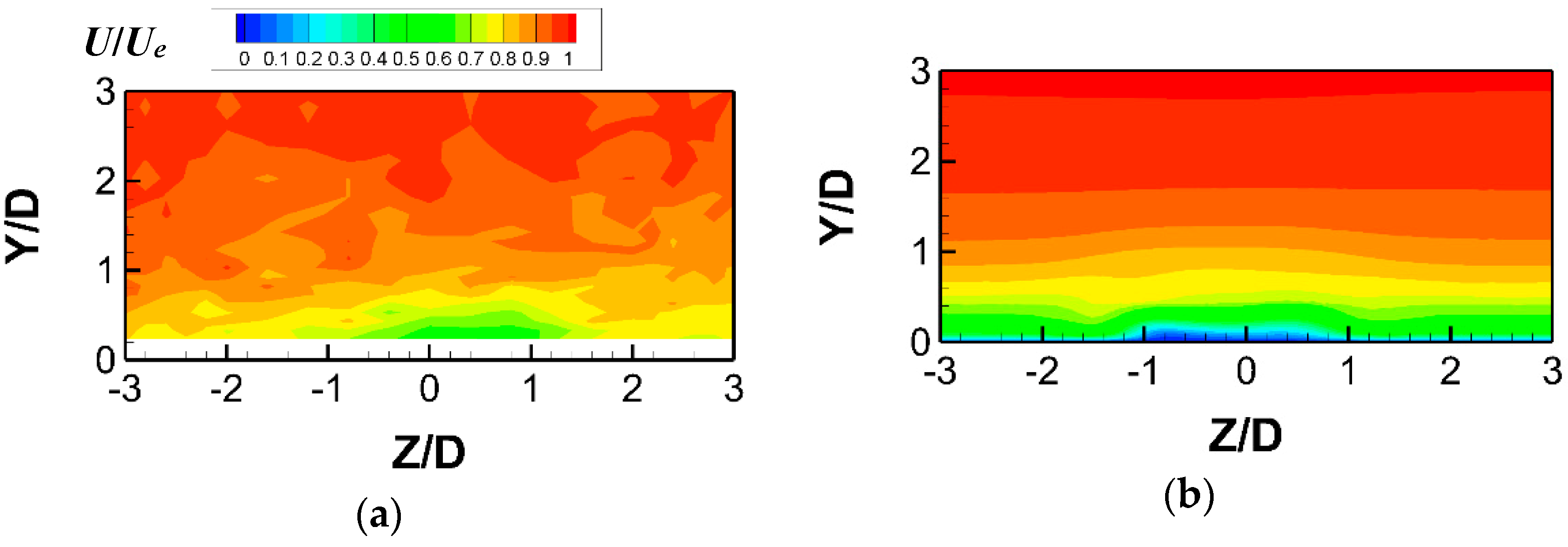
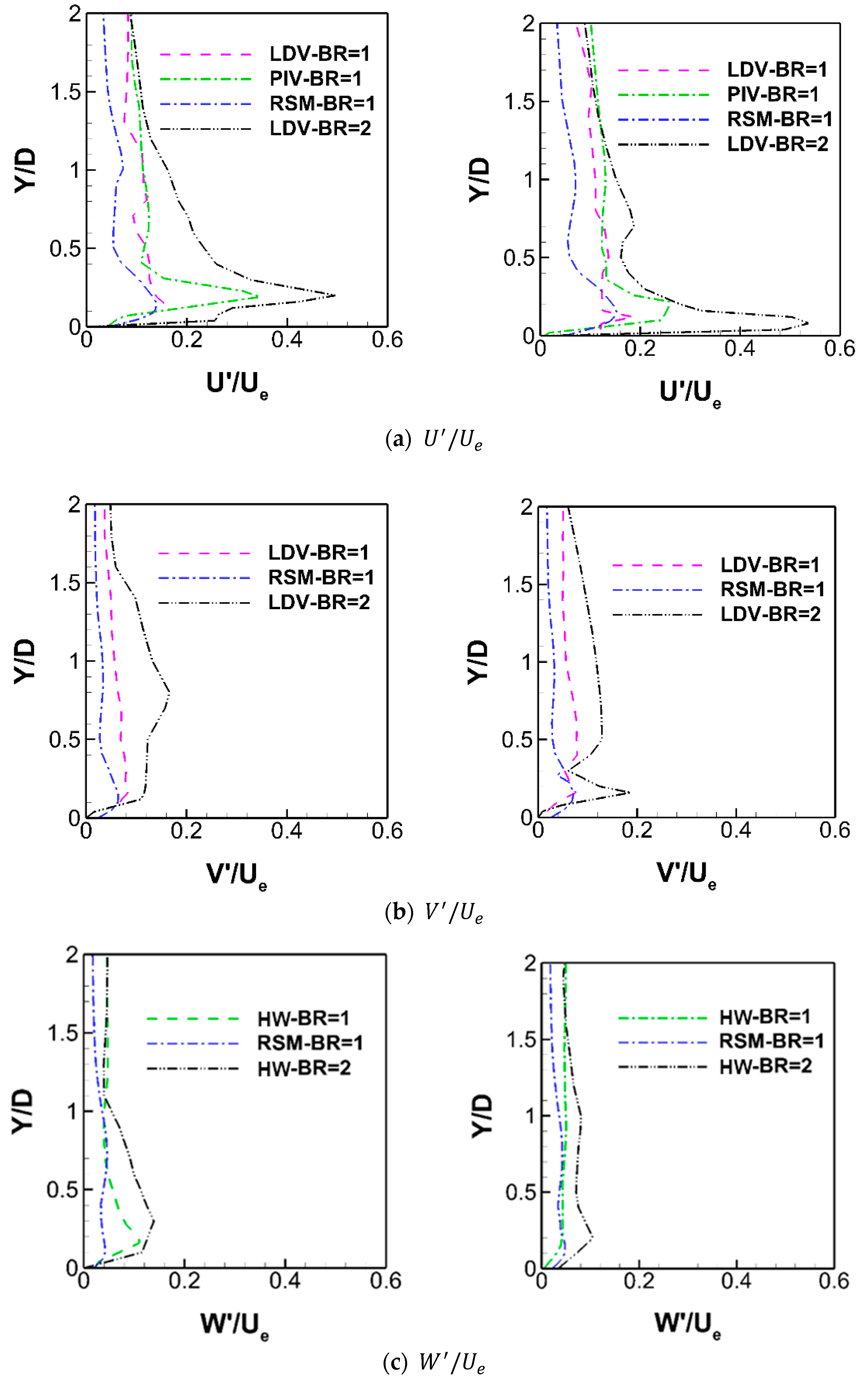
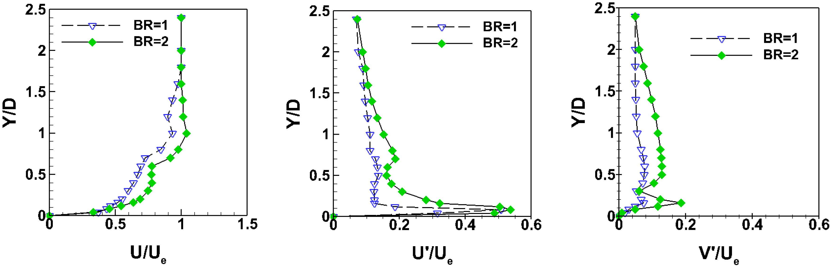
4.1. Aerodynamic Aspects of Film Cooling

The aerodynamic results start with the characterization of the injection condition through measuring the discharge coefficient. Figure 5 shows the Cd distribution versus the ratio of coolant pressure pt,c to the free stream static pressure, p. As pressure ratio increases, the flow entering the diffuser separates more and more from the diffuser wall, thus leading to a reduction in the pressure recovery as well as the discharge coefficient.
The next step consisted in measuring the boundary layer downstream of the mid-hole at hole centerline by means of the LDV technique. Details on LDV measurements are given in [12]. Results from LDV measurements at hole centerline are reported in Figure 6 and Figure 7 in terms of profiles of time-averaged streamwise velocity component as well as streamwise and wall normal rms velocities at X/D = 1 and = 5, respectively (Figure 1). Data were normalized with respect to the mainstream velocity Ue. There was no indication of a strong shear layer at the hole exit, for both BR. Also, the velocity profile was relatively flat downstream of the hole.
PIV technique (for more details refer again to Rouina et al. [12]) was used to characterize the mean and turbulent flow distribution over a stream-wise plane located at mid hole centerline (Z/D = 0). Normalized mean velocity flow fields in the near-hole region are shown in Figure 8, for BR of 1 and 2. It is evident that the coolant jet remained attached to the surface, in agreement with LDV results, even at the higher BR. It is worth mentioning that, increasing the BR to 2 did not lead to jet separation from the flat plate surface.
Flow visualizations (see again [12]) were also performed on the same plane to investigate the mixing process between the coolant and the mainstream (Figure 9). The unsteady nature of the jet interaction with the mainstream is documented by the presence of large coherent structures at the jet boundaries.

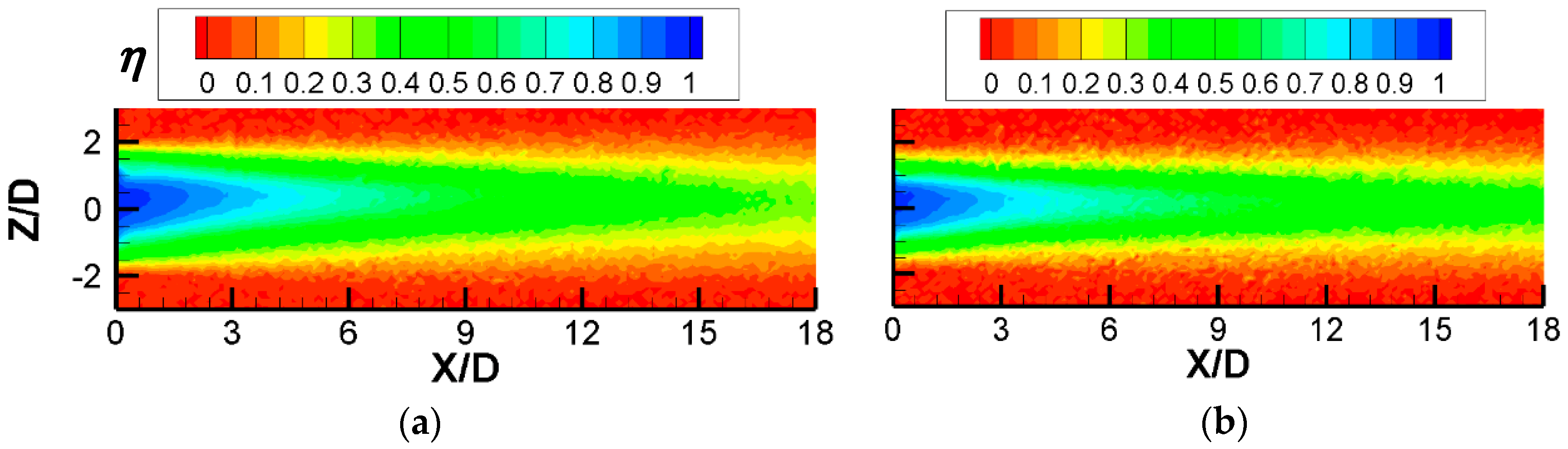
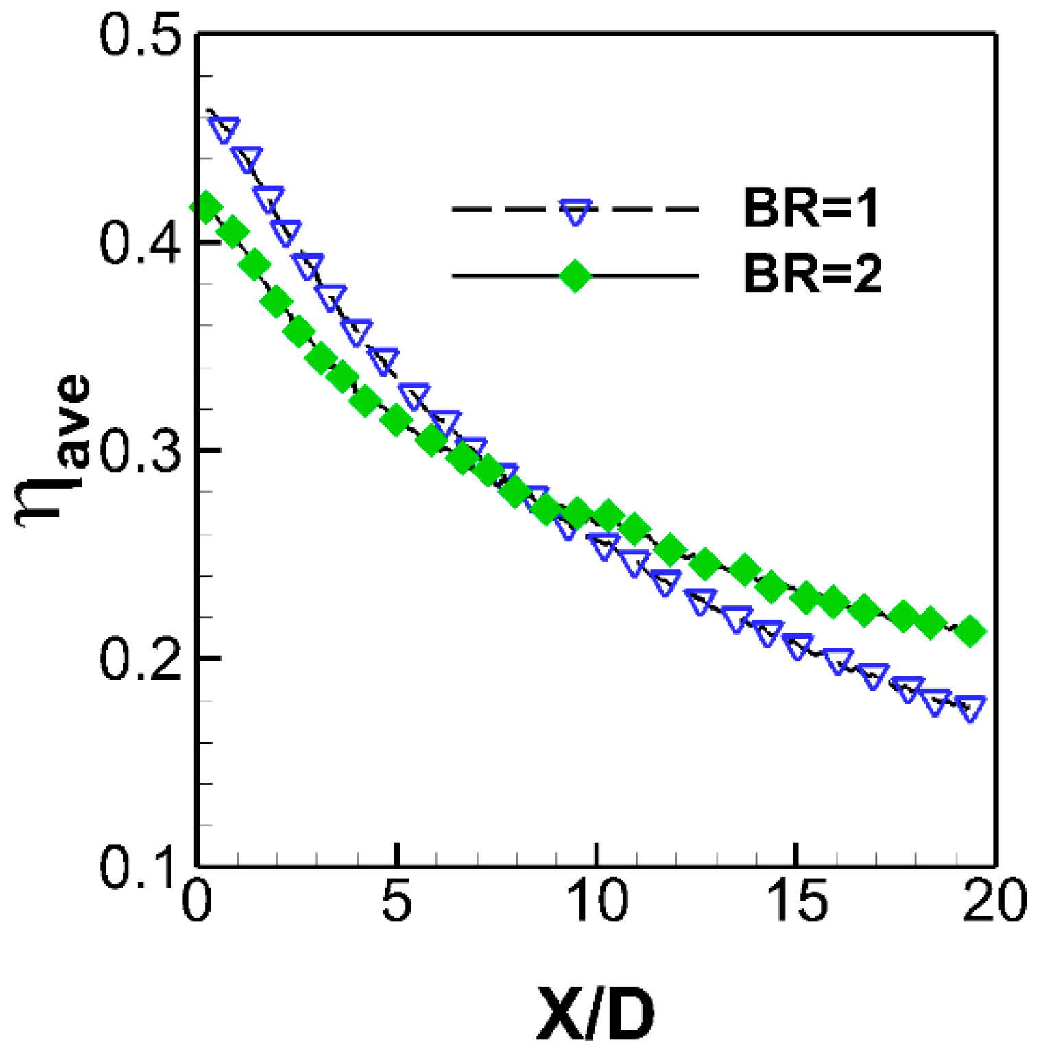
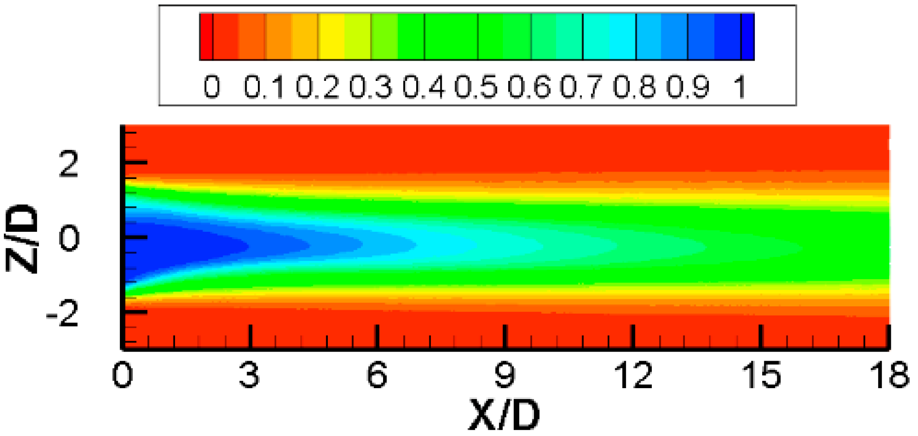
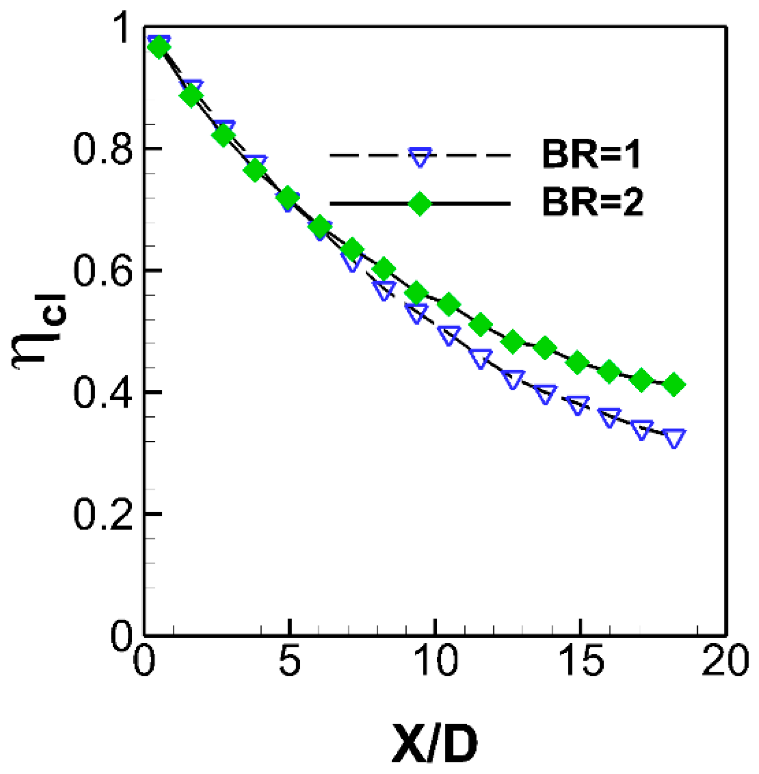
4.2. Thermal Aspects of Film Cooling

PSP technique was used to measure adiabatic film cooling effectiveness (η) on the surface of the flat plate (see Abdeh et al. [14]). Contours of η obtained by injecting nitrogen as the coolant stream, are depicted in Figure 10. For both BR, the jet is attached to the flat plate surface and spreads out laterally to ensure a more effective thermal protection compared to the cylindrical hole [12]. The centerline effectiveness, as a function of the distance from the hole, indicates that the fan-shaped hole provides values of ηcl > 0.7 within X/D < 5, for both BR (Figure 11). Conversely, the BR influences the ηcl decay at X/D > 7: The higher BR is more effective than the lower one at downstream locations. Figure 12 shows the laterally averaged film-cooling effectiveness (ηave) plotted versus the streamwise distance from the hole exit. Effectiveness decreases monotonously with the streamwise distance from the hole, for both BR, but with different slope. The highest ηave was found at BR = 1, in the near vicinity of the hole. Doubling the BR caused a slight reduction in ηave within X/D < 7, despite some minor improvements in ηave far from the hole exit.

5. Numerical Results

A preliminary RANS-based CFD study was conducted to validate and compare the above mentioned three turbulence models in order to determine the best option for predicting the film cooling jet behavior at BR = 1, i.e., the condition providing the highest effectiveness while minimizing the cooling air consumption.

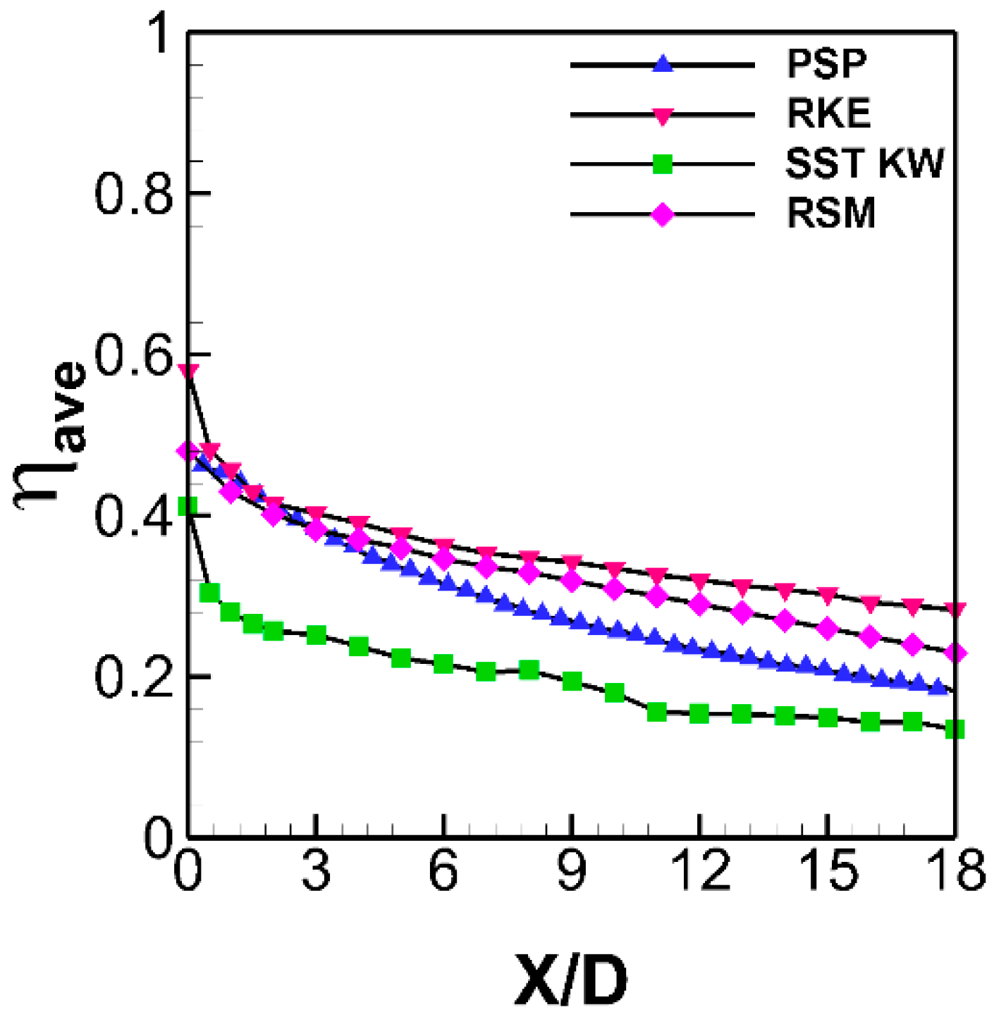
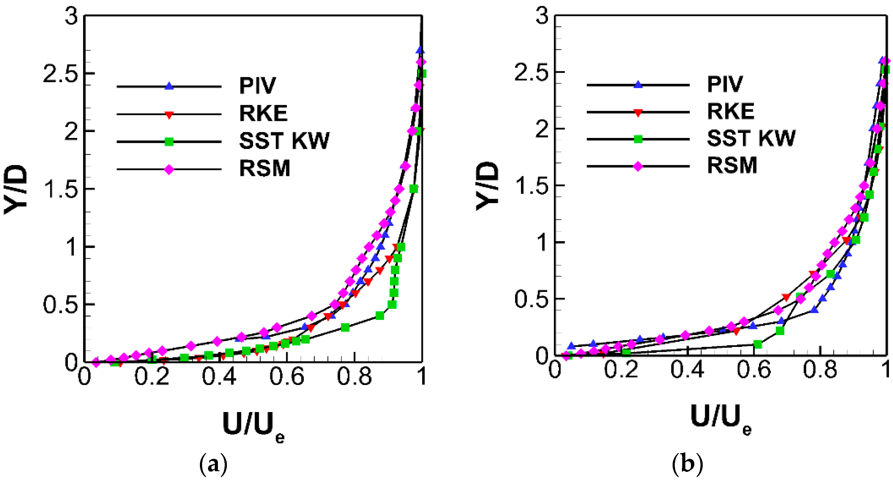
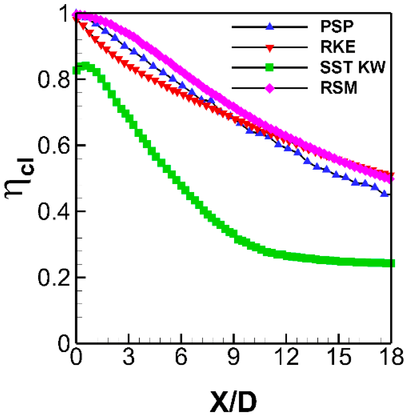
5.1. Turbulence Model Assessment

Laterally averaged and centerline film cooling effectiveness predicted by RKE, SST KW and RSM turbulence models were plotted and compared to PSP measurements in Figure 13 and Figure 14, respectively. The decreasing trend of film cooling effectiveness was best predicted by RSM and RKE. Surprisingly, results from the SST KW model were completely different from the experimental data as well as from the predictions by the other two models. This was due to SST KW tendency to overestimate separation of the cooling jet, thus leading to a narrower trace on the surface and, consequently, lower η. Figure 13 highlights that RSM predictions of ηave are the closest to PSP data: They are within 4% of measurements up to X/D = 4 whereas the deviation from the experimental data raises to about 15% at X/D = 18 (measured ηave = 0.195 against a predicted ηave = 0.225). Figure 14 shows that RSM slightly over-predicts ηcl while RKE under-predicts it, within X/D < 9. At X/D > 12, RKE and RSM profiles of ηcl collapse onto a single curve, thereby over-predicting the measured data.
Similarly, Figure 15 contains numerical profiles of the normalized streamwise velocity at 1D and 5D downstream of the holes for comparison against PIV measurements. RSM provides the most accurate prediction of U/Ue at 1D downstream of hole. Moving to X = 5D, although all three turbulence models predicted a steeper velocity profile compared to measurements, RSM and RKE results were anyhow reliable. Please note that flow separation occurred on the leeward side of the hole, according with RSM prediction. Considering both the reported thermal and aerodynamic aspects, one could conclude that the RSM is the most appropriate model to choose for fan-shaped holes in this set of experiments, thus minimizing the error in the prediction of ηave and U/Ue, at least in the near vicinity of the hole exit (X/D = 1).

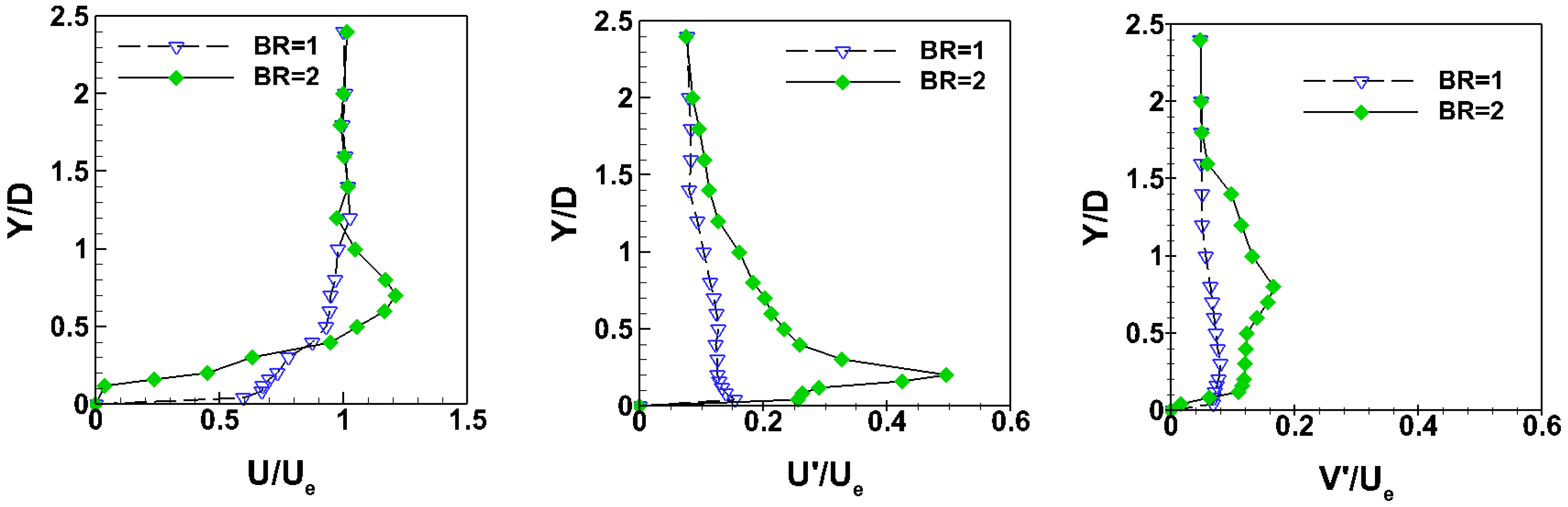
5.2. RSM Validation Against Experimental Data

Figure 16 presents the η contour predicted by RSM for validation against those shown in Figure 10a. Simulation results were in good agreement with the experimental one. The jet stays close to the surface according with the RSM model leading to high value of η in the near hole region, consistently with the PSP data. Considering the lateral spreading of coolant, the experimental pattern of η shows a slight narrowing of the coolant footprint on the surface, at increasing distance from the hole exit, whereas the RSM model provided a constant width coolant trace travelling in the stream wise direction. This indicates that lateral mixing was underestimated by RSM simulation, consistently with the above-mentioned profiles of ηave.
Special care was taken to assess the potential of RSM when dealing with off-the-wall features of the flow in the mixing region. 2D planes of normalized streamwise velocity flow field obtained from PIV measurements and RSM simulation are reported in Figure 17. Again, the measured velocity field matched well with RSM prediction. The same conclusion can be drawn looking at Figure 18 where the streamwise velocity in a vertical-lateral plane at 5D downstream of the hole is reported from both RSM and HW. However, it seems that RSM slightly overpredicts the vertical spreading of the jet when comparing to HW results, notwithstanding the impossibility of collecting measurements very close to the wall.
Computed and measured normalized stress profiles along the jet center plane (Z/D = 0) are shown in Figure 19 at X/D = 1 and X/D = 5, for BR = 1. On the one hand, RSM predicts the experimental trend of stress components accurately. On the other hand, it provides lower levels of streamwise stress components close to the wall than expected. Actually, the level of the normal stresses in the RSM model is controlled by their respective production terms, pressure-strain correlation terms and dissipation rate correlation. As documented by Hoda et al. [15], the failure of RSM to capture the experimental trends specifically in the wake of the jet is largely due to under predicted production levels.
Please also note that Figure 19 shows the experimental stress profiles at BR = 2, with the aim of assessing the influence of increasing BR on rms velocities. As expected, higher turbulent activity can be found inside the shear layer between the coolant and the mainstream when doubling the BR, with streamwise velocity fluctuations as large as 50% of the freestream velocity. A noteworthy degree of anisotropy is also evident, thus emphasizing the importance of using RSM.

6. Conclusions

The interaction between the mainstream and the film cooling jets exiting three fan-shaped holes has been investigated experimentally and numerically in terms of aerodynamic and thermal aspects, by using a flat plate wind tunnel. The operating conditions included low-speed and low inlet turbulence intensity, with BR equal to 1 and 2. Experimental investigations confirmed previous data available in the open literature regarding fan-shaped holes, i.e., the coolant jet stayed attached to the flat plate surface even at the higher BR of 2. Concerning numerical investigations, predictions from RKE, SST KW and RSM were compared against measurements of laterally and centerline adiabatic effectiveness, as well as off-the-wall velocity maps and profiles of stress components. RSM provided the most accurate predictions, considering both aerodynamic and thermal aspects of the coolant interaction with the mainstream. Solving individual components of the Reynolds stress tensor was rewarding to simulate the current set of experiments, as compared to the isotropic eddy viscosity assumption, while saving computational effort compared to scale resolving simulations.

Author Contributions

S.R. (Samaneh Rouina) performed the experimental tests, ran the CFD simulation and wrote most of the paper. S.R. (Silvia Ravelli) supervised the numerical activity. G.B. conceived the whole research and supervised the experimental activity.

Funding

This research received no external funding.

Conflicts of Interest

The authors declare no conflicts of interest.

Nomenclature

BRBlowing ratio
CdDischarge coefficient
DHole Diameter
LHole length
PPitch
Pressure
ReReynolds Number
TUTurbulence Intensity, %
U, V, WVelocity Components
U′, V′, W′RMS Velocity Components
ηFilm Cooling Effectiveness
λTurbulent Length Scale
Subscripts
aveLaterally averaged
cCoolant
clCenterline
eMainstream
inInlet
Abbreviations
CFDComputational Fluid Dynamic
LDVLaser Doppler Anemometry
PIVParticle Image Velocimetry
PSPPressure Sensitive Paint
RANSReynolds-averaged Navier-Stokes
RKERealizable k-ε model
RSMReynolds stress model
SST KWMenter SST k-ω

References

  1. Goldstein, R.J.; Eckert, E.R.G.; Burggraf, F. Effects of Hole Geometry and Density on Three Dimensional Film Cooling. Int. J. Heat Mass Transf. 1974, 17, 595–607. [Google Scholar] [CrossRef]
  2. Gritsch, M.; Schulz, A.; Wittig, S. Discharge Coefficient Measurements of Film-cooling Holes with Expanded Exits. J. Turbomach. 1998, 120, 557–563. [Google Scholar] [CrossRef]
  3. Gritsch, M.; Schulz, A.; Wittig, S. Film-cooling Holes with Expanded Exits: Near-Hole Heat Transfer Coefficients. Int. J. Heat Fluid Flow 2000, 21, 146–155. [Google Scholar] [CrossRef]
  4. Gritsch, M.; Colban, W.; Schar, H.; Dobbeling, K. Effect of Hole Geometry on the Thermal Performance of Fan-shaped Film Cooling Holes. ASME J. Turbomach. 2005, 127, 718–825. [Google Scholar] [CrossRef]
  5. Thole, K.; Gritsch, M.; Schulz, A.; Wittig, S. Flowfield Measurements for Film-Cooling Holes with Expanded Exits. ASME J. Turbomach. 1998, 120, 327–336. [Google Scholar] [CrossRef]
  6. Porter, J.; Sargison, J.; Walker, G.; Henderson, A. A Comparative Investigation of Round and Fan-Shaped Cooling Hole near Flow Fields. ASME J. Turbomach. 2008, 130, 041020. [Google Scholar] [CrossRef]
  7. Hyams, D.G.; Leylek, J.H. Detailed Analysis of Film Cooling Physics: PartIII-Streamwise Injection with Shaped Holes. ASME J. Turbomach. 2000, 122, 122–132. [Google Scholar] [CrossRef]
  8. Kohli, A.; Thole, K.A. A CFD investigation on the Effects of Entrance Crossflow Directions to Film Cooling Holes. In Paper Presented at the ASME Heat Transfer Division Meeting; ASME: New York, NY, USA, 1997; pp. 223–232. [Google Scholar]
  9. Silieti, M.; Kassab, A.J.; Divo, E. Film cooling effectiveness from a single scaled-up fan-shaped hole a CFD simulation of adiabatic and conjugate heat transfer models. In Proceedings of the ASME Turbo Expo 2005Power for Land, Sea, and Air, Reno-Tahoe, NV, USA, 6–9 June 2005. ASME Paper No. GT2005-68431. [Google Scholar] [CrossRef]
  10. Gustafsson, K.M.B.; Johansson, T.G. Numerical Simulation of Effusion Cooling with Comparison to Experimental Data. Prog. Comput. Fluid Dyn. 2006, 6, 101–109. [Google Scholar] [CrossRef]
  11. Javadi, A.; Javadi, K.; Taeibi-Rahni, M.; Keimasi, M.R. Reynold’s Stress Turbulence Models for Prediction of Shear Stress terms in Cross Flow Film Cooling Numerical Simulation. In Proceedings of the ASME 2002 Pressure Vessels and Piping Conference, Vancouver, BC, Canada, 5–9 August 2000; Volume 2, pp. 155–167. [Google Scholar]
  12. Rouina, S.; Miranda, M.; Barigozzi, G. Experimental Investigation of the Unsteady Flow Behavior on a Film Cooling Flat Plate. Energy Procedia 2016, 101, 726–733. [Google Scholar] [CrossRef]
  13. ANSYS FLUENT 16.0 User’s Guide; ANSYS, Inc.: Canonsburg, PA, USA, 2015.
  14. Abdeh, H.; Miranda, M.; Rouina, S.; Barigozzi, G. Development of PSP technique for Vane Film Cooling Investigations. Energy Procedia 2017, 126, 802–809. [Google Scholar] [CrossRef]
  15. Hoda, A.; Acharya, S.; Tyagi, M. Reynolds Stress Transport Model Predictions and Large Eddy Simulation for Film Coolant Jet in Cross Flow. In Proceedings of the ASME TURBOEXPO 2000, Munich, Germany, 8–11 May 2000. ASME Paper No. 2000-GT-0249. [Google Scholar] [CrossRef]
Figure 1. Schematic of flat plate.
Ijtpp 04 00007 g001
Figure 2. Computational domain.
Ijtpp 04 00007 g002
Figure 3. Prism layers and near wall mesh refinement through cylindrical volumetric control.
Ijtpp 04 00007 g003
Figure 4. Comparison of normalized streamwise velocity profiles at X = 5D (realizable k-ε (RKE) model).
Ijtpp 04 00007 g004
Figure 5. Hole discharge coefficient.
Ijtpp 04 00007 g005
Figure 6. Boundary layer profiles at X/D = 1.
Ijtpp 04 00007 g006
Figure 7. Boundary layer profiles at X/D = 5.
Ijtpp 04 00007 g007
Figure 8. Flow velocity field at Z/D = 0: (a) Blowing ratio (BR) = 1; (b) BR = 2.0.
Ijtpp 04 00007 g008
Figure 9. Flow visualization at Z/D = 0: (a) BR = 1; (b) BR = 2.0.
Ijtpp 04 00007 g009
Figure 10. Adiabatic film cooling effectiveness contours: (a) BR = 1; (b) BR = 2.0.
Ijtpp 04 00007 g010
Figure 11. Centerline film cooling effectiveness profiles—experimental results.
Ijtpp 04 00007 g011
Figure 12. Laterally averaged film cooling effectiveness profiles—experimental results.
Ijtpp 04 00007 g012
Figure 13. Laterally-averaged effectiveness: comparison between CFD predictions and experimental result (BR = 1).
Ijtpp 04 00007 g013
Figure 14. Centerline effectiveness: Comparison between CFD predictions and experimental results (BR = 1).
Ijtpp 04 00007 g014
Figure 15. Normalized streamwise velocity: Comparison between CFD predictions and experimental result (BR = 1), (a) X = 1D; (b) X = 5D.
Ijtpp 04 00007 g015
Figure 16. Film cooling effectiveness contour predicted by Reynolds stress module (RSM) (BR = 1).
Ijtpp 04 00007 g016
Figure 17. Normalized streamwise velocity contours—comparison of CFD prediction with experimental data (BR = 1, Z/D = 0): (a) Particle image velocimetry (PIV) and (b) RSM.
Ijtpp 04 00007 g017
Figure 18. Normalized streamwise velocity contours—comparison of CFD prediction with experimental data in span-wise plane (BR = 1, X/D = 5): (a) Hot wire (HW) and (b) RSM.
Ijtpp 04 00007 g018
Figure 19. Comparison of stress profiles with experimental data at X/D = 1 (left) and X/D = 5 (right), Z/D = 0, BR = 1, and BR = 2.
Ijtpp 04 00007 g019
Table 1. Measurement plane positions.
Measurement TechniquePlane
PIV flow visualizationXY
PIV measurementXY
HotwireYZ
PSPXZ
Table 2. Grid sensitivity.
GridBase Size (m)Volumetric Control Grid Size (m)y+Cells Count
Coarse0.030.001<55,785,194
Medium0.020.001<16,785,194
Fine0.020.001<110,920,371

