Article

Parametric Study of a Turbofan Engine with an Auxiliary High-Pressure Bypass

by
Sharanabasaweshwara A. Asundi
* and
Syed Firasat Ali
Aerospace Science Engineering, Tuskegee University, Tuskegee, AL 36088, USA
*
Author to whom correspondence should be addressed.
Int. J. Turbomach. Propuls. Power 2019, 4(1), 2; https://doi.org/10.3390/ijtpp4010002
Submission received: 20 July 2018 / Revised: 20 December 2018 / Accepted: 7 January 2019 / Published: 14 January 2019

Abstract

:
A parametric study of a novel turbofan engine with an auxiliary high-pressure bypass (AHPB) is presented. The underlying motivation for the study was to introduce and explore a configuration of a turbofan engine which could facilitate clean secondary burning of fuel at a higher temperature than conventionally realized. The study was also motivated by the developments in engineering materials for high-temperature applications and the potential utility of these developments. The parametric study is presented in two phases. Phase I presents a schematic of the turbofan engine with AHPB and the mathematics of the performance parameters at various stations. The proposed engine is hypothesized to consist of three streams—core stream, low-pressure bypass (LPB) stream, and the AHPB or, simply, the high-pressure bypass (HPB) stream. Phase II delves into the performance simulation and the analysis of the results in an ideal set-up. The simulation and results are presented for performance analysis when (i) maximizing engine thrust while varying the LPB and AHPB ratios, and (ii) varying the AHPB ratio while maintaining the LPB ratio constant. The results demonstrate the variations in performance of the engine and a basis for examining its potential utility for practical applications.

1. Background and Introduction

A turbofan engine of an airplane has a single inlet that splits into a core stream and a bypass stream. In a separate-exhaust turbofan engine, the two streams exit through separate exhaust nozzles [1]. In a mixed-exhaust turbofan engine, the fan stream joins the core stream, and exhausts through a single nozzle [1]. Significant research was published on techniques of introducing a secondary burner in addition to the core/main combustion/burning. The afterburner is the most widely used secondary combustion in industry and is described in several references. Reference [2] states, “currently engines are limited to turbine temperatures of about 2000–2500 °F (1093–1371 °C), which requires an air/fuel mixture of about 60 to 1. However, only about a quarter of the compressed air is actually used for combustion. If fuel is injected into this largely uncombusted hot air, it will mix, burn, and increase the thrust by as much as a factor of two. Unfortunately, such “afterburning” is inefficient in terms of fuel usage because the burning is done at a lower pressure and the oxygen is partially depleted”. Similarly, Reference [1] states, “the dual-spool, mixed-flow, augmented, low-bypass turbofan is the engine cycle of choice for all modern high-performance fighter aircraft and supersonic bombers”. In Reference [3], the authors discuss an inter-turbine burner as a second burner and suggest further examination of their proposed constant-volume burning. In Reference [4], the authors state, “an engine with an extra combustor installed between the turbine stages will be referred to as a two-combustor engine: the additional combustor will be designated as an inter-stage turbine burner”. They used constant-pressure burning and concluded that the increase in specific thrust might be noteworthy, particularly for fighter-jet applications. In Reference [5], the authors proposed that combustion be continued inside the turbine to increase the efficiency and specific thrust of the engine. Their analysis showed an increase in specific thrust and a decrease in thrust-specific fuel consumption (TSFC).
This paper presents a study and a design-point analysis of a novel turbofan engine with an auxiliary high-pressure bypass. The proposed engine has one inlet and three separate flow streams exiting through separate exhaust nozzles. The low-pressure bypass (LPB) stream goes through a fan and a nozzle. The compressor is common for the core and auxiliary high-pressure bypass (AHPB) streams. An annulus at the compressor exit guides its peripheral flow to form the AHPB stream, which goes through a burner and a nozzle for its exhaust. The core stream from the compressor goes through the core burner, the turbine, and the core exhaust nozzle. The study compares the performance parameters for different sets of values of the two bypass ratios, AHPB and LPB. For the core stream, the highest total temperature is usually much less than its theoretically estimated value for efficient performance of the engine, because it is limited by the material and the design features of the turbine blades. The AHPB stream has a separate burner and it does not pass through the turbine; therefore, its total temperature may be raised to a higher value than that of the core stream. Considering that the flow at the exit of AHPB burner goes through the exhaust nozzle without passing through the turbine blades, the AHPB nozzle design would significantly benefit from advances in the development of ceramic materials for high-temperature applications [6]. In contrast to the afterburner, the AHPB burner presented in this article merits consideration due to its burning in air directly from the compressor (high total pressure) without depletion of oxygen. Last but not least, the AHPB provision may better facilitate the design and realization of hybrid electric aircraft, which are being researched and developed aggressively [7]. An AHPB stream comparable to the size of an LPB stream may be driven by an electrical actuator and power source, thereby reducing the burden on the turbine to drive the compressor and fan of a turbofan engine.

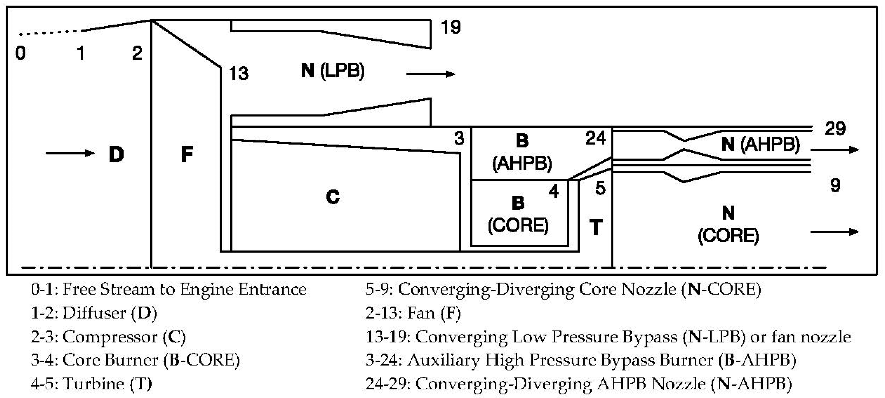
2. Configuration of the Turbofan Engine with an Auxiliary High-Pressure Bypass

A conceptual configuration of the turbofan engine with AHPB is shown in Figure 1. As shown in this figure, the engine has separate exhaust nozzles for the three different streams—(i) core stream, (ii) LPB stream, and (iii) AHPB stream. The air flow from the fan forms the LPB stream, which exhausts through the LPB nozzle. The air flow from the compressor divides into two streams, where (i) the flow through the peripheral segment of the compressor forms the AHPB stream, and (ii) the flow from the inner segment of the compressor forms the core stream. The core stream goes through the core burner, the turbine, and the core nozzle on its way to the exhaust. The AHPB stream, which is the novel feature, goes through the AHPB burner and AHPB nozzle for its exhaust. The core and AHPB burners receive flows of fuel that are separately controlled during the flight. The turbine powers the compressor and the fan.

3. Formulation of the Performance Parameters of the Turbofan Engine with an Auxiliary High-Pressure Bypass

This section presents the formulation of performance parameters for stations identified in Figure 1. The flows assumed for an engine powering an airplane in subsonic flight in standard atmosphere were as follows:
  • Isentropic flows without work are assumed through the diffuser and nozzles;
  • Isentropic flows with work are assumed through the compressor, fan, and turbine;
  • Constant-total-pressure flows are assumed in the core burner and AHPB burner;
  • The core stream and AHPB stream exhaust through converging–diverging nozzles;
  • The LPB stream exhausts through a converging nozzle.
The AHPB stream was introduced with the goal to burn fuel at a relatively higher temperature as compared to the core or LPB stream. To accommodate this feature, a converging–diverging or a perfectly expanded nozzle was assumed. For comparable performance, a similar nozzle was assumed for the core stream.

3.1. Performance Parameters for Free Stream and Diffuser

The total temperature, T t 0 , total pressure, p t 0 , and total specific enthalpy, h t 0 , were computed by substituting i = 0 into Equations (1)–(3), respectively, and taking γ = γ 0 . The subscript “t” denotes total values.
T t i T i = 1 + ( γ 1 ) 2 M i 2 ;
p t i p i = ( T t i T i ) γ γ 1 ;
h t i = C p T t i .
Here, isentropic flow without work is assumed from stations 0 through 2 (i.e., p t 2 = p t 1 = p t 0 and h t 2 = h t 1 = h t 0 ). For completeness, the speed of sound, a 0 , and the velocity of air at the entrance, V 0 , were computed by substituting i = 0, taking γ = γ 0 , and R = R 0 into Equations (4) and (5), respectively.
a i = γ R T i ;
V i = M i a i .

3.2. Performance Parameters for Compressor, Core Burner, Fan, and Auxiliary High-Pressure Bypass Burner

As a limiting factor, the total temperature of the core burner exit, which is also the turbine entrance, was taken to be 1625 K (i.e., T t 4 = 1625   K ) and the AHPB burner exit was taken to be 1950 K (i.e., T t 24 = 1950   K ).
(a)
Core stream—The compressor total pressure ratio was taken to be 50, ( π c = 50 ) and constant-total-pressure combustion was assumed, i.e., p t 4 = p t 3 . Based on these, the core stream values (Tt3, ht3, and ht4) were computed. The stagnation value of temperature, Tt3, was computed by substituting i = 2 and j = 3 into Equation (6).
T t j T t i = ( p t j p t i ) γ 1 γ .
The total specific enthalpies, h t 3 and h t 4 , were computed by substituting i = 3 and i = 4, respectively, into Equation (3), and taking C p = C p 4 .
(b)
LPB stream—With the intent of obtaining maximum thrust and maximizing the overall efficiency [1], the fan total pressure ratio, π F = p t 13 p t 2 , was varied between 1.78 and 6.10 for the LPB ratio varying from α L P B = 0 through α L P B = 12 . Also, p t 19 = p t 13 . The stagnation value of temperature, T t 13 , was computed by substituting i = 2, j = 13, and γ = γ 0 into Equation (6). The stagnation value of specific enthalpy, h t 13 , was computed by substituting i = 13 into Equation (3). Additionally, T t 19 = T t 13 and h t 19 = h t 13 .
(c)
AHPB stream—The stagnation value of specific enthalpy, h t 24 , was computed by substituting i = 24 and C p = C p 24 into Equation (3). Additionally, T t 29 = T t 24 and h t 29 = h t 24 .

3.3. Power Inputs and Outputs

The energy rate balance equations, Equations (7) and (8), were used to compute the mass flow rates of the fuel in the core burner and the AHPB burner, respectively.
m ˙ 0 h t 3 + m ˙ f Q R = ( m ˙ 0 + m ˙ f ) h t 4 ;
α A H P B m ˙ 0 h t 3 + m ˙ f A H P B Q R = ( α A H P B m ˙ 0 + m ˙ f A H P B ) h t 24 .
The thermal power input, compressor power, fan power, and turbine power were computed as follows:
Thermal   power   input   =   ( m ˙ f + m ˙ f A H P B ) Q R ;
Compressor   ( core   and   AHPB )   power   =   ( m ˙ 0 + m ˙ A H P B ) ( h t 3 h t 2 ) ;
Fan   power   = α L P B m ˙ 0 ( h t 13 h t 2 ) ;
Turbine power = compressor power + fan power.
Then, the stagnation value of specific enthalpy, h t 5 , was computed from the turbine power equation, i.e., P t u r b = ( m ˙ 0 + m ˙ f ) ( h t 5 h t 4 ) . The stagnation value of temperature, T t 5 , was computed by substituting i = 5 into Equation (3) and taking C p = C p 4 . Additionally, h t 9 = h t 5 .

3.4. Velocities and Mass Flow Rates

The velocities and mass flow rates were computed at the nozzle exit of the three streams.
(a)
Core stream—The total pressure at station 5, p t 5 , was computed by substituting i = 4 and j = 5 into Equation (6), and taking γ = γ 4 . It was also assumed that station 5 to station 9 was a perfectly expanded converging–diverging nozzle, i.e., p 9 = p 0 . Additionally, p t 9 = p t 5 as the flow was assumed to be isentropic. The temperature at the nozzle exit, T 9 , was computed by substituting i = 9 into Equation (2) and taking γ = γ 4 . The Mach number ( M 9 ), the speed of sound ( a 9 ), and the velocity of air ( V 9 ) were computed using Equations (9)–(11). Since a perfectly expanded converging–diverging nozzle was assumed, V 9 e f f = V 9 .
T t 9 = 1 + 0.5 ( γ 4 1 ) M 9 2 ;
a 9 = γ 4 R 4 T 9 ;
V 9 = M 9 a 9 .
(b)
Low-pressure bypass stream—It is to be noted that station 13 to station 19 was assumed to be a converging nozzle, i.e., M19 ≤ 1 (not perfectly expanded). Initially, M 19 was computed with the assumption that p 19 = p 0 . However, if M19 ≥ 1, then M19 = 1; if not (i.e., M19 < 1), then M19 is taken to be the same as the computed value. At the LPB nozzle exit, the Mach number (M19), the speed of sound (a19), and the velocity of air (V19) were computed similarly to that in the core stream. Here, V 19 e f f was computed as
V 19 e f f = V 19 + a 19 2 γ 0 V 19 ( 1 p 0 p 19 ) .
(c)
AHPB stream—For the AHPB stream, station 24 to station 29 was assumed to be a perfectly expanded converging–diverging nozzle, i.e., p 29 = p 0 . Additionally, p t 29 = p t 24 , as the flow was assumed to be isentropic. The temperature at the nozzle exit, T 29 , was computed by substituting i = 29 into Equation (2) and taking γ = γ 24 . At the AHPB nozzle exit, the Mach number (M29), the speed of sound (a29), and the velocity of air (V29) were also computed similarly to the corresponding values in the core stream. Since a perfectly expanded converging–diverging nozzle was assumed, V 29 e f f = V 29 .

3.5. Thrusts, Fuel Consumption, and Efficiencies

Finally, the following parameters were computed for various bypass ratios to evaluate the performance of the proposed new configuration of the engine:
  • Thrust of the various streams—core thrust, LPB thrust, AHPB thrust, and total thrust.
    Core ,   net   thrust ,   F c o r e = ( m ˙ 0 + m ˙ f c o r e ) V 9 e f f m ˙ 0 V 0 ;
    LPB ,   net   thrust ,   F L P B = α L P B m ˙ 0 V 19 e f f α L P B m ˙ 0 V 0 ;
    AHPB ,   net   thrust ,   F A H P B = ( α A H P B m ˙ 0 + m ˙ f A H P B ) V 29 e f f α A H P B m ˙ 0 V 0 ;
    Total   ( net )   engine   thrust ,   F t o t a l = F c o r e + F L P B + F A H P B
  • Thrust-specific fuel consumption (TSFC)
    T S F C = m ˙ f c o r e + m ˙ f A H P B F t o t a l .
  • Total specific thrust—specific thrust of the core, LPB stream, AHPB stream
    Total   specific   thrust = F t o t a l ( 1 + α L P B + α A H P B ) m ˙ 0
  • Rate of kinetic energy difference for the various streams
    Rate   of   kinetic   energy   ( KE )   difference   at   the   core   = 1 2 ( m ˙ 0 + m ˙ f c o r e ) V 2 9 e f f 1 2 m ˙ 0 V 0 2 ;
    Rate   of   KE   difference   at   the   LPB   stream = 1 2 α L P B m ˙ 0 V 2 19 e f f 1 2 α L P B m ˙ 0 V 0 2 ;
    Rate   of   KE   difference   at   the   AHPB   stream = 1 2 ( α A H P B m ˙ 0 + m ˙ f A H P B ) V 2 29 e f f 1 2 α A H P B m ˙ 0 V 0 2 ;
    Total rate of KE difference = sum of the rates of KE differences for the core, LPB, and AHPB streams.
  • Efficiencies—thermal efficiency, propulsive efficiency, and overall efficiency
    Thermal   efficiency , η t h = total   rate   of   KE   difference ( m ˙ f c o r e + m ˙ f A H P B ) Q R ;
    Propulsive   efficiency ,   η p = ( total   engine   thrust ) V 0 total   rate   of   KE   difference ;
    Overall   efficiency , η o = η t h η p .

4. Simulation and Results

To comprehensively evaluate the turbofan engine with AHPB, simulations were performed, and results were analyzed for the following scenarios: (i) maximizing engine thrust while varying LPB and AHPB ratios, and (ii) constant LPB ratio with varying AHPB ratios. A computer program was developed to compute and plot performance parameters of the turbofan engine with AHPB as a function of varying LPB and AHPB ratios. The simulation parameters and properties, representing a typical commercial transport airplane cruising at high subsonic velocity, are captured in Table 1.

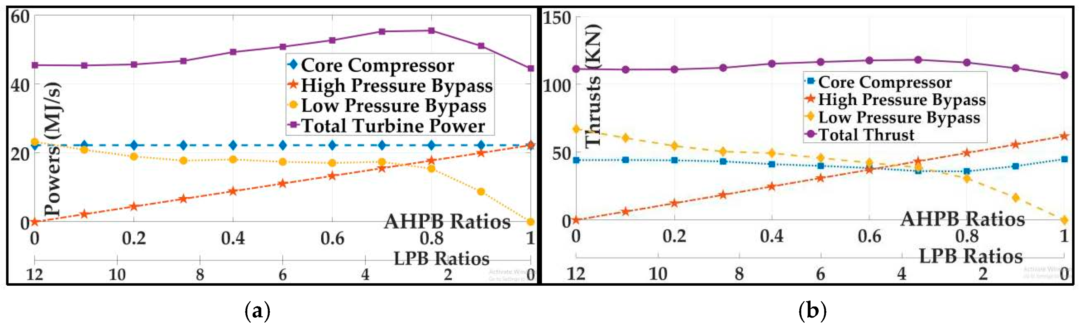
4.1. Varying Low-Pressure Bypass and Auxiliary High-Pressure Bypass Ratios for Maximizing Thrust and Overall Efficiency

In this scenario, the core stream mass flow rates ( m ˙ 0 and m ˙ f o r c e ) were maintained as constants, while the LPB and AHPB ratios, i.e., α L P B and α A H P B , were varied to showcase various configurations of the proposed turbofan engine with AHPB. Figure 2 shows 11 configurations of the turbofan engine with AHPB, where the LPB ratio varied from 12 to 0 in increments of 1.2, and AHPB ratio varied from 0 to 1 in increments of 0.1. For a turbofan engine with an LPB ratio of 6, i.e., α L P B = 6 , and an AHPB ratio of 0.5, i.e., α A H P B = 0.5 , if the core stream air mass flow rate is 40 kg/s, i.e., m ˙ 0 = 40 kg / s , the AHPB and LPB air mass flow rates are 20 kg/s and 240 kg/s, respectively ( m ˙ A H P B = 20 kg / s and m ˙ L P B = 240 kg / s ). The AHPB ratio is a measure of the power used by the core compressor to drive compressed air through the AHPB stream, i.e., for α A H P B = 0.5 , 33% of the total compressor power is used by the AHPB stream. It is important to note here that this power is derived from the turbine, which is also used for driving the fan. To maximize the net thrust and, as a consequence, the overall efficiency, the fan pressure ratio was varied between 1.78 and 6.10 [1]. Figure 2 shows the plot of net thrust as a function of varying bypass ratios. It can be seen from the plot that, for an AHPB ratio of ~0.6, the AHPB stream is generating as much thrust as the core stream. It is important to note here that, as the AHPB stream does not come in contact with the turbine blades, it is heated to a higher total temperature than the core stream. Because of this provision, at 60% of the mass flow rate of the core stream, a heated AHPB stream is able to generate as much thrust. The total net thrust shows a slight increase with increase in AHPB ratio. Figure 3 shows the plots of TSFC and specific thrust as functions of varying LPB and AHPB ratios. Here, the TSFC increases with increase in AHPB ratio. However, this increase may largely be attributed to the decrease in LPB ratio. In Figure 3, there is a non-linear increase in specific thrust, which may again be attributed to the decrease in LPB ratio. The plot of specific thrust also shows that a turbofan engine with AHPB facilitates configurations which may not be feasible with a conventional turbofan/turbojet engine.
As shown in Figure 3, a conventional turbofan engine ( α L P B = 12 ,   α A H P B = 0 ) has the lowest TSFC and the lowest specific thrust. For an engine with α L P B = 6 and α A H P B = 0.5 , there is a significant increase in the specific thrust in comparison to the conventional turbofan engine. Such a consideration supports the suggestion that an engine with high LPB ratio coupled with low AHPB ratio would significantly aid a design with acceptable TSFC and fan diameter for a given airframe [8]. The plot of various efficiencies as a function of the varying LPB and AHPB ratios is also shown in Figure 3. It is interesting to note that the variation in thermal efficiency of the engine is negligible and may be comparable to a conventional turbofan engine [9]. Similar to the specific thrust, the propulsive efficiency and overall efficiency have non-linear relationships with the varying LPB and AHPB ratios. Table 2 summarizes the performance parameters of select configurations of a turbofan engine with AHPB, which forms the basis for the next section. It is important to note that the performance parameters of the configurations presented in Table 2 were realized with the intent to maximize the thrust by optimally choosing the fan pressure ratio, π F . These configurations may not exactly correspond to those shown in Figure 2 and Figure 3.

4.2. Constant Low-Pressure Bypass Ratio with Varying Auxiliary High-Pressure Bypass Ratios

Here, the LPB ratios were maintained constant while the AHPB ratios were varied between α A H P B = 0 and α A H P B = 1 in increments of 0.1. It is to be noted here, again, that the fan pressure ratio for each LPB ratio simulation was chosen so as to maximize the engine thrust and, potentially, the overall efficiency [1].

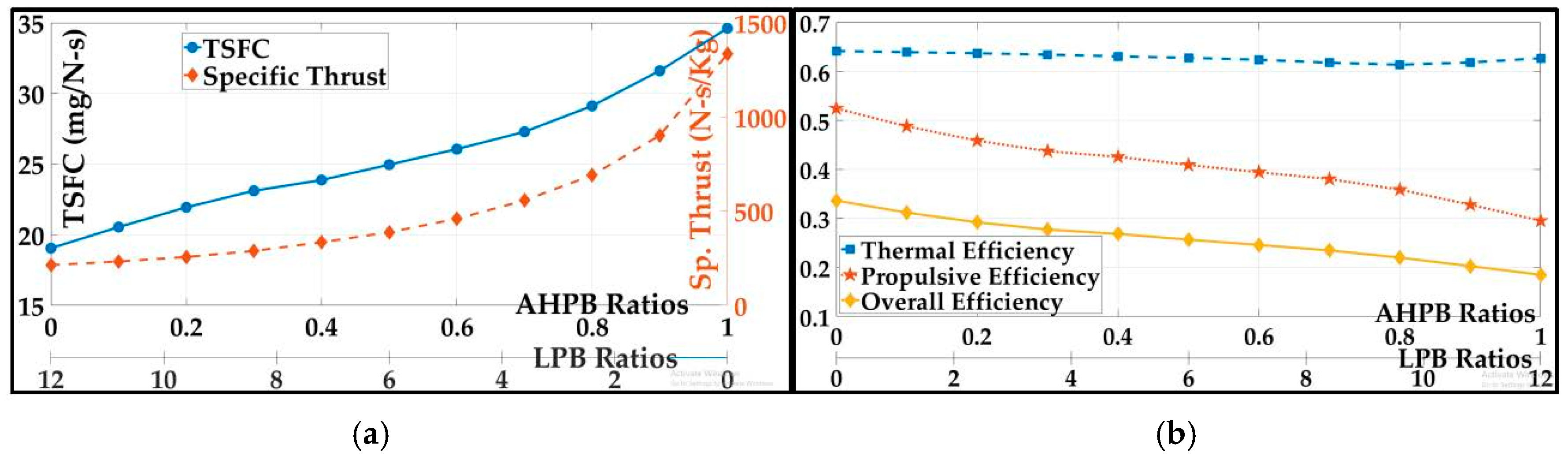
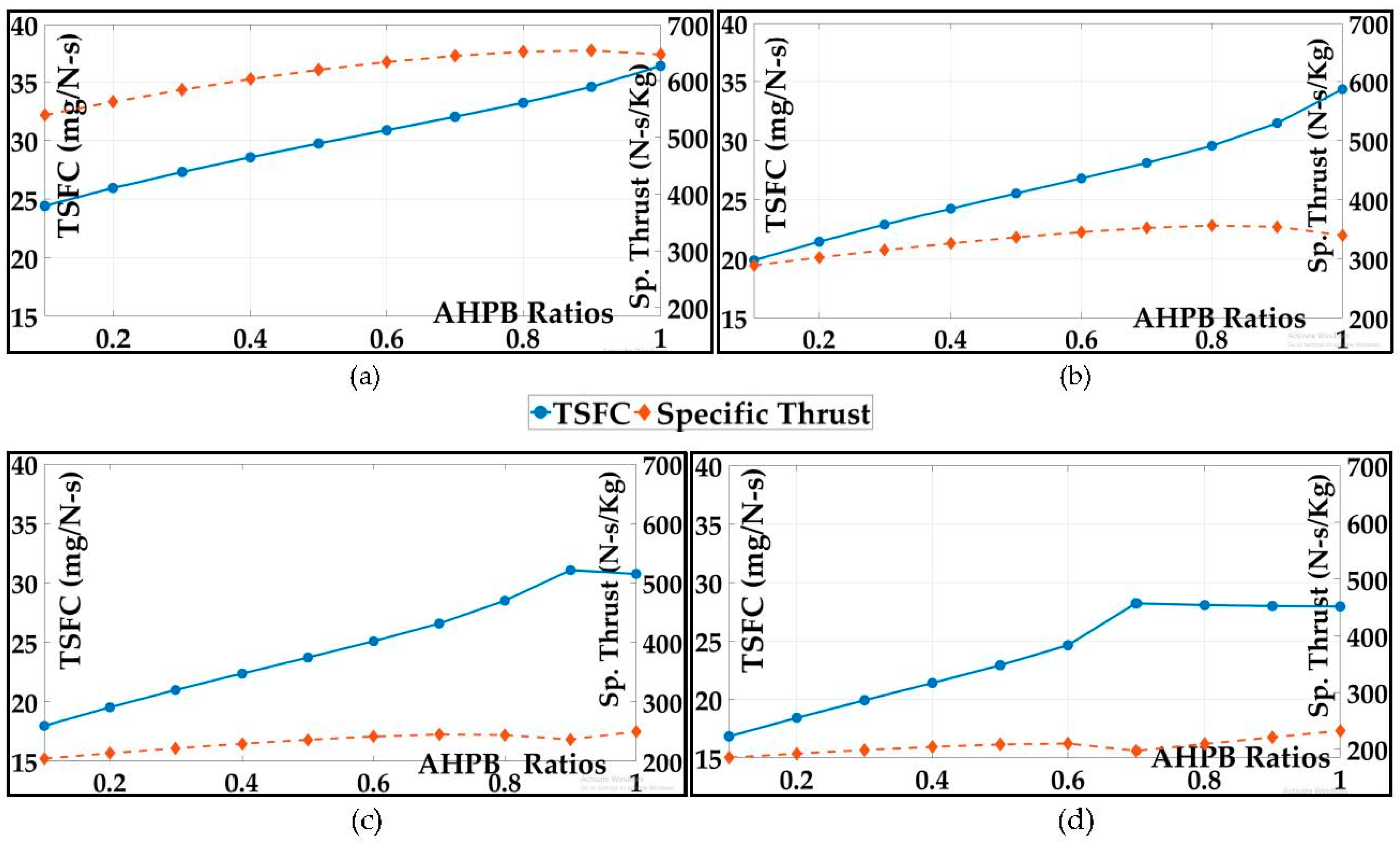
4.2.1. Thrust-Specific Fuel Consumption vs. Specific Thrust

To provide an insight into the utility of AHPB provision, the results of simulating these parameters as a function of varying AHPB ratios for various fixed LPB ratios are shown in Figure 4. The LPB ratios for the results shown in Figure 4 were chosen to be LPB = 2 (Figure 4a), LPB = 6 (Figure 4b), LPB = 10 (Figure 4c), and LPB = 12 (Figure 4d). As is evident from these results, the AHPB provision has a significant impact for aircrafts with relatively small LPB ratios. For an aircraft with an LPB ratio of 2, the specific thrust increases by ~20% for a ~40% increase in TSFC as the AHPB ratio goes from 0.1 to 1. Similarly, for an aircraft with an LPB ratio of 6, the specific thrust increases by ~20% for a ~70% increase in TSFC. Although the increase in specific thrust does not translate to a proportional increase in TSFC, it should be observed that a net increase in the specific thrust of an engine due to the introduction of an AHPB stream in a turbofan engine with a set LPB ratio is significant. The most critical inference of the simulation results presented in Figure 4 is that an AHPB provision may be more suited for turbofan engines with low LPB ratios.

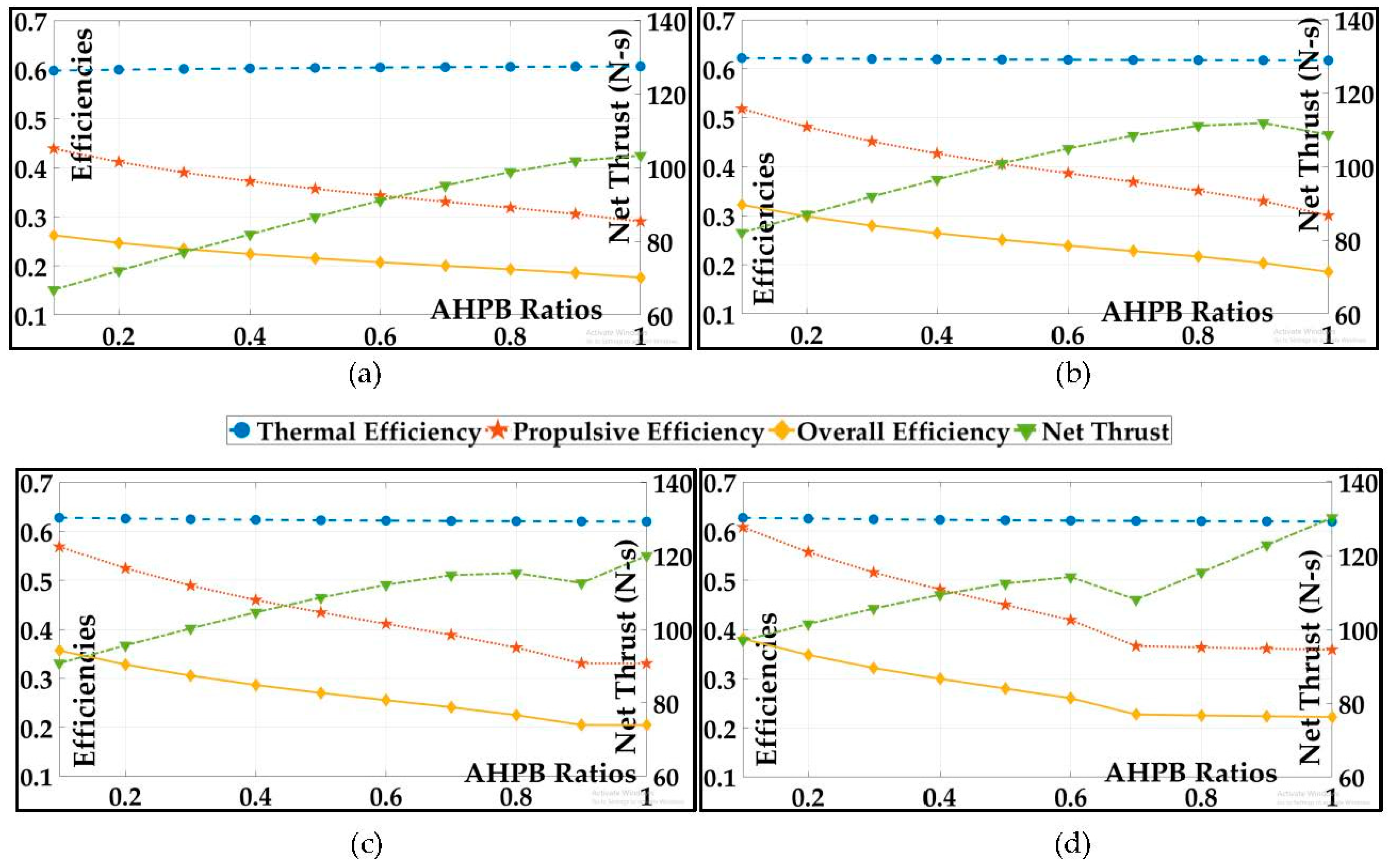
4.2.2. Efficiencies vs. Net Thrust

The plots of efficiencies vs. net trust as a function of varying AHPB ratios for various fixed LPB ratios is shown in Figure 5. For an aircraft with an LPB ratio of 2, the net thrust increases by ~60% as the AHPB ratio goes from 0.1 to 1. The propulsive efficiency of the aircraft with this configuration (LPB ratio = 2) decreases by ~30%, almost entirely contributing to the decrease in the overall efficiency by a similar amount. The impact on thermal efficiency is almost negligible. Similarly, for an aircraft with an LPB ratio of 6, the net thrust increases by ~35% as the AHPB ratio goes from 0.1 to 1. Here, the propulsive efficiency of the aircraft decreases by ~40%, contributing to the decrease in overall efficiency of 40%. It is easy to notice a trend in that the AHPB provision is more beneficial for aircrafts with lower LPB ratios.

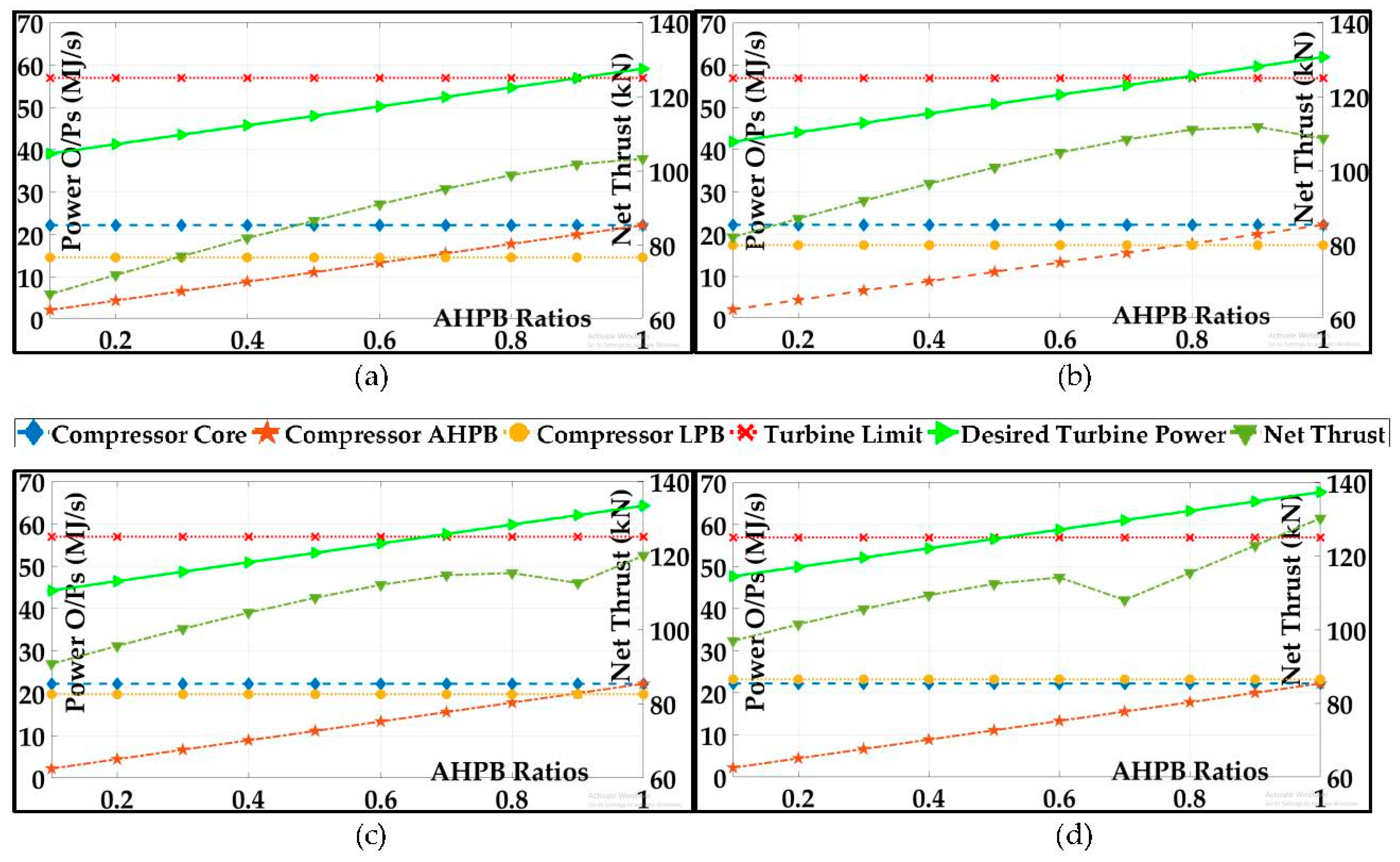
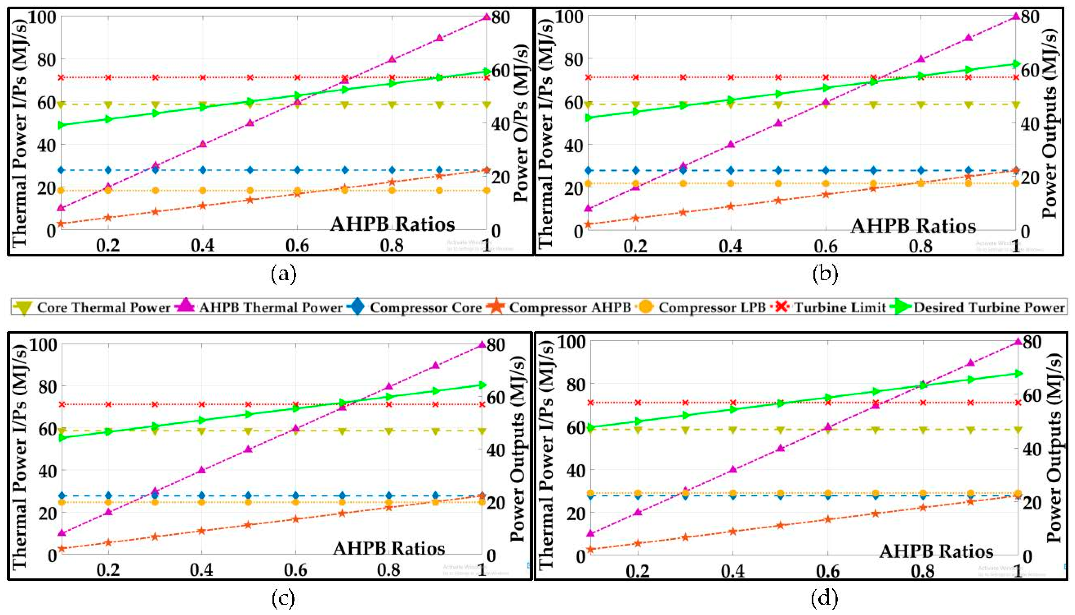
4.2.3. Power Input vs. Power Output

The plots of power input vs. power output as a function of varying AHPB ratios for various fixed LPB ratios are shown in Figure 6. In these plots, it is very critical to observe the turbine power limitation as a function of the varying AHPB ratios. It may be argued that in a 100% efficient system, all of the turbine power is used to drive the compressor and the fan. If the demanded power by the compressor and the fan exceeds the physical capacity of the turbine, there will be a drop in net thrust. In a conventional turbofan engine, accommodating a “variable-power” turbine has no utility. However, with the AHPB provision, an engine may benefit from a turbine of higher capacity for chosen power configurations of compressor and fan. This is evident from observing the various plots in Figure 6. For example, the capacity of the turbine may be >50% larger than that of a conventional turbofan engine with α L P B = 2 , when the AHPB ratio is varied from α A H P B = 0.1 to α A H P B = 1 . It is important to underscore that the AHPB thermal power input and the power output by the AHPB stream may be increased by an order of magnitude to accommodate the larger turbine. The larger-capacity turbine may be accommodated on any turbofan aircraft and, in times of urgencies, such provision may be exploited for increased performance.
The reader may observe that the slope of some of the parameters discussed in Figure 4 and Figure 5 (Figure 4c,d and Figure 5c,d) have a sudden drop for the turbofan engine with AHPH having fixed LPB ratios of 10 and 12. This drop can be attributed to the power limitation of the chosen turbine as can be seen in Figure 6c,d, where the desired turbine power exceeds the imposed turbine limit. The drops in the slope are seen at the AHPB ratio where the desired turbine power crosses the turbine limit. Overall, the plots shown in Figure 5 are a powerful representation of the utility of a turbofan engine with AHPB.

4.2.4. Power Output vs. Net Thrust

The plots of power output vs. net thrust as a function of varying AHPB ratios for various fixed LPB ratios are shown in Figure 7. It is clear from observing these plots that the major contributing factor to the net thrust, as the AHPB ratio varies from 0.1 to 1, is the power output of the AHPB. For the engine with a fixed LPB ratio of 2 ( α L P B = 2 ), when the AHPB ratio varies from 0.1 to 1, the net thrust increases by 60%. For this same variation, the demand on the turbine increases by 54%. If it can be argued that the form factor of an engine is determined by the size of the fan, then, for a pre-determined engine form factor, the net thrust of that engine may be increased by up to 60%. This is the case for an engine with α L P B = 2 . Such a feature would be highly desirable for an efficient military aircraft. As the LPB ratio increases, the potential overall increase in net thrust decreases. However, even for an engine with α L P B = 6 , the net thrust may increase by up to ~35%. For charter flights and private jets, which are conventionally designed around LPB ratios of 4 to 6, such a feature is highly desirable.

5. Conclusions and Future Work

An afterburner engine is commonly used to enhance the total temperature of the gas for obtaining an increase in thrust. In comparison, the turbofan engine with AHPB, which serves a similar purpose, receives air directly from the compressor with no prior depletion of oxygen. This feature facilitates efficient burning and reduces the specific fuel consumption of the engine. The AHPB provision in turbofan/turbojet engines also facilitates improved engine performance through the use of contemporary advancements in ceramic materials for high-temperature flows, among others. The turbojet/turbofan engines with AHPB, when compared with those without AHPB, may also be able to better facilitate the design and development of electric engines for hybrid aircraft. In ultra-efficient engine technology, high fan-bypass ratios require large engine diameters and airframes. An augmented low-ratio AHPB stream may be critical in facilitating an ultra-efficient engine with a more manageable airframe.
The article discusses the AHPB provision to be of a constant ratio for a turbofan engine. However, if the AHBP ratio can be dynamically varied through a valve set-up, a turbo-boost feature will be introduced into the engine. A turbofan engine with a variable AHPB ratio or turbo-boost engine can be intermittently used to increase the performance of the aircraft by expending more fuel. However, such a dynamic provision may present its own design challenges. A thorough analysis, which delves into a more practical design-point study and the utility of the turbofan engine with AHPB, is being undertaken. The AHPB jet velocity is anticipated to be a critical component for establishing an optimal split of power with the intent to maximize power and, consequently, the overall efficiency. The proposed engine may have significant utility for private charter aircrafts, and design-point analysis is being pursued with this foresight. It is interesting to note that adding a core afterburner in addition to an AHPB burner would result in an engine with a higher specific thrust. However, such a three-burner system would offer its own design challenges. Last but not least, the ability of the turbofan engine with AHPB to facilitate the design of a hybrid electric engine is also underway.

Author Contributions

The novel concept of Turbofan Engine with AHPB was conceived by S.F.A. The formulation for the novel engine was jointly developed by both authors. The simulations were carried out by S.A.A. and the results were analyzed and articulated by both authors. The manuscript was prepared and formatted according to the requirements of the journal by S.A.A.

Funding

This research received no external funding.

Acknowledgments

The authors would like to acknowledge the contribution of Vascar Godfrey Harris of Aerospace Science Engineering at Tuskegee University for providing invaluable insight into the study.

Conflicts of Interest

The authors declare no conflicts of interest.

Nomenclature

C p specific heat at constant pressure
C v specific heat at constant volume
γ = C p C v ratio of specific heat at constant pressure to specific heat at constant volume
R = C p C v perfect gas constant
M Mach number
p absolute pressure
p t total (stagnation) pressure
T absolute temperature
T t total (stagnation) temperature
m ˙ mass flow rate
h specific enthalpy
h t total (stagnation) specific enthalpy
α L P B low-pressure bypass ratio
α A H P B auxiliary high-pressure bypass ratio
a speed of sound
V flow velocity
F thrust
η efficiency
Q R calorific value
π c = p t 3 p t 2 compressor pressure ratio
π F = p t 13 p t 2 fan pressure ratio
TSFCthrust-specific fuel consumption
Subscripts
istation number
1i1 corresponds to low-pressure bypass stream or fan stream
2i2 corresponds to auxiliary high-pressure bypass stream
ffuel
corecore stream
AHPBauxiliary high-pressure stream
LPBLow-pressure stream or fan stream
effeffective

References

  1. Mattingly, J.D.; Boyer, K.M. Elements of Propulsion: Gas Turbines and Rockets, 2nd ed.; AIAA Education Series; American Institute of Aeronautics & Astronautics: Reston, VA, USA, 2016. [Google Scholar]
  2. Raymer, D.P. Aircraft Design: A Conceptual Approach, 5th ed.; AIAA Education Series; American Institute of Aeronautics & Astronautics: Reston, VA, USA, 2012. [Google Scholar]
  3. Rutledge, J.L.; Polanka, M.D. Efficiency of an Ideal Brayton Cycle with a Constant-Volume Interturbine Burner. J. Propuls. Power 2015, 31, 970–976. [Google Scholar] [CrossRef]
  4. Lee, A.S.; Singh, R.; Probert, S.D. Two-combustor Engines’ Performances under Design and Off-design Conditions. In Proceedings of the 45th AIAA/ASME/ISAE/IASEE Joint Propulsion Conference & Exhibit, Denver, CO, USA, 2–5 August 2009; pp. 2009–4838. [Google Scholar] [CrossRef]
  5. Sirignano, W.A.; Liu, W. Performance Increases for Gas-Turbine Engines through Combustion Inside the Turbine. J. Propuls. Power 1999, 15, 111–118. [Google Scholar] [CrossRef]
  6. MacIsaac, B.; Langston, R. Gas Turbine Propulsion Systems, 1st ed.; Wiley: Hoboken, NJ, USA, 2011. [Google Scholar]
  7. Hadhazy, A. Fly the Electric Skies. AIAA Bulletin, Aerospace America. July/August 2017. Available online: https://aerospaceamerica.aiaa.org/features/fly-the-electric-skies/ (accessed on 25 October 2017).
  8. Daggett, D.L.; Brown, S.T.; Kawai, R.T. Ultra-Efficient Engine Diameter Study; NASA/CR-2003-003; Boeing Commercial Airplane Group; National Aeronautics and Space Administration: Seattle, WA, USA, May 2003. Available online: https://ntrs.nasa.gov/archive/nasa/casi.ntrs.nasa.gov/20030061085.pdf (accessed on 13 January 2019).
  9. Farokhi, S. Aircraft Propulsion, 2nd ed.; Wiley: Hoboken, NJ, USA, 2014. [Google Scholar]
Figure 1. Schematic layout of the turbofan engine with an auxiliary high-pressure bypass (AHPB).
Ijtpp 04 00002 g001
Figure 2. Plots of (a) turbine power, and (b) thrust as a function of bypass ratios.
Ijtpp 04 00002 g002
Figure 3. Plots of (a) thrust-specific fuel consumption (TSFC) vs. specific thrust and (b) efficiencies as a function of bypass ratios.
Ijtpp 04 00002 g003
Figure 4. Plots of TSFC and specific thrust vs. AHPB ratios for (a) low-pressure bypass (LPB) = 2; (b) LPB = 6; (c) LPB = 10; (d) LPB = 12.
Ijtpp 04 00002 g004
Figure 5. Plots of efficiencies and net thrust vs. AHPB ratios for (a) LPB = 2; (b) LPB = 6; (c) LPB = 10; (d) LPB = 12.
Ijtpp 04 00002 g005
Figure 6. Plots of power input and output vs. AHPB ratios for (a) LPB = 2; (b) LPB = 6; (c) LPB = 10; (d) LPB = 12.
Ijtpp 04 00002 g006
Figure 7. Plots of power output and net thrust vs. AHPB ratios for (a) LPB = 2; (b) LPB = 6; (c) LPB = 10; (d) LPB = 12.
Ijtpp 04 00002 g007
Table 1. Simulation parameters and properties.
Input parameters M 0 = 0.88 p 0 = 15,000 Pa T 0 = 233 K
Air properties C p 0 = 1004 J k g γ 0 = 1.4 R 0 = 287 J k g
Gas properties C p 4 = 1152 J k g γ 4 = 1.33 R 4 = 286 J k g
C p 24 = 1241 J k g γ 24 = 1.30 R 24 = 286 J k g
Other parameters T t 24 = 2516 K T t 4 = 1922 K π c = 50 m ˙ 0 = 40 kg/s m ˙ f c o r e = 2.1199 kg/s
Table 2. Performance parameters for select turbofan engines with an auxiliary high-pressure bypass (AHPB). LPB—low-pressure bypass.; TSFC—thrust-specific fuel consumption; KE—kinetic energy.
UnitsTurbofan with LPB = 10 and AHPB = 0.2Turbofan with LPB = 6 and AHPB = 0.5Turbofan with LPB = 2 and AHPB = 0.8
Total air mass flow ratekg·s−1448300136
AHPB ratio 0.20.50.8
LPB ratio 1062
Total fuel mass flow ratekg·s−12.1199 + 0.3148 (core + AHPB)2.1199 + 0.7871 (core + AHPB)2.1199 + 1.2594 (core + AHPB)
Core jetm·s−1543.0468664.56781054.6523
AHPB jetm·s−11746.03441746.03441746.0344
LPB jetm·s−1538.1605589.4479654.4585
Net thrustkN132.0586124.9973113.9338
TSFCmg·s−1·N−118.437023.256829.6603
Specific thrustN·s·kg−1294.7736416.6578749.5648
Thermal power inputMega Watt (MW)102.2602122.0956141.9310
Propulsive power outputMW35.548733.647930.6698
KE rate differenceMW60.576771.818885.7482
Thermal efficiency59.24%58.82%60.42%
Propulsive efficiency58.68%46.86%35.77%
Overall efficiency34.76%27.56%21.61%

