1. Introduction
At a low Reynolds number, e.g., those that are common in unmanned aerial vehicles (UAVs) at high altitudes or small turbomachines, the losses due to increased friction resulting from thicker boundary layers play a significant role. The reduction in performance due to low Reynolds numbers can be estimated using correction equations [
1,
2,
3,
4], and can be as high as 10%. In
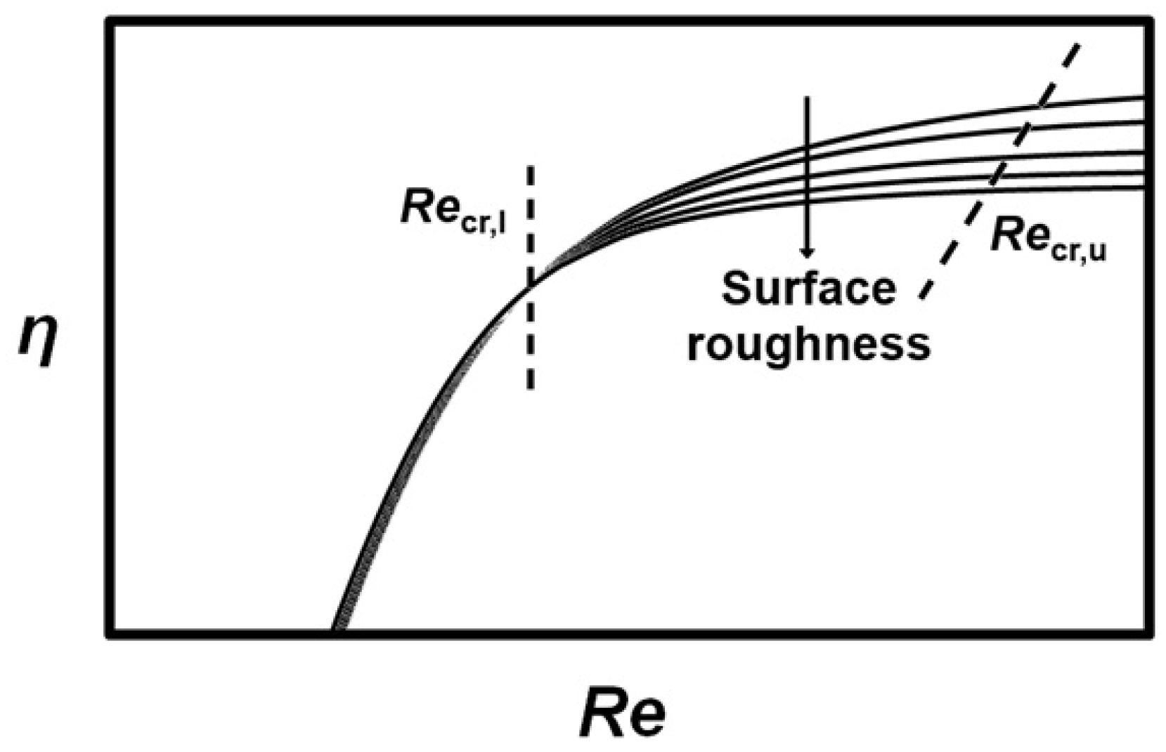
Figure 1, a schematic view of a change in compressor efficiency with a varying Reynolds number is presented. Below a lower critical chord Reynolds number (
= 200,000), efficiency decreases rapidly without an effect of roughness whereas above an upper critical chord Reynolds number
, the increase in Reynolds number no longer results in increased efficiency [
5].
In addition to increased friction, the performance of small turbomachines suffers from relatively larger surface roughness, blade thickness, and tip clearance. Because the surface roughness is limited by the machining process and the relative tip clearance is limited due to manufacturing tolerances and bearing technology, this review concentrates on decreasing friction losses using flow control. Researchers have tried to improve aerodynamic performance by applying various methods at different applications; for example, in axial and radial turbomachines, air vehicles and wind turbines. However, selecting an applicable method for reducing losses in low-Reynolds-number centrifugal compressors is not as straightforward since the flow field is complex and varies with different operating conditions.
The complexity of the flow field arises, e.g., from the flow separation near the centrifugal compressor leading edge. In centrifugal impellers, the secondary flow transfers low-energy fluid from boundary layer and feeds it into the wake. Centrifugal forces and the channel curvature strengthen the phenomenon by preventing the turbulent mixing of the wake and main flow regions. At the radial part of the impeller where the meridional curvature does not affect the flow anymore, the forces due to the impeller rotation still maintain the wake/jet structure, and the transport of low-energy fluid from the boundary layer keeping the boundary layers separated [
6].
The purposes of this review are to describe state-of-the-art flow control methods and discuss their benefits and drawbacks when applied in centrifugal compressors designed for low Reynolds numbers. Both high-altitude and small-scale machines, are accounted for in this review, as the loss generation mechanisms are similar in both and, therefore, the same methods are fundamentally applicable. The references cited in this review are mainly published from 2007 onwards. However, the investigation of a flow control method has been continuous for more than 10 years, thus earlier papers are included in this review to give a wider perspective of the research topic and to highlight its history.
Even though this review is focused on centrifugal compressors, the methods designed for both axial and radial turbomachines are examined as a means of establishing if radial machines could benefit from the knowledge gained in studies regarding axial machines, which mainly differ from the radial ones due to centrifugal effects. As a result of this review, the effects of different flow control methods are evaluated in terms of the compressor operating range and performance. In addition, conclusions are drawn about their applicability in low-Reynolds-number centrifugal compressors.
2. Classification of the Flow Control Devices
Flow control methods can be divided into active and passive methods depending on whether they require additional energy or not. To classify the methods presented in this review, the classification system used by Wood [
7] and Johnson et al. [
8] is utilised. Wood [
7] used the following five layer system of flow control methods to classify the actuators used in unmanned aerial vehicles:
Does the control require the addition of energy; i.e., is it active (A) or passive (P)?
Does the actuator move external geometry or add/subtract external fluid; i.e., is it geometric (G) or fluidic (F)?
Does the actuator operate unsteadily; i.e., is it steady (S) or unsteady (U)?
Is the goal of the actuator to attach (AT) or to separate (SE) the flow?
Does the actuator change lift (L), drag (D), or both lift and drag (LD)?
The categories are listed in
Table 1. Later, Johnson et al. [
8] modified the classification for categorising the actuators used in wind turbines (
Table 2) as follows:
Second layer: Geometric/Fluidic (GF) actuators use mechanical motion, which is not in contact with the external flow to generate motion of air into the external flow.
Second layer: Plasma (Pl) actuators generate a body force through the use of an electric field to modify external flow.
Third layer: Actuators that can operate both steadily and unsteadily are categorised as steady/unsteady (SU) actuators.
Fifth layer: Actuators, the goal of which is not to change lift and/or drag but to delay stall (DS).
Johnson et al. [
8] also used one layer to describe the location of the actuator according to whether it was near the leading edge (LE), at mid-chord (MC), or near the trailing edge (TE).
To categorise the flow control methods investigated in this review, only the first three layers of the classification system of Wood [
7] and Johnson et al. [
8] are used. First, they are divided into active (A) and passive (P) devices. The devices utilising active methods are discussed first and a discussion of the passive methods follows. They are further divided into geometric- (G), fluidic- (F), geometric/fluidic- (GF) and plasma- (Pl) based devices. The final classification is based on the operation in steady (S), unsteady (U) or in both steady and unsteady (SU) modes. These classes are presented in subsection titles describing the flow control methods. In addition to these three layers, the type of study is specified as experimental (E), numerical (N), or both experimental and numerical (EN) in the tables, in which most recent references are summarised. The methods are not classified based on the goal or use, because this review aims to introduce different goals and uses of the methods without generalisation, as one method can have several goals and/or uses.
3. Active Methods
Flow control methods based on active control require additional energy input and a control device, which enables the activation and deactivation of the flow control. Therefore, active methods can be used only when they are needed, and will not create additional losses when they are not needed, e.g., at high Reynolds numbers.
The purpose of the actuators is to reduce or eliminate flow separation [
9], reduce turbulent drag [
10] and/or reduce noise [
11]. Low-pressure turbines (LPTs) in particular are exposed to flow separation due to increased blade loading. The increased blade loading results from the current design trend, which aims to minimise the manufacturing and maintenance costs by decreasing the number of blades.
The operation of the actuators can be steady and/or unsteady. For actuators using periodic excitation (pulsed, unsteady operation), the excitation parameters, i.e., frequency, amplitude, and duty cycle, are important [
12]. The operation of the actuators is based on introducing additional momentum in the near-wall flow [
10,
13]. The momentum addition is evaluated using the momentum coefficient, which is the ratio of additional momentum to the main flow momentum. The actuators using the periodic excitation are effective in the momentum coefficient range of 0.01–3% [
13].
Table 3,
Table 4 and
Table 5 present the actuator investigations from 2004 to date. They show that drag and total pressure losses can effectively be reduced, but according to Quadrio and Ricco [
14], the maximum net energy saving is only 7.3% for the actuator which could reduce drag by 44.7% due to the energy used to control the actuator. In addition to the required energy input, actuators introduce additional weight and complexity into the controlled system [
10]. For example, the configuration of a pulsating jet [
12] is highly complicated, and therefore, it is used mainly in the wings of air vehicles that have a long chord length.
As
Table 3,
Table 4 and
Table 5 show, the most recently investigated active flow control devices are plasma actuators, synthetic jets, and vortex generator jets. Therefore, they are discussed in more detail below.
3.1. Plasma Actuator (Classification: Active, Plasma, Steady/Unsteady)
The purpose of a plasma actuator is to trigger transition and induce reattachment in separated flows by shifting high momentum fluid from the free-stream flow to the boundary layer. Plasma actuator research has been mainly concentrated on low-pressure turbine sections of gas turbines (
Table 3), in which laminar separation is likely to occur due to low Reynolds numbers. On an airfoil of an aircraft, the plasma actuators can control flow separation during take-off and landing, whereas during cruise conditions, they can reduce skin-friction, resulting in fuel cost savings [
15].
Moreau [
15] provided a thorough review of the use of plasma actuators for separation control in air vehicles. For the readers’ convenience, a summary of the review is given here. There are two main types of plasma actuators: The surface corona discharge (SCDA) and surface dielectric barrier discharge (SDBDA) actuators. Research on SCDAs started in the 1950s. In the SCDA, high-voltage direct current (DC) is applied to two flush-mounted wires. A corona is formed around the thinner wire creating an electric wind. This electric wind accelerates the airflow tangentially to the wall, resulting in a modified boundary layer [
15].
The advantage of SDBDA in reducing drag and boundary layer thickness was identified by Roth et al. [
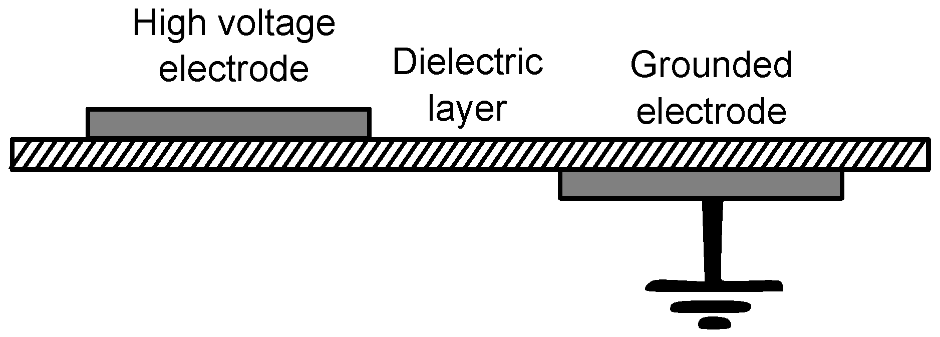
16] in 1998. In a SDBDA, two electrodes with a width of a few mm are asymmetrically separated by a dielectric layer (Teflon, Kapton, glass, ceramics, or Plexiglas) of a thickness ranging from 0.1 to a few mm, so that the upper electrode is located upstream and the lower electrode is located downstream [
15]. To the flow-exposed electrode, high-voltage alternating current (AC) (from several to tens of kV) with frequencies from one to tens of kHz is applied [
17,
18] and another electrode is grounded (
Figure 2). High voltage of a high frequency weakly ionises the surrounding fluid, producing plasma [
18,
19].
Nowadays, the SDBDAs are used more than the SCDAs since they provide more stable discharge [
15], and AC operation results in lower voltage requirement [
18] and low power consumption (order of watts) [
66]. On the other hand, the SDBDA may suffer from high peaks of electric input power under certain conditions; however, this may be reduced by using inductive filters between the power supply and the actuator [
15].
The progress in research has resulted in new actuator designs. In 2013, Wang et al. [
67] published a review of these latest designs. New designs include plasma synthetic jet actuators, plasma spark jet actuators, three-dimensional plasma actuators, and plasma vortex generators. Plasma synthetic jet actuators consist of an exposed electrode, embedded electrode and dielectric sheet. The fluid is ingested towards the actuator and ejected as a jet to the main flow. The advantage of the plasma synthetic jet actuators is acceptable power consumption (order of 100 W) [
66]. The experimental results of Neretti et al. [
68] indicated that the annular plasma synthetic jet actuator exhibits better performance than the linear version.
The plasma spark jet actuator consists of three electrodes. Plasma discharged into a small cavity due to an energy deposition increases the temperature and pressure of the fluid. The high-pressure fluid is ejected as a jet from the cavity to the main flow. The plasma spark jet actuator is based on arc discharges with high power consumption (order of kilowatts) [
66]. The plasma spark jet with a ram-air inlet was developed by Zhou et al. [
69] to overcome the limited working frequency due to the low refill rate of the cavity. The three-dimensional plasma actuator and plasma vortex generator causes vortices to re-energise the boundary layer. The three-dimensional plasma actuator consists of electrodes which have a gap between each other. Plasma vortex generators include either asymmetric (co-rotating vortices) or symmetric (counter-rotating vortices) rows of plasma actuators [
67].
A thorough review of the physics of single-dielectric barrier discharge (SDBD) plasma actuators was provided by Corke et al. [
18]. The benefits of plasma actuators are low power requirement, light and simple configuration (no moving parts, cavities or holes), no mechanical vibrations and fast dynamic response. At the same time, the plasma actuator requires power. The pulsed plasma actuator has proven to be more effective than the steady one [
36,
41,
44] and it uses less power than the continuous actuator. In a pulsed operating condition in which the voltage is cycled on and off, the duty cycle depends on the flow separation state [
33] varying between 5% [
33] and 60% [
36] in comparison to the steady actuator.
Recent research on plasma actuators has concentrated on the application of low-pressure turbines (LPTs) (
Table 3), in which the plasma actuators have proven their applicability in separation control, resulting in lift augmentation and loss reduction. Plasma actuators have also shown potential in jet mixing [
40], lift augmentation of air vehicle wings [
32,
34], suppressing vortex shedding over blunt bodies [
29,
37], suppressing endwall secondary flows in compressor cascades [
38], reducing noise [
11], and heat transfer augmentation [
70]. Benard et al. [
32] presented a parameterisation of the plasma actuator controller, but this discussion is beyond the topic of this review.
As the plasma actuators are used to trigger transition and induce reattachment, their applicability in centrifugal compressors is poor since the separation near the centrifugal compressor leading edge occurs due to centrifugal force and cannot be eliminated by energising the boundary layer.
3.2. Synthetic Jet (Classification: Active, Geometric/Fluidic, Unsteady)
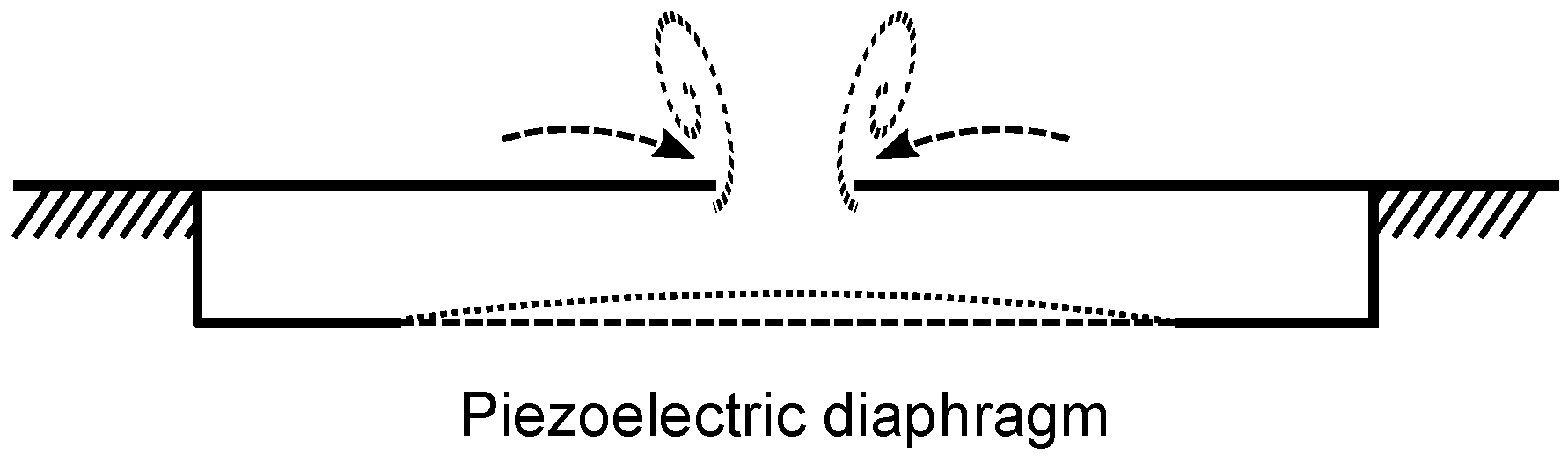
Synthetic jets use mechanical motion (e.g., oscillating diaphragm) to inject low-momentum fluid into a cavity and eject it as a high-momentum jet to the main flow (
Figure 3). Therefore, they are also referred to as Zero-Mass-Flux [
56] or Zero-Mass-Blowing [
13] jets. They are long and narrow spanwise slots that are located perpendicular to the airfoil surface [
52]. The experimental results of Stalnov et al. [
56] indicated that synthetic jets could replace passive vortex generators. The advantages of synthetic jets compared to passive vortex generators include lower drag and adjustability. In addition, their energy requirements, cost and weight are low [
56]. However, the actuator requires space inside an airfoil.
The most recent research to concentrate on synthetic jets is presented in
Table 4. As
Table 4 shows, synthetic jets have effectively been used at low-Reynolds-number applications (
) when laminar boundary layer separation occurs and when Mach number is less than 0.1. However, a recent numerical study conducted by Xu and Zhou [
50] indicated effective control of vortices when placed on the leading edge of UAV at high Reynolds and Mach numbers (2,128,000 and 0.6). To give another example of numerical studies regarding synthetic jets, Im et al. [
71] and Li et al. [
72] presented computational methods to reduce the computational cost of modelling synthetic jets, but these discussions are beyond the topic of this review.
Like plasma actuators, synthetic jets have poor applicability in both high-altitude and small-scale centrifugal compressors as they are based on boundary layer energising, which does not reattach the flow separated due to centrifugal force. In addition, they are effective to eliminate laminar boundary layer separation, which does not occur in centrifugal compressors. In addition, they require space for a cavity inside a blade, which practically limits their use to small turbomachinery due to material strength limitations.
3.3. Vortex Generator Jet (Classification: Active, Fluidic, Steady/Unsteady)
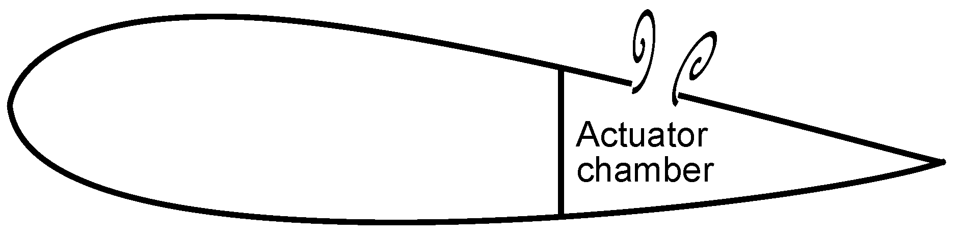
Vortex generator jets (
Figure 4) differ from synthetic jets in that they inject additional mass flow into the main flow from a compressed air supply [
12]. They are used, e.g., in combustors [
73]. The injected mass flow entrains high-momentum flow from the main flow into the boundary layer reducing boundary layer separation. The most important design parameters of vortex generator jets are injected mass flow rate, jet location and pulsating frequency [
74]. Vortex generator jets operating in unsteady (pulsed) operating conditions are more efficient than steady ones due to the reduced injected mass flow rate [
62,
65]. Kostas et al. [
64] found that a counter-rotating configuration for a vortex generator jet (which consists of two jets pointing to opposite directions and results in counter-rotating streamwise vortices into the boundary layer) is more effective than a co-rotating one (which consists of individual jets pointing to same direction and results in co-rotating streamwise vortices), since it requires less injected mass flow. The unsteady vortex generator jets increase skin friction making the boundary layer less prone to separation [
64].
The pulsating frequency yielding to a Strouhal number
of unity is recommended [
65,
75]. The recommendation of the Strouhal number of unity results from the flow instabilities which are of the same order of magnitude regardless of the airfoil span [
75]. As a thorough review of periodic excitation provided by Greenblatt and Wygnanski [
13] pays particular attention to optimum frequencies, they are not further discussed here. The effectiveness of the unsteady vortex generator jets has shown to be independent of the duty cycle down to 1% [
65]. However, the increase in wall shear stress is dependent on the injected flow rate [
64].
Like plasma actuators and synthetic jets, vortex generator jets are based on boundary layer energising, which does not reattach the separated flow due to centrifugal force. In addition, the requirement for compressed air makes the use of the vortex generator jet in a low-Reynolds-number centrifugal compressor challenging. On the one hand, hot air from the compressor outlet would lower the efficiency when recirculated to the impeller. On the other hand, the implementation of these methods would result in a complex system, which is not optimal in low-Reynolds-number applications in which size and weight are important. In addition, the holes for mass flow injection (hole diameter ranging from 0.5% [
61] to 2% [
9] of the chord length) are vulnerable to fouling [
8].
3.4. Geometric Actuators (Classification: Active/Passive, Geometric, Steady/Unsteady)
The above-mentioned active flow control methods including different actuator types are not valid in small-sized applications such as micro air vehicles or mini unmanned aerial vehicles because of the weight, volume and power consumption of the actuator [
75]. A review of Gursul et al. [
75] presented wing oscillation methods for increasing lift and delaying stall in low-Reynolds-number flows.
The presented flow control methods were as follows:
Rigid airfoils
- (a)
Deflected trailing edge vortices for pre-stall angles of attack (deflected jets)
- (b)
Convected leading edge vortices for post-stall angles of attack
Oscillating flexible airfoils induce reattachment by energising near-wall vortices and entraining momentum from the free-stream flow [
75]
Self-exited flexible airfoils: Membrane airfoils (light-weight, ability to change shape), shape memory alloys [
76]
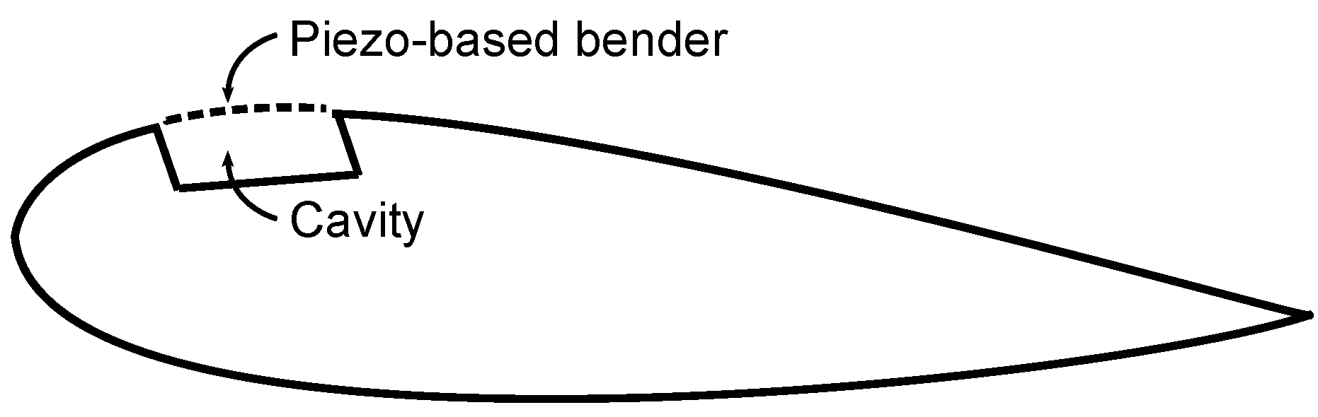
Macro-fiber composite actuators are used for active flow control in unmanned aerial vehicles [
77,
78]. Bilgen et al. investigated experimentally piezo-based benders (
Figure 5) on a NACA (National Advisory Committee for Aeronautics) 0010 airfoil profile with [
78] and without [
77] variable camber, camber variation being 0.25–4.35% in the trailing section. In the case of centrifugal compressor, the design parameter is blade angle distribution instead of camber and the blade angle at the blade leading edge being the most important parameter. Therefore, the camber variation in the trailing section of a NACA profile is not relevant when compared to the centrifugal compressor blade. The results indicated an increase in lift coefficient of 18.4% and 27.5% for an airfoil with and without variable camber, respectively, due to reduced separation. In addition, Phan et al. [
79] investigated numerically similarly deformable compressor stator blades. Their results indicated that laminar separation could be prevented by an adaptive blade.
The idea of using deformable blades to increase blade loading in a centrifugal compressor is interesting due to their lightweight and lack of power requirement. However, their applicability and advantage in centrifugal compressors should be investigated. The drawback of deformable blades in a centrifugal compressor might be the strength requirement, at least in small-scale machines operating at high rotational speeds.
4. Passive Methods
Passive flow control methods do not require additional energy. They are geometrical devices that cannot be switched on and off like the active control devices, and they affect the flow field whether they are required or not. Passive methods dominate flow control attempts due to the high cost-to-benefit ratio of active methods [
74]. The advantages of passive flow control methods include lift augmentation, drag reduction, reduced tip leakage flow and separation control. However, the drawback of passive methods is that they cause additional losses when they are not required. A number of methods have been investigated in the past, but the most recently investigated approaches were selected for this review and are discussed in detail in the following subsections.
4.1. Gurney Flaps (Classification: Passive, Geometric)
Gurney flaps were first used in race cars to increase down force. A Gurney flap is a short flat plate mounted at the trailing edge perpendicular to the chord line on the pressure side of the blade, as indicated in
Figure 6 [
80]. The recommended flap height is less than the local boundary layer thickness [
35,
80] and as shown in
Table 6, the studied flap sizes vary from 0.5% to 30% of the chord length. The flap increases lift by increasing pressure difference across the blade. The flap also produces a long wake, which can delay or eliminate the flow separation at the trailing edge of the suction surface. Gurney flaps have also been used for vibration control purposes. They can be implemented together with a plasma actuator at the airfoil leading edge [
35], or the plasma actuator can be implemented at the Gurney flap [
81]. In addition to these, Gurney flaps have been used together with dimples [
82], or with a trailing edge flap [
83]. The most recent review of the Gurney flap was published by Wang et al. [
80].
The Gurney flap has been found to increase both lift and drag [
84,
85] and tip leakage [
84]. With low Reynolds numbers when the separation occurs, the Gurney flaps decrease losses, but as the Reynolds number increases, the losses due to Gurney flap increase as well.
Measurements also show that the effect of a Gurney flap on lift coefficient is strongly dependent on an airfoil shape [
86]. According to Cole et al. [
86], the lift of aft-loaded airfoils or airfoils with a large separation region (20–30% of the suction surface) does not increase significantly or even decrease when a Gurney flap is added. The perforation of the Gurney flap has not been found to have any major impact on its efficiency either [
83].
Thamsen et al. [
84] experimentally investigated the effect of Gurney flaps on the performance of an axial pump. The sizes of the studied flaps were 0.7% and 1.4% of the chord length. The results indicated that the Gurney flaps increase the head of the pump (25% at the design point, 2870 rpm,
= 690,000) and widen the operational range. The head is increased due to the increased pressure difference between the pressure and suction sides of the blade. As a result of the increased pressure difference, the tip clearance flow also increases. In addition to lift, the Gurney flaps increase drag, resulting in slightly reduced efficiency.
Greenblatt [
90] studied the effect of Gurney flaps on the performance of the low-Reynolds-number (
) axial fan. The test facility consisted of two blades of the axial fan with Gurney flaps. The studied heights of the Gurney flaps were 10%, 20% and 30% of the blade chord length. Typically the height of the Gurney flap is from 1% to 5% of the chord. In addition, thin (
) and thick (
mm) Gurney flaps produced from plastic were compared. Compared to thin flaps, the thick flaps better maintained their shape but added more mass to the blades. All measured flaps produced higher pressures (the maximum pressure increase was 22% at the highest flow rate) than the blades without flaps. The isentropic efficiency was decreased due to Gurney flaps at lower flow rates whereas it was increased at higher flow rates in comparison to the blades without flaps. The 10% thin Gurney flap produced the greatest increase in efficiency (the maximum efficiency increase was 18% at the highest studied flow rate).
Byerley et al. [
96] used Gurney flaps on the pressure surface near the trailing edge of the turbine blade to prevent laminar separation. Laminar separation occurred on the suction surface of the turbine blade at low Reynolds numbers (based on inlet conditions and axial chord) of 28,000 and 65,000. The separation was prevented by the Gurney flaps, which turned and accelerated the flow toward the suction surface of the neighbouring blade. The size of the studied Gurney flap varied from 0.6% to 2.7% of the axial chord.
Bechert et al. [
85] investigated the differences between 2D Gurney flap, divergent trailing edge and Gurney flap, where the corner regime on the pressure side of the airfoil was filled so that a quarter of a circle was formed. The authors concluded that the improvement of the filled corner was only marginal and a smaller Gurney flap is better than a larger divergent trailing edge. As a conclusion, the modifications in Gurney flap geometry reduce the mechanical stiffness of the Gurney flap and make the geometry more complicated.
In addition, active Gurney flaps (deployable flaps or miniature trailing-edge effectors) have been under investigation [
88,
92]. Byerley et al. [
96] presented the need to retract the Gurney flap with high Reynolds numbers when separation does not occur, which would make the Gurney flap an active flow control method. Microtabs are small Gurney flaps that operate with an actuator. The advantages of microtabs include fast response, simple configuration, and low power requirements [
8]. Disadvantages include noise generation, air leakage, and installation challenges due to the limited space near the airfoil trailing edge [
8]. In 2010, Chen et al. [
93] investigated a jet-flap, which is an aerodynamic flap generated by a jet of air near the airfoil trailing edge. A jet-flap eliminates separation by increasing momentum on the airfoil suction surface, which results in higher loading.
To conclude, Gurney flaps are not structurally complex and they have low space requirement unlike the active flow control methods. Therefore, Gurney flaps could potentially be placed at the trailing edge of the blade in centrifugal compressors near stall conditions as they delay separation near the trailing edge and increase loading, resulting in increased efficiency and widened operating range. However, the applicability of Gurney flaps in other than stall conditions is poor since they increase drag and tip leakage. Therefore, they are not recommended in low-Reynolds-number centrifugal compressors.
4.2. Riblets (Classification: Passive, Geometric)
The drag reducing riblet structures found in nature (shark skin [
97] and bird beak [
98]) have inspired researchers to reduce drag in engineering applications. Riblets are small streamwise aligned grooves that shift turbulent vortices farther away from the surface resulting in decreased momentum transfer and wall shear stress [
99,
100]. The reduction of friction by means of riblets has been an active field of study at both the fundamental and application level, for example, Nieuwstadt et al. [
101], Bechert et al. [
102] and Lietmeyer et al. [
103].
The drag reductions that have been reported have typically been about 5% [
102,
104] but reductions as high as 13% have also been reported [
105].
Table 7 summarises the recent research on riblets. The strength of the pressure gradient can be determined using the Clauser parameter
. As shown in
Table 7, there seems to be a disagreement as to whether riblets are also beneficial with strong adverse pressure gradients. Nieuwstadt et al. [
101] drew attention to the difficulties associated with measuring the drag indirectly in the work by Truong and Pulvin [
106] and Squire and Savill [
107]. According to Nieuwstadt et al. [
101], the momentum balance cannot predict with confidence whether the drag is increased or decreased. Use of the drag balance measurement instead of the momentum balance measurement has led to results that indicate more effective drag reduction with increasing adverse pressure gradient [
101].
The drag reduction performance of riblets is higher at low Reynolds numbers than at high Reynolds numbers [
115,
116] and ice, fouling, and wearing weakens the drag reduction capability of riblets [
10].
The design of the riblets, that is, shape, spacing, positioning and angle, plays a major role in the achievable drag reduction. For example, Sareen et al. [
113] tested four different v-shaped (sawtooth) riblets on a wind turbine airfoil and found that the location of the riblet film, the Reynolds number, and the angle of attack influenced the performance of riblets. A drag reduction of 4–5% was found with optimal riblets placed in the turbulent region, whereas non-optimal riblets produced up to 10–12% drag increase.
Chamorro et al. [
111] found that v-type grooves produced the best performance on a wind turbine airfoil, roughly 6% maximum drag reduction in the expected operational range. According to Bechert et al. [
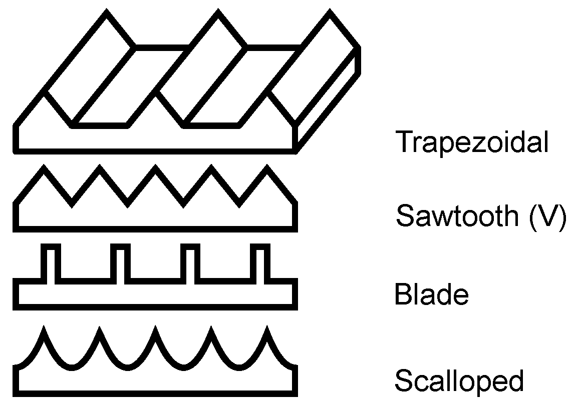
102], a trapezoidal riblet shape has a better drag reduction than a v-type riblet shape. Recently, trapezoidal riblets have been used on axial compressor blades because they represent the best compromise between drag reduction and structural strength [
117]. A recent review of the drag reduction performance of riblets, which was written by Dean and Bhushan [
118], concluded that the blade-shaped riblets provide the optimum drag reduction; however, due to their fragile nature, trapezoidal or scalloped riblets are recommended. In addition, the recent research shows that the blade-shaped riblets produce the best drag reduction [
97]. Examples of the riblet shapes are shown in
Figure 7.
The optimal size of the riblet can be evaluated in terms of the dimensionless riblet spacing:
where
s is the riblet spacing,
the friction velocity, and
the kinematic viscosity. Values of the dimensionless riblet spacing
in the range of 15–17 have been suggested [
99,
117]. The riblet spacing must be small enough (
), or otherwise one streamwise vortex would fit into one groove between the riblets resulting in increased drag [
102]. The optimal ratio between riblet height and spacing of
was suggested by Bechert et al. [
102].
In addition to the dimensionless riblet spacing
, the dimensionless wall distance
can be used as an optimisation parameter. García-Mayoral and Jiménez [
119] suggested that the breakdown of riblet performance is associated with spanwise quasi-two-dimensional vortices below
.
Positioning of the riblets also plays a major role in drag reduction. Lietmeyer et al. [
117] suggested that the riblet geometry should be adapted locally to the flow conditions because high riblets near the blade leading edge increase friction due to earlier transition resulting from a roughness effect. Drag reduction potential outside the separation region was pointed out by Lietmeyer et al. [
117], but was not investigated.
The fourth design parameter is the angle of the riblet. The experimental results of Lietmeyer et al. [
117] suggested the use of riblet tip that is as sharp as possible. A riblet angle of
or even
is technologically feasible according to Bechert et al. [
102]. The sharp riblet tip plays an important role in the effectiveness of the riblet; e.g., experimental and numerical studies of Miao et al. [
109] indicated that the aerodynamic performance advantage gained from the weakened passage vortex is cancelled out by the additional friction and mixing losses due to riblet surface quality at the turbine endwall.
For manufacturing riblets, grinding [
103], laser-structuring [
103], vinyl riblet films [
120], and nanoparticle-reinforced paints [
121] have been used.
The drag reduction potential of riblets could be utilised in centrifugal compressors if the riblets can be manufactured in the streamwise direction. The manufacturing of riblets could be feasible on shroud and/or hub surfaces of the impeller and diffuser but their drag reduction capability might be changed to drag increase at off-design conditions when the flow conditions vary from the design point.
As it was said in the beginning of
Section 4.2, the riblets are small streamwise aligned grooves. In
Section 5.2, grooves are discussed, but here the difference between the riblets and grooves is highlighted for the readers’ convenience. The grooves (
Section 5.2) at the shroud surface have shown potential in modifying tip leakage flow, resulting in more uniform flow field. However, these grooves are not aligned in streamwise direction like riblets and they are larger than riblets. Therefore, the increased wetted surface due to the grooves results in increased drag, whereas, in the case of riblets, the vortices do not fit in the small “grooves” between the riblet tips, but are shifted farther away from the surface, resulting in decreased drag.
The potential effect of riblets on centrifugal compressor efficiency can roughly be estimated based on their drag reduction potential. As the drag reduction is proportional to friction factor reduction, the increase in efficiency can be estimated based on the decrease in friction factor using the efficiency correction equation published by Dietmann and Casey [
4]. If the maximum drag reduction of 13% [
105] is assumed, the efficiency improvement varies in the range of 1–3% with a decreasing Reynolds number being greater below a lower critical chord Reynolds number of 200,000.
4.3. Squealers and Winglets (Classification: Passive, Geometric)
In addition to friction losses, tip leakage losses are higher in micro-scale low-Reynolds-number compressors than in larger compressors. Higher tip leakage losses result from relatively larger tip clearance in micro-scale compressors due to the manufacturing tolerances.
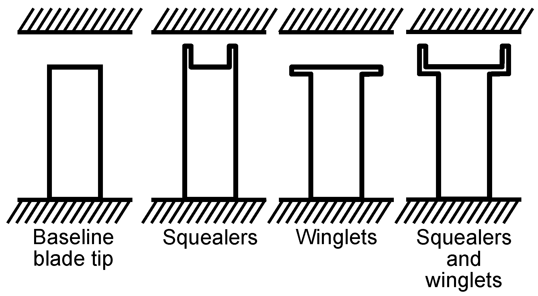
Squealers and winglets can be used to weaken tip leakage flow and they have been investigated separately and in conjunction in the literature (
Table 8). Squealers are vertical protrusions on a blade tip that point towards a casing. If squealers are applied on both the pressure and suction sides of the blade tip, a cavity is formed between them. Winglets are horizontal protrusions on a blade tip pointing towards adjacent blades. Schematics of squealer and winglet geometries are shown in
Figure 8. They can be applied on pressure, suction, or both sides of the blade, separately or together, and they do not have to cover the whole blade length.
The purpose of the squealers and winglets is to reduce the losses associated with tip leakage flow. The following principles for tip leakage flow control have been published:
Splitting the loading due to the tip leakage between the pressure and suction side squealers reduces losses [
122].
Thin squealers prevent the fluid from reattaching to their tip surface [
122].
Winglets weaken the passage vortex [
123].
Winglets decrease the pressure difference over the blade tip [
122].
Pressure side winglet weakens tip leakage [
124].
Pressure side squealer strengthens tip leakage [
125].
Different configurations of squealers have been under investigation since they can be applied on pressure, suction, or both pressure and suction sides separately or together with winglets. If the width of the winglets is so large that the winglets of adjacent blades touch each other, they form a partial shroud. Sometimes, ribs between the squealers are used. However, they have not shown any significant benefits in aerodynamic performance [
126]. Numerical studies have found that openings in squealers on the blade suction side at the leading and trailing edges can be beneficial [
127]. Due to the openings, the cavity vortex is strengthened and sealing effectiveness is improved [
127]. Among several squealer and winglet geometries, Schabowski and Hodson [
122] found the geometry with pressure and suction side squealers and winglets to provide the best total pressure loss reduction in a turbine cascade. Further optimisation of the geometry led to a geometry with squealers implemented on both pressure and suction sides, but the suction side squealer was on the top of the suction side winglet and the suction side leading edge was open [
128].
In a high-pressure turbine, the tip leakage flow is pushed farther away from the blade suction side by the winglet, resulting in reduced interaction between the passage and tip leakage vortices and losses [
127]. With increasing winglet width-to-pitch ratio (
), the tip leakage vortex stretches less towards the mid-span and the total pressure loss increases for
, decreases for
, and then becomes nearly constant [
123].
The effect of squealers on aerodynamic performance is connected to the operating conditions of a centrifugal compressor (improved performance at high flow rates, decreased performance at low flow rates) [
126]. Increase in squealer cavity depth reduces performance [
126], while the increase in squealer cavity width improves it [
126]. The study conducted by Da Soghe et al. [
126] indicated that the best efficiency gain was achieved with the squealer depth of 15% of the blade thickness and with the squealer width of 80% of the blade thickness. The study of Li et al. [
129] indicated that the best efficiency gain is achieved with the squealer depth of three times the tip clearance (1.38 mm) when the squealer is as wide as possible.
Ma et al. [
130] experimentally investigated the effect of suction-side squealer tip geometry on the performance of an axial compressor. They studied the tip leakage vortex behaviour using PIV and a statistical approach, and concluded that the squealer increased the static pressure rise but, at the same time, the tip leakage vortex was stronger and there was more reversed flow than in the baseline case. However, the leakage vortex dissipated faster behind the trailing edge with the squealer. The squealer geometry also caused a larger blockage in the blade passage. Thus, it could be assumed that the squealer geometry studied in the paper of Ma et al. would increase losses in micro-scale centrifugal compressor if it increased blockage and strengthened the tip leakage flow.
To conclude, the use of squealers and winglets with optimised geometry could be beneficial for small-scale compressor performance since they reduce tip leakage by decreasing pressure difference over the blade tip. In small-scale machines, the tip leakage losses increase due to relatively larger tip clearances. However, the effectiveness of the squealers depends on the compressor operating conditions; i.e., their performance is better at high flow rates than at low flow rates. In a small-scale centrifugal compressor, the squealer depth of 15% of the blade thickness would roughly mean approximately 0.05 mm and the width of 80% of the blade thickness would mean 0.28 mm (with a lower limit for blade thickness of 0.35 mm [
131]).
4.4. Turbulence and Vortex Generators (Classification: Passive, Geometric)
Passive vortex generators have been investigated recently in wind turbine applications [
143,
144,
145,
146,
147] where the flow separation reduces power at start-up and low wind speeds [
87]. In addition to the wind turbines, they have been investigated in centrifugal compressors [
148], tractor-trailers [
149] and aeroplanes [
150]. As the active vortex generator jets, passive vortex generators are used for separation control. In this review, dimples [
65] and tripping devices (tapes) [
148] are grouped into vortex generators.
Streamwise vortices generated by the vortex generators entrain high-momentum fluid into the boundary layer resulting in eliminated or delayed separation [
143] or induced reattachment [
151]. Similarly, the vortex generators affect the interaction between shock waves and boundary layers resulting in the reduction of shock-induced separation [
152]. The effects of vortex generators on shock waves have been thoroughly reviewed by Panaras and Lu [
152].
A number of different vortex generator configurations have been studied, and reported in the literature (
Table 9). At zero and adverse pressure gradient flows, joined and spaced vortex generator vanes, respectively, are effective [
74].
To delay the separation, the vortex generators should be placed close to the natural separation point [
146,
153,
154]. The vortex generators have been shown to delay the dynamic stall of wind turbines if placed at the leading edge [
145], to weaken the secondary flow in compressor cascade passage if placed at the endwall [
74], and to induce reattachment if placed on the suction side of the compressor blade [
74,
155].
In addition to vortex generator location, the device height and spacing are important design parameters [
87,
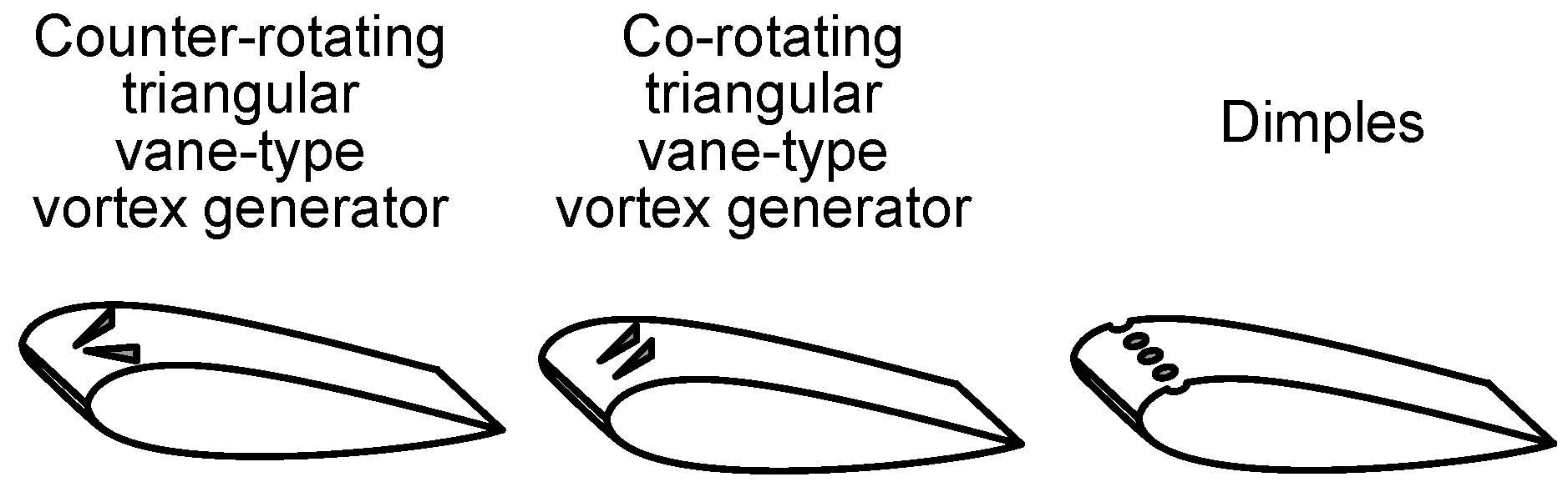
154]. A thorough review of low-profile vortex generators (with a device height from 10% to 50% of the boundary layer thickness) was provided by Lin [
154]. Lin investigated a wide range of low-profile vortex generators and concluded that the vane-type generators (
Figure 9) are the most effective at reducing the separation region. Tay et al. [
156] investigated dimples and concluded that drag reduction could be enhanced by increasing the dimple depth from 1.5% to 5% of its diameter, but increased dimple depth can result in increased flow separation causing additional drag. Therefore, deeper dimples are more suitable at higher Reynolds numbers.
Whereas the low-profile vortex generators should be located close to the separation point, Rivir et al. [
65] stated that dimples could effectively reduce separation and losses even when located after the separation point [
65]. However, the dimples are most effective when located upstream of the separation point [
65]. Dimples (
Figure 9) are affordable, robust, retrofittable, and manufacturable [
65]. Despite the advantages of dimples, with exception of the investigations of Zhao et al. [
155] and Ismail and Vijayaraghavan [
82], they have not recently been employed in turbomachinery applications. Zhao et al. [
155] found that dimples located at 30–60% of the chord length reduced the total pressure losses more than dimples located closer to the trailing edge. Their results indicated that the dimples either reduced the losses or had no significant impact; however, they did not increase the losses in the investigated incidence angle range of
. Heat transfer augmentation by the dimples [
157,
158,
159,
160] has been investigated more than their aerodynamic performance.
At low Reynolds numbers, wishbone type low-profile vortex generators are used on an airfoil [
154]. If vortex generators with the height,
h, between 10% and 50% of the boundary layer thickness are placed less than
upstream of the separation point, the size of the separation bubble is reduced resulting in a thinner turbulent boundary layer and reduced drag. On the other hand, at a small angle of attack (
), no significant lift augmentation or drag reduction on NACA 0012 airfoil has been found [
153].
Dimples are not as prone to fouling and wearing as riblets [
10]; however, they cause additional drag [
74]. The smaller the vortex generator, the lower the additional drag, but at low Reynolds numbers, a small vortex generator might not be sufficient to induce reattachment [
74].
To conclude, the use of vortex generators in a centrifugal compressor would require information about the separation point. As the ability of vortex generators to increase lift is based on induced reattachment, their applicability in an impeller of a centrifugal compressor is poor since the separation in a centrifugal compressor is caused by centrifugal force. The use of vortex generators in diffuser vanes might be an option, but the location of the separation point varies depending on the operating point.
4.5. Miscellaneous Passive Methods
Numerous additional flow control methods other than those already discussed have been investigated in the literature. This review is limited to those that have been investigated recently and are applicable in engineering applications.
By decreasing the incidence angle at the impeller blade leading edge, positive preswirl widens the compressor operating range [
161]. Whitfield and Abdullah [
161] used the variable inlet volute geometry with a rectangular cross-section to generate a positive preswirl. Because straight uncambered inlet guide vanes provide only zero incidence, aligned uncambered inlet guide vanes are inefficient due to large incidence angles and wakes, and cambered inlet guide vanes cannot be oriented to provide zero incidence.
Galindo et al. [
162] showed both experimentally and numerically that the negative preswirl generated by radial guide vanes can also decrease the incidence angle. Galindo et al. used the negative preswirl to overcome the non-uniformity of the flow field at the impeller inlet of the turbocharger. The non-uniform flow field was a consequence of the
bend near the impeller inlet. The incidence angle was reduced less with the negative preswirl than with the positive one, but in addition to a reduced incidence angle, the negative preswirl increased the pressure ratio, unlike the positive one. On the other hand, the efficiency was reduced due to negative preswirl.
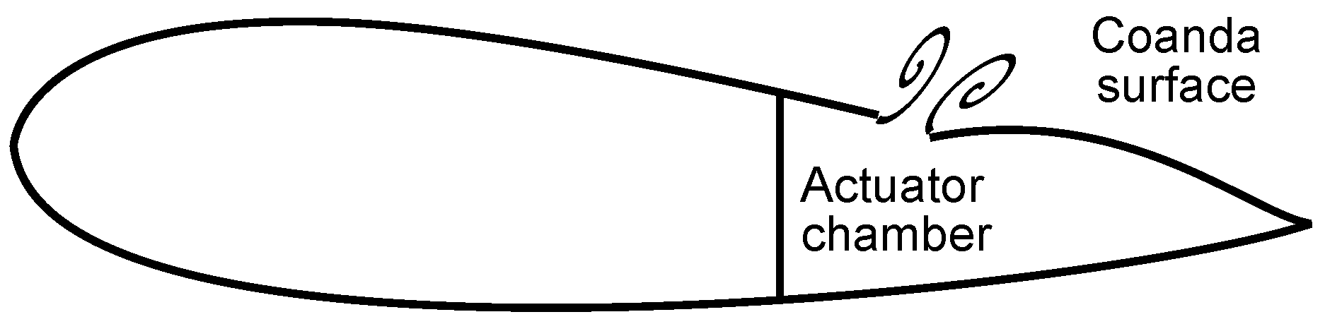
The numerical results of Guendogdu et al. [
163] showed that the number of compressor stator vanes can be reduced when jet flaps with Coanda surfaces (a curved surface near the trailing edge) are used, because the Coanda surface near the stator vane trailing edge increases the diffusion factor and maintains the exit flow angle of the reference case with more stator vanes and without Coanda surface. A passive Coanda surface has also been implemented together with an active jet flap stator, namely the vortex generator jet (
Figure 10), which shifts the separation point on the suction surface closer to the trailing edge and decreases the size of the trailing edge wake. Thus, the velocity gradient and total losses near the trailing edge are reduced.
Shahpar et al. [
167] numerically investigated the use of a profiled endwall to increase the performance of a turbine. They found that a profiled endwall affects more leakage flow in the hub side rim seal than secondary flows in the blade passage resulting in the maximum improvement in efficiency of 0.43%. Zaryankin et al. [
168] showed experimentally and numerically that streamwise fins on the stator vane passage endwall of a turbine reduce the total energy loss coefficient by around 12%.
In centrifugal compressors, the vortex generator jet with a Coanda surface could theoretically be beneficial in an impeller but the implementation of the vortex generator jet is not practically possible. However, the vortex generator jet might be replaced with a slot in the impeller blade, but as it should be located at the point of separation, it is beneficial only at one operating point.
5. Active and Passive Casing Treatments (Classification: Active, Fluidic, Steady/Unsteady and Passive, Geometric, Steady)
Active and passive casing treatments consist of flow control methods applied in turbomachinery casing, and have been developed to improve performance, increase stall margin, and enhance stability close to the stall [
169].
Table 10 presents an overview of the studies on active and passive casing treatments that were conducted from 2003 onwards. Applications vary from axial (AC) and centrifugal (CC) compressors to high pressure turbine (HPT) cascade and channel flows. The advantages of the investigations are presented as a maximum reported effect on machine efficiency, pressure ratio, operating range and/or surge margin.
Active casing treatments mean fluidic devices operating in steady or unsteady conditions. The high-momentum fluid is injected into the main flow to energise low-momentum fluid, and additional energy is used to inject the fluid. Passive casing treatments either recirculate fluid from higher pressure to lower pressure (e.g., from the compressor outlet to inlet) through recirculation slots or shift low-momentum fluid through grooves.
5.1. Injection, Suction, and Recirculation
A self-circulating casing treatment is a passive casing treatment in which the high-momentum fluid is recirculated from higher to lower pressure. In the past, the stall margin was improved by casing treatment; however, this reduced efficiency. Recently, the investigations have shown that, with the proper selection of casing treatment parameters, both the stall margin and the performance can be improved [
170]. The most important design parameters for a self-circulating casing treatment are the width and position of the bleed slot [
171,
172,
173], recirculation flow rate [
172] and casing porosity [
174].
Irsch et al. [
175] found that, in the case of a turbine blade, the optimum position for the injection tube is slightly on the blade pressure side at the trailing edge. The injection results in the reduced strength of the vortex oscillations, smaller vortices, and reduced total pressure loss. In an axial compressor, the optimum location for the injection is at the rotor blade leading edge, or upstream of it [
170,
176] and an injector throat height lower than four times the rotor tip clearance is recommended [
170]. In this optimum location, the injection acts on the tip leakage flow delaying the onset of stall.
In a centrifugal compressor, air is generally recirculated from the impeller or the volute to the inlet of the impeller. Wang et al. [
177] located the bleed holes near the separation point and the injection nozzle at the impeller inlet, whereas Skoch [
178] injected air into the vaneless space between the impeller and diffuser. The flow direction can also be radial in the bleed port, and air is injected far upstream of the impeller inlet. The numerical results of Tun and Sakaguchi [
172] indicated that the optimum location for the bleed hole is near the splitter blade leading edge.
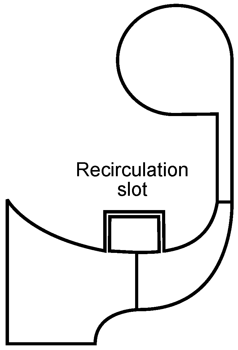
Figure 11 presents an example of a self-circulating casing treatment in a centrifugal compressor. High-momentum fluid is recirculated from the impeller to the impeller inlet through the recirculation slot.
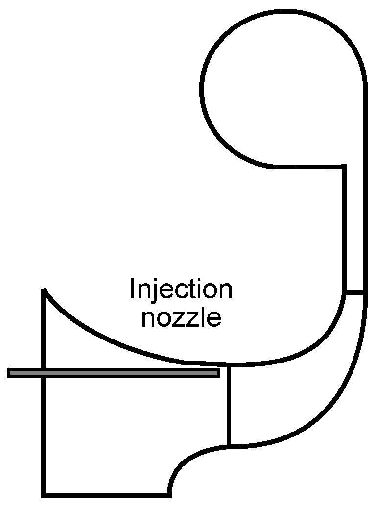
Nie et al. [
176] achieved a 10% increase in surge margin by implementing the injection in the impeller inducer.
Figure 12 shows a schematic view of the injection nozzle in the impeller inducer, where the high-momentum fluid is circulated from, e.g., the compressor outlet. Hirano et al. [
200] proposed that the optimum circumferential position for a single injector is on the opposite side of the volute tongue. For double injection, the optimum circumferential position for the first injection is between the volute tongue and the location at 30
to the rotational direction when the second injection is located at 135
from the tongue against the rotational direction, resulting in a 30% increase in surge margin [
193]. The increase in surge margin was related to reduced reversed flow in the diffuser close to surge [
193]. According to Zheng et al. [
173], the non-symmetric casing treatment around the shroud periphery improves the surge margin more than a symmetric casing treatment (surge flow rate being 10% lower with the non-symmetric casing treatment) due to the reduced circumferential flow distortion at the impeller inlet.
The injection of air from the compressor outlet to the hub in the vaneless space between the impeller and vaned diffuser has not provided any notable improvement in compressor performance [
201]. The best configuration (tubes of 10 mm in diameter and immersed from the shroud to a depth of 50% of the diffuser height) for the compressor stabilisation in the vaneless space between the impeller and the vaned diffuser improved the surge margin by 56%, but the pressure ratio was reduced by 5.5% [
178]. The lowest reduction in pressure ratio (−1%) was achieved by injecting air through nozzles in the streamwise direction, resulting in a 15% increase in surge margin.
In the vaneless space, the injection increases mass flow rate, resulting in increased radial velocity component and decreased absolute flow angle (
from the radial direction), which, in turn, prevents recirculation. Thus, the stable operating range is widened. The injection also increases blockage and decreases diffusion, in the vaneless space, resulting in a reduced pressure ratio [
178,
203]. Injection through the shroud surface recovers part of the operating range lost by the leakage flow through the labyrinth seal [
203].
Instead of injecting through the shroud surface, Skoch [
178] recommended stabilising the compressor with the tubes located on the shroud surface. The tubes bleed low-momentum flow from the vaneless space and decrease the flow area, resulting in an increased radial velocity component and a decreased absolute flow angle (
from the radial direction) at the diffuser vane leading edge, which prevents recirculation.
Jung and Pelton [
171] found that the greatest increase in the operating range and lowest reduction in efficiency is achieved with a slot area of 23% of the centrifugal compressor inlet area. If the bleed slot is shifted downstream from the impeller inducer, the compressor operating range increases but efficiency decreases [
171]. For a casing porosity, Wang et al. [
170] found the optimum value of 25%.
Both injection and suction are commonly used control methods in diffusers [
204], but they do not significantly improve the performance of the unstalled diffuser.
In the literature, the reported recirculation flow rate through the recirculation slot of a self-circulating casing treatment varied from 0.15% [
176] to an extremely high 80% [
183] of the main mass flow rate in the literature. Zhu et al. [
174] distinguished a linear correlation between the injection mass flow rate and stall margin improvement from numerical results.
Injection configuration is complex and increases the weight of the system due to, e.g., high-speed valves for air injection. Kern et al. [
184] managed to increase the injection mass flow rate by decreasing the injected primary mass flow rate while also utilising the ejector effect. Primary mass flow was injected from the high-pressure compressor, and it entrained an ambient secondary mass flow rate.
To conclude, the bleed-recirculation casing treatment with different bleed port and injection nozzle locations shifts the surge line to lower flow rates but it has a complex structure. In addition, injection configuration is complex and increases the weight of the system due to, e.g., high-speed valves for air injection. Therefore, the injection, suction or recirculation casing treatments could be beneficial for separation/stall control and surge margin improvement in larger compressors, but their applicability in small-scale machines is poor due to the space requirements. Furthermore, they do not reduce friction losses in low-Reynolds-number compressors.
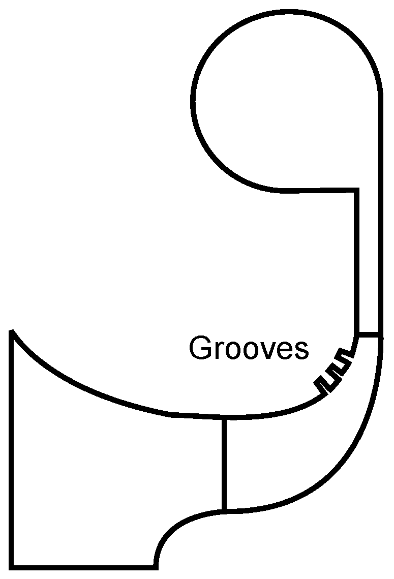
5.2. Grooves
Circumferential grooves at the shroud surface (
Figure 13) reduce the boundary layer thickness near the grooves. The grooves transfer low momentum fluid from the pressure to the suction side while energising it by decreasing the radial velocity and increasing the tangential velocity. From 4 to 8 grooves should be located near the separation point with a spacing of one-half groove width. It is recommended that the groove depth and width are approximately of the order of the boundary layer displacement thickness [
205].
Bareiß et al. [
169] experimentally and numerically studied the effect circumferential grooves at the shroud wall near the impeller trailing edge on the centrifugal compressor (
= 90 mm) had on performance. They studied the difference between the smooth casing and casing with 2, 3 or 4 grooves, respectively. The first three grooves from the trailing edge were close to each other, but the fourth was a bit more upstream. The results showed that the case with four grooves increased the pressure ratio but efficiency remained the same. The authors believed that the increased pressure ratio was caused by the grooves which increased the blade loading upstream of the groove. Because the first, second and third grooves were so close to each other, the loading could not be increased between them as much as upstream from the third and fourth grooves. Therefore, the authors speculated as to whether the first and second grooves near the impeller trailing edge were required at all. The efficiency was not improved due to additional friction losses because of the increased wall surface in the grooves.
In addition to increased blade loading, the grooves shifted the tip leakage flow further away from the blade suction side resulting in more uniform flow field at the impeller outlet. In addition, the wake was weakened and its size was reduced by the grooves. However, these mechanisms could not improve the efficiency, but balanced the additional friction losses.
Du [
181] compared circumferential grooves and axial slots in a mixed-flow compressor. Axial slots delay stall more effectively than circumferential grooves but at a higher efficiency loss. The optimum location of the circumferential grooves is in the middle of the tip chord. According to Du [
181], the axial slot can be optimised to produce a 26.4% improvement in surge margin with only 0.7% reduction in efficiency. However, the optimum parameters of a slot configuration depend on the compressor type.
Cevik et al. [
187] implemented grooves at the endwall of an axial compressor rotor to reduce the extent to which the compressor performance was sensitive to tip clearance size. Grooves did not enhance the performance but they decreased tip leakage over two adjacent blades and reduced performance and stall margin sensitivity to the changing tip clearance. The grooves investigated were sawtooth-shaped circumferential grooves with a depth of the tip clearance size.
Overall, grooves could be beneficial in low-Reynolds-number centrifugal compressors in which they increase the pressure-ratio and weaken the wake. Micro-scale compressors with relatively large tip clearances, in particular, could benefit from the modified tip leakage flow and more uniform flow field at the impeller outlet. However, the drawback of the grooves is that the increased wall surface results in additional friction losses so that the efficiency cannot be improved.
6. Theoretical Applicability in Low-Reynolds-Number Centrifugal Compressors
This paper presented a review of the active and passive flow control methods that have been used in numerous engineering applications.
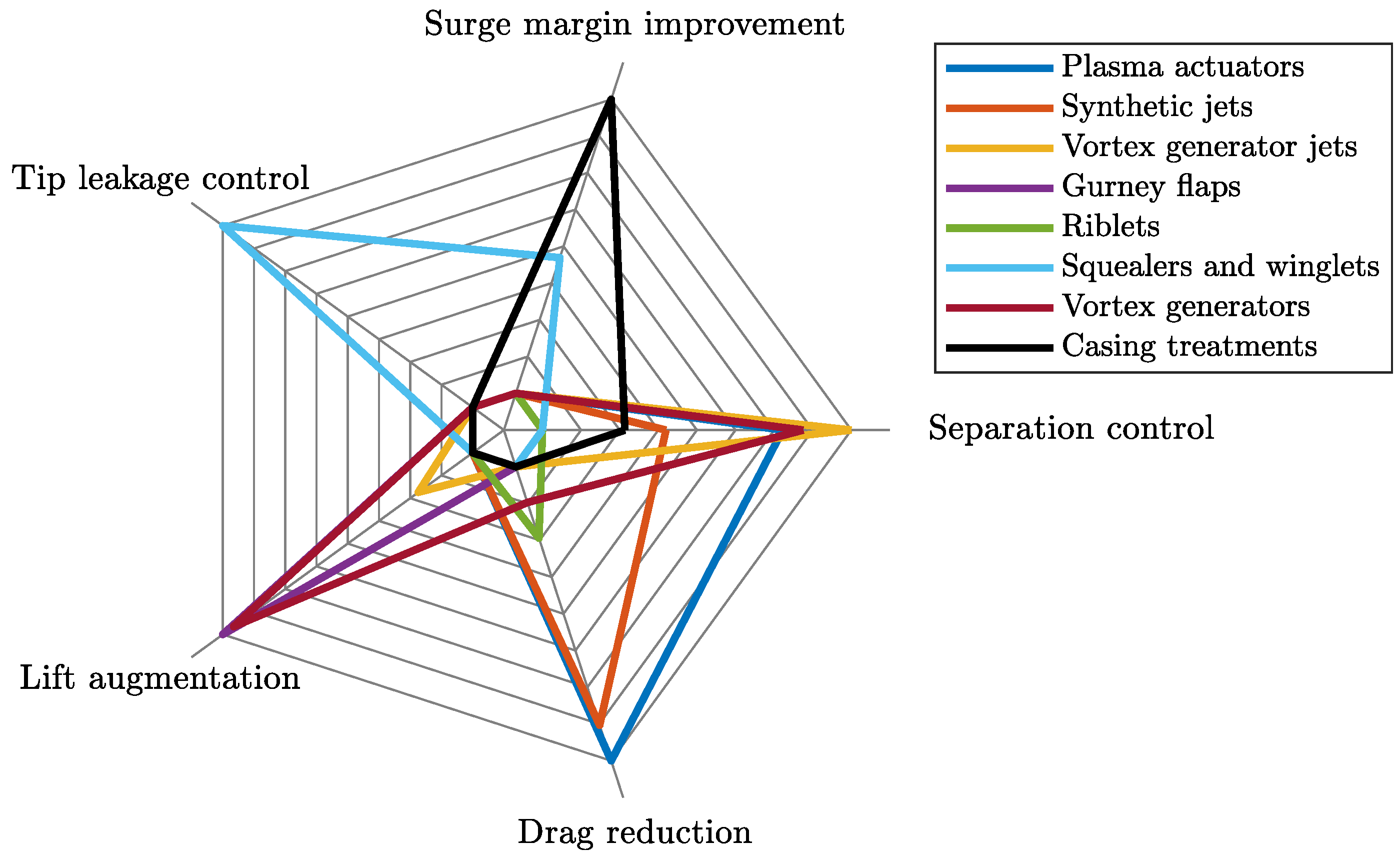
Table 11 presents a summary of the reviewed flow control methods, their purposes and working principles. The purposes are also illustrated in
Figure 14. Most of the methods described in this paper are applicable to drag reduction and separation control. The riblets reduce drag by decreasing wall shear stress, whereas the drag/total pressure loss reduction of plasma actuators and synthetic jets results from separation control.
The methods that are developed for separation control tend to trigger transition and induce reattachment of separated laminar flow. In centrifugal compressors, the separation in the impeller occurs due to centrifugal force. Therefore, the separation control methods that are based on boundary layer energising do not lead to reattachment in the impeller. In principle, the separation control could be beneficial, e.g., by passive turbulence and vortex generators in diffuser vanes, but the location of separation point varies depending on the operating point making the design difficult.
Boundary layer separation has also been prevented on low-Reynolds-number unmanned aerial vehicle airfoils through the use of geometric actuators such as piezo-based benders, which allow the airfoil to oscillate. Membrane airfoils, which allow the airfoil to change shape, could be an interesting research subject in centrifugal compressors, but in small-scale compressors that operate at high rotational speeds, their applicability would be limited due to structural demand.
Instead of separation control, the drag reduction and blade loading improvement would be more beneficial for improving the performance of low-Reynolds-number centrifugal compressors as the efficiency of low-Reynolds-number machines might be even 10% lower than that of high-Reynolds-number machines. Therefore, Gurney flaps could be potentially placed at the trailing edge of the blade in centrifugal compressors near stall conditions as they delay separation near the trailing edge and increase loading, resulting in increased efficiency and widened operating range. However, Gurney flaps are not recommended in low-Reynolds-number centrifugal compressors as they increase drag and tip leakage at other than stall conditions.
The drag reduction potential of riblets could be utilised in centrifugal compressors if the riblets can be manufactured in the streamwise direction. The manufacturing of riblets could be feasible on the shroud and/or hub surfaces of the impeller and diffuser but their drag reduction capability would be changed to drag increase at off-design conditions when the flow conditions vary from the design point.
In addition to increased friction losses in low-Reynolds-number compressors, relatively large tip clearances increase losses in small-scale machines. The losses associated with the tip clearance could be tackled with squealers and winglets. However, the effectiveness of the squealers depends on the compressor operating conditions; i.e., their performance is better at high flow rates than at low flow rates.
A restriction for using a complex flow control system in a small-scale machine is the additional weight of the control device. It is challenging to set a maximum weight allowable for the control device, as it depends on the application. A low-Reynolds-number centrifugal compressor can be a part of various applications, e.g., unmanned aerial vehicles, refrigeration systems, micro-scale gas turbines for distributed energy generation, etc. When the micro-scale applications are developed, the aim is to minimize the size and weight of the system. Therefore, in this manuscript it is assumed that any additional weight due to the flow control device should be avoided.
The bleed-recirculation casing treatment with different bleed port and injection nozzle locations shifts the surge line to lower flow rates but it has a complex structure. Injection configuration is complex and increases the weight of the system due to, e.g., high-speed valves for air injection. The grooves could be beneficial in low-Reynolds-number centrifugal compressors in which they increase the pressure-ratio and weaken the wake. In particular, micro-scale compressors with relatively large tip clearances could benefit from the modified tip leakage flow and more uniform flow field at the impeller outlet.
Overall, it is important that the flow control method does not deteriorate the efficiency of the centrifugal compressor although the operating range is widened. The flow control methods that require the actuator to be located at a fixed separation point are not applicable in centrifugal compressors, as the flow separates in the impeller due to centrifugal force and the separation point in the diffuser vanes varies depending on the operating point. The advantage of a widened operating range is low if the efficiency cannot be improved in the entire operating range of a low-Reynolds-number compressor as the passive flow control methods might deteriorate the efficiency in off-design conditions.
It would be beneficial for the low-Reynolds-number centrifugal compressor performance in the entire operating range if the size of the wake could be reduced, as the wake occurs in the blade passage at every operating condition. The wake is increased with the decreasing Reynolds number, as the secondary flows shift the low-momentum fluid from the relatively larger boundary layers to the wake. The boundary layer thickness of the baseline centrifugal compressor is approximately 1 mm, whereas in the micro-scale it is relatively 25–30% thicker but absolutely one tenth of the baseline boundary layer thickness being approximately 0.1 mm. The centrifugal compressors discussed in this review are assumed subsonic.
7. Conclusions
The aim of this review was to represent the state-of-the-art of the active and passive flow control methods used to improve performance and/or widen the operating range in numerous engineering applications. The applications include axial and radial turbomachines, air vehicles, and wind turbines. In addition, the purpose was to investigate the applicability of the flow control methods in centrifugal compressors in order to improve the compressor efficiency when operating at low Reynolds numbers.
To conclude, the selection of the flow control method depends on the application. The active methods, riblets, turbulence and vortex generators could be beneficial in a machine that mostly works close to its design point. The casing treatments and Gurney flaps would work in a machine in which the operating range needs to be widened without improving the efficiency near the design point. The use of a vortex generator jet or injection in a low-Reynolds-number centrifugal compressor is challenging as they require compressed air. On the one hand, hot air from the compressor outlet would lower the efficiency when recirculated to the impeller. On the other hand, the implementation of these methods would result in a complex system, which is not optimal in low-Reynolds-number applications in which size and weight are important.
In low-Reynolds-number centrifugal compressors, the method should increase performance by reducing drag, increasing blade loading, or reducing tip leakage whereas separation control is not a significant feature. In addition to aerodynamic demands, the flow control method cannot be structurally complex and it should meet structural demands. Based on these requirements, passive flow control methods, like riblets, squealers, winglets and grooves, could be beneficial in terms of the performance of low-Reynolds-number centrifugal compressors. The riblets with optimum geometry at the design operating point could potentially improve the compressor efficiency from 1% to 3% depending on the Reynolds number. Two studies on the squealers implemented in the centrifugal compressor indicate minor efficiency improvement (<+0.5%). One study on the grooves implemented in the centrifugal compressor do not indicate any improvement in the efficiency, but they have potential in modifying the tip leakage flow. However, the drawback of passive methods is that their performance depends on the operating conditions and might be negative at higher Reynolds numbers. The flow control method, which would reduce the boundary layer thickness and result in reduced wake, would be beneficial for low-Reynolds-number compressor performance in the entire operating range, but none of the methods represented in this review fully fulfils this objective.


