1. Introduction
The increasing interest in morphing structures has been fueled by research efforts and advances in innovative technologies, where the employment of smart materials, sensors, and actuators—as opposed to conventional solutions—has led to great improvements in system performance. Such technologies have proved to be effective both for the development of novel devices and for the upgrade of existing ones. This is particularly apparent in the aerospace domain where the ability to provide shape adaptation to optimally respond to hugely differing operation conditions, including those of the nominal design, is a key aspect [
1]. To overcome the issues related to conventional morphing architectures which are usually complex, bulky, and expensive, a challenging strategy is the use of smart materials. Among these, Shape Memory Alloys (SMAs) are a class of metallic materials with the ability to recover seemingly permanent strains, as a result of a temperature and/or stress induced solid phase transformation. By virtue of the so-called Shape Memory Effect (SME), SMAs are frequently combined within monolithic or composite host materials to produce morphing structures [
2]. Many studies have focused on active flow control by considering the employment of SMAs elements for actuation purposes. Examples of morphing applications regard the improvement of the global efficiency of aircraft wings [
3,
4,
5], noise reduction during aircraft take-off [
6], the development of a rotor blade control system [
7], the fabrication of actuators for tracking helicopter blades while in-flight [
8], and the application of aerodynamic control devices for wind turbine blades [
9,
10]. The notion of smart advanced blades, which can control themselves and reduce (or eliminate) the need for an active control system, is an appealing solution in blade technology to increase efficiency at several different flow regimes.
To analyze the performance of such morphing structures, experimental measurements coupled with a numerical approach should be considered. Focusing on the proposed morphing blade for an automotive cooling axial fan, the benefits of a blade with variable geometry are evident. In fact, fans of this sort usually involve a rotating hub bearing a ring of blades whose geometrical configuration has to be modified to optimize the airflow provided by the fan itself, in order to reach the optimal cooling conditions. The SMA-based morphing blade presented enables an optimal response to possible changes in turbomachinery operating conditions, avoiding any external actions on the shaft rotational velocity. Even though this solution has proved to be suitable in modifying the performance in agreement with the requests of the circuit [
11], the analysis of the displacement due to aerodynamic and centrifugal loads is essential for operation of the actual cooling fan. The deformation of the structure leads to changes in the fluid stresses which, in turn, affect the deformation of the structure itself. Given this background, it is evident that the complexity of the computational approach requires to consider both aerodynamic and structural physics, using the so-called Fluid Structure Interaction (FSI) simulations. In general, FSI modeling attempts to describe the interaction of a moveable and/or deformable structure that is immersed in a fluid and/or contains a fluid [
12]. FSI modeling has been a topic of great interest in recent years in the aeronautical field, mainly because advances in computer capacity together with the maturation of flow and structural modeling have made these coupled simulations feasible [
12]. In this respect, given that wind energy is one of the fastest growing forms of clean energy and this growth is set to continue, many recent efforts have been addressed, but are not limited, to investigate the effects of FSI on the power efficiency, stability, and life span of wind turbine blades [
13,
14,
15].
The present paper analyzes a novel concept of morphing blades for the performance optimization of an automotive cooling axial fan. Thanks to the thermally-activated phase transformation of the SMAs elements, the blades change their shape and the local flow field, thus adjusting the performance of the cooling fan according to the thermal requests of the engine. Based on previous thermomechanical characterization of the SMA elements and experimental data collected from wind tunnel tests performed on a single blade [
16], the present study is focused on the numerically-based analysis of the aerodynamic and structural behavior of morphing blades. The fan, composed of five morphing blades, was modeled by using the parametric solid modeler representation resulting from the three-dimensional blade surface captures obtained during the activation tests. The effects of the blade shape modification on the fan performance variation were studied by Computational Fluid Dynamics (CFD) numerical simulations of the scanned blades. Moreover, CFD analysis provided the aerodynamic load action on the actual blade shape resulting from the thermally activated phase transformation of the SMA strips. Aiming to simulate the actual blade shape under real operating conditions, the loads obtained by CFD numerical simulations were used for Finite Element Method (FEM) analysis to account for both the pressure and centrifugal loads during operation of the cooling fan. Structural analysis was performed to numerically evaluate the deformation of the blade by analyzing the effects of the aerodynamic load on (i) the designed blade shape (non-activated condition) and (ii) the deformed blade shape (activated condition).
CFD and FEM analyses are considered uncoupled and, therefore, the aerodynamic loads are only affected by the blade shape provided by the action of the SMA strips. This approach aims to provide information about the action of SMA strips and its relation with loads and blade shape in activated and non-activated blade configurations. Experimental results, related to fan performance and blade deflection, were compared with the numerical results of CFD and FEM calculations, showing good agreement and validating this type of approach.
2. Wind Tunnel Experimental Characterization
The morphing blade was intended to be a composite structure made up of a polymeric matrix, which ensured the structural integrity of the blade, and the embedded SMA strips, which were the actuator elements, thermally activated by a hot/cold airflow. The blade was designed in order to be compliant and flexible enough to support the large deflections induced by the strips and to allow shape recovery but, at the same time, stiff enough to withstand the aerodynamic loads. SMA strips were housed inside purpose-built slots in direct contact with the airflow and located in the range of about 50–85% of the blade span. A detailed description of the blade structure is reported in [
16].
With regard to the composition of the SMA strips composition, a commercially available NiTi shape memory alloy (Memry Metalle Company, Bethel, CT, USA), of nominal composition Ni
50.2Ti
49.8 was chosen. Starting from a 1.5 mm thick plane foil of material, the strips were cut to a dimension of 1.5 × 15 × 77 mm by means of electro-erosion machining. For the sake of brevity, the thermal characterization of the SMA strips which enables the evaluation of the transformation temperatures of the material and the thermomechanical treatment performed to memorize the shape, are not reported and more detail can be found in [
16].
The phase transformation of the SMA strips was achieved by an airflow obtained inside a purpose-built wind tunnel, which caused aerodynamic changes in the blade shape according to the airflow temperature. The experimental apparatus, named the Single Blade Test Facility (SBTF), was composed of (i) a convergent device, (ii) a polyvinyl chloride pipe, (iii) a flow straightener, (iv) a polymethyl methacrylate transparent measurement section, and (v) an exhaust pipe. The wind tunnel was driven by an axial fan with a nominal 1500 m
3/h flow rate that provided the airflow through a 22 kW electric heater. With the SBTF it was possible to create a highly-reproducible time-wise thermal gradient, capable of reaching values of up to about 12 °C/min in heating mode and up to about 6 °C/min in cooling mode. These temperature gradients are consistent with the operating conditions of fans when used normally. Several calibrated thermocouples were installed in the SBTF to control the airflow temperature. Type K welded tip thermocouples were also placed on the blade surface and on the SMA strips to acquire the temperature trends during the activation tests.
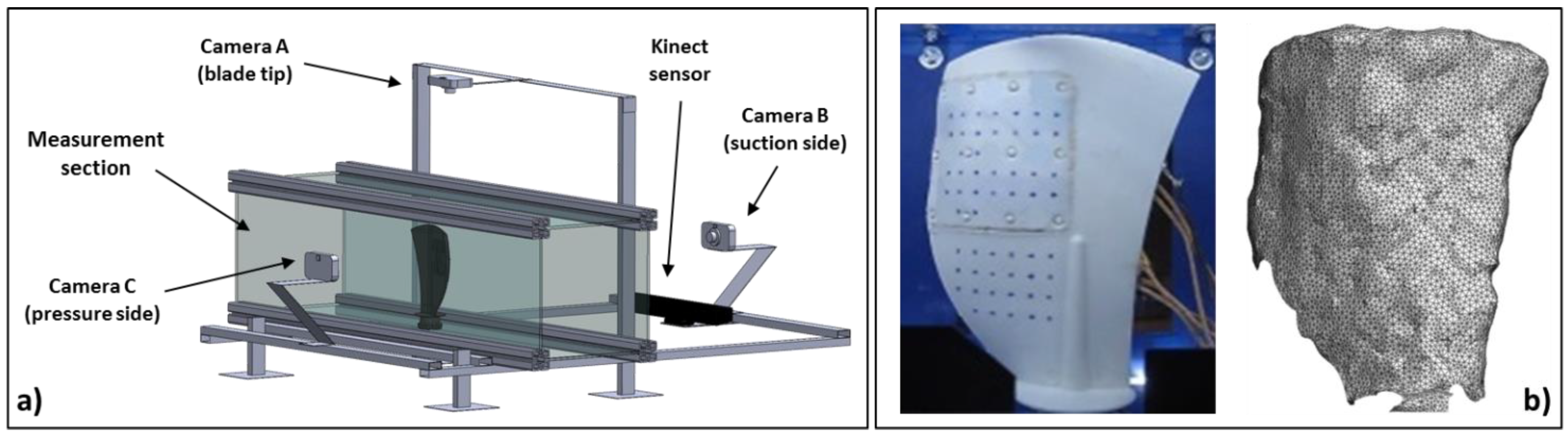
Figure 1a shows the SBTF measurement section in which the positions of the three cameras (blade tip, pressure side, and suction side views) are reported. The measurement section is also equipped with a Kinect sensor (Microsoft, Redmond, WA, USA) capable of providing streaming non-contact depth information and color information at a resolution of (640 × 480) pixels, with a rate of 30 frames per second. With this sensor, the shape changes upon activation of the blade were captured. An example of the ability of the Kinect sensor to detect the blade surface is reported in
Figure 1b. The suction side of the blade is reported first as the view of the camera and then as the point cloud (used for the subsequent solid modeler reconstruction) provided by the Kinect sensor. An evaluation of the accuracy of the Kinect sensor to detect the blade surface is reported in [
17] and a full description of the experimental apparatus and its thermal performance behavior can be found in [
18].
The SMA thermal activation and the resulting blade deflection were achieved by (i) a heating ramp and (ii) a cooling ramp, described as follows. Starting at room temperature, the blade was first heated by hot airflow from the fan and electric heater, and was subsequently cooled down to room temperature when the heating system was switched off. During the heating ramp, the SMA strips tended to recover the memorized bent shape and the blade structure was forced to bend. The modification of the blade shape was continuously evaluated by means of digital image analysis techniques [
16].
Figure 2 shows the comparison of the digital captures from the recorded video at the blade tip view for the blade shape at the initial condition (non-activated) and at the maximum deflection (activated). The final deformed shape of the blade is the result of the combination of the load provided by the SMA strips and the stiffness provided by the polymeric matrix. The blade shape change in terms of mean line deflection develops on each blade-to-blade plane as a function of the blade span location. As a result, the centrifugal force that works during operation of the actual blade does not influence the blade shape modification. SMA strips determine the airfoil deflection along the chordwise direction without being affected by the centrifugal force that works along the blade height.
Through the Kinect sensor, the non-contact 3D surface detection of the blade shape was also evaluated. In particular, the instant detection of the three-dimensional blade shape during the activation test allowed detection at (i) the start of the thermal cycle and (ii) the end of the heating ramp at the peak temperature.
3. CFD Analysis
Starting from the scanned blades and the solid modeler reconstruction extensively reported in [
17], two numerical domains were generated in order to analyze the performance of the fan by means of CFD numerical simulations in non-activated and activated conditions. The CFD analyses reported in this paper are taken from previous works [
11] and, for the sake of completeness, this paper reports the numerical model setup and the cooling fan performance, though additional information can be found in [
11].
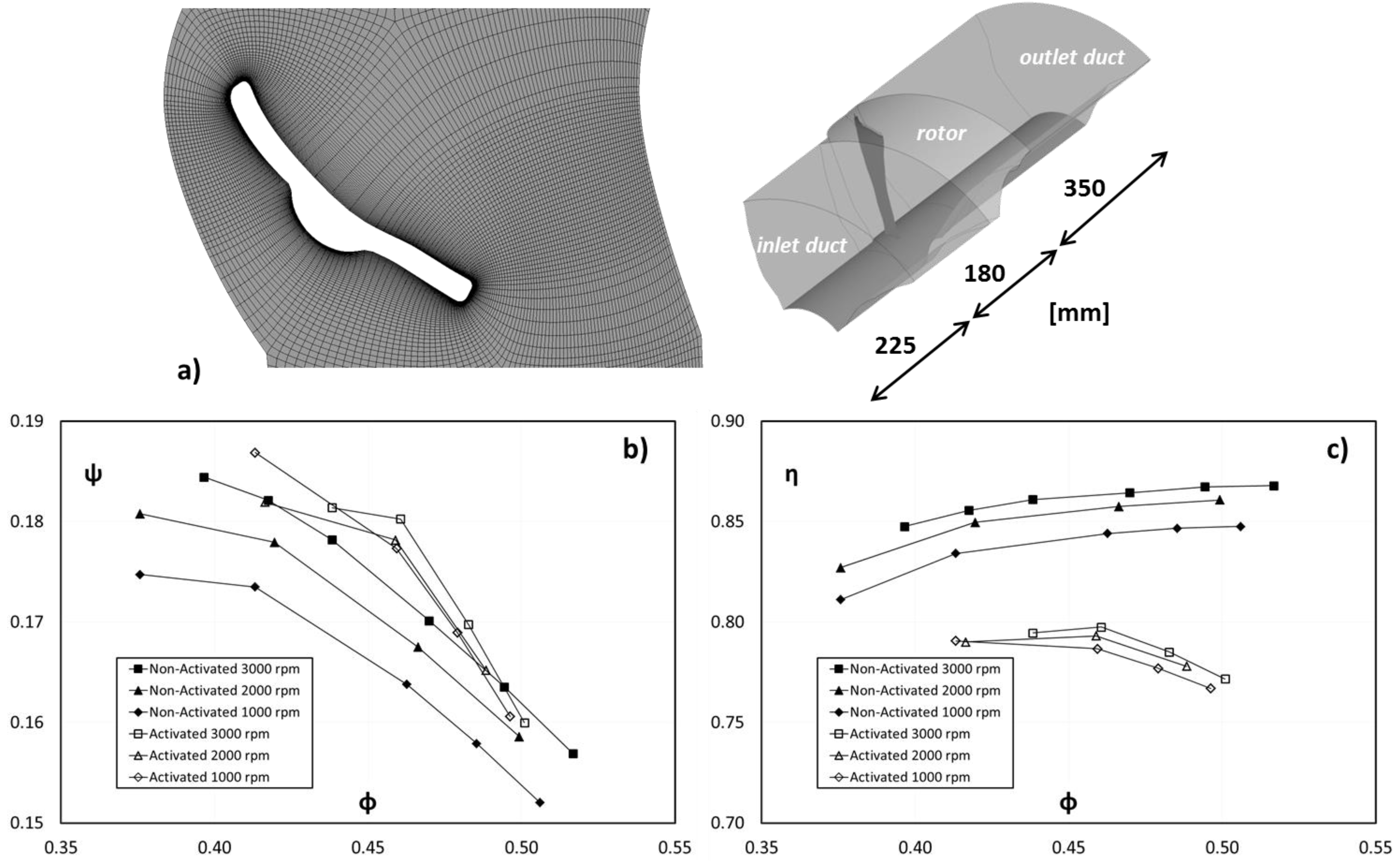
The numerical simulations were carried out by means of the commercial CFD code ANSYS CFX 15.0 (Canonsburg, PA, USA). All the simulations were performed in steady multiple frames of reference by using a frozen rotor interface. The fan was composed of five blades but only a single passage vane was modeled. The hub to tip ratio was 0.319, while the tip clearance was 5 mm (3.02% of the blade span). A multiblock hexahedral grid was generated for the numerical domains and each mesh was composed of about six million elements. In the three numerical domains the element size and the mesh refinement close to the wall were comparable. The
y+ value on the blade surface varied in the range of 4–90 for both of the numerical domains at the best efficiency point. A simplified sketch of the numerical domain with its dimensions, and the computational mesh closed to the blade, are reported in
Figure 3a. The numerical simulation was carried out for three different rotational velocities 1000, 2000, and 3000 rpm. Since only a section of the full geometry was modeled, rotational periodic boundary conditions were applied to the lateral surfaces of the flow domain. The standard k-ε turbulence model with a scalable wall function was used.
The performance trends in terms of flow coefficient ϕ and pressure coefficient Ψ are reported in
Figure 3b. The performance of the non-activated blade refers to the filled dots, while the activated blade is marked with empty dots. Differences in terms of the pressure and flow coefficient between the maximum and minimum rotational velocity are due to the different fluid dynamic phenomena characterizing the operating conditions of the fan in this rotational velocity range.
As shown in the extensive fluid dynamic and performance analysis reported in [
11,
17], the fan with the activated blades shows a higher pressure coefficient at the same flow coefficient. In particular, this performance gain is equal to 3% at the best efficiency point of the fan with the activated blades. The increase of the pressure coefficient is directly related to the increase of the airfoil camber (see
Figure 2) and permits a higher flow rate during the fan operation. In particular, when the fluid temperature rises, the blade shape modification generates an increase of the pressure coefficient and, in turn, a higher flow rate through the heat exchanger. Due to the meanline modification, the fan efficiency η decreases according to the blade activation. Fan efficiency refers to the ratio between fluid power (
Q Δ
p0) and shaft power (C ω). As depicted in
Figure 3c, the efficiency of the activated blade is lower than the values obtained for the non-activated blade. Due to the camber modification, the fan efficiency reduces as well as the stall margin and thus the activated blade experiences flow separation at the suction side. For this reason, the operating range of the activated blade is limited to a flow coefficient higher than 0.42.
4. FEM Analysis
As reported in the previous paragraphs, the SMA strips recover the memorized bent shape during thermal activation thanks to the thermal input provided by the airflow stream. For the intended application, the strips work against (i) polymeric matrix stiffness [
16] and (ii) aerodynamic and centrifugal loads provided by operation of the cooling fan.
Therefore, in order to establish the actual blade shape during operation, it is necessary to couple the CFD analysis, which provides the aerodynamic loads related to the blade shape, with FEM analysis based on pressure and centrifugal loads. Since the operation of SMA strips is based on the relationship between the memorized bent shape and the blade shape in activated condition, knowledge of the displacement due to the aerodynamic/centrifugal load is fundamental for operation of the actual cooling fan operation and could be suitable for tuning the thermomechanical treatment of the SMA. In literature, several applications can be found regarding the analysis of the aerodynamic/centrifugal load applied to composite structures and for a wide range of material stiffness [
19,
20].
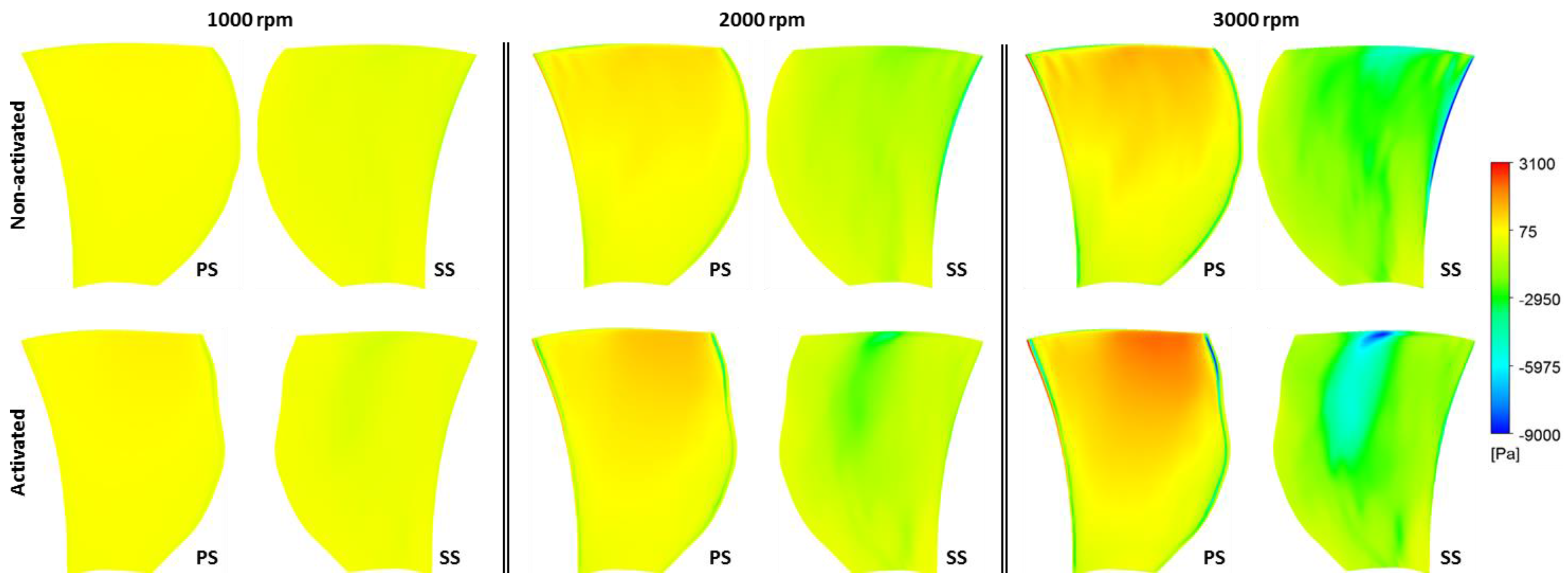
In this paragraph, the FEM analysis of the blade is proposed. FEM analysis refers to the blade configuration reported in the paragraph regarding CFD analysis: (i) non-activated and (ii) activated conditions for different rotational velocities of 1000, 2000, and 3000 rpm. The solid models of the blade are the same as those used for the CFD analysis, reconstructed from the three-dimensional blade shape acquisition provided during the wind tunnel activation tests. Pressure fields were obtained from the CFD numerical results and then exported to the FEM setup stage as pressure loads, matching the structural computational mesh. The mapping criterion used for the pressure load transfer conserves the pressure profile matching the structural mesh node using a triangulation strategy (distance weighted algorithm).
Figure 4 reports all pressure fields for the Pressure Side (PS) and Suction Side (SS) of the non-activated blade and activated blade.
The FEM analysis was realized using unstructured tetrahedral elements. The SOLID92 type elements were used as they have quadratic displacement behavior and are well suited to modeling irregular meshes. The element was defined by 10 nodes with three degrees of freedom (translational according to the coordinate axis) at each node. The element also has plasticity, creep, swelling, stress stiffening, large deflection, and large strain capabilities. The meshes were built of about 240,000 elements, allowing a thickness resolution with four elements. As mentioned above, FEM analysis considered the load provided by the pressure field and the centrifugal force due to the rotation of the cooling fan. Finally, the FEM setup closure was realized by imposing a fixed support at the blade root. Therefore, the blade root and its connection with the fan hub were considered infinitely stiff. The polymeric matrix structural characteristics were also specified. In particular, the polymeric matrix had a density value of 1230 kg/m3, a tensile yield strength value of 85 MPa, and a tensile ultimate strength value of 81 MPa.
Since the present paper begins with the morphing blade shape, FEM results were related to the blade deformation due to loads and no results are reported regarding strain. The blade structural integrity is guaranteed by material selection and characterization, as reported extensively in previous analysis [
16].
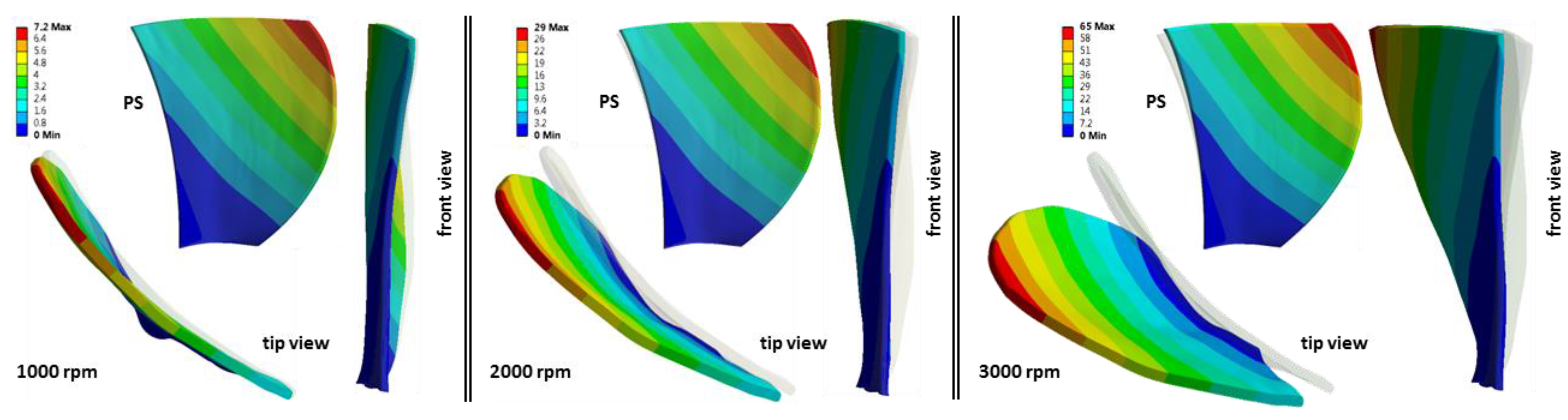
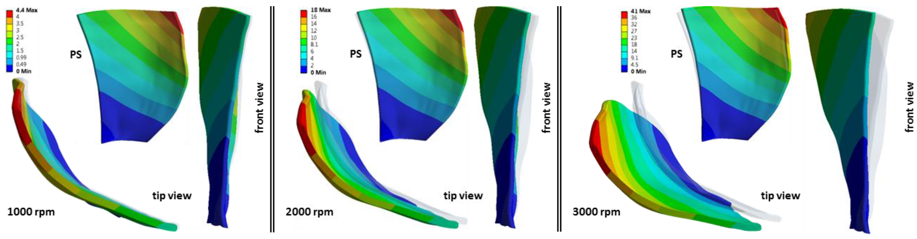
Figure 5 and
Figure 6 report the blade shapes according to the rotational velocity of the cooling fan for the non-activated and activated blade, respectively. In each picture, the original blade shape is displayed using a transparency frame in order to improve comprehension of the FEM results.
Figure 5 and
Figure 6 also show the contour plot that refers to the total blade deformation. From the blade shape analysis, it is possible to note that different fan rotational velocities determine a blade deflection according to the front view. The deflection increases with the fan rotational velocity and it is due to the blade structural stiffness close to the hub which cannot bear the centrifugal load. As can be seen in
Figure 5 and
Figure 6, the deflection due to the centrifugal load develops according to the circumferential direction and, for this reason, it is pointed out from frontal view. It should be noted that the blade shape modification, expressed by total deformation, develops on the blade-to-blade plane and thus, during the fan operation, it is not influenced by the centrifugal load that works in the actual blade operation. Conversely, the activation of the SMA strips affects the airfoil changes along the chordwise direction which is independent from the centrifugal load acting according to the blade height. A detailed analysis of the effects of both aerodynamic and centrifugal loads are reported as follows. The circumferential blade deflection implies an increment in the blade tip gap that is not considered in the present paper.
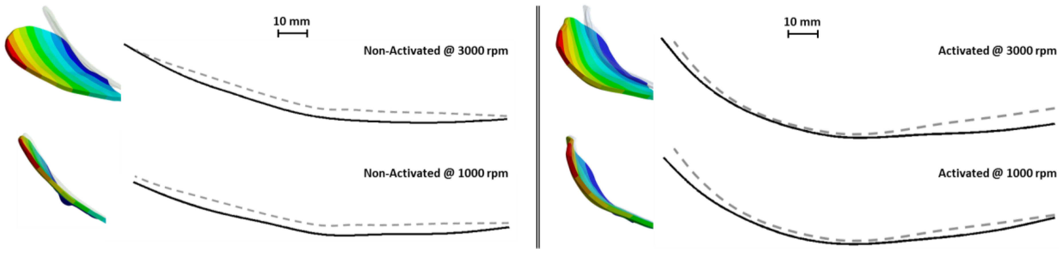
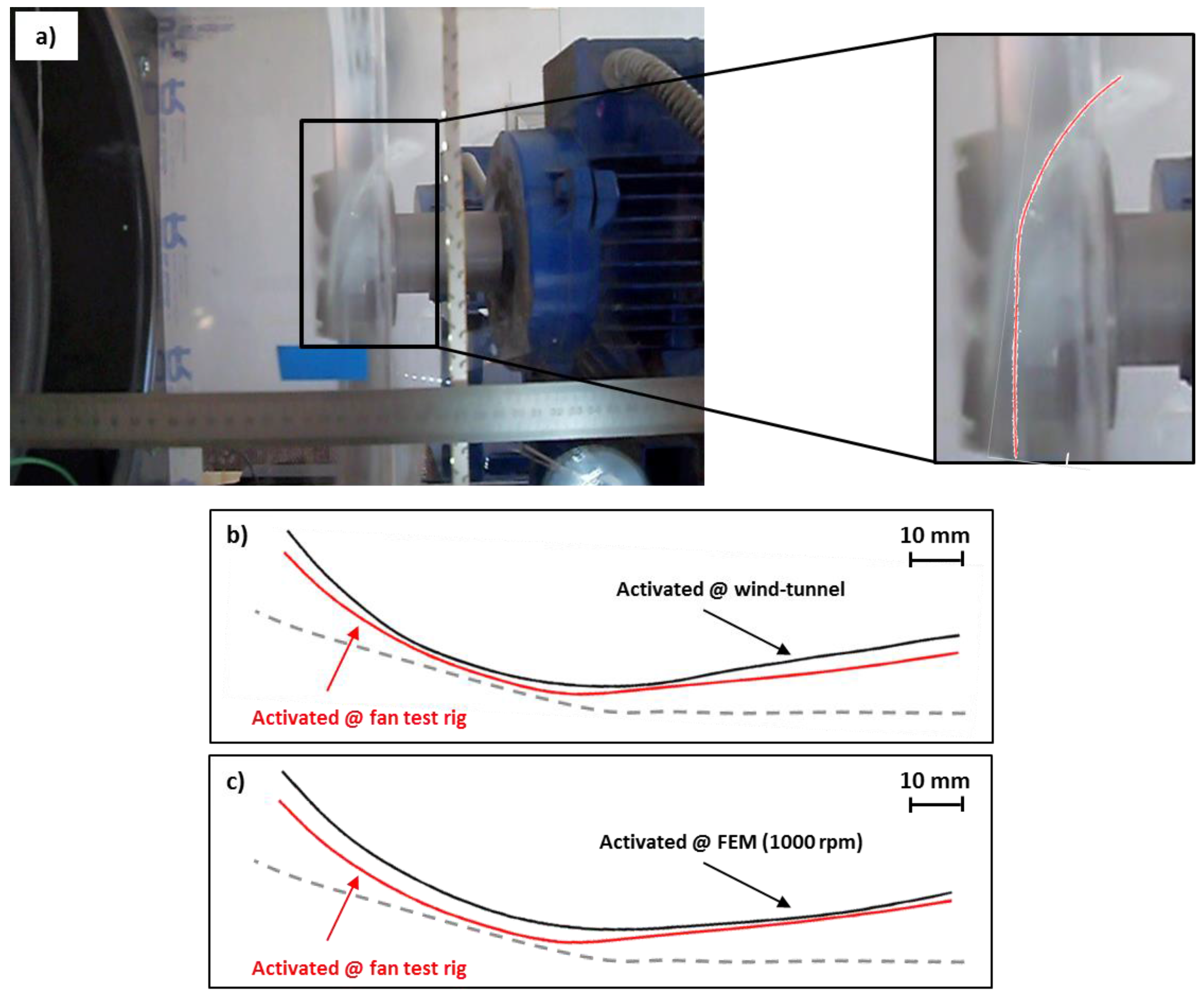
The effects of cooling fan operation on the blade tip shape were evaluated comparing the FEM results with the wind tunnel tests.
Figure 7 reports the comparison between the blade tip meanlines. Non-activated and activated meanline airfoil shapes were reconstructed from the blade tip view for both the FEM analysis (see
Figure 5 and
Figure 6) and wind tunnel test (see
Figure 2). In
Figure 7, the grey dashed lines represent the meanline airfoil shape of the blade tip taken during the wind tunnel tests, and therefore are not subjected to aerodynamic and centrifugal loads. The comparison of the blade tip meanline shapes shows that the loads provided by operation of the cooling fan (pressure and centrifugal force) do not determine a dramatic variation of the airfoil shape. The airfoil shape only appears lightly stretched at the highest rotational velocity, 3000 rpm, showing an increment in the airfoil chord value (especially in the case of the non-activated blade). The polymeric structure ensures proper resistance against these loads and allows the variation of the blade shape according to the action of the SMA strips.
5. Cooling Fan Experimental Characterization
In order to assess the performance of the cooling fan equipped with morphing blades, an experimental test was realized and the performance of the fan was measured. Since the blade shape represents the focus of the present research, the blade shape was monitored in order to establish the actual shape during the thermal ramp. A test rig was built for this purpose with a free-outlet configuration [
21], in accordance with the EN ISO 5801 standard.
The test rig was composed of a straight duct connected to the fan through a transparent section, which allowed detection of the blade shape. The cooling fan was driven by an electric motor equipped with an inverter. Since the fan outlet was open to the atmosphere, the total pressure rise produced by the fan was determined by measuring only the relative static pressure at the inlet. The fan volume flow rate Q was measured with a Pitot-static tube traverse according to the EN ISO 5801 standard. The air temperature was measured by means of a welded-tip thermocouple used to define the thermodynamic state of the air and control the heating and cooling ramp. An electric heater was positioned at the inlet section of the test rig to guarantee an adequate and controlled airflow temperature at the inlet of the cooling fan. A throttling valve was also installed at the inlet of the duct, allowing the fan operating point to be varied. Ambient conditions—i.e., pressure, temperature, and relative humidity—were recorded during experimental tests by means of a barometric station.
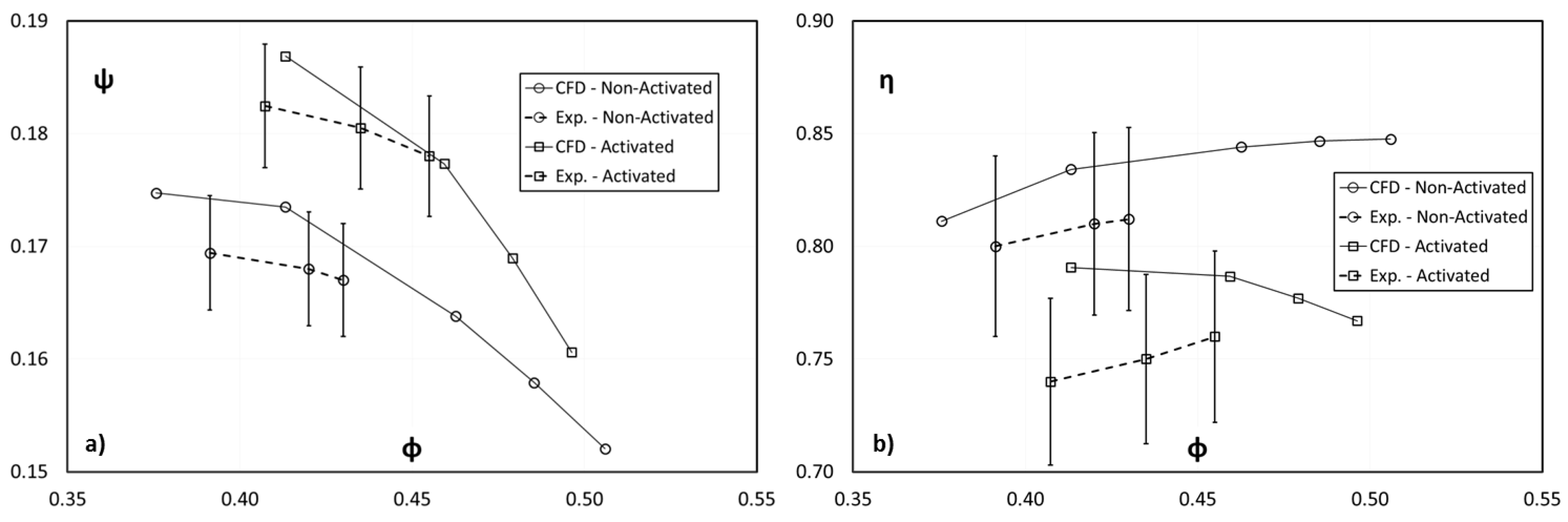
The experimentally measured fan performance was expressed in terms of flow coefficient ϕ, pressure coefficient ψ, and fan efficiency η as reported in
Figure 8 using dashed lines. In this preliminary test, the cooling fan was driven by an electric motor at up to 1000 rpm. Due to the experimental test configuration (free outlet with an electric heater at the inlet section), the fan performance curve is only available for lower flow rate values.
Figure 8 reports the experimental performance obtained in non-activated and activated conditions and the performance obtained by means of CFD simulations (taken from [
11]) for the same rotational velocity (1000 rpm).
Experimental values are reported with error bands of 3% and 5% for pressure coefficient and fan efficiency respectively (which are related to experimental accuracy but should not be used as a rigorous measurement of uncertainty) in order to set the variation between the CFD calculation and to judge the robustness of the numerical results. As can be seen, in the case of non-activated blades the CFD results are in good agreement, both in terms of absolute values and trends. In the case of activated blades, the absolute values are still in good agreement, while trends show less convincing agreement. This could be due to the uncoupled FEM-CFD simulation, which does not accurately take into account the mutual influence between fluid dynamics and deformation. Nevertheless, it is possible to state that the CFD results reflect the actual blade working conditions and the consequent pressure field used for the FEM analysis is representative of the actual blade structural load.
During the cooling fan performance test, the blade shapes were detected continuously thanks to the transparent section used near the fan.
Figure 9 reports a single frame and its reconstruction taken at the peak temperature reached during the heating ramp.
Figure 9a shows the captured frame, while
Figure 9b depicts the meanline shape of the blade tip reconstructed by a digital image post process and solid modeler reconstruction. Three blade tip shapes were superimposed. The first was the original blade tip shape taken before the wind tunnel testing, while the other two blade tip shapes refer to the activated conditions obtained during (i) wind tunnel test and (ii) the cooling fan test.
From
Figure 9b, it is possible to note that the two activated blades (wind tunnel and cooling fan test) show almost the same shape, with a variation of less than 2.5 mm. This value is considered negligible for the intended application if compared to (i) the repeatability of the thermomechanical treatment of the SMA strips and their insertion into the blade slots; (ii) the activation ramp provided in the fan test facility; (iii) the mechanical loads due to the pressure field and centrifugal action; and (iv) the accuracy of the recorded video and the subsequent solid modeler reconstruction.
Figure 9c reports the blade tip shape obtained from the FEM analysis. As shown in
Figure 9c, the deviation between the experimental blade tip shapes and the numerical one is very small, confirming the validity of the entire numerical analysis coupling the CFD and FEM numerical calculation. Using these analyses as a starting point, it will be possible to design and evaluate the performance of the cooling fan considering both fluid dynamic aspects and structural behavior. These findings are useful during the design phase, due to the complexity related to the design of SMA strips and thermomechanical treatment compared to the polymeric matrix stiffness [
11] and aerodynamic/centrifugal loads.
6. Conclusions
The present paper investigates the performance of a cooling axial fan equipped with morphing blades from a numerical and experimental point of view. Morphing blades were obtained using SMA strips embedded in a polymeric matrix. Exploiting the results of previous analyses related to (i) SMA strips and polymeric matrix characterization; (ii) thermal activation by means of a wind tunnel; and (iii) CFD analysis of the cooling fan, several structural analyses were carried out in order to discover the effects of aerodynamic and centrifugal loads on the blade shape.
Structural analyses were carried out by using a reconstructed blade shape obtained through the use of an innovative three-dimensional blade surface capture system provided by the Kinect sensor. This was able to detect the blade shape changes during the activation tests without altering the thermal and flow wind tunnel conditions. The results highlighted that aerodynamic and centrifugal loads provided by the operation of the cooling fan do not determine a dramatic variation of the airfoil shape. This demonstrates that (i) the wind tunnel blade shape characterization is suitable for analyzing the SMA blade shape modification; and (ii) the polymeric structure offers a proper resistance against these loads and allows variation of the blade shape according to action of the SMA strips.
A preliminary experimental characterization of the cooling fan was conducted using a purpose-built test-rig which allowed the evaluation of (i) the fan performance and (ii) the blade shape modification during thermal activation. Experimental data and numerical results are in good agreement both for fan performance and structural analysis.
The experimental approach (thermomechanical treatment and wind tunnel blade characterization) and the numerical model involved in the present research could be adopted for further investigations into SMA applications, in order to improve the efficiency and to increase the knowledge of these promising devices.


