Article

Application of a Novel Pseudo-Spectral Time-Marching Method to Turbomachinery †

by
Jesús Matesanz-García
* and
Roque Corral
School of Aeronautical and Space Engineering (ETSIAE), Universidad Politécnica de Madrid, Pza. del Cardenal Cisneros, 3, 28040 Madrid, Spain
*
Author to whom correspondence should be addressed.
This manuscript is an extended version of our paper published in the Proceedings of the 16th European Turbomachinery Conference (ETC16)—Turbomachinery, Fluid Dynamics and Thermodynamics, Hannover, Germany, 24–28 March 2025; paper No. 198.
Int. J. Turbomach. Propuls. Power 2025, 10(3), 19; https://doi.org/10.3390/ijtpp10030019
Submission received: 21 April 2025 / Revised: 6 July 2025 / Accepted: 21 July 2025 / Published: 6 August 2025

Abstract

A novel efficient method to evaluate time-periodic flows is applied to turbomachinery configurations in this paper (PSpTM). The technique reduces the overall computational cost of unsteady CFD calculations relative to conventional implicit approaches. The method is based on a pseudo-spectral definition of the time derivative rearranged in a time-marching fashion. The key advantage of this novel formulation compared with classical harmonic methods is that it requires minor modifications in the CFD solver structure. The method was implemented into an existing unstructured edge-based, second-order, compressible RANS solver. To benchmark the method, a well-established implicit time scheme based on a second-order backward implicit approach (BDF2) is used. Sample unsteady turbomachinery configurations are used to determine the accuracy and efficiency of the method. The accuracy of the solution is highly linked to the number of harmonics prescribed for the solution. An adequate level of accuracy was obtained while retaining a reduced number of harmonics, with approximately twice the number of harmonics of the unsteady perturbation. Notable savings in computational cost were observed when the PSpTM method was used with speed-up factors of between 2 and 10 with respect to the BDF2, depending on the case. However, the PSpTM method exhibits a poor periodic convergence rate, leaving room for further improvements in efficiency. However, even in its current form and with the current understanding, the method has a remarkable performance.

1. Introduction

Turbomachinery flows are inherently unsteady due to the different blade row interaction mechanisms. In these cases, applying conventional implicit time-marching Computational Fluid Dynamics (CFD) methods can be prohibitively expensive, because they require a significant number of time steps per period to accurately resolve the first harmonics of the time-periodic flow. Cyclic symmetry allows exploiting the temporal and the spatial periodicity of the problem to obtain notable reductions in computational cost.
A comprehensive review of Fourier methods for time and spatially periodic turbomachinery applications was provided by He [1]. As a gross simplification, time-periodicity is used to study the flow either in the frequency or time domain. Time-periodicity and cyclic symmetry (i.e., spatial symmetry) can be used to reduce the computational cost of both frequency- and time-domain methods. In time-domain methods, significant computational domain reductions can be achieved by using phase-shifted boundary conditions [2,3,4,5] in which a full wheel of blades is reduced to a single passage. Alternatively, the cyclic symmetry of the geometry can be used to Fourier decompose in space the gradual blade-to-blade variation of the flowfield by the Block Spectral Method (BSM) [6], also known as Passage Spectral [7]. When applied to turbomachinery, the method also captures flow instabilities and Tyler–Sofrin modes [7].
In these methods, the computational efficiency is linked to the reduction in the computational domain, which is limited by the number of blades ( N B ) and the number of spatial harmonics ( N H S ) captured in the solution: ( 2 N H S + 1 ) / N B . Hence, while significant benefits are expected for cases with an elevated number of blades, such as axial compressor and turbine stages where the N B is usually between 40 and 150; for other cases, such as fan analyses, where the number of blades is much lower (e.g., approximately 20), the potential savings are more limited.
Other commonly used approaches in turbomachinery are time-periodic methods based on the frequency domain. These methods can be classified into two main families: the Harmonic Balance (HB) approach, and the Linear and Nonlinear Harmonic Methods. In the latter, a harmonic perturbation is defined by a Fourier series and superimposed to the mean flow. Linear frequency-domain Reynolds-Averaged Navier–Stokes (RANS) methods compute the nonlinear steady-state base flow first and then derive the linearized RANS equations in the frequency domain. This method disregards the interaction between the mean flow and the perturbations [8,9,10]. This approach has been widely used in aeroacoustics and aeroelastic analyses in turbomachinery during the last two decades.
In recent times, nonlinear frequency domain methods have been developed. Ning and He [11] proposed an approach to couple the nonlinear mean flow and the linearized perturbations. This was named the NonLinear Harmonic (NLH) method. Later, the NLH method was generalized by Wang and di Mare [12] and named Favre-averaged NLH (FNLH), delivering a more rigorous relation between the mean flow and the harmonic perturbations. One key limitation of the NLH methods is that they require the development of a dedicated linearized frequency-domain Navier–Stokes solver as part of the algorithm, where the unknowns are the harmonic coefficients of the variables. Implementing such models in conventional implicit CFD solvers requires a notable effort.
The other family of frequency-domain methods is the Harmonic Balance (HB) approach. In the HB, the time derivative is Fourier transformed and defined as a high-order finite-difference discrete operator that couples several time instants of the solution [13,14,15]. A key advantage of the technique is that the temporal discretization has spectral resolution. However, this comes at the cost of simultaneously computing several time instants. Due to this factor, these methods are also known as time spectral methods (TS). In the authors’ opinion, this nomenclature better defines the nature of the problem, and it is used to name the novel method in this work.
With either the NLH or HB/TS methods, the number of harmonics, N H , of the solution must be prescribed a priori. This results in the coupled solution of a system of nonlinear equations 2 N H + 1 times larger than the original unsteady problem. Thus, an increase in computer memory is required for these methods. However, they can provide significant computational cost benefits by directly achieving the time-periodic solution, and averting the time-accurate simulation of the initial transient prior to the final periodic state. In internal aerodynamic problems, the advantages of using harmonic methods are larger than in external aerodynamic problems since the spatial cyclic symmetry of the problem can be exploited along with the time-periodicity. Furthermore, harmonic methods have higher accuracy than implicit time-marching methods for periodic flows because the time discretization is exact. Hence, the number of time instants per period is significantly reduced while the accuracy of the simulation is maintained. However, the major practical drawback of the harmonic methods is that they require a tailored and convoluted implementation into existing CFD solvers. This is an important obstacle that limits a more widespread adoption of such methods.
Harmonic Balance methods require efficient approaches to resolve the resulting system of coupled equations. Commonly used implicit-solving techniques, such as the dual time step, are applied for this purpose. Different implicit solving techniques were evaluated by Thomas et al. [16], Woodgate and Badcock [17], Su and Yuan [18], and more recently by Frey et al. [19]. In these approaches, the future and past physical time instants are coupled by the HB/TS formulation. As a consequence, the contribution of the coupling matrix among different time instants to the Jacobian of the residuals needs to be retained to derive stable methods [19,20]. Thus, depending on the approach selected to reduce the full Jacobian, some stability limitations can be found.
This work simplifies the formulation of the HB by computing a single instant at a time instead of multiple time instants simultaneously, as in the classical HB method. Then, using the previous time instants, a novel implicit time-marching formulation is proposed for the time spectral method. Finally, the implicit formulation is converged in pseudo-time (DTS) for each time instant. This approach decouples the spectral derivative and removes the stability limitations of the implicit DTS. This novel method, named Pseudo-Spectral Time-Marching (PSpTM), provides a straightforward pseudo-spectral formulation of the time derivative that can be used in generic CFD solvers with minimal modifications. This approach was first proposed by Matesanz-Garcia and Corral [21].
This formulation also allows the preconditioning of the dual time step to accelerate the implicit convergence in pseudo-time. Based on the problem’s time-periodic formulation, an acceleration of the time step convergence is proposed through a modification in the dual time step (DTS) technique. Contreras and Crespo [22] proposed to use the previous period’s information to initialize the DTS and accelerate its convergence to the periodic state. This period-informed approach is crucial to maximize the computational savings derived from this novel pseudo-spectral method.
In this work, the Pseudo-Spectral Time-Marching approach is evaluated for the first time for turbomachinery applications. Sample unsteady quasi-2D annular configurations are used to determine the viability of the method. To benchmark the method, the well-established time second-order backward implicit finite-difference approach (BDF2) is used. The new approach and the baseline are compared in terms of accuracy and computational cost to illustrate the efficiency of the new method.

2. Methodology

2.1. Harmonic Balance or Time Spectral Formulation

The Pseudo-Spectral Time-Marching (PSpTM) method relies on the assumption of time-periodic flow, a common case in turbomachinery flows. For time-periodic cases, the time derivative can be defined as pseudo-spectral derivative based on a truncated Fourier series. This pseudo-spectral derivative provides spectral accuracy for a prescribed fundamental harmonic and its higher harmonics of the solution. In order to introduce the PSpTM method, the Harmonic Balance (HB) or time spectral (TS) method is introduced first. The semi-discrete form of the Reynolds-Averaged Navier equations on a fixed grid is used to define the method. This is written in compact form as:
d u d t = R ( u )
where u is the vector of unknowns that contains the solution in all the mesh points, and R ( u ) the residual that contains the discretization of the spatial operator. The Equation (1) is a nonlinear Ordinary Differential Equations (ODEs) system. The method described here could be applied to any discrete system of Partial Differential Equations (PDEs).
The discrete Fourier transform in time of the solution is
u ^ k = 1 N n = 0 N 1 u n e I k 2 π T n Δ t
where the time period T is divided into N time intervals, and k is the harmonic index. In the TS and the PSpTM, with just one fundamental frequency, the period and the number of intervals fix a time step of size Δ t = T / N . In these methods, the number of time steps is defined by the number of harmonics of the fundamental frequency, N H , that are included in the discrete time derivative. This sets the number of steps per period to N = 2 N H + 1 .
In periodic problems with a known frequency, an analytical expression of the time derivative can be obtained from the coefficients of the truncated Fourier series, u ^ k . The temporal discretization of Equation (1) at the time instant n in general is
( D t u ) n = R ( u n )
where D t t represents the discrete form of the temporal derivative. The spectral discretization of operator D t can be written as:
D t u n = 2 π T k = N 1 2 N 1 2 I k u ^ k e I k 2 π T n Δ t
where the summation involving the Fourier coefficients u ^ k can be rewritten for the HB or TS method in terms of the physical variables as [15]
( D t u ) n = m = N 1 2 N 1 2 d m u n + m
where the weight coefficients, d m , of the series are
d m = π T ( 1 ) m + 1 cos ec m π N if m 0 0 if m = 0
In the HB/TS method, the operator D t is anti-symmetric and centered in the n-th step. Furthermore, in the HB method, the operator couples the future N H time steps with the N H previous steps. The method is exact if all the harmonics are retained. In the HB/TS, the time derivative couples N time instants, which must be solved simultaneously. Analogously to the dual time step (DTS) method, introducing the pseudo-time, τ , the system of equations (3) can be marched in the pseudo-time τ to the steady state solution Q = { u n N H , , u n 1 , u n , u n + 1 , u n + N H } T formed by the N equally spaced instants of the period,
P 1 Q τ = D t Q + R T S ( Q ) .
where
R T S ( Q ) = { R ( u n N H ) , , R ( u n ) , , R ( u n + N H ) } T
is a new residual containing the residuals at all the time instants. The coupling among all of the sets of equations is due to the D t operator associated with the physical time derivative, which is a full block circulant matrix with only N independent elements. The D t Q acts as an additional source term for the DTS. The preconditioning matrix P 1 is included to represent the acceleration to the steady-state strategies of the solver of choice.
The simultaneous evaluation of N time steps requires a rise in the memory requirements of the method compared with a conventional time-marching implicit scheme. However, in most cases, a trade between computational cost reduction and an increase in memory is expected. The main challenge for the TS or HB methods is the notable code restructuring required to enable the solution of multiple time steps or to take advantage of a computational domain reduction in turbomachinery cyclic periodic problems. Time spectral methods are significantly more complex to implement in current CFD solvers than a conventional implicit approach, such as BDF2. Moreover, harmonic methods formulated in the frequency domain must converge the individual harmonics separately and, in the authors’ experience, can present convergence problems in complex flows prone to fluid dynamic instabilities.
The implicit formulation of the HB/TS approach through a dual time-step (Equation (7)) can also bring up some limitations. The explicit solution of the dual time step is limited by the CFL number of iterations in pseudo-time. This normally requires a high number of iterations to converge. For this reason, implicit formulations of the DTS have been proposed to increase the CFL and reduce the convergence requirements. However, implicit methods require adding the contribution of the spectral temporal derivative ( D t Q )to the Jacobian matrix. This adds complexity to the implementation of these approaches in existing implicit codes. For this reason, some reformulations have been proposed to evaluate the additional contributions of the source term implicitly and explicitly [16,17,18,19,20]. However, this can bring up additional considerations on the stability of the DTS scheme.

2.2. Pseudo-Spectral Time-Marching Method

To address the challenges derived from the TS and HB methods, the Pseudo-Spectral Time-Marching (PSpTM) method is proposed. Unlike the TS or HB method, where all the time instants of the D t operator are computed simultaneously by a DTS or any other iterative method (see Equation (7)), the PSpTM method employs an implicit time-marching approach to calculate the solution at time instant n + 1 ( u n + 1 ) as a function of the known 2 N H previous time steps and the residual at that time step ( R ( u n + 1 ) ), i.e.,
u n + 1 = Ͱ   ( u n , u n 1 , , u n 2 N H , R ( u n + 1 ) )
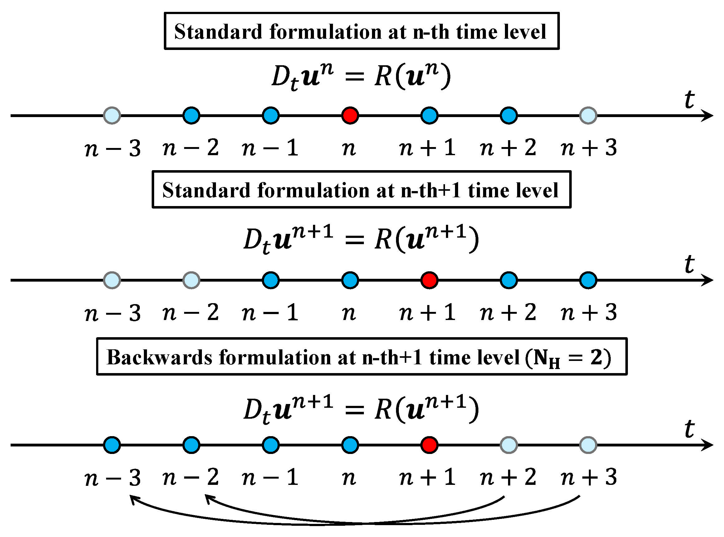
This results in a nonlinear system of algebraic equations. For the HB method, the discrete operator D t was expressed in Equation (5) in anti-symmetric form around the time instant n, including all the time levels comprised between n N H and n + N H . However, in the PSpTM method, the discrete-time derivative is one-sided. This is achieved in two steps as sketched in Figure 1. First, the time derivative is evaluated at the time instant n + 1 instead of n , similarly to an implicit method. This results in a simple shifting of the indices in Equation (5). Second, the time-periodicity of the problem is used to re-formulate the operator. The time instants in the future are assumed to match previous time steps, so the new formulation is comprised between n + 1 2 N H and n + 1 (Figure 1). With this formulation, the 2 N H previous time instants are employed to compute the time derivative at t = ( n + 1 ) Δ t as:
( D t u ) n + 1 = p = 1 2 N H d p u n + 1 p = R ( u n + 1 )
where the weighting coefficients are rearranged as
d p = π ( 2 N H + 1 ) Δ t ( 1 ) p csc p 2 N H + 1 π
It is important to emphasize that d 0 = 0 . Hence, the time derivative at t = ( n + 1 ) Δ t does not depend on u n + 1 .
The PSpTM formulation assumes the time-periodicity of the problem. While the time-periodic solution is the aim of these analyses, the transient stage from the initialization to the time-periodic solution is not periodic. Thus, the initial transient computed by the method is not accurate since the time derivative is not consistent for arbitrary time signals, but has spectral accuracy for the final time-periodic solution.
The resulting scheme can be written as
P 1 w τ + p = 1 2 N H d p u n + 1 p = R ( w ) .
where a dual time step (DTS) method is used to converge the nonlinear system of equations. In most applications found in the literature, the initial condition for the DTS is w ( 0 ) = u n , and the system is marched in the pseudo-time τ until the steady-state is reached. When τ , the pseudo-time derivative converges to zero, w / τ 0 . Hence, w u n + 1 . Given that d 0 = 0 , the temporal derivative does not contain implicit terms, and ( D t u ) n + 1 is a constant based on the previous time steps that is added to the residual of the system ( R ( w ) ). In contrast to similar-looking implicit solving approaches for the HB/TS technique [16,17,18,19,20] that couple all the temporal terms in the solution, the evaluation of the additional spectral term as a constant only simplifies the implementation of the method. No additional terms are derived from the dual-time-step solution, and the constant source term means that the stability of the DTS is not affected by the temporal derivative. This facilitates the convergence to the steady problem in pseudo-time for each time step. Further comments on stability are provided in Section 2.3.2.
Also, compared with the TS or HB formulation, this approach is less memory demanding. The 2 N H time steps must be stored in memory, but the residuals are stored for a single time step only. Thus, the computational cost per iteration is 1 + 2 N H times lower than in the HB method. The PSpTM also has a more straightforward implementation into any existing implicit CFD solver than other harmonic methods, because only a modification of the time discretization method is needed. Moreover, in the PSpTM method, the time-periodicity of the problem can be exploited to accelerate the dual-time-step convergence by using the information derived from previous periods. This is explored in the following section.
Another advantage of using a time-marching implicit formulation for the time-periodic problem is that the potential benefits in computational cost can be complemented with other methods that apply the cyclic periodicity of the problem to reduce the computational domain. For example, the Block Spectral Method [6,7] and the phase-shifted boundary conditions [2,3,4,5].

Period-Informed Dual Time Stepping

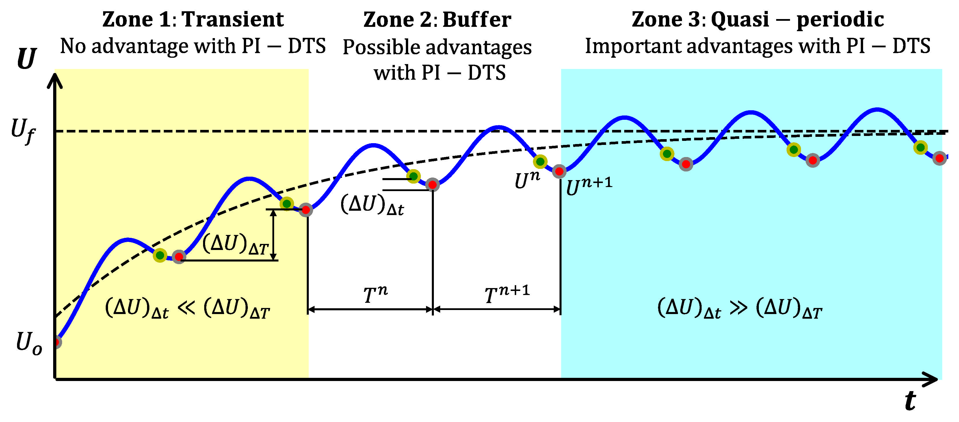
The convergence speed of the dual-time-step approach is heavily dependent on the initial value of w used. Fewer pseudo-time iterations are needed to achieve an equivalent accuracy when the initial solution is closer to the final converged result. With this idea, Contreras and Crespo [22] proposed a modification of the DTS for time-periodic problems. Conventionally, the previous physical time step ( w ( 0 ) = u n = u ( t Δ t ) ) is used as the initial value for the DTS. Without any additional information, this is considered the closest guess to the value in the next step. However, in time-periodic problems, once the solution approaches the final periodic state, the corresponding solution in the last period ( u ( t T ) ) becomes a much closer initial guess than u ( t Δ t ) as shown in Figure 2. Contreras and Crespo [22] observed significant reductions in computational cost through this approach in different time-periodic turbomachinery CFD problems using a second-order backward difference (BDF2) implicit scheme.
In the case of the PSpTM method, the advantages derived from this approach become more significant than in the BDF2, since the time step is much larger than in a conventional implicit solver. Hence, the difference between the next time step and the previous step, ( Δ u ) Δ t , becomes much larger compared with the difference in the solution between periods, ( Δ u ) Δ T . Thus, for the application of the PSpTM method, the periodic-informed dual time step (DTS-PI) is necessary to take full advantage of the computational cost reduction.

2.3. CFD Solver

The method was implemented in an edge-based, second-order finite-volume, unstructured, unsteady, compressible, viscous CFD solver known as HADES [23,24]. In the base solver, the semi-discrete system of equations is marched in time implicitly by a second-order backward difference scheme (BDF2):
P 1 Ω u τ + 3 ( Ω u ) n + 1 4 ( Ω u ) n + ( Ω u ) n 1 2 Δ t = R ( u n + 1 )
The solver can handle moving meshes to perform fluid–structure interaction for aeroelastic applications by including the element volume, Ω , variation in the time scheme, as well as the element face velocity in the convective terms. The code has been successfully used to predict non-synchronous forced response in fans due to the intake separation and flutter analyses under distorted flows [25,26]. The solver solves the Reynolds-Averaged Navier–Stokes equations with the standard Spalart–Allmaras as turbulent closure model [27], though a fine-tuning of the turbulence model for turbomachinery has been carried out [24].

2.3.1. Time Integration Scheme

The Pseudo-Spectral Time-Marching (PSpTM) method can be expressed as:
p = 1 2 N H d p ( Ω u ) n + 1 p = R ( u n + 1 ) .
The solution of the nonlinear system of equations in u n + 1 is obtained using a DTS approach:
P 1 Ω u τ + p = 1 2 N H d p ( Ω u ) n + 1 p = R ( u n + 1 )
which is solved using Newton–Jacobi iterations [28]. Local time-stepping preconditioning is used to accelerate the convergence. Linearizing the residual R about the m -th iteration, R m + 1 = R m + ( R / u ) m ( u m + 1 u m ) and discretizing, u / τ = ( u m + 1 u m ) / Δ τ , Equation (15) can be written as
P 1 Ω m + 1 Δ τ R u m Δ u m + 1 = R m p = 1 2 N H d p ( Ω u ) n + 1 p
where Δ u m + 1 = u m + 1 u m . Equation (16) is a sparse linear system of equations that is solved using a Jacobi method. To improve the convergence of the method, the Jacobian is approximated by the corresponding to a first-order discretization of the convective terms ( R / u ) ( R / u ) 1 st-order . In classical HB/TS formulations, the additional terms added to the residual are not constant. Therefore, they must be added to the Jacobian for the implicit evaluation of the method. Thus, a significant advantage of the PSpTM method is that its implementation does not require modifying the Jacobian formulation.
The only contribution of the PSpTM method is a constant forcing term due to the 2 N H previous time steps of the time derivative. Thus, the DTS implementation is even simpler than the baseline BDF2 method. This is one of the method’s main advantages compared with other time spectral or Harmonic Balance methods, whose implementation is significantly more complex, since a modified Jacobian formulation is required for the implicit analysis. The PSpTM method only requires a minor modification of the time discretization without restructuring the solver structure.

2.3.2. Stability of the Method

Unlike the standard HB formulation, the PSpTM approach uncouples the spectral time derivative from the future time instants using solely past time solutions, as in a classical time derivative. Moreover, the solution at the time instant ( n + 1 ) Δ t does not appear in the time discretization. Thus, when the dual-time-step (DTS) method is employed to solve the resulting system of nonlinear equations (Equation (15)) the implicit spectral derivative is just a constant source term. Therefore, the time spectral derivative does not modify the stability of the original system of Equation (16).
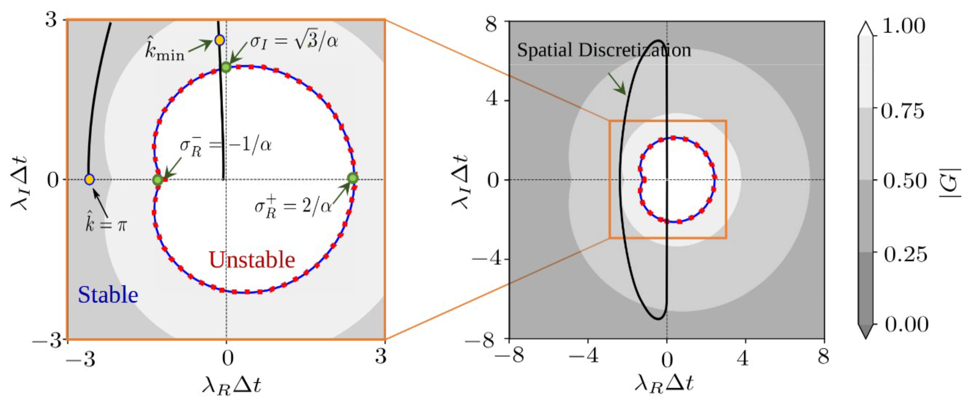
The implicit baseline temporal scheme (Equation (10)) is conditionally stable as shown by Matesanz-Garcia and Corral [21]. Further comments on the derivation of the method’s stability are summarized in Appendix A. The gain function, G, is determined by a polynomial of degree 2 N H . For a single harmonic, N H = 1 , the characteristic polynomial reduces to
( λ Δ t ) 3 s i n ( π / 3 ) π G 2 + G 1 = 0
where λ = λ R + I λ I is the footprint of the spatial eigenvalues. Assuming that the dissipation is properly set, the stability condition is
| λ I Δ t | = C F L sin ( k ^ ) 2 π 3
where the CFL number is ( u 0 + a 0 ) Δ t / Δ x , and k ^ = k Δ x the reduced wave number. The scheme is unstable for very small wave numbers; it is derived analytically and numerically that unstable waves leave the domain before reaching a significant amplitude (Appendix A).

2.3.3. Unsteady Boundary Condition

To trigger the unsteadiness of the flow in all the cases studied in this work, an unsteady boundary condition is used at the inlet plane of the domain based on a static pressure traveling-wave perturbation
p θ , t = p ¯ 1 + A sin 2 π f r o t t k θ ˜
where p ¯ is the average static pressure at the inlet, A is the dimensionless amplitude, and f r o t is a reference frequency that is determined by the rotational speed of the stage. The spatial variation is characterized by the azimuthal coordinate, θ , which is normalized by the circumferential pitch of the sector, θ ˜ = ( θ θ m i n ) / ( θ m a x θ m i n ) . The parameter k N defines the wavelength of the perturbation as a nondimensional wave number. The temporal term is controlled by a prescribed reference frequency, in this case, the fan rotation frequency, f r o t .

3. Application to Time-Periodic Flows in Turbomachinery

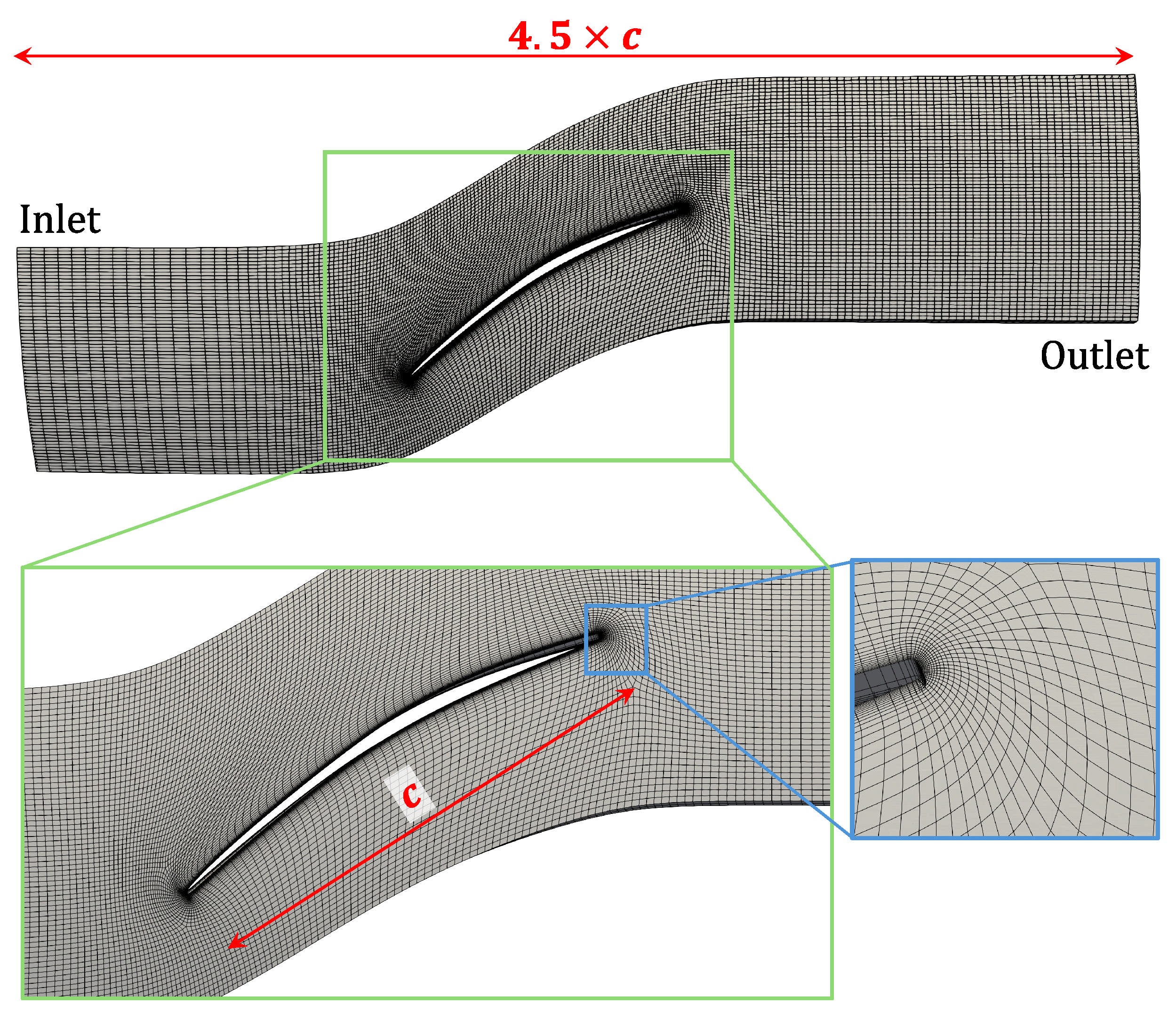
As the reference case for this work, the ACAT fan blade tested in AneCom AeroTest [29] and extensively employed by the UPM turbomachinery group for aeroelastic and noise analyses [25,26] is used. The blade is isolated from the intake and the remainder of the stage for this test. The main characteristics of the blade are summarized in Table 1. This configuration has 20 blades. To simplify the test of the present work, a quasi-2D annular approximation of the geometry is used. For this purpose, a radial section of the ACAT rotor 1 blade is taken at approximately 60% of the blade span. The operating point is based on sea-level static conditions from the experimental reference.
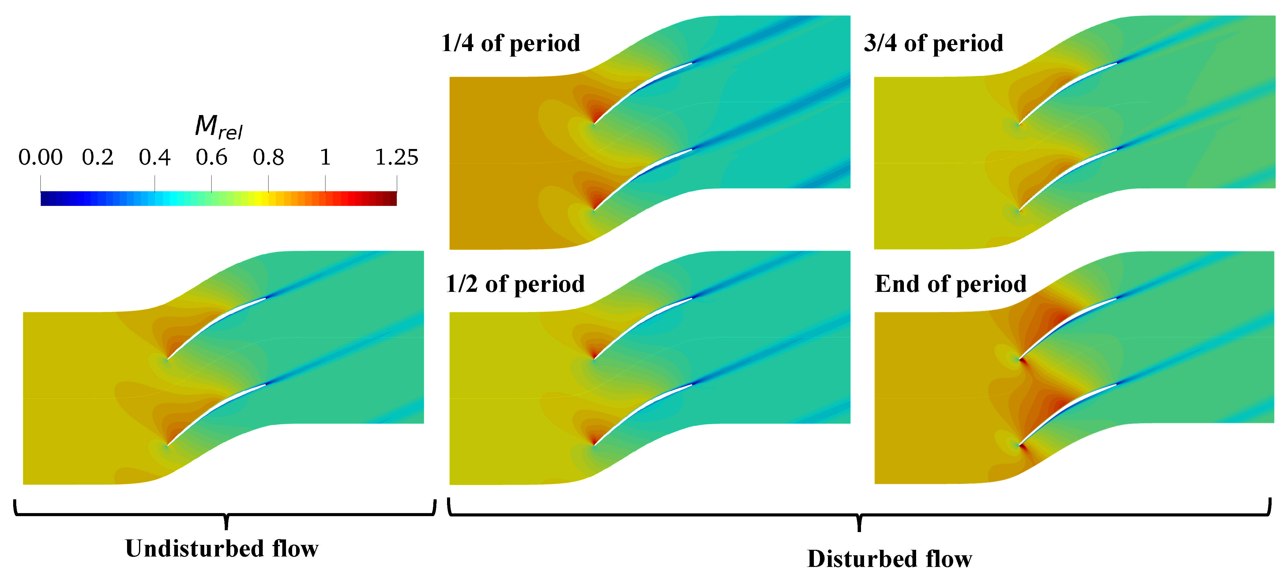
Two configurations are used in this work based on the reference geometry: a single-passage configuration (Figure 3), and a full annulus configuration. In both cases, Riemann boundary conditions are used at the inlet of the domain. The reference velocity, static pressure, and static temperature are imposed at the inlet based on a 3D configuration defined by Chennuru et al. [25]. In this case, a 3D configuration with an axisymmetric intake design was evaluated at take-off conditions with no crosswind. Static pressure is fixed at the domain exit. The inlet Mach number of the section is M r e l , i n = 0.63 . In the single-passage configuration, periodic boundary conditions are imposed at the lateral sides of the blade passage. Viscous adiabatic walls are applied to blade surfaces. The top and bottom parts of the domain are modeled by symmetry boundary conditions. Spalart–Allmaras with wall functions is used as the turbulence closure model for this configuration. A y + of between 30 and 100 is set for all the surfaces. A total of 35,000 nodes are used per passage. The fan operational speed is fixed to 70% of the maximum fan speed. The Reynolds number for this case is approximately 1.6 × 10 6 . In all cases of this study, the flow is initialized from an undisturbed base flow field obtained by steady RANS computation (Figure 4). The different cases evaluated in this work, and their respective CFD setups are summarized in Table 2.

3.1. Low-Frequency Application: Single Passage with Static Pressure Perturbation

As an initial case to demonstrate the applicability of the PSpTM method to transonic turbomachinery design, a low-frequency static pressure uniform perturbation at the inlet is proposed for a single-passage domain (Case A in Table 2). This results in a wave perturbation at the inlet, with wave number k = 0 . The fundamental frequency of the perturbation is equal to the fan rotation frequency. This results in a Strouhal number of approximately S t = f c / V inlet 0.05 . The amplitude of the perturbation is set to 10% of the reference inlet static pressure. This results in notable variations on the aerodynamics of the blade section (Figure 4), with nonlinear phenomena such as shock waves migrating from the pressure to the suction side during the period of the perturbation. This case is intended to mimic a pressure perturbation created by the intake’s nonaxisymmetric geometry. In these cases, the local geometry changes result in a quasi-steady, low engine order, azimuthal variation of the static pressure along the intake duct. This perturbation becomes unsteady in the fan domain with the fan rotation as the fundamental frequency. The perturbation has been exaggerated to demonstrate the method’s capabilities. The PSpTM method is applied with an increasing number of harmonics in the solution, with N H = 1 , N H = 2 , and N H = 3 . The BDF2 method is used to benchmark the PSpTM method.
For the BDF2 approach, 100 time steps are used per fundamental period with the aim of capturing events of higher frequency. To obtain an equivalent level of convergence, the BDF2 method is set to have 20 and 40 Newton and Jacobi inner iterations per physical time step, respectively. The maximum CFL for the implicit DTS scheme is set to 50. The case is run for 25 fundamental periods to evaluate the system convergence. To benchmark the PSpTM method, it is necessary to guarantee an appropriate level of accuracy in the time solution. This convergence strategy was selected from different combinations to obtain sufficient time convergence in the solution for a reasonable computational cost. In many industrial applications, a much lower number of internal iterations is normally used. However, this can result in a notable reduction in time accuracy, despite achieving periodic convergence. Hence, to enable an adequate comparison between the BDF2 and the PSpTM approach, a highly converged temporal solution is used.
As defined in the previous section, in the PSpTM method, the number of time steps required per period is a function of the number of harmonics of the solution. Thus, the number of time steps will change for each of the four values of N H of this test. Due to the DTS-PI (Section 2.2) approach [22] in the PSpTM method, the PSpTM method ends requiring fewer internal iterations in the DTS to achieve the required convergence level. This contributes substantially to the reduction in the computational cost of this method. For this reason, for the current case, the number of inner iterations was set to 5 and 25 for the Newton and Jacobi iterations, respectively. This results in a much lower cost per time step than the BDF2 method. The maximum CFL for the inner iterations is set to 50.
To compare the accuracy of the PSpTM method with the BDF2 approach, the mass-weighted average of the total pressure at the outlet plane is used. The total pressure is scaled as a total pressure ratio with the time average of the total pressure value at the inlet (Figure 5). The PSpTM method only requires a few temporal time steps per period, so it is not simple to directly observe the temporal evolution of the variables. The temporal derivative of the PSpTM method is based on a harmonic series. Thus, to adequately visualize the temporal evolution of the solution, a Fourier series fitted for the fundamental frequency and the number of harmonics is included based on the actual values at each time step (Figure 5).
Given the amplitude of the inlet perturbation, the temporal variation of the flow is mostly defined by the first harmonic of the solution of the PSpTM method. Second-order contributions of the higher harmonics are present due to the flow nonlinearities, such as shock waves. The accuracy of the PSpTM method increases progressively with the number of harmonics included in the solution (Figure 5). However, after retaining two harmonics, the gains in accuracy are marginal. In order to further illustrate this, a Fourier transform (FT) is applied to the temporal variation of the mass weighted value of the total pressure ratio at the outlet for both the BDF2 and the different PSpTM method (Figure 6). As mentioned, the accuracy of the predicted amplitude of the method increases with the number of harmonics. The first harmonic contains most of the amplitude of the solution, with a second-order contribution from the second and third harmonics.
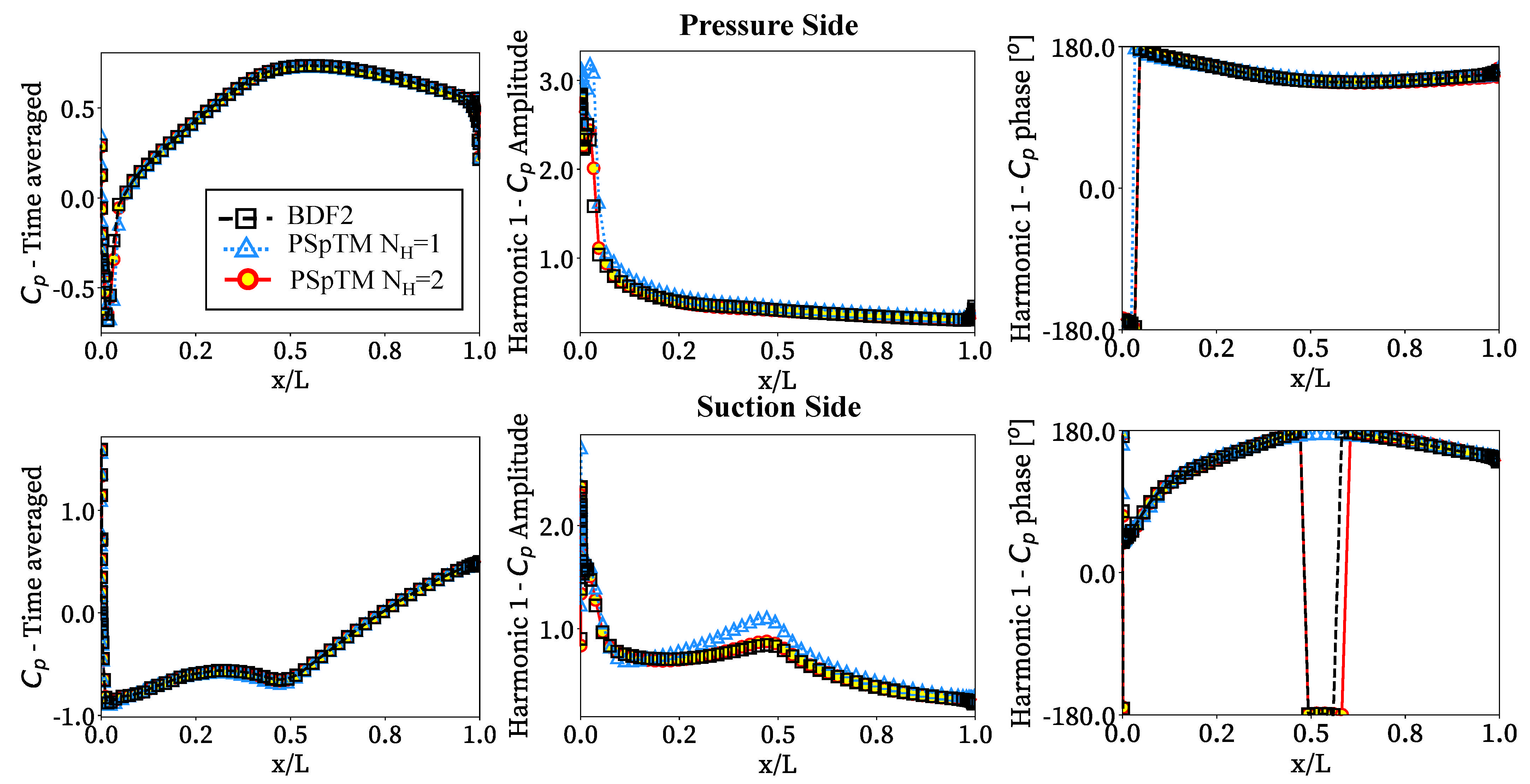
Figure 7 compares the time average and the amplitude and phase of the first harmonic of the pressure coefficient, C p , along the blade to assess the PSpTM’s capability to capture the local flow variations over time. Since no notable variations were observed between the N H = 2 and N H = 3 solutions of the first harmonic, only the N H = 2 case is included. Overall, the PSpTM method has adequate agreement with the BDF2 baseline in the time-averaged pressure distribution. The method can also capture some flow nonlinearities, such as the shock waves emerging near the leading edge in both the pressure and suction side and given time instants (Figure 4). The shock wave at the pressure side also reaches the suction side of the contiguous blade around half of the chord. Some discrepancies are observed between the BDF2 and PSpTM in the amplitude of the first harmonic when only a single harmonic is retained ( N H = 1 ). These are more noticeable on the leading edge of the pressure side and around the center of the blade chord of the suction side. These two regions of uncertainty are the result of the same shock wave that expands through the blade passage (Figure 4). That shock blocking the passage triggers higher harmonics on the flow that the case with N H = 1 cannot accurately capture. Nevertheless, the cases with a higher number of harmonics correctly include the effects of the shock wave and other second-order effects. Finally, some differences are observed in the solution phase for both harmonics. However, the general distribution of the first harmonic phase is properly captured with both cases in the PSpTM. Thus, the method can accurately capture the main flow unsteadiness over the blade.
Once the accuracy of the PSpTM method has been addressed, it is necessary to compare the performance of the PSpTM method with the reference BDF2 approach. For this purpose, the periodic norm
Ψ ( ϕ ) = 1 N n o d e s 1 ϕ r e f 2 j = 1 N n o d e s ( ϕ j ( t ) ϕ j ( t T ) ) 2
is used: In this case, the periodic norm of the static pressure, ϕ = p , nondimensionalized with the isentropic dynamic head at the exit, ϕ r e f = P ¯ 0 , i n p ¯ e x i t , is evaluated in the whole domain. Figure 8 displays the periodic norm as a function of the number of periods, time steps, and the overall computational cost required for convergence. The CPU time unit is defined as the actual time multiplied by the number of CPU cores used in the simulation, which is an approximation of the computational time in a serial machine.
Figure 8a shows that the PSpTM method requires substantially more periods to achieve a periodic convergence than the BDF2 approach. However, this slow convergence rate does not result in a significant penalty in the number of time steps required to achieve periodic convergence (Figure 8b). This is due to the much lower number of time steps required per period in the PSpTM method. One of the key advantages of the PSpTM is that it requires fewer inner iterations to achieve a similar level of convergence per time step than conventional approaches such as the BDF2 method. This significantly reduces the overall computational cost by a factor of ~4 for the N H = 1 case, and approximately 2 and 3 for the N H = 3 and N H = 2 cases, respectively. Despite that, the slow convergence of the PSpTM could have some negative implications for more complex cases.
One potential contributor to the slow convergence rate on the PSpTM is believed to be the initialization. The solution is started from a converged steady simulation. This initialization is set equal to the 2 N H previous steps of the method. Thus, while the unsteady conditions are established during the initial transient, the PSpTM method is still far from a periodic solution. Thus, the additional source term has not yet been set properly. For this reason, the method requires additional periods to smoothly transition to the time-periodic solution. Further studies are required to optimize the PSpTM method’s convergence and increase the overall computational gains. A potential fix for this would be the application of a hybrid method with a BDF2 initialization. This initialization should have sufficient time steps to capture some of the first flow harmonics with moderate accuracy. This should also last enough to reach a quasi-periodic state to cancel out any non-harmonic contribution of the initial transient. The pertinent time steps would be introduced on the PSpTM solution. Future work is required to analyze the impact of this strategy.

3.2. High-Frequency Case: Rotor/Stator Potential Interaction

A rotor/stator potential interaction case is emulated with the ACAT B1 domain as an additional test using the single-passage domain (Case B in Table 2). Although in this case the stator is excluded, a similar problem can be formulated by adding a sinusoidal pressure wave at the domain inlet of k = 1 with a fundamental frequency equal to the blade passing frequency. In normal conditions, the potential perturbation would be downstream of the rotor. However, given the dimensions of the domain, the potential perturbation could be cut off. Thus, for this case, the potential perturbation was moved upstream to demonstrate the method’s capabilities. This is analogous to an EO20 problem, and it is used to test the method at high frequencies ( S t = 1 ). The amplitude of the perturbation is set to 5% of the reference inlet static pressure.
The convergence strategy of both the BDF2 and the PSpTM methods was adjusted to this case. For the BDF2 approach, 100 time steps are used per fundamental period to capture events of higher frequency and obtain a good temporal resolution for comparison purposes. To obtain an equivalent level of convergence, the BDF2 method is set to have 30 and 50 Newton and Jacobi inner iterations, respectively. The maximum CFL for the implicit DTS scheme is set to 50. The case is run for 25 fundamental periods to evaluate the system convergence. The PSpTM method is conditionally stable (Appendix A), with some stability restrictions when modes with frequencies lower than the fundamental frequency of the problem are present in the problem. For this reason, at higher frequencies, it is advisable to apply a more conservative convergence strategy. For the current case, the number of inner iterations was set to 5 and 30 for the Newton and Jacobi iterations, respectively, to increase PSpTM’s stability. This results in a much lower cost per time step than the BDF2 method. The maximum CFL for the inner iterations is set to 15. Each PSpTM case is run for 500 periods.
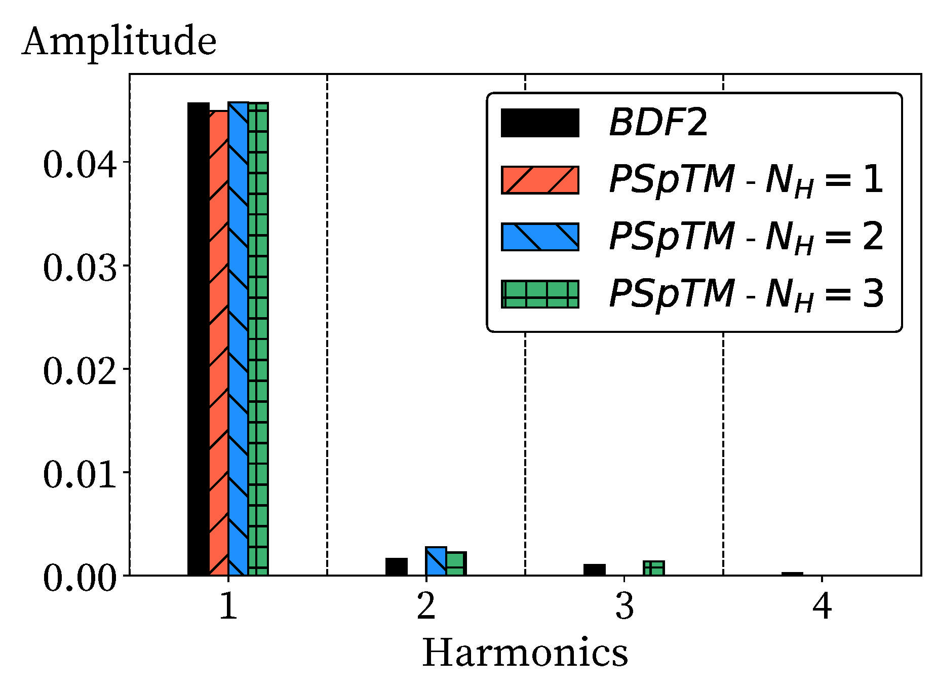
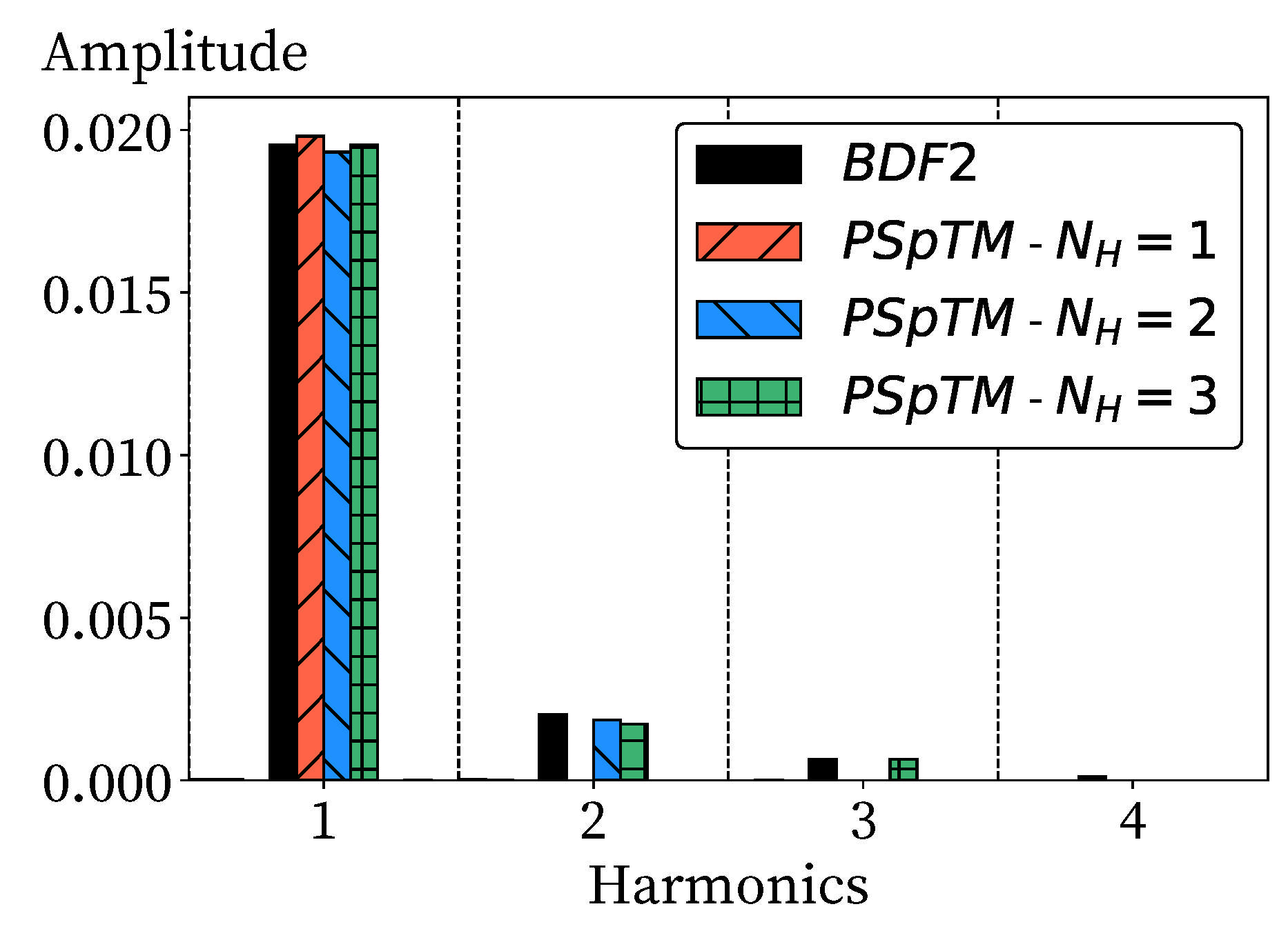
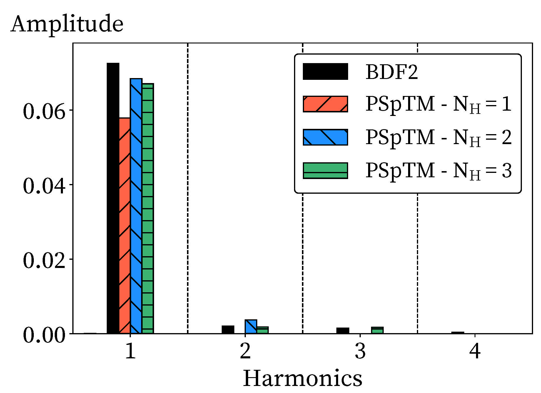
As in the previous case, to monitor the accuracy of the solution, the dimensionless mass-averaged total pressure value at the exit is used as the reference metric. Figure 9 displays the spectrum of dimensionless total pressure at the exit. In this case, the first harmonic of the solution contains most of the energy. However, the second harmonic, while smaller, is still noticeable. The PSpTM method with N H = 1 captures the amplitude of the first harmonic, but some additional energy is retained in the solution. This results in an excess in the amplitude prediction of about 1.4% compared with the BDF2 value. The accuracy of the solution increases with the number of harmonics, and the excess energy is moved towards the second harmonic. In the N H = 2 and N H = 3 cases, the relative error is reduced to −0.4% and −0.01%, respectively.
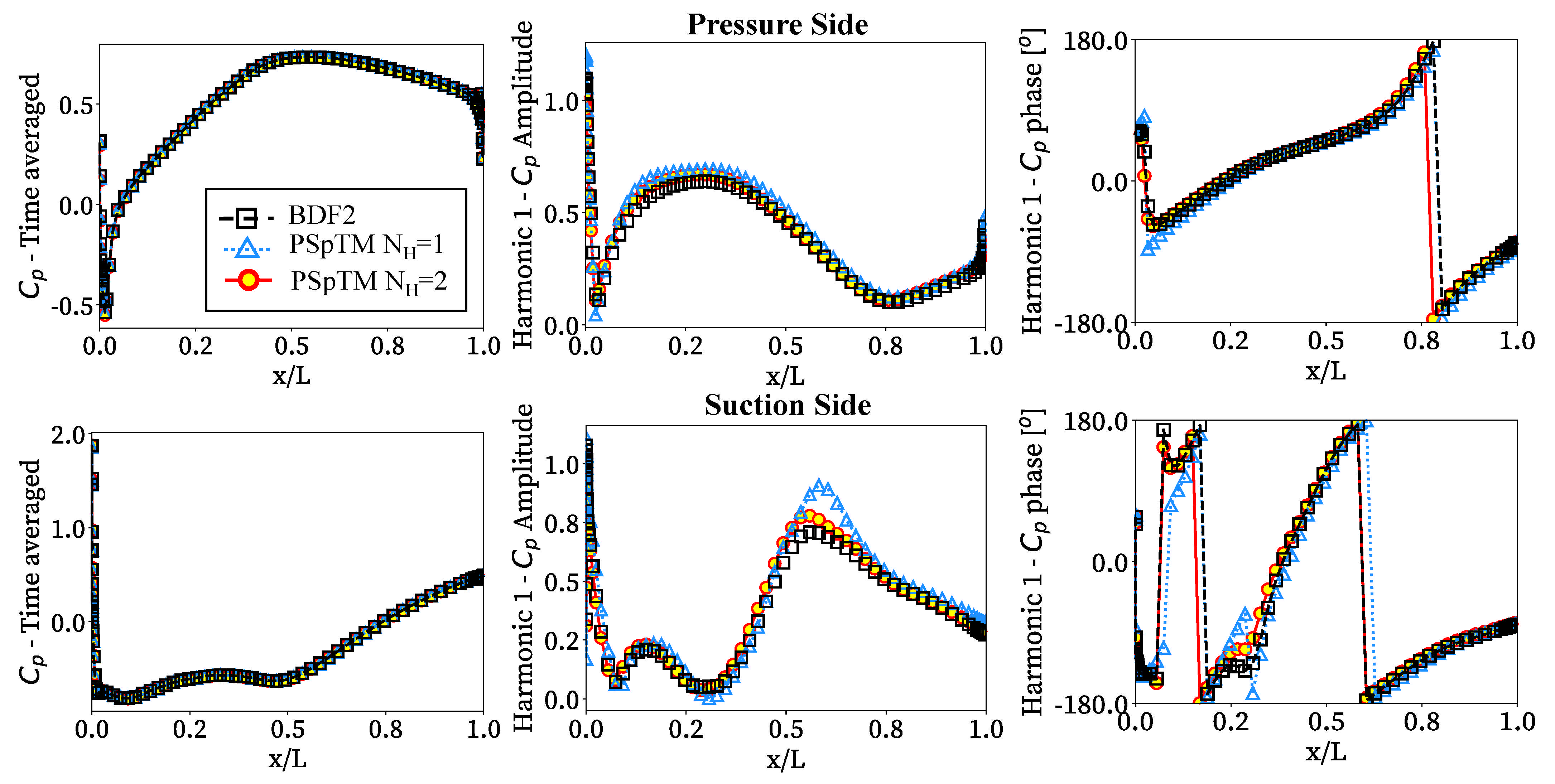
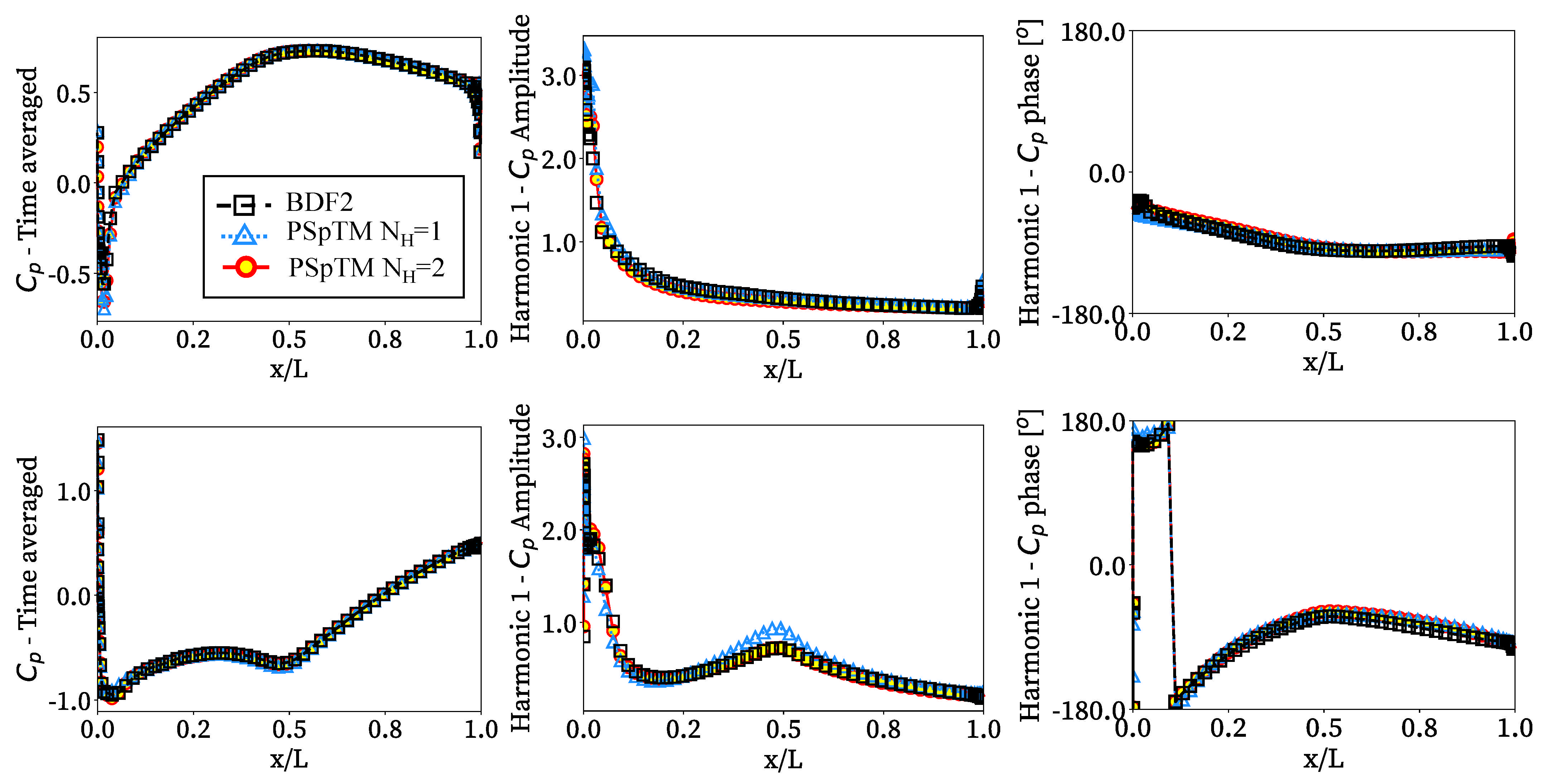
Figure 10 compares the time average and the first harmonic amplitude and phase of the pressure coefficient, C p , along the blade to assess the PSpTM’s capability to capture the local flow variations over time. In this case, while the time average C p is similar for all cases, some important differences are observed between the BDF2 and the PSpTM method with N H = 1 . The latter overestimates the amplitude of the first harmonic both in the pressure and the suction side of the blade. Some noticeable differences are also spotted in the phase of the first harmonic for the N H = 1 case. The accuracy in the prediction of the phase and amplitude increases significantly when two or more harmonics are retained. However, only some marginal gains in accuracy were achieved when more than two harmonics were included.
Figure 11 displays the periodic norm as a function of the number of periods, time speeds, and total computational cost. As in the low-frequency case, the PSpTM has a poor convergence rate in terms of the number of periods required to achieve the desired level of accuracy. As mentioned, this is attributed to an effect of the initialization of the method and the initial difficulty to reach a time-periodic solution (Figure 11a). However, for this case, the BDF2 approach also presents a slow convergence, which is much lower than the low-frequency one. This is because of the increase in frequency. As the frequency rises in comparison with the flow convection, the convergence time is dominated by the through-flow time instead of the number of periods of the fundamental frequency. This results in a higher number of iterations required to achieve the same level of periodic accuracy (Figure 11b). Hence, for a similar level of periodic convergence, the PSpTM method provides significant savings in computational cost, with a speed-up factor of approximately ten for the case with N H = 1 , five for the case with N H = 2 , and above 3 for N H = 3 .

3.3. Inlet Distortion Effects: 1st EO Potential Perturbation

To evaluate the method for other representative turbomachinery cases, a full annulus configuration of the quasi-2D fan has been chosen (Case C in Table 2). To model an intake distortion profile with EO1, a sinusoidal pressure perturbation is introduced at the inlet ( k = 1 ) (Figure 12). The fundamental frequency of the perturbation is set to the fan rotational frequency. This results in a Strouhal number of approximately S t 0.05 . The amplitude of the perturbation is set to 7.5% of the reference inlet static pressure, which is large enough to give rise to nonlinear effects. The PSpTM method is applied with an increasing number of harmonics in the solution from N H = 1 to N H = 3 .
For the BDF2 approach, 100 time steps are used per period. To obtain an equivalent level of convergence, the BDF2 method is set to have 20 and 40 Newton and Jacobi inner iterations, respectively. The maximum CFL for the implicit DTS scheme is set to 40. The case is run for 10 fundamental periods. This convergence strategy was selected from different combinations to obtain sufficient time convergence in the solution for a reasonable computational cost. As explained in previous sections, the PSpTM requires fewer pseudo-time iterations to converge each time step. Thus, the number of DTS iterations was set to 6 and 30 for the Newton and Jacobi iterations, respectively. This results in a much lower cost per time step than the BDF2 method. The maximum CFL for the inner iterations is set to 40.
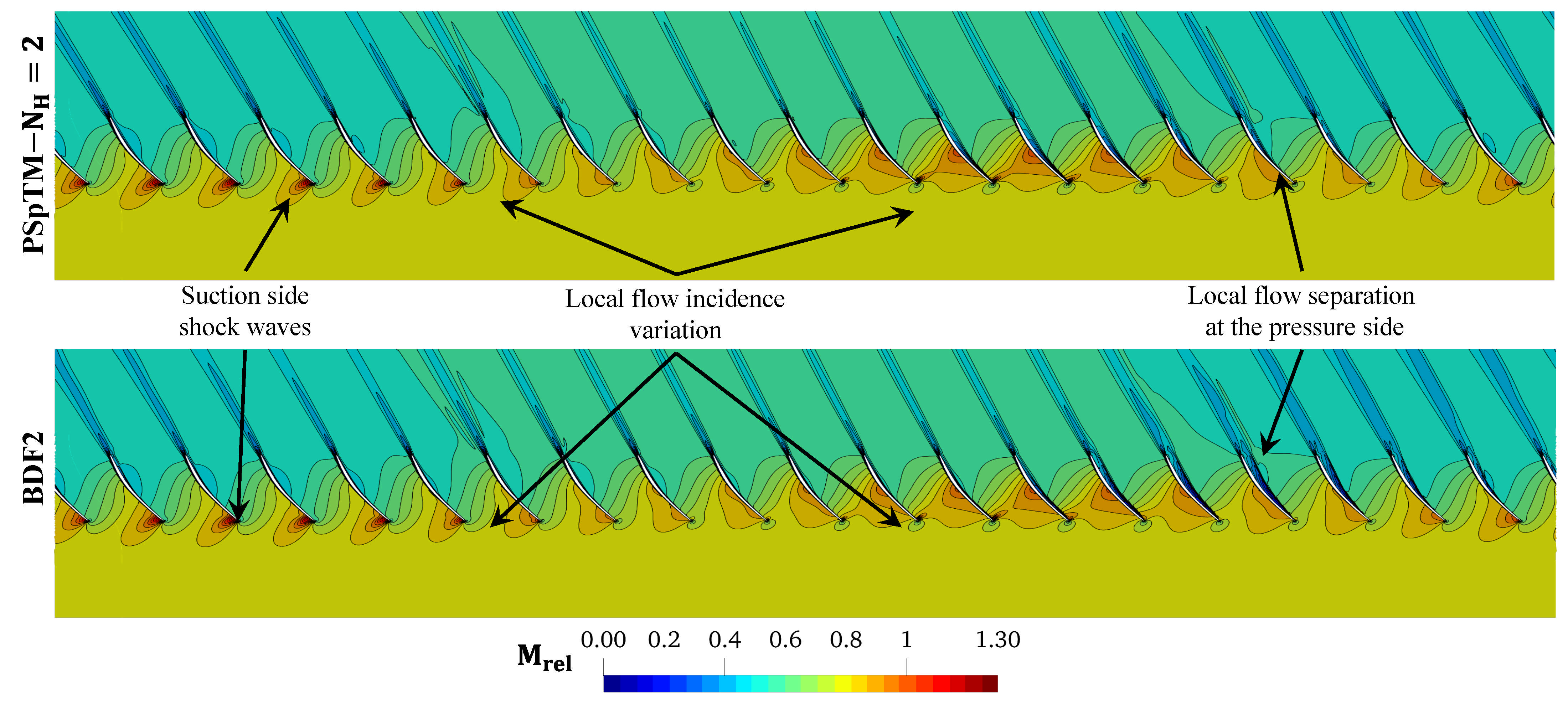
Given that each blade travels through a wide range of pressure ratios, the blade experiences a broad set of flow conditions within a rotation cycle (Figure 12). This includes notable changes in the flow incidence that displace the shock-wave from the leading-edge to the middle of the suction side. As such, notable changes in the blade forces take place during the fan rotating cycle. For this reason, to evaluate the accuracy of the model the module of the total force over one blade is tracked over time ( F ). This is normalized by the area of the blade and the reference dynamic pressure at the inlet as a force coefficient:
C F = F 0.5 ρ r e f V r e f 2 A b l a d e
The large variation of the flow conditions allows for testing the method in the presence of significant flow nonlinearities, including shock waves and synchronous flow separation (Figure 12). The robust operation of the PSpTM under these flow conditions is an apparent step-up from nonlinear methods built on top of linear methods [11,12], which have some limitations in the presence of large perturbations.
In a first evaluation, the solution that retains a single harmonic fails to capture the amplitude of the temporal variation of C f (Figure 13 and Figure 14). A notable increase in accuracy is observed when two or more harmonics are retained. A marginal gain in accuracy is appreciated with N H = 3 . However, when the amplitude of the signal is studied in depth, it appears that most of the energy is contained in the first harmonic, and the higher harmonics only contain second-order contributions. This is in line with the previous works where it has been shown that shock-wave discontinuities give rise to higher harmonics [15]. When higher harmonics (or more time steps per fundamental period) are included in the PSpTM method, the energy is distributed in higher harmonics, slightly decreasing the amplitude of the first harmonic. Overall, despite not fully matching the BDF2 results, a sufficient level of agreement with the BDF2 approach is observed with the PSpTM method with N H 2 .
From the instant flow fields obtained by both methods (Figure 12), it is understood that the PSpTM under-predicts the magnitude of the flow separation at the pressure side, compared with the BDF2 case. The flow separation could be triggered at a different offset in each temporal scheme due to the temporal accuracy of each method for a given spatial discretization. The sensitivity to the time stepper is higher for low spatial resolution. Nevertheless, without a higher-order reference, it cannot be concluded which result is the most representative of the actual flow separation. Despite this, an adequate agreement in the overall flow field is observed for both temporal schemes.
Figure 15 represents the variation of the pressure coefficient, C p , distribution over time on the pressure and suction side of the blade. The objective is to further analyze the method’s accuracy. Only the first two cases (i.e., N H = 1 and 2) are included, since no significant changes were observed between the N H = 2 and N H = 3 cases. Some discrepancies between the BDF2 and the PSpTM methods are observed for the N H = 1 case. The solution with N H = 2 improves significantly with respect to the single harmonic case, with only minor differences in the prediction of the phase and magnitude of the first harmonic of the solution.
Finally, to evaluate the periodic convergence of the solution, the periodic norm of the force coefficient is defined as
Ψ ( C f ) = ( F ( t ) F ( t T ) ) 2 ( ρ r e f V r e f 2 A b l a d e ) 2
where the force magnitude over the blade is normalized by the dynamic pressure of reference and the area of the blade. As in previous cases, a slow convergence rate is observed for the PSpTM method due to the solver initialization (Figure 16). Nevertheless, a speed-up factor of approximately 4 and 3 is achieved by the PSpTM method with N H = 2 and N H = 3 , respectively. The case with a single harmonic included does not match the same level of accuracy as the cases with higher harmonics. However, this case can achieve a speed-up factor of approximately 5.
4. Conclusions

A novel numerical method to evaluate time-periodic turbomachinery CFD problems has been applied in this paper. The method proposes an alternative approach to solve the time spectral (TS) formulation based on a pseudo-spectral formulation of the time derivative arranged in a time-marching fashion. This method was named as the Pseudo-Spectral Time-Marching (PSpTM) approach. As in other TS approaches, this method relies on knowing a priori the fundamental frequency of the time-periodic problem, which is a common situation in turbomachinery analyses. The number of harmonics in the solution must be prescribed beforehand. The increase in the number of harmonics selected for the solution will increase the accuracy of the method, but it will also require more time steps per period. This implies that there will always be a trade-off between accuracy and computational cost based on the conditions of the problem. Compared with similar methods found in the literature, the main advantage of the PSpTM method is its simplicity, since it can be easily implemented in any conventional implicit CFD solver without major architecture modifications.
In this work, the method has been tested in representative turbomachinery cases using a quasi-2D annular definition of a fan blade. Different static pressure perturbations were used for this purpose. Cases with high and low frequency were evaluated to understand the applicability of the method. In all cases, the approach reproduced the time-marching solution using just two harmonics. The pressure perturbation contained a single harmonic, but strong nonlinear effects developed during the transients. The solution with a single harmonic predicts the general trends of the solution, but nonlinear effects give rise to higher harmonics. Overall, the method can reproduce the periodic solution accurately if the right number of temporal harmonics are retained.
Notable savings in computational cost were observed when the PSpTM method was used with speed-up factors of between 2 and 10 with respect to the BDF2, depending on the case. However, the PSpTM method exhibits a poor periodic convergence rate, leaving room for further improvements in efficiency. However, even in its current form and with the current understanding, the method has a remarkable performance and is very simple to implement in any nonlinear time-marching code.

Author Contributions

Conceptualization, J.M.-G. and R.C.; methodology, J.M.-G. and R.C.; formal analysis, investigation, J.M.-G.; writing—original draft preparation, J.M.-G.; writing—review and editing, J.M.-G. and R.C.; visualization, J.M.-G. All authors have read and agreed to the published version of the manuscript.

Funding

Funded by the European Union, under Grant Agreement No 101102004. Views and opinions expressed are, however, those of the author(s) only and do not necessarily reflect those of the European Union or Clean Aviation Joint Undertaking. Neither the European Union nor Clean Aviation JU can be held responsible for them.

Institutional Review Board Statement

Not applicable.

Informed Consent Statement

Not applicable.

Data Availability Statement

The raw data supporting the conclusions of this article will be made available by the authors upon request.

Acknowledgments

The authors would like to thank Rolls-Royce plc for their support in this research. The authors also acknowledge the support of Venkata Chennuru on the technical preparation of the models.

Conflicts of Interest

The authors declare no conflicts of interest.

Abbreviations

The following abbreviations are used in this manuscript:
APerturbation amplitude
d m Weights of the spectral operator
d p Weights of the reformulated spectral operator
D t Pseudo-spectral operator
fFundamental frequency
f r o t        Fan rotation frequency ( ω r o t / ( 2 π ) )
J Jacobian matrix
kNondimensional wave number
MMach number
P Preconditioning matrix
NNumber of points per period
N H Number of harmonics in the solution
P t Total pressure
pStatic pressure
R Matrix of spatial derivatives
S t Strouhal number
tPhysical time
TFundamental period
u Vector of variables
V x Axial velocity
w Solution vector in the dual-time-step method
Δ t Physical time step
Δ τ Pseudo time step
Δ x Spatial step
θ Azimuthal coordinate
θ ˜ Azimuthal coordinate
ρ Density
Ψ Periodic norm of the solution
Ω Volume of the cell
tTotal magnitudes
xAxial component
BDF2Second order backwards implicit Euler method
CFDComputational fluid dynamics
DTSDual time step
DTS-PIPeriod informed dual time step
EOEngine orders
PSpTMPseudo-spectral time-marching method

Appendix A

This appendix contains a summarized version of the stability requirements. The current analysis is performed for a linear transport equation with fourth-order artificial viscosity ( μ 4 ) in the form:
u t + c u x = c μ 4 Δ x 3 4 u x 4
where c is the propagation velocity of the magnitude u , and Δ x is the grid spacing. This system is analogous to the Euler equations. Fourier transforming in space to perform a von Neumann’s analysis of the stability, Equation (A1) becomes
d u d t = λ u
where λ = λ R + I λ I is a complex number that describes the footprint of spatial eigenvalues.
Scaled by the discrete time step ( Δ t ), the footprint of the spatial eigenvalues for Equation (A1) is
λ I Δ t = C F L sin ( k ^ )
λ R Δ t = μ 4 C F L 2 1 cos ( k ^ ) 2
which is a function of the reduced wave number ( k ^ = k Δ x ), and the C F L = c Δ t / Δ x . For any given problem, the reduced wave number is within k ^ [ π , π ] . Thus, for a given C F L , the footprint of spatial eigenvalues λ describes a closed curve symmetric about the λ R Δ t axis and always within negative values of λ R Δ t (Figure A1). The stability of the problem is given by the amplification factor or gain function (G) for these λ . The amplification factor (G) is defined as the ratio between two consecutive time steps ( G = u n + 1 / u n ). Based on the PSpTM formulation of Equation (10), for any number of harmonics ( N H ), the amplification factor is obtained from a characteristic polynomial of order 2 N H :
p = 1 2 N H d p Δ t G 2 N H p = ( λ Δ t ) G 2 N H
For simplicity, the analysis is limited to the case with a single harmonic in the solution ( N H = 1 ). In this case, an analytic solution of the amplification factor can be obtained for the characteristic second-order polynomial:
α ( λ Δ t ) G 2 + G 1 = 0
where
α = Δ t | d 1 | = 3 sin ( π / 3 ) π
based on the weights of the spectral derivative (Equation (11)).
The resulting gain function (Figure A1) is stable ( | G | 1 ) for most of the spatial eigenvalues but for a “bubble-shaped” region around the origin. The instability “bubble” affects the longest wavelength waves (i.e., the lowest reduced wave numbers k ^ = k Δ x ). Hence, depending on the case, there is the possibility of a given frequency of the solution with low wave number to be unstable. For this reason, it is necessary to understand if these frequencies are present in the CFD solutions of interest.
Considering a solution with artificial dissipation for an arbitrary CFL number (black line in Figure A1), the key condition to guarantee the method’s stability is that the λ value for the minimum k ^ must remain outside of the instability region. That is true while an adequate choice of artificial viscosity was made, with no overlap between the unstable region and the spatial eigenvalues at high k ^ (i.e., | k ^ | π ). Artificial dissipation can be easily controlled and, for the large CFL values required for the PSpTM, it is not a critical requirement. Thus, for N H = 1 , the limit for λ ( k ^ m i n ) is obtained analytically for a pure imaginary number and | G | = 1 , through Equation (A6). This yields σ I = 3 / α = 2 π / 3 . Then, the stability condition for the imaginary spatial eigenvalue in a transport equation becomes:
| λ I Δ t | = C F L sin ( k ^ ) 2 π 3
Figure A1. Stability of the PSpTM method for Nh = 1, limits and sample footprint of the spatial eigenvalues.
Ijtpp 10 00019 g0a1
In the limit, when k ^ 0 , sin ( k ^ ) k ^ . The minimum possible wave number in a finite domain of length L is the one with wavelength equal to the domain size ( k = 2 π / L ). Given that for the PSpTM method Δ t = 1 f ( 2 N H + 1 ) , the stability condition is given by:
2 π 2 N H + 1 1 S t f 2 π 3
where S t f = f L / c is the Strouhal number of the fundamental frequency in the full domain. For N H = 1 , this yields the condition S t f 1 . This means that the method can only solve frequencies with wavelengths contained within the domain. Theoretically, this is not an issue when the problem is well conditioned because the fundamental frequency prescribed always fulfills this requirement. That is true when the waves of the solution are propagated in time and space since the start of the simulation. However, in real CFD cases, there is an initial transient in which low unstable frequencies may reside within the domain. These are frequencies lower than the fundamental prescribed frequency.
In these cases, if the domain was fully periodic and waves with a frequency lower than the prescribed value were present, the solution would be unstable, because these waves cannot abandon the domain, and they will be progressively amplified. However, turbomachinery analyses are conducted in finite-length domains, and the waves are convected downstream. Hence, unstable waves can leave the domain during the initial transient before they reach a critical value. In these cases, the stability condition is that the global amplification factor of an unstable wave is lower than a critical value at the exit of the domain. This condition is always satisfied in all the cases in this work and most internal turbomachinery flows.

References

  1. He, L. Fourier methods for turbomachinery applications. Prog. Aerosp. Sci. 2010, 46, 329–341. [Google Scholar] [CrossRef]
  2. Erdos, J.I.; Alzner, E.; McNally, W. Numerical solution of periodic transonic flow through a fan stage. AIAA J. 1977, 15, 1559–1568. [Google Scholar] [CrossRef]
  3. He, L. An Euler Solution for Unsteady Flows Around Oscillating Blades. ASME J. Turbomach. 1990, 12, 714–722. [Google Scholar] [CrossRef]
  4. He, L. Method of simulating unsteady turbomachinery flows with multiple perturbations. AIAA J. 1992, 30, 2730–2735. [Google Scholar] [CrossRef]
  5. Burgos, M.A.; Corral, R. Application of Phase-Lagged Boundary Conditions to Rotor/Stator Interaction. In Proceedings of the ASME Turbo Expo, Paper N. 2001-GT-586, New Orleans, LA, USA, 4–7 June 2001. [Google Scholar] [CrossRef]
  6. He, L. Fourier modeling of steady and unsteady nonaxisymmetrical flows. J. Propuls. Power 2006, 22, 197–201. [Google Scholar] [CrossRef]
  7. Romera, D.; Corral, R. Efficient Passage-Spectral Method For Unsteady Flows Under Stall Conditions. ASME J. Turbomach. 2020, 142, 121007. [Google Scholar] [CrossRef]
  8. Hall, K.C.; Lorence, C.B. Calculation of three-dimensional unsteady flows in turbomachinery using the linearized harmonic Euler equations. J. Turbomach. 1993, 115, 800–809. [Google Scholar] [CrossRef]
  9. Sbardella, L.; Imregun, M. Linearized unsteady viscous turbomachinery flows using hybrid grids. J. Turbomach. 2001, 123, 568–582. [Google Scholar] [CrossRef]
  10. Corral, R.; Escribano, A.; Gisbert, F.; Serrano, A.; Vasco, C. Validation of a Linear Multigrid Accelerated Unstructured Navier-Stokes Solver for the Computation of Turbine Blades on Hybrid Grids. In Proceedings of the AIAA Paper 2003-3326, AIAA, Hilton Head, SC, USA, 12-14 May 2003; American Institute of Aeronautics and Astronautics: Reston, VA, USA, 2003. [Google Scholar] [CrossRef]
  11. He, L.; Ning, W. Efficient approach for analysis of unsteady viscous flows in turbomachines. AIAA J. 1998, 36, 2005–2012. [Google Scholar] [CrossRef]
  12. Wang, F.; di Mare, L. Favre-Averaged Nonlinear Harmonic Method for Compressible Periodic Flows. AIAA J. 2019, 57, 1133–1142. [Google Scholar] [CrossRef]
  13. Hall, K.C.; Thomas, J.P.; Clark, W.S. Computation of unsteady nonlinear flows in cascades using a harmonic balance technique. AIAA J. 2002, 40, 879–886. [Google Scholar] [CrossRef]
  14. Gopinath, A.; Jameson, A. Time Spectral Method for Periodic Unsteady Computations over Two- and Three- Dimensional Bodies. In Proceedings of the 43rd AIAA Aerospace Sciences Meeting and Exhibit, Reno, NV, USA, 10–13 January 2005; American Institute of Aeronautics and Astronautics: Reston, VA, USA, 2005. [Google Scholar] [CrossRef]
  15. Crespo, J.; Corral, R.; Pueblas, J. An implicit harmonic balance method in graphics processing units for oscillating blades. J. Turbomach. 2016, 138, 31001. [Google Scholar] [CrossRef]
  16. Thomas, J.P.; Custer, C.H.; Dowell, E.H.; Hall, K.C.; Corre, C. Compact Implementation Strategy for a Harmonic Balance Method Within Implicit Flow Solvers. AIAA J. 2013, 51, 1374–1381. [Google Scholar] [CrossRef]
  17. Woodgate, M.A.; Badcock, K.J. Implicit Harmonic Balance Solver for Transonic Flow with Forced Motions. AIAA J. 2009, 47, 893–901. [Google Scholar] [CrossRef]
  18. Su, X.; Yuan, X. Implicit solution of time spectral method for periodic unsteady flows. Int. J. Numer. Methods Fluids 2010, 63, 860–876. [Google Scholar] [CrossRef]
  19. Frey, C.; Backhaus, J.; Ashcroft, G.; Geiser, G.; Winhart, B.; Stuer, H. Using Pseudo Time Marching for the Solution of Harmonic Balance Methods. ASME J. Turbomach. 2025, 147, 25. [Google Scholar] [CrossRef]
  20. Wang, F.; Weber, K.; Radford, D.; diMare, L.; Meyer, M. Convergence Acceleration of Favre-Averaged Nonlinear Harmonic Method. ASME J. Turbomach. 2025, 147, 021002. [Google Scholar] [CrossRef]
  21. Matesanz-Garcia, J.; Corral, R. Application of a novel pseudo-spectral time-marching method to turbomachinery. In Proceedings of the 16th European Turbomachinery Conference (ETC16), Paper N. ETC2025-198, Hannover, Germany, 24–28 March 2025; Available online: https://www.euroturbo.eu/publications/conference-proceedings-repository/ (accessed on 23 July 2025).
  22. Contreras, J.; Crespo, J. Quantitative Evaluation and Optimization of Feeding-Back Previous Cycles Information for Computational Fluid Dynamics Periodic Convergence. ASME J. Turbomach. 2021, 143, 101008. [Google Scholar] [CrossRef]
  23. He, X.; Fang, Z.; Rigas, G.; Vahdati, M. Spectral proper orthogonal decomposition of compressor tip leakage flow. Phys. Fluids 2021, 33, 105105. [Google Scholar] [CrossRef]
  24. He, X.; Zhao, F.; Vahdati, M. A Turbo-Oriented Data-Driven Modification to the Spalart-Allmaras Turbulence Model. J. Turbomach. 2022, 144, 121007. [Google Scholar] [CrossRef]
  25. Chennuru, V.Y.T.; Corral, R.; Rodríguez-Blanco, S.; Vahdati, M.; Zhao, F. Fan Non-Synchronous Forced Vibration Under Crosswind. J. Turbomach. 2024, 147, 051005. [Google Scholar] [CrossRef]
  26. Corral, R.; Rodríguez-Blanco, S.; Chennuru, V.Y.T.; Vahdati, M.; Zhao, F. A New Nonlinear Time-Domain Flutter Analysis Approach for Distorted Flows. J. Turbomach. 2024, 147, 071014. [Google Scholar] [CrossRef]
  27. Spalart, P.; Allmaras, S. A one-equation turbulence model for aerodynamic flows. In Proceedings of the 30th Aerospace Sciences Meeting and Exhibit, Reno, NV, USA, 6–9 January 1992; American Institute of Aeronautics and Astronautics: Reston, VA, USA, 1992. [Google Scholar] [CrossRef]
  28. Sayma, A.I.; Vahdati, M.; Sbardella, L.; Imregun, M. Modeling of Three-Dimensional Viscous Compressible Turbomachinery Flows Using Unstructured Hybrid Grids. AIAA J. 2000, 38, 945–954. [Google Scholar] [CrossRef]
  29. Meyer, R.K.; Hakansson, S.; Hage, W.; Enghardt, L. Instantaneous flow field measurements in the interstage section between a fan and the outlet guiding vanes at different axial positions. In Proceedings of the 13th European Conference on Turbomachinery Fluid Dynamics & Thermodynamics, Paper N. ETC2019-330, Lausanne, Switzerland, 8–12 April 2019. [Google Scholar] [CrossRef]
Figure 1. Example of the shifting of the future time steps to the previous period in the pseudo-spectral time-marching method. Central time step in red, time steps included in the system of equations in bold blue, other time steps in light blue.
Ijtpp 10 00019 g001
Figure 2. Scheme of the applicability of the period-informed dual-time-step technique.
Ijtpp 10 00019 g002
Figure 3. View of the mesh and domain of the quasi-2D annular cut for a single passage. Dimensions based in blade chord.
Ijtpp 10 00019 g003
Figure 4. Relative Mach number over the expanded single passage. Undisturbed flow from steady RANS evaluation and main points of the period during the inlet perturbation of 10% of the reference static pressure and St = 0.05.
Ijtpp 10 00019 g004
Figure 5. Mass flow weighted average of the total pressure ratio at the outlet of the domain for the case with low-frequency perturbation at the inlet. Comparison of the BDF2 solution (Ijtpp 10 00019 i001), the PSpTM solution (Ijtpp 10 00019 i002), and the Fourier fit of the PSpTM solution (Ijtpp 10 00019 i003).
Ijtpp 10 00019 g005
Figure 6. Spectrum of the mass flow weighted average total pressure ratio at the domain exit for the low-frequency inlet perturbation case.
Ijtpp 10 00019 g006
Figure 7. Distribution of the pressure coefficient along the airfoil for the BDF2 and the PSpTM methods for the single-passage case with low-frequency perturbation: (Left): Time average. (Middle): 1st harmonic amplitude. (Right): 1st harmonic phase.
Ijtpp 10 00019 g007
Figure 8. Unsteady norm of the static pressure in the whole computational domain for the low-frequency ( S t = 0.05 ) inlet perturbation case: (a) Convergence evaluated in periods. (b) Convergence evaluated in time steps. (c) Convergence evaluated in computational cost (CPU time).
Ijtpp 10 00019 g008
Figure 9. Fourier spectrum of the mass flow weighted average of the total pressure ratio at the domain exit for the high-frequency inlet perturbation case.
Ijtpp 10 00019 g009
Figure 10. Comparison of the pressure coefficient along the airfoil for the BDF2 and PSpTM methods for the single-passage high-frequency perturbation case. (Left): Time average. (Middle): First harmonic amplitude. (Right): First harmonic phase.
Ijtpp 10 00019 g010
Figure 11. Unsteady norm of the dimensionless static pressure across the whole computational domain for the case with high-frequency inlet perturbation ( S t = 1 ): (a) Convergence evaluated in periods. (b) Convergence evaluated in time steps. (c) Convergence evaluated in computational cost (CPU time).
Ijtpp 10 00019 g011
Figure 12. Snapshot of the relative Mach number over the full annulus EO1 inlet perturbation case. Comparison between the BDF2 and the PSpTM method with N H = 2 .
Ijtpp 10 00019 g012
Figure 13. Blade force coefficient as function of time during the last two periods with increasing number of harmonics. Comparison of the BDF2 solution (Ijtpp 10 00019 i001), the PSpTM solution (Ijtpp 10 00019 i002), and the Fourier fit of the PSpTM solution (Ijtpp 10 00019 i003).
Ijtpp 10 00019 g013
Figure 14. Spectrum of the mass flow weighted average total pressure ratio at the domain exit for the low-frequency EO1 inlet perturbation case.
Ijtpp 10 00019 g014
Figure 15. Comparison of the pressure coefficient over the blade cut for the BDF2 and the PSpTM method for the full annulus case with EO = 1: time average (left), amplitude of the first harmonic (center), and phase of the first harmonic (right).
Ijtpp 10 00019 g015
Figure 16. Unsteady norm of the force coefficient for the full annulus case with EO = 1 static pressure perturbation: (a) Convergence evaluated in periods. (b) Convergence evaluated in time steps. (c) Convergence evaluated in computational cost (CPU time).
Ijtpp 10 00019 g016
Table 1. Main geometric and operating characteristics of the ACAT rotor 1 radial section (60% blade span).
Characteristics of the ACAT Blade
Number of blades20
Hub to tip ratio0.33
Tip clearance0.2% span
Fan diameter (m)0.865
Radial cut (% span)60%
Rotational speed (rad/s)556.3
Reynolds number 1.6 × 10 6
Rel. inlet Mach number at span cut0.63
Total pressure ratio1.41
Table 2. Summary of the three cases evaluated and the CFD setup for each case, including number of physical time steps and pseudo-time iterations.
CaseStEO Δ p   ( % ) Time SchemeCFLJacobi ItsNewton ItsSteps per CycleN. Periods Run
A∼0.05010BDF250402010025
PSpTM50255 2 N H + 1 500
B∼1.0205BDF250503010025
PSpTM15305 2 N H + 1 500
C∼0.0517.5BDF240402010010
PSpTM40306 2 N H + 1 500
Disclaimer/Publisher’s Note: The statements, opinions and data contained in all publications are solely those of the individual author(s) and contributor(s) and not of MDPI and/or the editor(s). MDPI and/or the editor(s) disclaim responsibility for any injury to people or property resulting from any ideas, methods, instructions or products referred to in the content.