1. Introduction
The objective of this work is to design and control an artificial cybernetic hand using fuzzy logic. It was necessary to choose the right tools and softwares to create the hand from scratch. The content of the work consists, firstly, of creating a 3D model of the hand. Secondly, logic is also added so that the parts of the hand is rotatable (movable). Thirdly, we included in the work the ability to control the hand. Last but not least, we created a feedback control circuit and used fuzzy logic to control the movements of the fingers. The fuzzy logic will be set up so that the individual fingers can move to reach the desired points. And yet at the same time, there is no possible scenario that could occur and damage or destroy the hand. For example, if the finger was already in a final position but still trying to move by pushing on another part of the hand, it would destroy the hand.
The issue of the cybernetic hand is a complex topic and, therefore, we decided to divide the work into four basic sections:
Each of the above-mentioned sections forms a sub-objective. All the sub-objectives are important for the completion of the main objective. Moreover, the sub-objectives follow each other in the order they are listed.
Fuzzy logic represents a paradigm for an efficient and alternative methodology in designing modeling and control algorithms. It can be applied in advanced technologies, either as embedded autonomous systems or as complex distributed networked applications. By leveraging fuzzy logic, designers can achieve lower development costs, superior features, and enhanced end-product performance [
4].
Fuzzy sets have become one of the dominant factors in the practical applications of computational intelligence methods. Today, many control system developers and providers include fuzzy logic in their standard software packages as a comprehensive tool for parameter tuning and direct implementation. This capability minimizes operational costs, ensures high-quality and stable control, and enhances the functionality and user comfort of products and devices incorporating such algorithms [
5].
Control systems and algorithms based on fuzzy logic, as well as devices equipped with fuzzy logic, are easily modifiable, generalizable, and can be rapidly introduced to the market with minimal development and implementation efforts. The benefits that fuzzy logic brings to modern applications [
6] are as follows:
Fuzzy logic reduces the time required for designing and developing control algorithms.
Fuzzy logic simplifies the creation of control and decision-making algorithms.
Fuzzy logic shortens the time to market for new smart products.
Fuzzy logic replaces cumbersome and complex algorithms for controlling nonlinear processes.
Fuzzy logic enhances device performance, operational reliability, and active safety of components and systems.
Fuzzy logic simplifies implementation processes.
Fuzzy logic lowers the overall costs of control software and hardware.
The question of the use of the cybernetic hand and its control is a frequently discussed topic; it can be used in various parts of mechatronics and robotics. One possibility could be the demonstration of the finger alphabet. The hand can show different symbols. But to serve this purpose fully, the hand would also need to be enhanced with joints that would allow the fingers to move sideways because, without that, the hand can only show some of the letters of the finger alphabet. Another possibility could be to show sign language. The hand would need to add the whole arm and then duplicate it since two hands from the shoulder to the fingers are needed to show sign language. These uses described above were the fundamental vision of this work. There are certainly many more possible uses, for instance, whether to incorporate an arm to allow it to lift things. It could even act as a prosthesis for people who have lost an arm.
2. Related Works
The content of the following section presents the current state of the art. Projects that deal with the same technologies as those used in this work are highlighted. It should be noted that the topic addressed here is of interest both in Slovakia and abroad. The technologies employed are frequently applied in various important projects.
The research that has integrated this interconnection of MSC Adams and MATLAB Simulink tools in Slovakia is, for example, a project with the aim of achieving simulation-based robot arm control [
7]. Furthermore, a project similar to our work, where a five-finger robotic hand is solved and controlled using fuzzy logic, and the hand must be able to perform grasping of common objects in a reliable and repeatable way [
8].
To improve grasping capabilities in robotics, there is a study with design and test grasping capabilities and manipulation control strategies by co-simulating with a combination of SynGrasp and MATLAB [
9].
To improve the modeling and simulation of pipeline inspection robot behavior during its movement through the pipeline, there is also a study that used a combination of programs MSC Adams and MATLAB Simulink [
10].
Another similar application with a cybernetic hand is the work where researchers wanted to create a robotic pick-point evaluation for a two-fingered robotic gripper using a combination of MSC Adams and MATLAB Simulink software [
11]. From the current state of the art on these and similar issues, it can be concluded that our research on the cybernetic hand using co-simulation is not the only one in the world, but it is prospectively interesting and necessary.
But this work also has a possible continuation in a slightly different technological direction. Recognition of American Sign Language has also been the subject of research [
12]. Another possible area is the translation itself, as investigated in [
13].
Fuzzy logic has broad applications beyond robotic hands, offering substantial benefits in control, prediction, and optimization. One key area is visual tracking and control systems, where fuzzy logic enhances robustness and reduces the need for extensive adjustable parameters. For example an adaptive fuzzy logic controller is presented while used for tracking an industrial robot hand. By combining fuzzy logic with a position prediction technique, the system achieves improved behavior and robustness, ensuring the robot hand remains centered in the camera’s view with minimal manual adjustments [
14].
In robot in-hand manipulation, fuzzy logic is applied to manage the complexity of autonomous tasks such as object recognition, grasping, and positioning. There is a proposed fuzzy logic-based tactile controller that enables smooth finger motion by addressing sensor nonlinearities and uncertainties. This approach minimizes the need for exact object dimensions and precise positioning, improving the flexibility and adaptability of the robotic system [
15].
In the realm of predictive control, fuzzy logic has proven its value in predicting disruptions in complex systems. It has been demonstrated how fuzzy logic, combined with regression trees, can predict disruptions in tokamak devices, significantly improving the safety and efficiency of nuclear fusion reactors. The fuzzy system helps accommodate expert opinions and offers transparent, interpretable rules, making it ideal for understanding and forecasting disruptive events in plasma conditions [
16].
Beyond robotics and energy systems, building management systems benefit from fuzzy logic in maintaining thermal comfort, air quality, and energy efficiency. Reviews of fuzzy logic applications highlight its use in controlling heating, ventilation, and air conditioning systems and diagnosing faults, enabling more efficient regulation of indoor environments by considering multiple comfort factors simultaneously [
17].
In drying technology, fuzzy logic optimizes processes by overcoming nonlinear modeling and control challenges. Various applications of fuzzy logic in drying have been explored, categorizing them into modeling, classification, and control. These studies emphasize the benefits of fuzzy logic in improving energy efficiency and control over the drying behavior [
18].
In hydrology and water resource management, fuzzy logic is employed to handle the imprecision and vagueness inherent in hydrological data. Reviews of both pure fuzzy logic and hybrid fuzzy models in hydrology have shown significant promise in applications such as water distribution, flood forecasting, and groundwater management, improving decision-making processes [
19].
In each of these applications, fuzzy logic enhances the control and prediction capabilities of complex systems, making it an invaluable tool for improving performance, efficiency, and adaptability across diverse fields. Other relevant and recent work will be further presented during the written part of our paper for a comparison of our applications.
In recent years, the integration of advanced modeling techniques and intelligent systems has significantly enhanced the capabilities of mechatronic and robotic applications. For example, tensegrity-based systems have emerged as a promising approach for navigating uneven and unpredictable environments. By integrating multimodal strain sensors and employing deep learning models, such systems can achieve self-shape reconstruction without relying on external sensors. This innovation enables precise state recognition and adaptive behavior, expanding the potential for real-world applications in dynamic exploration [
20]. Similarly, machine learning techniques, such as Multilayer Perceptron and CatBoost models, have been utilized to improve the prediction of fluidic flow rates and reverse flow rates in flexible rectifiers. These methods demonstrate superior accuracy over traditional approaches, offering opportunities for optimization in industrial fluid dynamics, reducing waste, and promoting sustainable practices [
21]. Such advancements underscore the growing role of intelligent algorithms in enhancing system performance and adaptability across diverse fields.
To conclude this section, it is proper to state the fact that it is possible to develop such a functional hand into a real design, as proven by several teams of researchers [
22,
23,
24,
25]. However, our approach, centered on simulation with a fuzzy logic controller, offers distinct advantages over physical models. It significantly reduces development costs, eliminates the need for hardware maintenance, and is highly adaptable to virtual environments. Furthermore, a simulated hand can be leveraged for real-time virtual sign language interpretation during live events or online conferences, providing an accessible and cost-effective solution for facilitating communication in digital spaces.
3. Materials and Methods
To provide a clear overview of the study’s core functionality,
Figure 1 presents a flowchart illustrating the system’s main concept. This diagram highlights the integration of MSC Adams for simulation and MATLAB Simulink for control implementation, outlining the workflow from the initial design phase to the demonstration of sign language gestures.
In this section, the materials and methods used in the development and control of an artificial cybernetic hand utilizing fuzzy logic are outlined. The primary software tools employed include SOLIDWORKS for 3D modeling, MSC Adams for dynamic simulation, and MATLAB Simulink for system integration and control. A detailed 3D model of the hand was created in SOLIDWORKS and subsequently refined in MSC Adams to simulate realistic finger movements. The final model was integrated into MATLAB Simulink, where a fuzzy logic controller was implemented to regulate the motion of individual fingers. This approach enabled precise control of the hand’s movements, which demonstrates the effectiveness of fuzzy logic in managing complex, multi-joint systems.
3.1. Model Creation in SOLIDWORKS
As previously mentioned, the initial step to achieve the goal is to create a model of the hand. A 3D model is required to effectively demonstrate the system’s behavior, which could potentially be applied in real-world scenarios. The design of the model must be carefully considered to ensure that, for example, the individual finger segments do not collide or become obstructed during movement. For the creation of this 3D model, the SOLIDWORKS 2024 environment was selected.
3.2. Model Setup in MSC Adams
An important part of being able to control the hand model was to enrich the model with the logic necessary for use in the MATLAB environment. It was necessary to set the movement options for each part of the model, whether the model should react to gravity for example. It was also necessary to set the input and output variables. A factor for selecting a suitable tool is the ability to set the above-mentioned parameters, but also that the tool is able to save the model in a format that can be further used in MATLAB environment. MSC Adams 2023.4 was chosen as the software for this part of the work because it meets all the necessary parameters.
3.3. System Setup in MATLAB Simulink
This step consisted of integrating the model saved from the MSC Adams environment into the MATLAB Simulink environment. MATLAB version R2024a was used. A simple Simulink model was created for the motion. The heart of the simulation was a block saved from MSC Adams. Constants were introduced into the block to represent the moment for each finger to start moving when the simulation was run. After achieving movement of the modeled hand, it was concluded that control of the model using fuzzy logic is feasible.
3.4. Control of the Model Using Fuzzy Logic
Fuzzy logic is a mathematical discipline derived from fuzzy set theory. In the field of fuzzy sets, logical statements are evaluated by a degree of membership whose values range from 0 to 1. This is the fundamental difference between fuzzy and sentential logic. In sentential logic, statements are evaluated as true or false hence only two values 0 and 1. Fuzzy logic has become much more suitable for many real decision-making tasks. It is used to handle the concept of partial truth where the truth value can vary between completely true and completely false value [
26].
The general processing sequence in fuzzy expert systems proceeds in three steps:
All input values are read;
All applicable rules in the rule database are executed to compute the output function;
The outputs from the previous steps are transformed into crisp output values.
There are 2 methods in fuzzy logic for processing the previous steps. The first one is Mamdani. This method was used in this work. This method works on the basis of finding the center of gravity of the surface form after aggregating the outputs of the rules. Its disadvantage is that the calculation of the center of gravity of a surface shape may not be computationally simple. The second method is Sugeno. This method consists of finding the mean value of the adjacency function by calculating the weighted average over points where the adjacency function is non-zero. Sugeno’s method is computationally simpler [
27].
Fuzzy is solved in MATLAB using the so-called “Fuzzy Logic Toolbox”. This toolbox provides us with functions, applications, and also a block in the Simulink extension for the analysis, design, and simulation of systems based on fuzzy logic. This approach enables the insertion of a fuzzy system into another complex system model, allowing control over the individual fingers of the robotic hand model. The “Fuzzy Logic Designer” is a tool in MATLAB that allows us to design and test fuzzy systems. The designer allows us to set input and output variables, set fuzzy conditions and rules, set the type of defuzzification, and set many other details [
28].
4. Case Study
The following section presents the process undertaken in developing the mechatronic arm. It begins with an overview of the project, followed by a description of the work in SOLIDWORKS, where a 3D model of the mechatronic hand was created. Next, the integration of the hand’s properties in the MSC Adams environment is discussed, along with the subsequent import of the model into the MATLAB Simulink environment. Finally, the section concludes with an analysis of the fuzzy control applied to the described mechatronic hand.
One of the first points was that the hand does not have to meet any force properties, as it will not be used for handling objects. The purpose was to make a hand that could, for example, show a few learned gestures. This mechatronic hand should show the Slovak Sign Language alphabet.
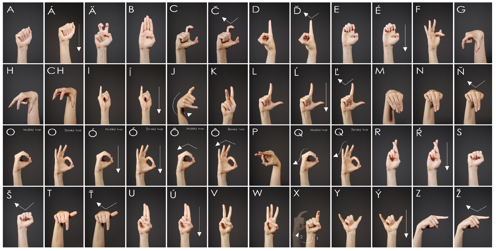
Another parameter considered was how the individual fingers of the hand would be controlled. The fingers are designed to be controlled in such a way that, if the hand were to be manufactured, each finger would be actuated by a single motor. This means the segments of each finger are mechanically linked, so when the first segment of a finger is actuated, the subsequent segments of that finger are also moved in the same manner. As a result, the hand cannot display the entire finger alphabet. To fully represent the finger alphabet, each segment of every finger would need to be controlled independently. Additionally, each finger would require the ability to move perpendicularly to the palm, in addition to moving toward and away from the palm. For better clarity,
Figure 2 is provided, illustrating the finger alphabet. In conclusion, this mechatronic hand is not capable of representing all of the signs shown in the figure.
Another important consideration was that the mechatronic hand must be modeled in such a way that the individual fingers do not collide with each other. Each finger should have its own distinct path, ensuring that no other fingers interfere with its movement. Such collisions could damage the model, or if the design were to be built in the real world, it could also damage the motors responsible for controlling the fingers. Therefore, it was essential to develop a hand model where collisions between fingers are impossible, assuming that all finger segments move uniformly.
Another factor was the variable presented by the model in the MSC Adams environment, which indicates the state of the controlled finger. Since each finger is controlled by only one variable and all the segments exhibit the same motion, the angle between the palm and the first segment of each finger was selected as the output parameter from the MSC Adams environment. This angle allows for the determination of whether the finger is extended or bent.
Finally, the settings for the fuzzy controller, which will control the individual fingers of the model, were established. To make the results more realistic, it was decided that the fuzzy controller would control each finger using torque. The torque is the output of the fuzzy system. It was also determined that the fuzzy controller would respond to two variables. The first is the deviation of the current finger angle of inclination from the desired finger angle of inclination. The second variable is the derivative of the first variable, the angle deviation, as the derivative can indicate the direction of change in the current angle and the intensity of that change. Using these two variables as inputs to the fuzzy system, the movement of the fingers was controlled.
4.1. SOLIDWORKS Section
The 3D model of the hand was built in SOLIDWORKS software. An important consideration was the aforementioned fact that no collision between the individual fingers could occur. The model was created sequentially, starting with the base part, the palm. The individual segments for the first finger, the index finger, were then created. The same segments were later used for the middle and ring fingers. The next step involved creating the smallest finger, the little finger, and finally, the thumb was built to complete the task.
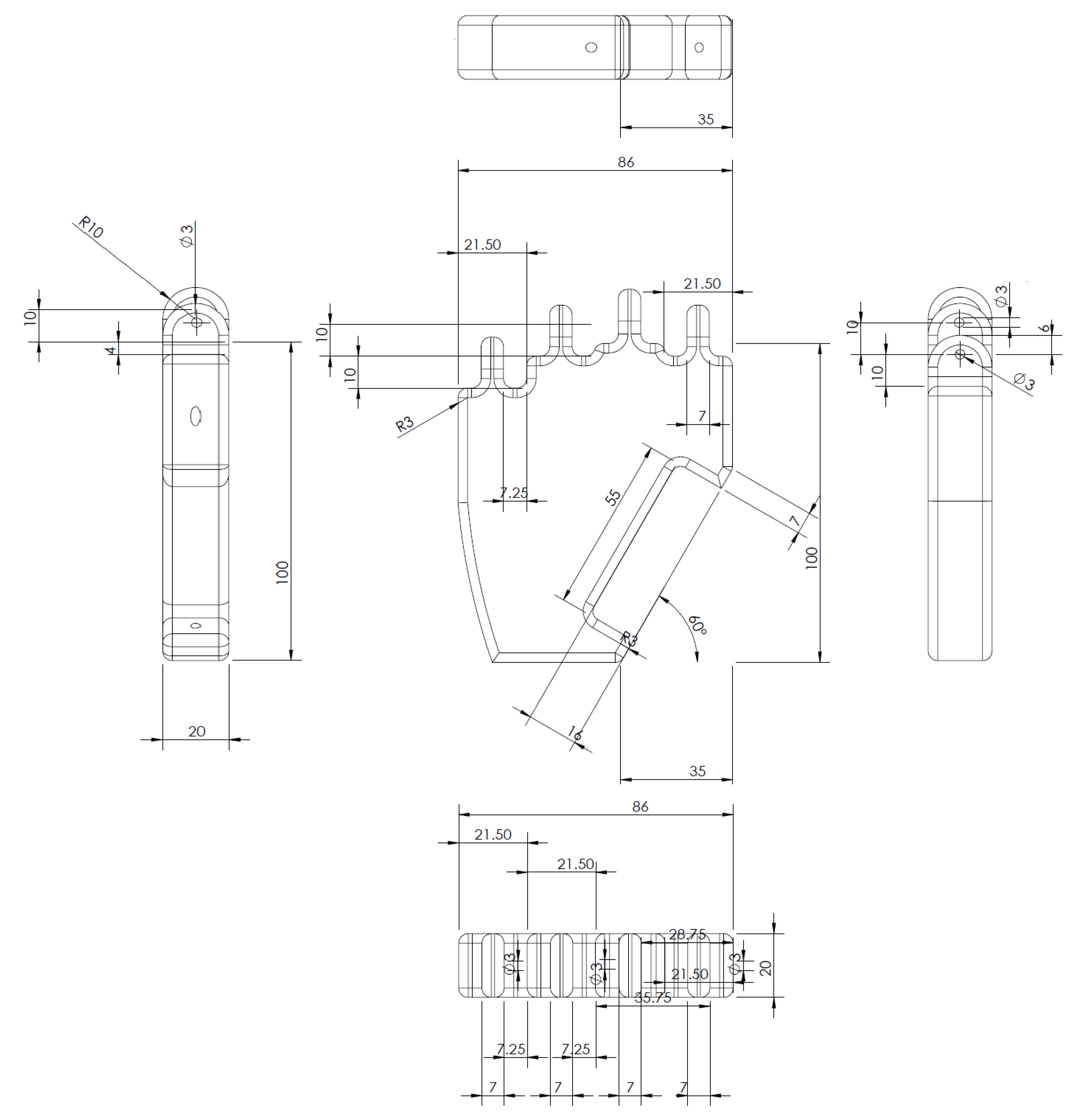
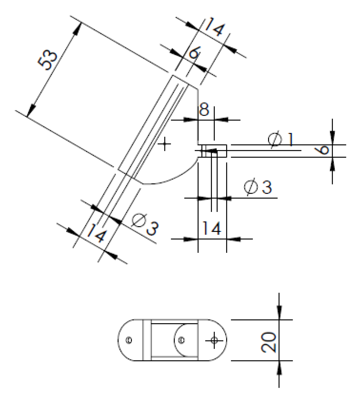
The palm is the base of the mechatronic hand model, as it connects all the fingers. This is why the palm was chosen to be modeled as the first part. The palm has a height of 117 mm and a width of 86 mm. Each corner of the palm is rounded with a radius of 3 mm, and it is 20 mm thick. The chosen dimensions were selected to correspond to those of a real palm. All dimensions given in all the figures will always be in millimeters. The palm has four connecting parts for the four fingers at the top. Each connecting part has a circular hole in it, this hole is used to connect the palm to the first links of the fingers at a later phase. The upper half of each connecting part is round, thus forming a semicircle. In the lower right-hand corner is a section cut-out into which the first link of the thumb is inserted. There is also a hole for the connection of the thumb to the palm of the hand. For a complete idea of the 3D model of the palm,
Figure 3 is presented. The 3D models shown in this work are mostly captured in a different CAD program, Inventor 2024 by Autodesk [
30]. The 2D views of the palm model and all the corresponding dimensions are shown in
Figure 4.
The index, middle, and ring fingers will be introduced at the same time because the model of each of these fingers is exactly the same. The only difference is the height at which they start from the bottom of the palm. One of the fingers, the middle finger, is 4 mm above the other two fingers. This has already been apparent in
Figure 3 and
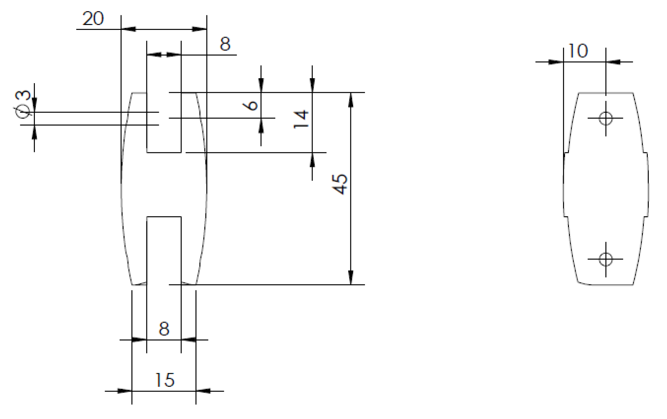
Figure 4. Each of these fingers consists of four parts. The first segment attaches directly to the palm. It is 45 mm high and has cut-outs at the top and bottom, by means of which it attaches to the palm, and at the same time, another segment attaches to it. The first segment can be seen in
Figure 5 with the dimensions. This segment is referred to as the proximal phalanx.
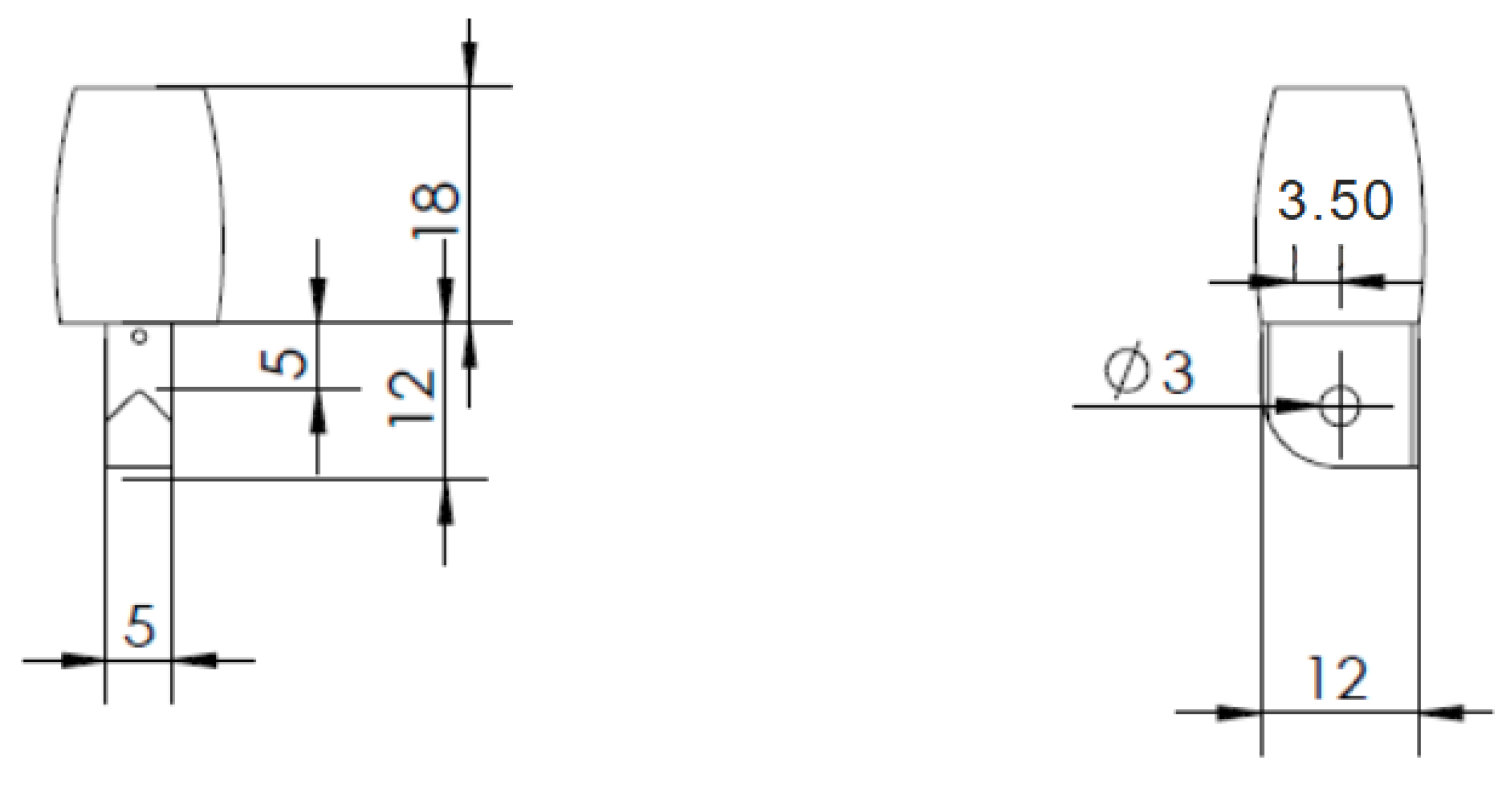
The second segment of the fingers is 41 mm high. On the lower part there is a pin, by means of which it is connected to the first segment proximal phalanx. In the upper part, it has a hole cut in the same way as the previous one for the pin of the next segment. The second segment can also be seen in
Figure 6. This segment is referred to as the middle phalanx.
The second to last piece of the model of these three fingers has again a smaller height, namely 29 mm. At the bottom we find again the pin, which connects it to the previous segment middle phalanx. On the upper side, it is circular in shape because of the last part of the finger model. The third segment can be seen in
Figure 7. This segment is referred to as the distal phalanx.
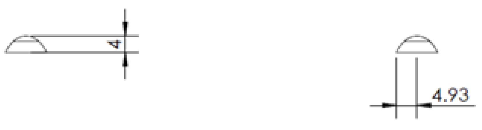
The fourth and last piece that forms these three fingers will be called a nail for the sake of simplicity. It is only 4 mm high. The nail comes on top of a segment distal phalanx. It can be seen in
Figure 8, also with the dimensions.
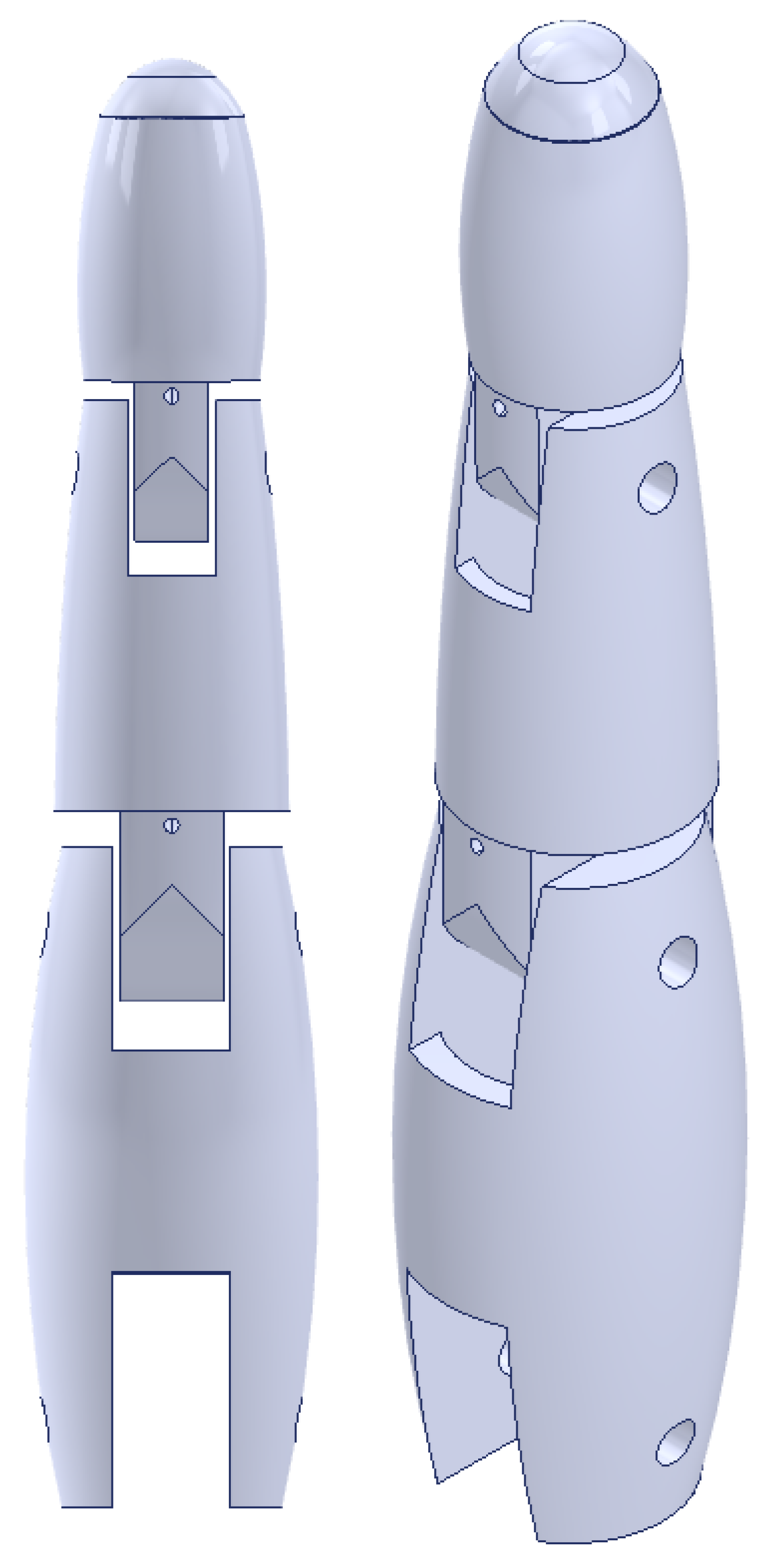
Finally, in
Figure 9, the entire finger is shown with all the described segments in both frontal and isometric views. As previously mentioned, the index, middle, and ring fingers all have the same structure.
Another part of the model is the little finger. This finger is very similar, almost identical to the previous three fingers. The only difference is that the first two segments of the proximal and middle phalanx are slightly smaller. This is because the little finger on the human hand is also smaller than the other three fingers. The creation of the individual segments will not be described again, as they have the same shapes as those of the previous fingers. For completeness, views of the smaller segments of the little finger with their dimensions are given in
Figure 10.
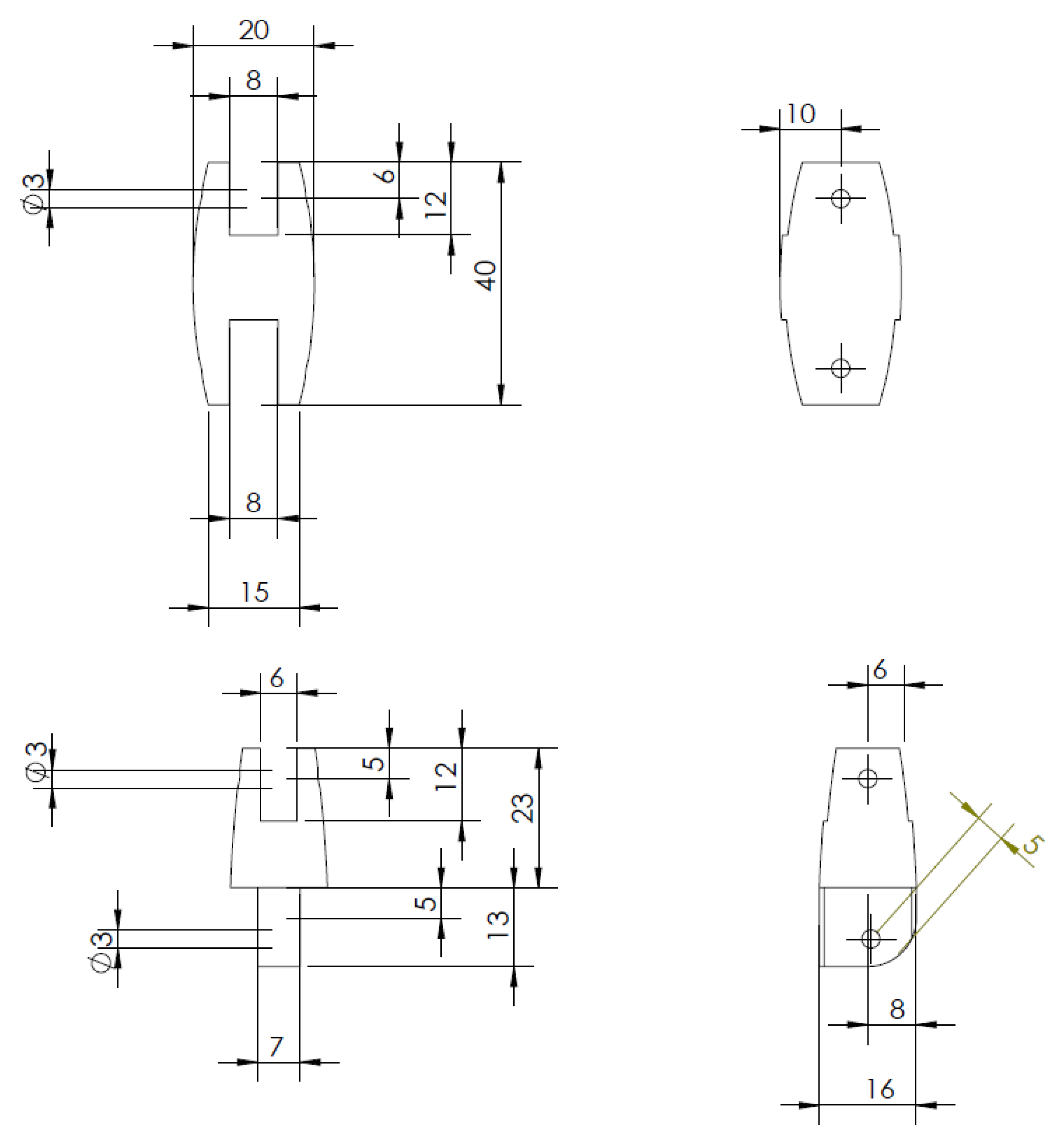
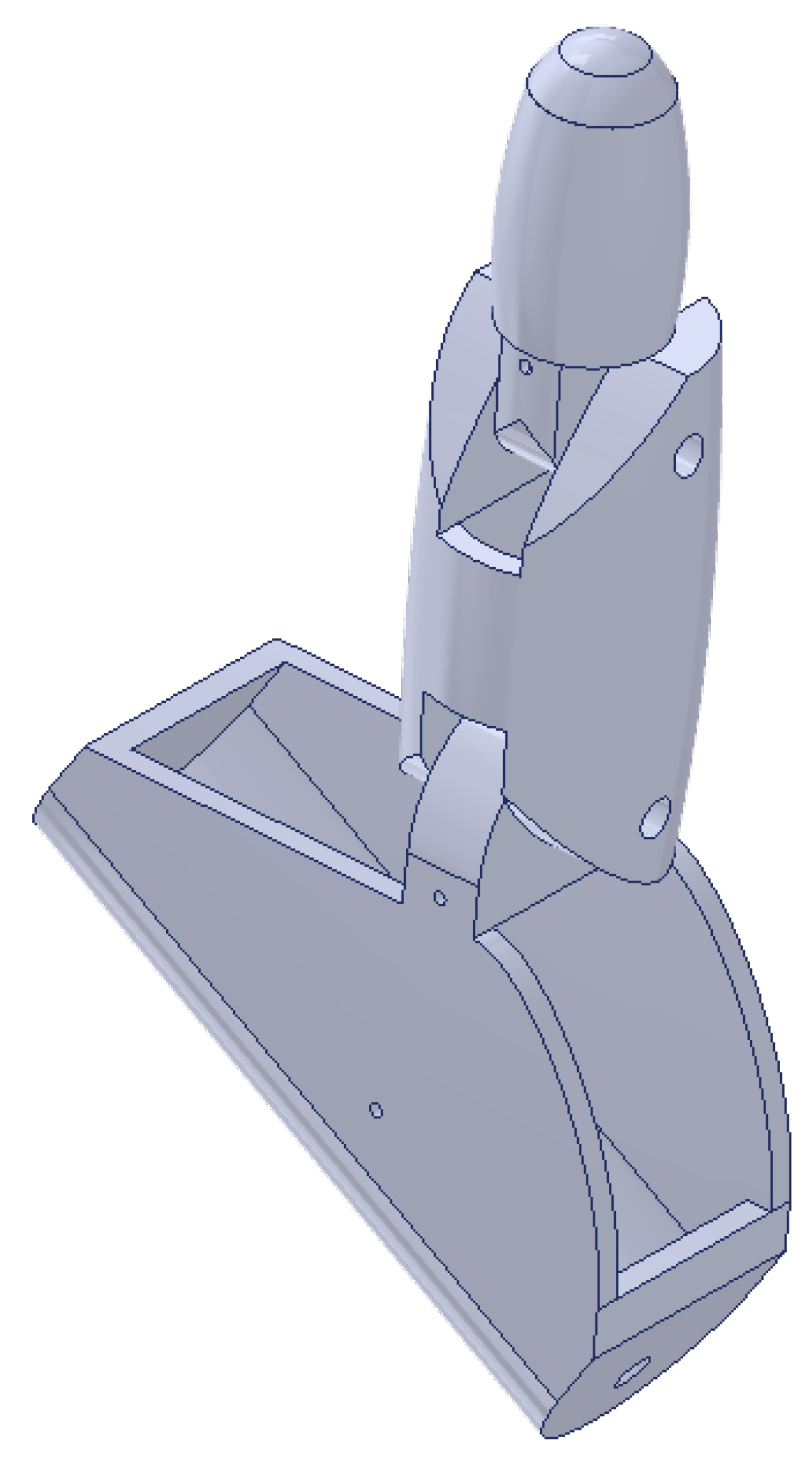
The last part of the hand, and also the last different finger, is the thumb. The thumb also consists of four segments. The first segment is completely different from the previous four fingers. It is different because it has to fit into a cut-out that is located on the lower right of the palm. We can already see the cut-out in
Figure 4. This first segment will be called thenar eminence, and its 2D views, along with the dimensions, are shown in
Figure 11. The 3D model of thenar eminence can be seen in
Figure 12.
The other three segments are the same, as we have already seen with the previous fingers. The second segment of the thumb is the same as the one used in the little finger for the proximal phalanx. The last two segments are identical to all the other fingers. In
Figure 13, we see all the thumb segments joined together, i.e., the thumb as a whole.
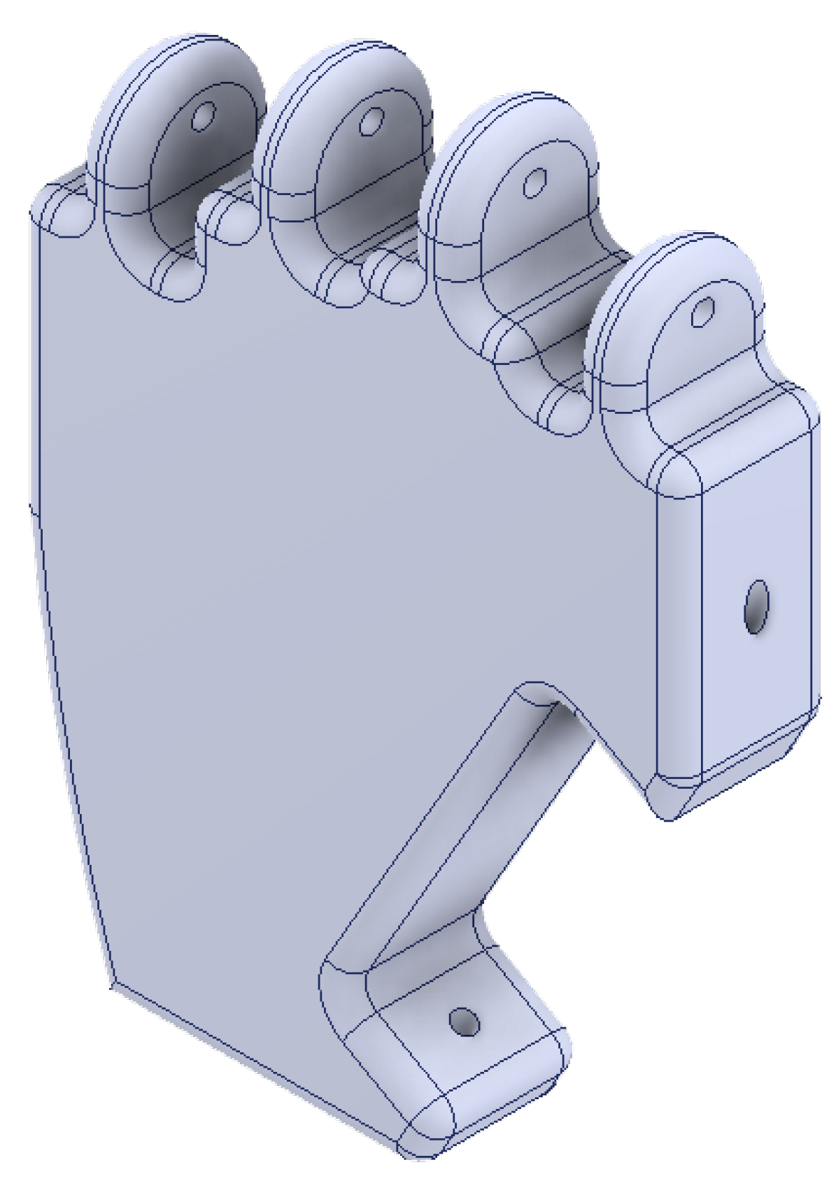
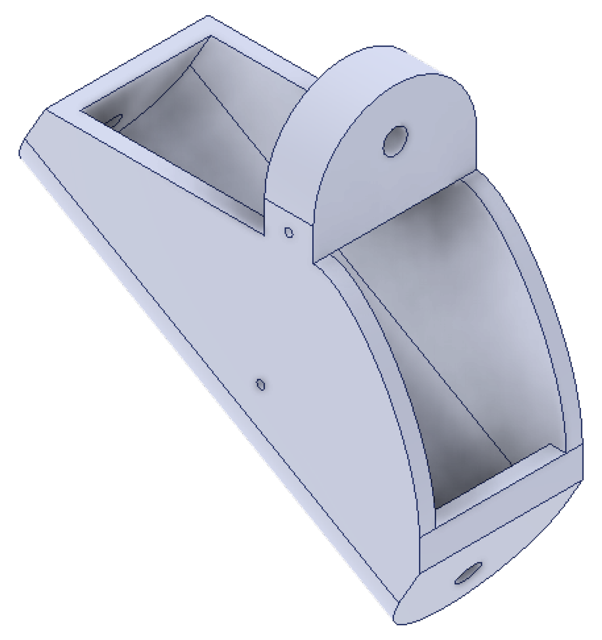
Finally, an assembly of the individual parts of the hand was made to create a model of the entire hand. The total height of the hand is 202.77 mm, width 146.10 mm, and thickness 20 mm. How the complete hand looks like can be seen in
Figure 14.
4.2. MSC Adams Section
Analysis and simulation of a robotic manipulator in MSC Adams to show the working region has been successfully demonstrated, highlighting the effectiveness of this approach for understanding and optimizing robotic systems [
31].
This cybernetic hand model has been simplified in geometry by not including irrelevant components, such as motors or gears, for simulations. In the MSC Adams environment, it was simplified by neglecting the effects of gravity and friction in the interest of creating an adequate, but not unnecessarily complicated, model.
It was considered that if the hand were to be built in the future, its production would be carried out using a 3D printer, following approaches that utilize low-cost, open-source, 3D-printable designs for dexterous robotic hands intended for applications such as sign language reproduction [
32]. For this reason, the material chosen and assigned to the hand is the one typically used in 3D printers. This material is abbreviated as ABS, with the full name Acrylonitrile Butadiene Styrene, and a density of 1050 kg m
−3 [
33].
First, the hand was anchored in the environment by restricting all degrees of freedom of the palm through a fixed joint between it and the ground. Next, it was necessary to ensure that the fingers rotated at each joint while preventing the segments from moving horizontally or vertically. The fingers were designed to rotate at the points where the individual parts of the hand have circular holes, which are also appropriately connected in the 3D assembly. This was achieved by assigning a revolute joint constraint at these locations. Additionally, a fixed joint was used to link the individual nails to the corresponding fingers, ensuring that they would move simultaneously with the fingers during simulation, i.e., with the distal phalanx. Each finger segment was constrained to alter its angle in proportion to the change in the angle of the first finger segment of the proximal phalanx relative to the palm.
Finally, in order to make the hand model controllable in the Simulink part, it was necessary to determine the variable by which the fingers of the model will be independently controlled, and in this case, it is the torque. Controllable torques via variables were, therefore, also assigned to the respective parts of each finger. But of course, for a fully functional control loop, it is also necessary to determine the parameters that are used for feedback. The variables that the fuzzy controller will need are the angle of each finger (between the palm and the first segment of the finger) and its derivative. Therefore, as a last point in MSC Adams, measurement devices for these variables have been created. Thus, the input signals to the hand model are the five variables that control the torque. The output signals are also made up of five variables that store the values of the angles for the individual fingers.
4.3. MATLAB Simulink Section
To introduce the logic underpinning the control system, a flowchart has been added to provide an overview of the desired functionality,
Figure 15. This diagram captures the high-level logic that governs the system.
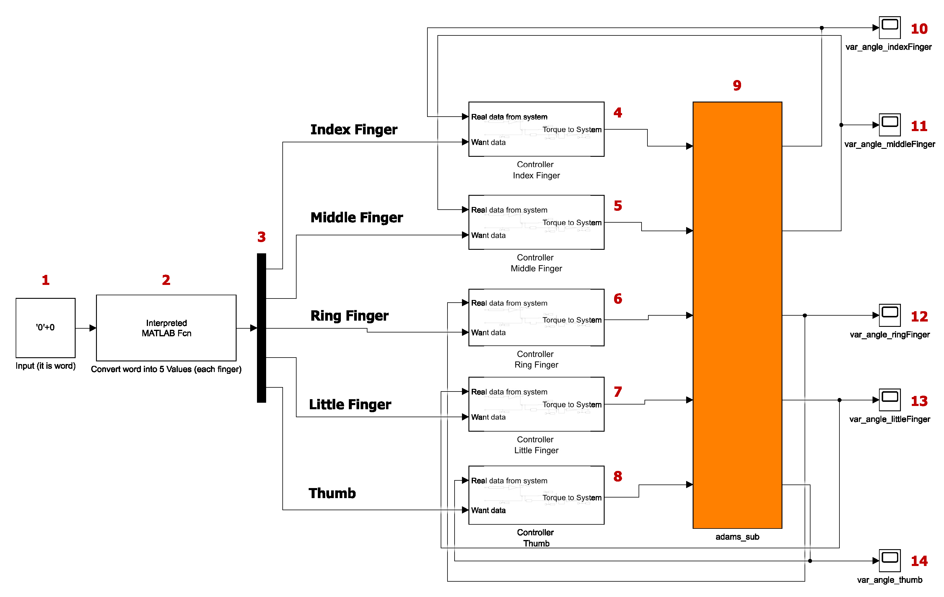
The base scheme of our control system model with the labeling of the individual blocks can be seen in
Figure 16. The hand will be capable of demonstrating several signs from the Slovak Sign Language alphabet. To enable the hand to gesture different letters, they must first be entered into block 1. A selection of known letters, including “s, b, c, d, i, l, u, y”, along with the character 0 for the default position, is inputted. When a zero is entered in the block instead of a letter, the hand will return to the initial position. The initial position of the hand is with all five fingers extended.
Experimentally, it was found that the maximum angle by which the position of the finger can be changed relative to its base position (extended finger) is 82 degrees. When the finger moves 82 degrees, it does not yet touch the palm, leaving a small but sufficient reserve. However, to simplify operations and calculations, it was determined that the number zero would represent the extended finger and the number one the bent finger. This means that 0 represents the starting position, indicating no deviation from the starting position of the finger, and 1 represents the maximum deviation from the starting position, which is 82 degrees. This does not imply that the system will only be able to show the extended or bent finger. Any real number in the range of 0 to 1 can be used. For example, the number 0.5 will rotate the finger by 41 degrees. The block labeled 2 in
Figure 16 works based on this setting. It is a block that represents a MATLAB function, and what it does is take the input from block 1 and, based on the known values, transform that input into an array of five numbers. These numbers represent values from 0 to 1 for individual fingers in order.
Then the signal enters the demux block; in
Figure 16, it is labeled with the number 3. The function of this block is that it takes a signal that carries multiple values and splits it into multiple separate signals. In our case, this means that it takes the signal from block 2 and splits it into five separate signals, where each signal represents the wish value for a single finger. It is called a wish value because the character the user wants to demonstrate with the hand is inserted into block 1, while block 2 supplies the representation of the values for the individual fingers. This representation corresponds to the character the user wishes to display, and therefore, these values are referred to as the wish values.
The next part, as we can see again in
Figure 16, is several blocks under each other. The blocks labeled numbers 4 to 8 represent the subsystems that control the individual fingers. These subsystems work in parallel in our scheme because all the fingers of the hand are controlled at the same time. What each subsystem contains will be described below. However, the subsystem takes as inputs a desired value from 0 to 1 and an angle value from the model created in MSC Adams, which represents feedback for us. As the output provides a finite torque, one subsystem handles the control of one finger.
There are also five blocks in
Figure 16 labeled 10 to 14. These are just scopes for plotting the progression of variables, specifically the values of the angles that each finger makes with the palm of the hand. Also seen in the figure is the block labeled 9, this block represents the elaborated hand model from MSC Adams. The content of the block generated by the MSC Adams software can be seen in
Figure 17. In this figure, there are five entities representing input variables on the left and five entities representing output variables on the right.
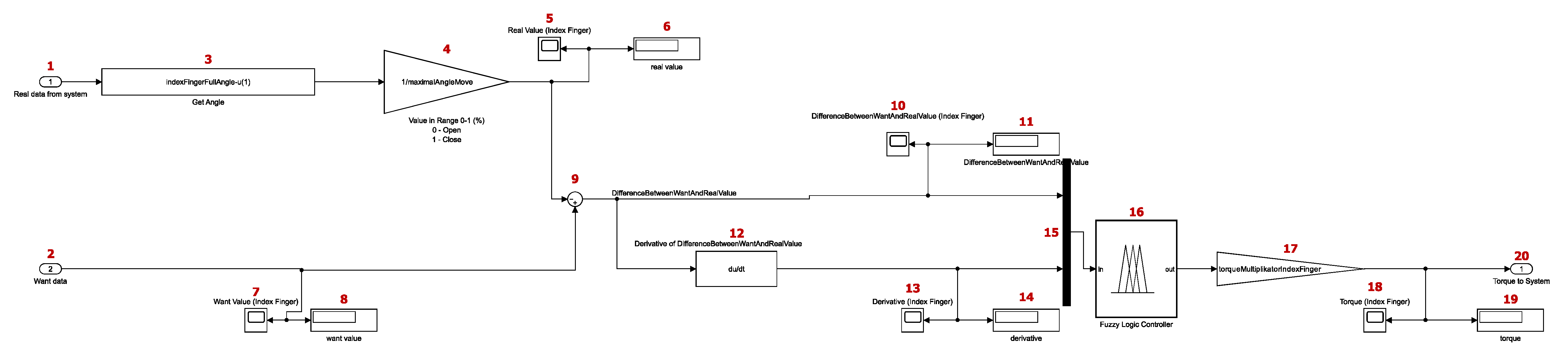
4.3.1. Control Subsystem
As previously stated, the blocks labeled 4 to 8 in
Figure 16 represent the subsystems for controlling the individual fingers and are, in principle, identical. A pictorial schematic of the entire subsystem can be seen in
Figure 18.
The subsystems work with 11 constants. The first of these is a number that defines the maximum possible finger movement and, for reasons explained earlier, stores the value 82. The other 10 constants are defined individually for the fingers. This means that there are two constants per finger. The first is the angle that the finger makes with respect to the palm in the base position and stores values around the number 176. The second of these constants is the number by which the output of the fuzzy control is multiplied. The fuzzy control provides a value for the torque, which takes on a value between 0 and 1 (in both directions). To adjust this, a constant with a value of 2.1 has been added, which multiplies the signal from the fuzzy control.
To explain the scheme of
Figure 18, the block labeled 1 represents the input variable. This variable comes from the scheme of
Figure 16. In
Figure 16, we can see that the first input to the subsystem is the feedback from the block generated by the MSC Adams environment. The first input parameter represents the current angle that the finger makes with the palm. Also block number 2 is an input parameter. This second input parameter represents the wish value for the given finger. As mentioned earlier, the wish value is in the range of 0 to 1. The block labeled number 3 is the block that subtracts input parameter 1, the angle from the feedback from the finger angle in the base shape. This gives a value from 0 to 82, which means that 0 represents an extended finger and 82 represents a fully bent finger. Block 4 is the gain multiplying (dividing) the input signal. After this division of the signal, a value between 0 and 1 is obtained, where 0 represents an extended finger, and 1 represents a fully bent finger. Blocks 3 and 4 were used to adjust the individual input parameters of the subsystem to the same range since the wish value (block 2) is in the range from 0 to 1. Blocks labeled 5 to 8 are informative blocks used to track the parameter values, including scope and display-type blocks.
Block 9 is a sum block, and in this work, it is used to subtract the feedback value from the wish value. Specifically, input 1, modified by blocks 3 and 4, is subtracted from input 2. The output signal represents the difference between the wish value and the value represented by the current finger position. This signal ranges from −1 to 1. This means that, for example, if the desired finger position is extended (value 0) and its current position is bent (value 1), the output signal from the sum block will be −1. Negative values indicate that a movement is required toward the base position from the palm, while positive values represent movement in the opposite direction. A value of 0 means that the finger is in the desired position. Next, the signal is branched, with one branch entering derivative block 12. Using the derivative, we can determine whether the finger is currently moving and, if so, its intensity and direction. Blocks 10, 11, 13, and 14 are tools for observing values.
Subsequently, in mux block 15, the signal is recombined to enter the fuzzy controller, that is, block 16. This controller takes two inputs: firstly, the difference between the desired value and the actual value, and secondly, the derivative of the first input. The output of the controller is a torque ranging from −1 to 1, depending on whether the finger should move toward the palm or away from the palm. The principle of the fuzzy controller will be described in more detail in the next subsection.
The signal coming out of the fuzzy controller then goes to gain block 17. This multiplying tool uses a slightly different constant for each finger because they are different in size, weight, etc. However, the fuzzy controller has been used the same for all 5 fingers, meaning that the output from the fuzzy controller is multiplied by the coefficient specific to each finger. By using this coefficient, the control was achieved with minimal over-regulation. The signal coming out of block 17 only goes to the informative blocks (18 and 19), and block 20 represents the output parameter for control. This signal goes further in the basic scheme shown in
Figure 16 to the block representing the hand model.
4.3.2. Fuzzy Logic for Control
The use of fuzzy logic is widely practiced in mechatronic applications, as shown in studies focused on modeling and control of mechatronic systems using fuzzy logic [
34]. This logic can also be advantageously applied in direct control applications of robotic arms, including hybrid fuzzy-sliding grasp control for underactuated robotic hands and improvements in robotic hand control via adaptive fuzzy-PI controllers using classification of EMG signals [
35,
36].
Fuzzy control is a mechanism in our process that both takes care of whether a positive or negative moment is sent to a given finger, but also how intense the change should be. This controller is used in each of the five subsystems described. However, this does not imply that each finger is controlled in exactly the same way, as the fingers differ in dimensions and weight. These parameters are important when controlling the torque, which is why a constant has been introduced to multiply the resulting torque. A constant has been assigned to each finger, and through this, better control results were achieved. As mentioned earlier, the controller uses two inputs and one output. To recap, the first input is the deviation between the wish value and the actual value of the finger, while the second input is the derivative of the deviation. The output is the torque.
The fuzzy controller was created using a tool in the MATLAB environment, along with the entire simulation scheme. The Mamdani FIS model was selected for the fuzzy logic controller due to its intuitive design and suitability for applications, which require smooth transitions and interpretable rules. Mamdani’s approach generates output values through a defuzzification process, making it particularly effective for controlling continuous systems like the motion of a robotic hand. Additionally, the defuzzification method was set to “centroid”. The most challenging aspect was configuring the various input and output parameters, as well as defining the rules, which will be described in more detail.
In the design of the fuzzy logic controller,
Figure 19, Gaussian membership functions were chosen due to their smooth and continuous nature, which ensures gradual transitions between fuzzy sets. This characteristic minimizes abrupt changes in the output, resulting in smoother and more natural finger movements, which are crucial for the accurate representation of sign language gestures.
Additionally, Gaussian functions are computationally efficient and well-suited for modeling systems where precision and fluidity are essential. When defining the fuzzy rules, all combinations of the input membership functions were considered. This approach ensures that the controller can handle all possible scenarios of input variable interactions, providing robust and consistent control across the entire operating range. By covering every combination, the fuzzy controller can respond effectively to various conditions, ensuring precise and adaptive motion control.
This model was chosen because it allows for straightforward rule formulation using linguistic variables, which is beneficial when designing a system with human-readable logic. Additionally, the centroid defuzzification method used in the Mamdani model ensures precise and smooth control outputs, which are critical for achieving natural and accurate finger movements in the simulation.
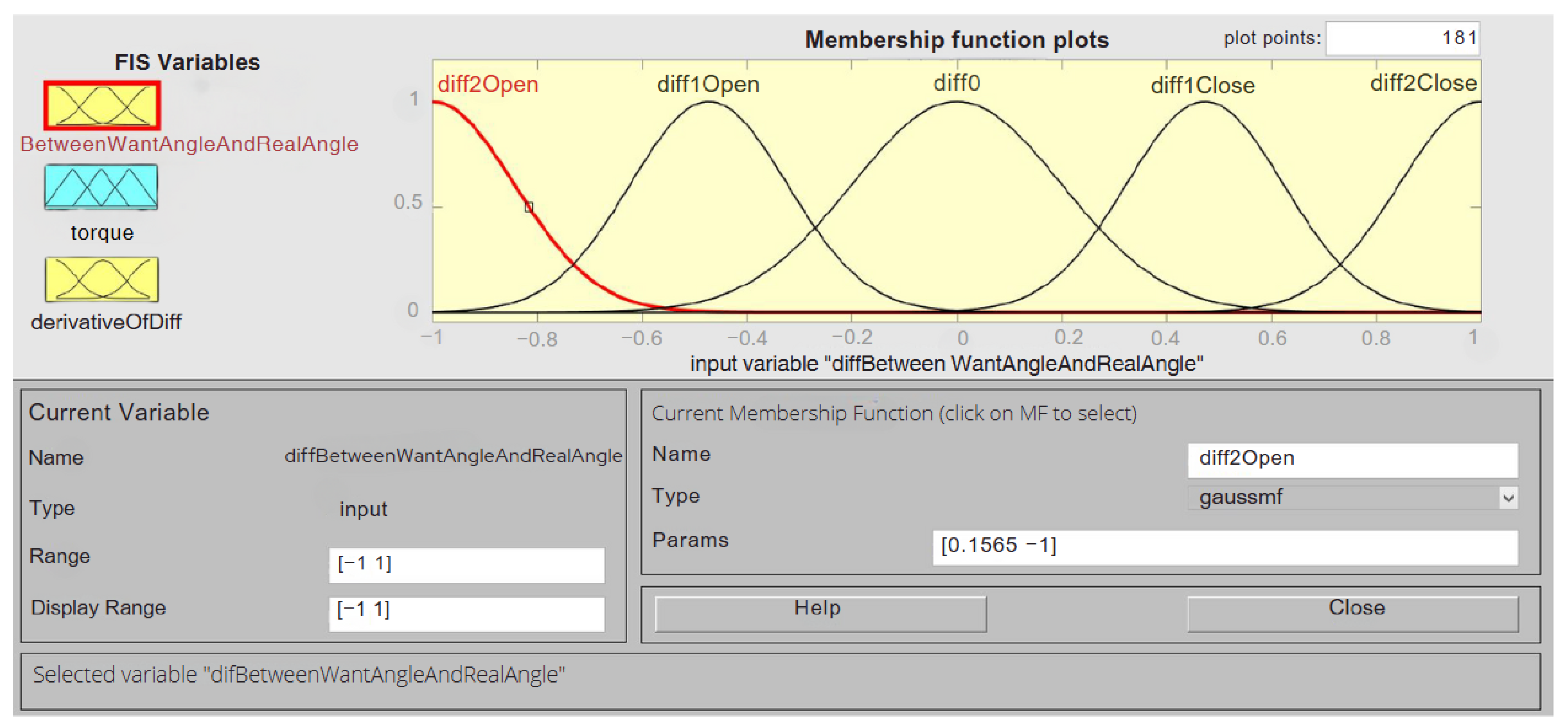
The setting of the first input variable can be seen in
Figure 20. Membership functions of the “gaussmf” type, which have the shape of a Gaussian curve, were used. A total of five membership functions were employed. The cardinality of 5 was selected based on the authors’ extensive experience in designing fuzzy controllers, as demonstrated in previous studies [
37,
38,
39,
40,
41,
42]. This choice represents a balance between computational efficiency and control precision, ensuring sufficient granularity to achieve smooth and accurate finger movements without introducing unnecessary complexity.
Triangular fuzzy sets were used for the output variable because they provide crisp transitions between output states, which simplifies computation while maintaining effective control. This decision was informed by prior research and practical applications where triangular membership functions proved to be an optimal choice for systems requiring precise yet computationally efficient control.
The next issue in
Figure 20 is the parameter range. The range is set from −1 to 1. So it is the same range that we expect to come from the previous blocks of the scheme. But for example, if there is an overshoot and the value becomes a little bit out of range, the fuzzy controller will still take that as the value when the finger reaches the correct position. The width and position of the individual Gaussian functions are also important. These two parameters were set to ensure that the finger’s movement is not too slow, while also minimizing overshoot. Additionally, the movement must be able to stop precisely at the desired position.
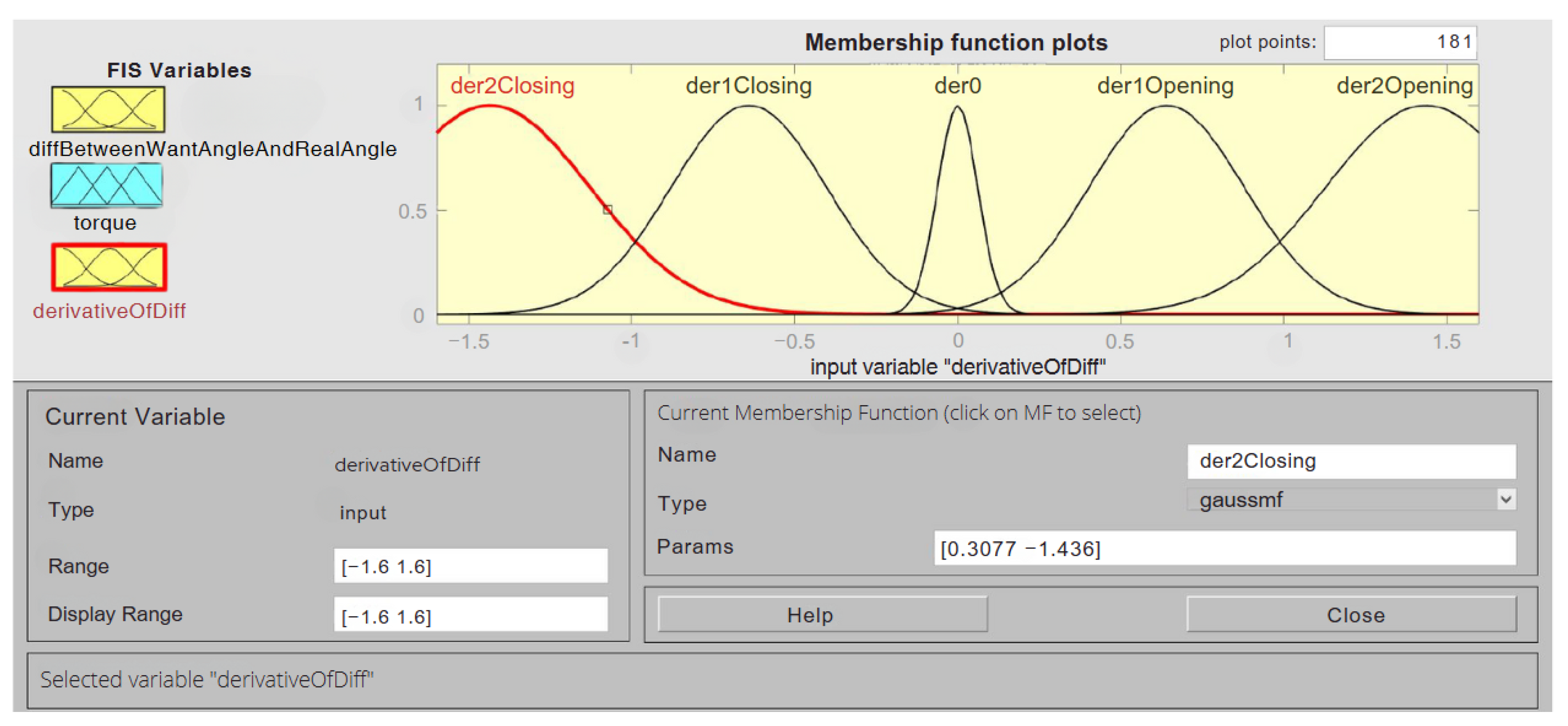
By using a second input variable, the controller prevents the movement of the finger from recklessly accelerating just because it is not yet at the desired value. For this variable, five functions were also chosen, which can be seen in
Figure 21. The functions have the same meaning as for the previous variable and are also of type “gaussmf”.
The range of this variable was set from −1.6 to 1.6. This range was selected to enable the deceleration of the hand’s movement with minimal overshoot. The width and position of each function were also chosen to ensure the most accurate and efficient finger control possible.
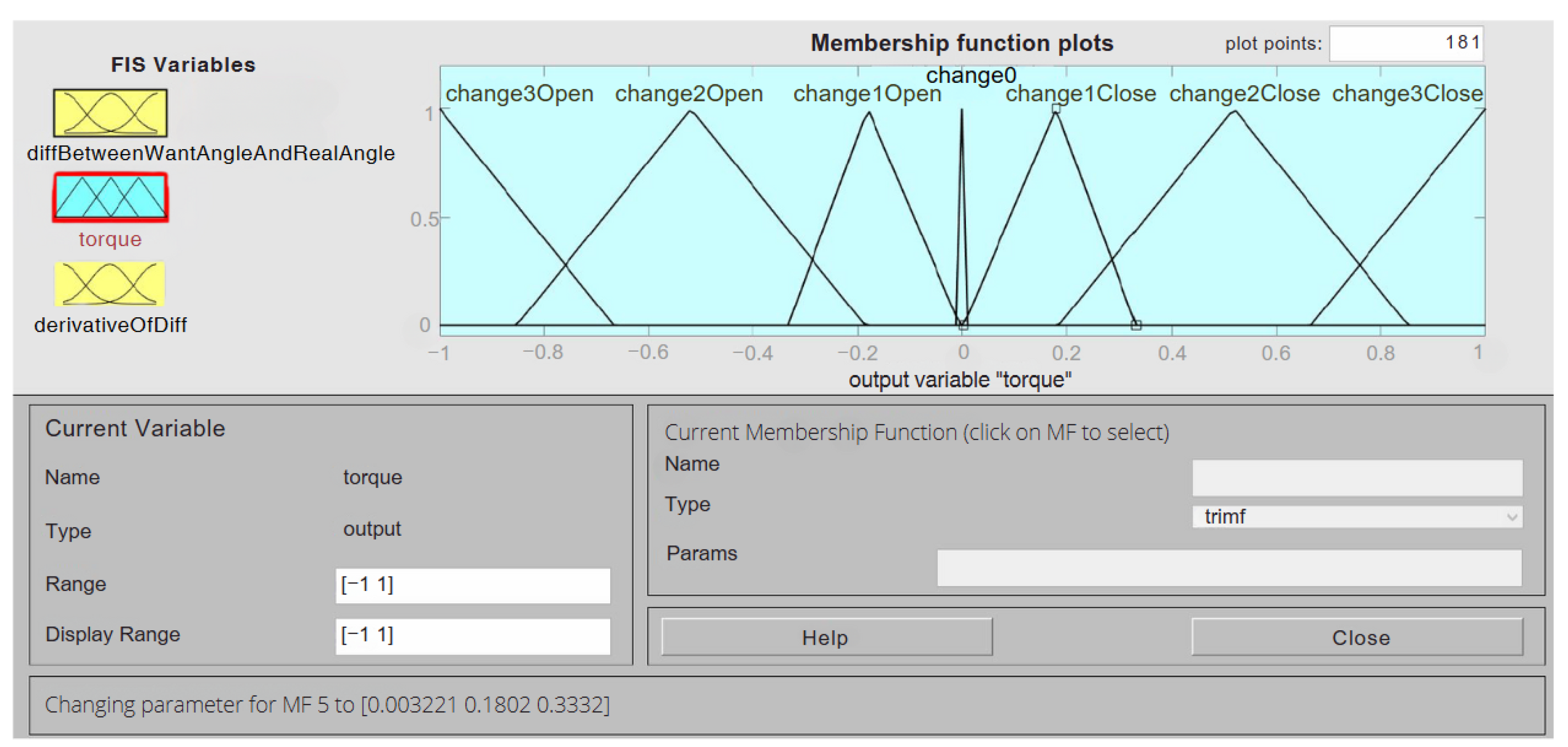
The output variable settings can be seen in
Figure 22. This variable has up to seven functions. This is in consideration of being able to define the desired change more precisely. Also, compared to the previous variables, the type of functions used here is “trimf”.
The triangular membership functions were deliberately designed to provide crisp transitions between specific output states, ensuring computational simplicity while maintaining effective control. Overlap was minimized or avoided in certain intervals to reduce ambiguity in decision-making during torque assignment. This design choice was informed by our empirical observations and experiences, which demonstrated that the fuzzy controller operates effectively with this configuration for the intended application.
The range of the output variable is from −1 to 1, and this is because this fuzzy controller has been used for all fingers, and the output torque is multiplied by the coefficient, which was already mentioned in the previous section of our work.
All these input and output variables still need to be correlated. As also mentioned earlier, fuzzy logic works on the basis of rules. These rules are written in such a way that they can be understood by every human being because they resemble human speech. In our case, this means that the rules are written in the form: if “variable1” is “value1” and “variable2” is “value2”, then “value3”. In this way, a total of 25 rules were written. Some of them are written to start the movement, others are written to speed up the movement, and vice versa; there are rules that slow down the movement. The whole fuzzy logic works on the basis of the rules written in this way, and thus, the individual fingers of our mechatronic hand are controlled based on how the rules are written in our fuzzy controller.
All 25 rules can be seen in
Table 1. The table header lists the names of two input variables and one output variable. Each combination of two input membership functions is provided with one output membership function.
The results presented in
Table 1 are identical for all fingers due to the uniformity of the simulation parameters. Therefore, no additional data tables were required to represent the system’s behavior.
5. Results
The first objective is to evaluate whether the control of individual fingers is functioning correctly and, consequently, whether the hand can accurately display the selected signs of the Slovak Sign Language alphabet. Additionally, the efficiency of the control system for the movements of the individual fingers will be assessed.
The user can just start the co-simulation and choose the sign to be demonstrated by hand. To recap, the hand can display nine characters, one of which is the starting position denoted by the number 0. These nine characters are as follows: “0, s, b, c, d, i, l, u, y”. So, after running the simulation, you only need to enter one of the above characters in the initial block, and the hand in the Adams View environment will present that sign. The simulation works in real time; if a character is changed in the initial block and confirmed, the hand will go to the position of the new character at that moment. This means that if you want to show multiple consecutive characters, you only need to change them in the initial block during the simulation. The resulting simulation also has a limitation, it cannot recognize multiple characters at once and display them consecutively, it can only display recognized characters one at a time. However, a new simulation has been created to demonstrate how this case would be possible. It operates on the principle of step blocks, with each step sending a different character at a different time. To show that the hand can display all nine characters,
Figure 23 is presented, where all the characters can be seen. Adding a new, invented character would not pose a problem. It would only need to be added to the MATLAB function described above (the character must be able to be demonstrated in accordance with our mechanical construction).
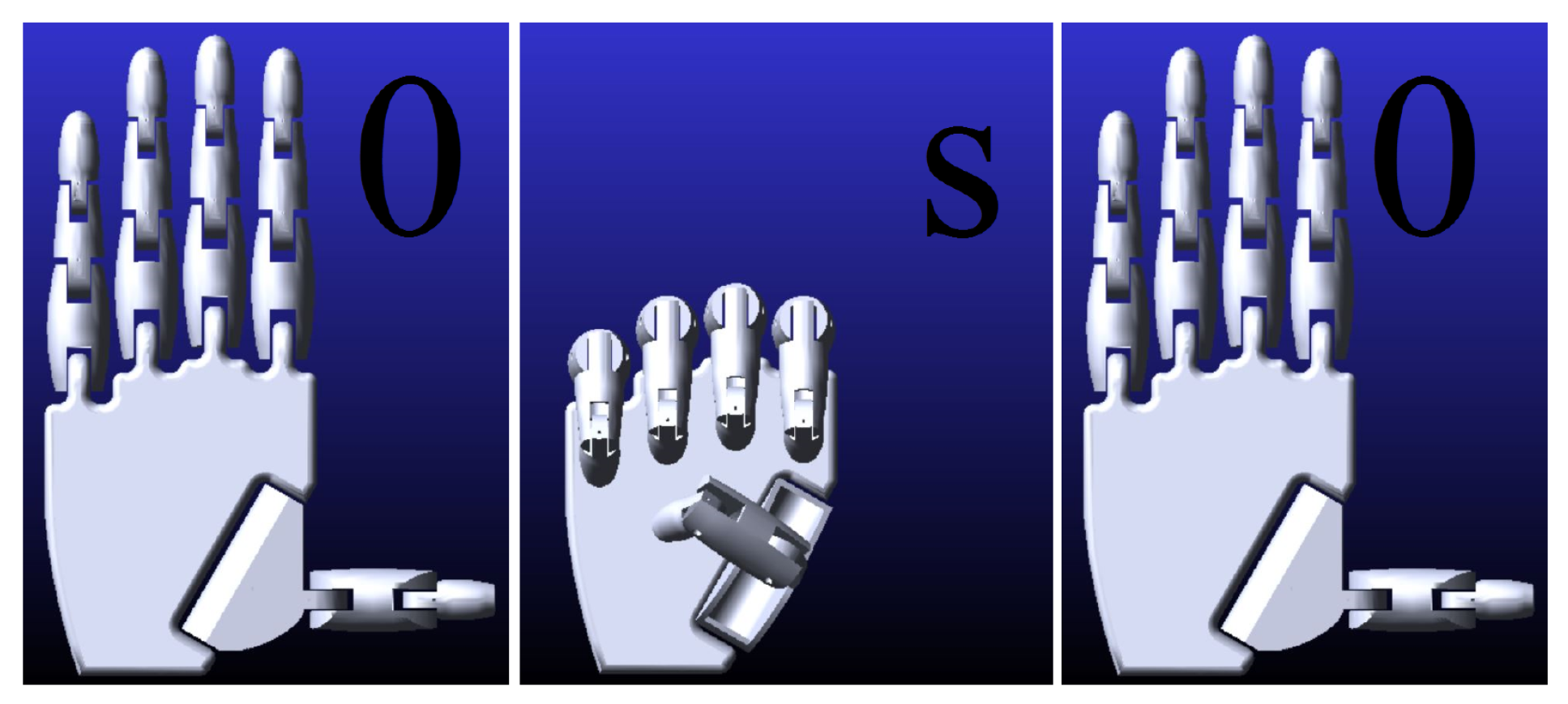
Next, the efficiency of controlling and regulating the fingers using a fuzzy controller will be presented. The first test demonstrates the case where one character is pointed to from the base position and then returned to the base position. The character “s” was chosen for this experiment, as all the fingers of the mechatronic hand are in motion during the demonstration of this sign. For better understanding,
Figure 24 is provided, where the successive positions of the fingers are shown.
The test experiment was conducted by changing the desired character to “s” at 0.1 s after starting the simulation with the desired character “0”. Then, at 1.6 s, the desired value was again changed to “0”. This process was supposed to display one character and then return to the initial position.
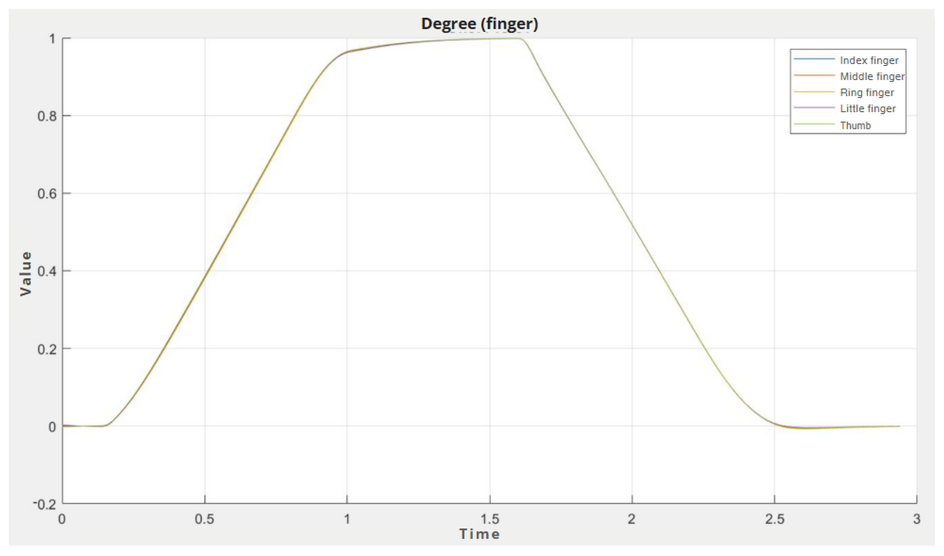
In
Figure 25, we can see the position of the individual fingers. On the X-axis is the time and on the Y-axis is a value from 0 to 1 (the value of the angle formed by the fingers). From the graph, we can see that the time it takes to reach a given sign is approximately 1.1 s, and the overshoot only occurs when moving from the palm in the direction of the initial position. The overshoot here is negligible, a maximum of 0.73 % of the total movement value.
Also, in
Figure 25, we can see that all the fingers have almost identical behavior. This phenomenon was achieved just by using the previously described constant to multiply the resulting moment from the fuzzy controller. The time in which the hand is able to show the sign is a sufficient result and also there is almost no overshoot.
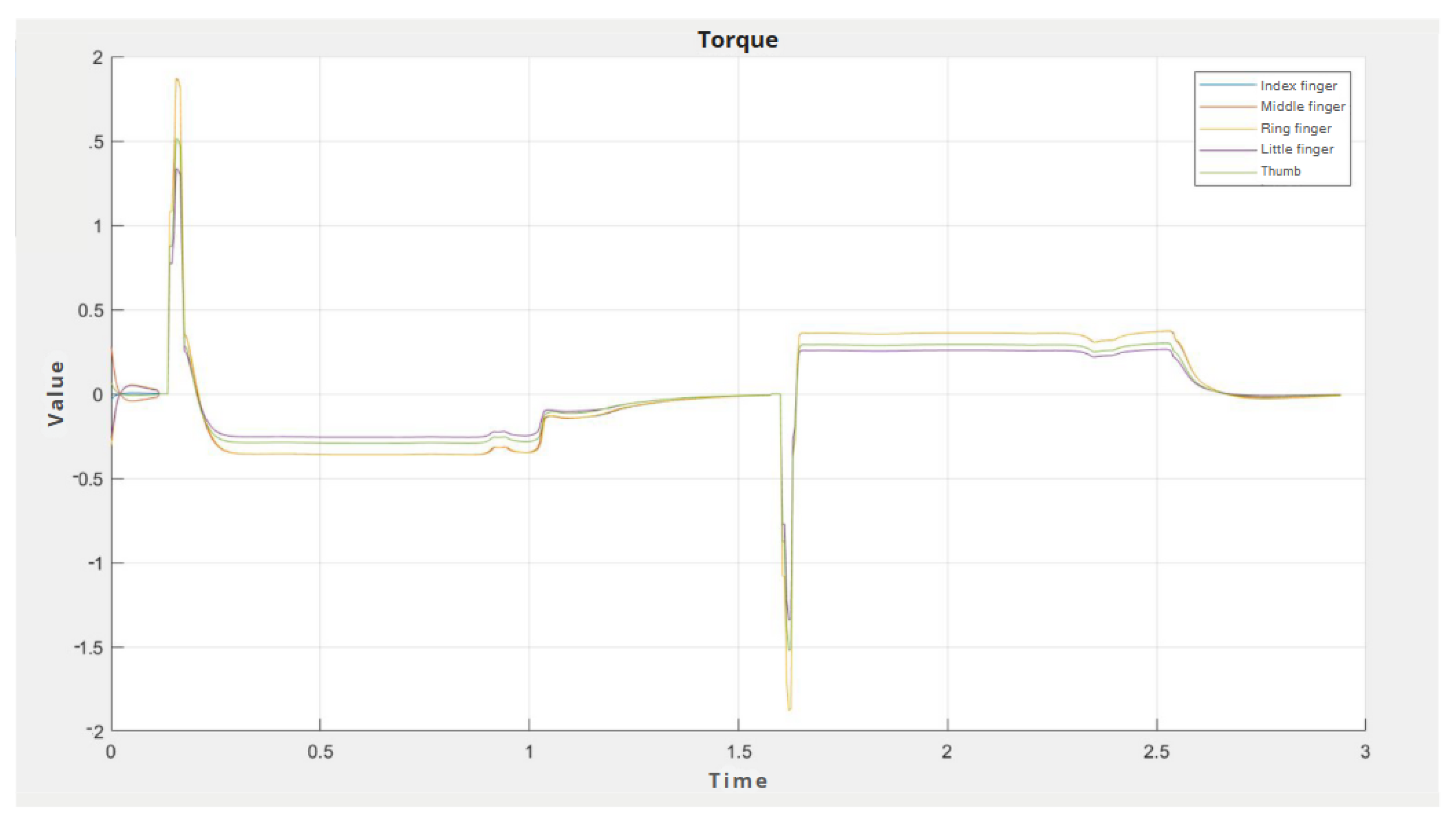
Figure 26 shows the progression of the torques by which each finger was actuated. It can be noticed that at the beginning of the movement, the torque was always high, and then the movement was slowed during the whole time. It can also be seen that the torques for the individual fingers are not as equal as they were for the finger displacement values. This is precisely because of the aforementioned coefficient that the resulting value from the fuzzy controller is multiplied by. Thus, we can see that a finger with larger dimensions and, therefore, more mass is controlled by a higher value.
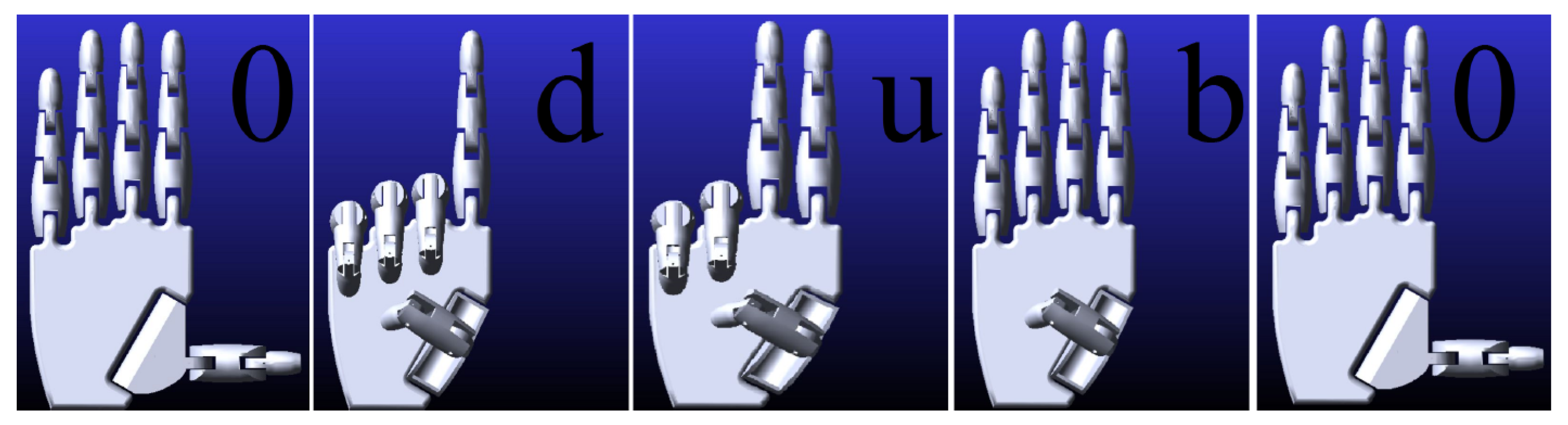
The second test was performed to demonstrate that the mechatronic hand is also capable of gesturing whole words (multiple consecutive characters). But all this assumes that the user changes the individual characters one by one. The simulation was run with the desired character “0”, which is the starting position. At time 0.5 s, the desired character was changed to the sign “d”, then at time 2 s, the input value was replaced with the character “u”. At time 4.5 s, the input value was changed again to the character “b” and finally, at time 6 s, it was replaced with the character “0” to put the hand in the start position. In a few seconds, the word “dub”, which is oak in the Slovak language, was simulated. In
Figure 27, the individual signs can be seen in the order in which they were demonstrated.
In
Figure 28, the displacements of the fingers in the second test can be seen. The graph proves that the hand did indeed make the movements that displayed the word “dub”. Times and overshoots in this case are the same as in the previous test, demonstrating that this case is also possible with our cybernetic mechatronic hand.
In the simulation, words are separated by the character “0”, ensuring a clear distinction between individual signs. This separation enhances the clarity of the gestures, making them easier to interpret. The movement of the fingers during the simulation is smooth and precise, allowing for visually clear and easily recognizable gestures. This smoothness is crucial for maintaining the readability of the signs, even for individuals who may not be accustomed to reading finger alphabets.
To further enhance the user experience, a time interval of 2.5 s per sign was defined. This interval ensures that each gesture is displayed at a pace that is both natural and easy to follow, thus allowing sufficient time for human observers to process and understand the signs. This design choice was particularly important to make the gestures accessible to a wider audience, including those unfamiliar with sign language. The simulation results demonstrated that the system effectively met its objective of accurately and clearly presenting the intended signs, showcasing the potential of the fuzzy logic controller for applications in sign language interpretation.
6. Conclusions
The subject of our work was the regulation and control of the cybernetic hand. The main goal was to create a moving 3D model of the hand and then control this model in MATLAB Simulink using a fuzzy controller. The model of a stand-alone hand is used to represent some of the signs from the Slovak Sign Language alphabet.
The work was divided into several sub-objectives. The first sub-objective was to create a 3D model in SOLIDWORKS software. In this part, a model was created based on the determined parameters. The main factor for this part was the parameter, according to which each finger should be controlled by only one motor. The next partial objective was to enrich the created 3D model from the SOLIDWORKS environment with tools and features from MSC Adams. Here, the hand model was updated so that the individual fingers could be moved. The third partial objective, which was second to last, was to create a scheme in the MATLAB Simulink environment. The scheme included the parts of the generated 3D model, as well as a user interface for inputting the required characters. The last partial objective of the work was to design a fuzzy controller. This fuzzy controller was the main part of the work because it controls the individual fingers of the hand. The controller was tuned to make the movements perform as well as possible. The best possible movements were considered to be those that did not overshoot excessively, but at the same time, the movement of the finger was not too slow.
An important achievement of this work was the integration of MSC Adams and MATLAB Simulink for co-simulation, which provided a novel approach to simulating the motion and control of robotic hands. This integration demonstrates a robust framework that can be adapted for various robotic applications, offering new possibilities for system modeling and control.
The model was tested at the end of the work. Testing showed that the result of the work meets the predefined objectives and criteria. The empirical testing of the fuzzy control system confirmed its effectiveness in managing finger movements, with practical considerations such as reducing overshoot and ensuring precise and efficient motion. The model of the cybernetic hand, with the assistance of the control scheme from the MATLAB Simulink environment, is able to demonstrate various known signs. However, only the signs that can be achieved on the constructional properties of the model can be presented. In the last testing part of the work, the quality of the control of individual finger movements was also presented, which achieved satisfactory results.
The research also highlights the potential for sign language recognition and prosthetic use. By enabling precise control and gesture recognition, the robotic hand demonstrates its relevance for human–robot interaction and assistive devices, particularly in communication and prosthetic applications. Furthermore, this work aligns with the principles of Industry 5.0 and human-centric design. The proposed cybernetic hand emphasizes inclusivity by facilitating communication through sign language and assisting individuals with disabilities to engage effectively in professional and social environments. This contribution supports the broader goals of Industry 5.0, integrating advanced technologies to empower diverse users in evolving workplaces.
In conclusion, the integration of cutting-edge simulation techniques, empirical validation, and practical applications positions this research as a meaningful contribution to the fields of robotics, assistive technology, and human–robot interaction.
In future work, we plan to move beyond simulation and focus on constructing a physical robotic hand, which allows for real-world testing and validation of the fuzzy logic controller under practical conditions. Furthermore, we aim to enhance the system’s capabilities by incorporating a wider range of gestures and alphabets, including specialized signs unique to various countries and cultures. These advancements would not only broaden the system’s applicability but also contribute to its potential as a versatile tool for diverse linguistic and cultural contexts, fostering inclusivity and accessibility in communication technologies.


