1. Introduction
Thousands of road accidents occur every year, even with the large improvement in vehicle safety technology that has happened over the last decades. Of all the traffic accidents, 10 to 20% are due to drivers with a diminished vigilance level [
1]. One of the reasons is driver inattention, monotony and fatigue.
Monotony affects the driver’s physical and cognitive sensations. The state of monotony is often associated with the nature of a monotonous task, i.e., a task that is repetitive, predictable and requires low activation of sensory perception. This can happen on long and uneventful roads, for example. Fatigue refers to a combination of symptoms, such as impaired performance and a subjective feeling of drowsiness. The term fatigue still does not have a universally accepted definition. The European Transport Safety Council states that fatigue concerns the inability or disinclination to continue an activity, generally because the activity has been going on for too long [
2]. In the driver’s context, fatigue is given as a synonym for drowsiness and tiredness and can sometimes lead to sleepiness. Both fatigue and sleepiness are characterized by a decrease in memory, reaction time, information processing, decision making and vigilance, but one can be fatigued without being sleepy [
3]. Fatigue can be caused by sleep deprivation, hot weather, or driving long distances. Alcohol (or another toxic substance) consumption also contributes to increased driver fatigue with an impact on driver detection and reaction times [
4], and consequently might contribute to accidents with serious injuries or even death for the driver and other citizens. Fatigue increases the time the driver takes to react to some dangerous event that might occur on the road. According to a study from 2015 in Europe [
5], 17% of the participating drivers admitted falling asleep at the wheel. Drowsiness provides a 7% contribution to road accidents, having caused around 13% of injuries and almost 4% of deaths.
Measuring fatigue is a significant problem because usually it is only possible to measure the outcomes of fatigue rather than the fatigue itself [
6]. Adding to that, different individuals show different symptoms to varying degrees, thus there is no concrete method of measuring the level of fatigue.
The most reliable fatigue detection techniques are based on physiological parameters such as brain waves, heart rate and breathing. However, these methods are intrusive, as they need to attach electrodes to the driver, which is uncomfortable. Other detection techniques monitor eye and gaze movement, as it has been proven that the driver’s blinking rate increases, as well as the eye closure percentage [
7]. The number of movements the driver does to accommodate also increases, as well as the number and frequency of yawns, and in some cases the drivers head might even nod. Several commercial systems were developed to detect driver fatigue signs with the use of video cameras directed to the driver’s face, connected with some device that provides strong processing power that allows detection of drowsiness in its initial stage (some examples can be found at [
8,
9]). However, its high cost, at least some hundreds of euros for a complete system, along with the desire for user privacy, are strong obstacles to the large-scale deployment of such systems.
A distinct approach to detect driver’s fatigue is to measure the driver’s behaviour by monitoring the vehicle position (e.g., lane position) and steering wheel movements, because a sleepy driver tends to make more driving mistakes [
10].
This work presents a low-cost driver assistance system that aims to detect driver fatigue and distraction episodes. The rest of the paper is organized as follows.
Section 2 presents several approaches for driver assistance systems for fatigue monitoring, including low-cost systems.
Section 3 details the prototype, which is an improvement to the one already presented by the authors in [
11] and why it did not follow the same approaches as the ones presented in
Section 2. In
Section 4 the prototype results are shown and analysed, concluding with suggestions for possible future improvements for the prototype.
2. Several Methods for Detecting Driver Fatigue
The critical issue of analysing driver fatigue and/or monotony is how to accurately detect the symptoms as early as possible. This can be achieved by using several different methods. Wang et al. defined three major categories [
6]:
The first one is to measure the driver’s current state. The most accurate way of doing it is to measure driver physiological parameters such as electroencephalogram (EEG), electrocardiogram (ECG), skin conductance, pulse beat and breathing frequency. As an example, the MINDS project (Micro Nod Detection System [
12]) proposed a head position sensor using a capacitive sensor array that aims to detect head nodding and micro-sleep events. However, using EEG or ECG sensors is not very practical, nor comfortable, for drivers. For that purpose, Rogado et al. measured the heart rate variability, as it provides information about the respiratory system [
13]. They successfully compared the use of ECG electrodes and a commercial cardiothoracic belt commonly used by sportsmen, obtaining acceptable results in a laboratory environment. An extensive evaluation of fatigue detection technologies for the road transport industry was done by Dawson et al. [
14] in the Sleep Medicine reviews journal. Not surprisingly, the most efficient monitoring devices are the ones that have less end user acceptability. For example, one of the Optalert [
15] products uses infrared reflectance oculography to detect blink frequency velocity and duration, all of these by using small sensors and LEDs mounted on the bottom of normal spectacle frames, directly pointed at the driver’s eyes.
Despite the biomedical sensor evolution, all the methods described earlier are somehow intrusive and uncomfortable, and although they have proven to work well in controlled environments, the authors have no knowledge of successful large-scale tests in real driving conditions. A non-intrusive way of detecting driver fatigue signs is by using a video camera pointed at the driver’s head: monotony can be detected by a lack of eye blink or head movement, and fatigue symptoms by high blink frequency, occurrence of yawns (by analysing the mouth shape), head nodding, etc.
The second category for measuring driver fatigue is to do it indirectly, i.e., to measure the vehicle driving parameters to detect abnormal steering wheel direction, vehicle speed or vehicle offset to lane lines, as they can be an indicator of driver drowsiness. Vehicle manufacturers have already deployed some of the vehicle offset detection systems to assist drivers, and nowadays it is common to find commercial solutions already built in vehicles that warn drivers when they are going off path, particularly in motorways. The warning can be made by either causing a vibration at the seat or at the steering wheel, at the left or right according to the lane deviation. Other driver assistance systems are available such as warning if the driver is getting too close to the vehicle.
The third category is the combination of the previous two, driver current state and vehicle driving parameters, providing more reliable results than only relying on one of them. This approach needs an effective data fusion system that can combine all the sources and obtain a correct diagnostic on the driver’s state. It has been proven that no single measure (head position, eye gaze, blink rate, etc.) is sufficiently sensitive and reliable enough to quantify driver fatigue [
16]. An interesting example of a system that combines several different parameters can be found in Bergasa’s work [
1], where a non-intrusive fully autonomous prototype was developed to determine the driver’s level of vigilance. This is achieved by monitoring five different parameters: percentage of eye closure, eye closure duration, blink frequency, face position and fixed gaze. A video camera is used together with infra-red (IR) illumination that allows the parameters to be measured in different light conditions. The data images are fed into a personal computer that calculates all the parameters. However, the system does not work well for drivers that wear glasses. Dong et al. [
17] have done an extensive review on driver monitoring systems, particularly mechanisms that combine several different sources of information about the driver’s attention. In some cases, artificial neural networks are used, where as other approaches include support vector machines and even Bayesian Networks. Some mechanisms rely on vehicle parameter data and eye closure data, while others combine driver signals (eye gaze, head orientation, heart rate). One system combines driver’s head orientation with the car surrounding map, while another combines vehicle dynamics with the driver’s facial features and body posture. More information can be found in [
17].
Non-Intrusive Fatigue and Distraction Detection Systems
Fatigue monitoring systems and distraction detection systems are already available in the market, both for the workplace environment and the vehicle (or railway) drivers (some examples can be found in [
18,
19,
20]). Most of them are based on image capture, face recognition and complex image processing for fatigue detection. The work done in face and eye detection and tracking can be further divided into two categories: passive appearance-based methods and the active infra-red (IR)-based methods. Such systems use face detection algorithms, either by using artificial neural networks or support vector machines. After detecting the upper region of the face, an eye detection algorithm must be used to detect eye blink rate, eye movement and percentage eye closure (PERCLOS). In fact, the PERCLOS method has been proven to perform well on driving simulators [
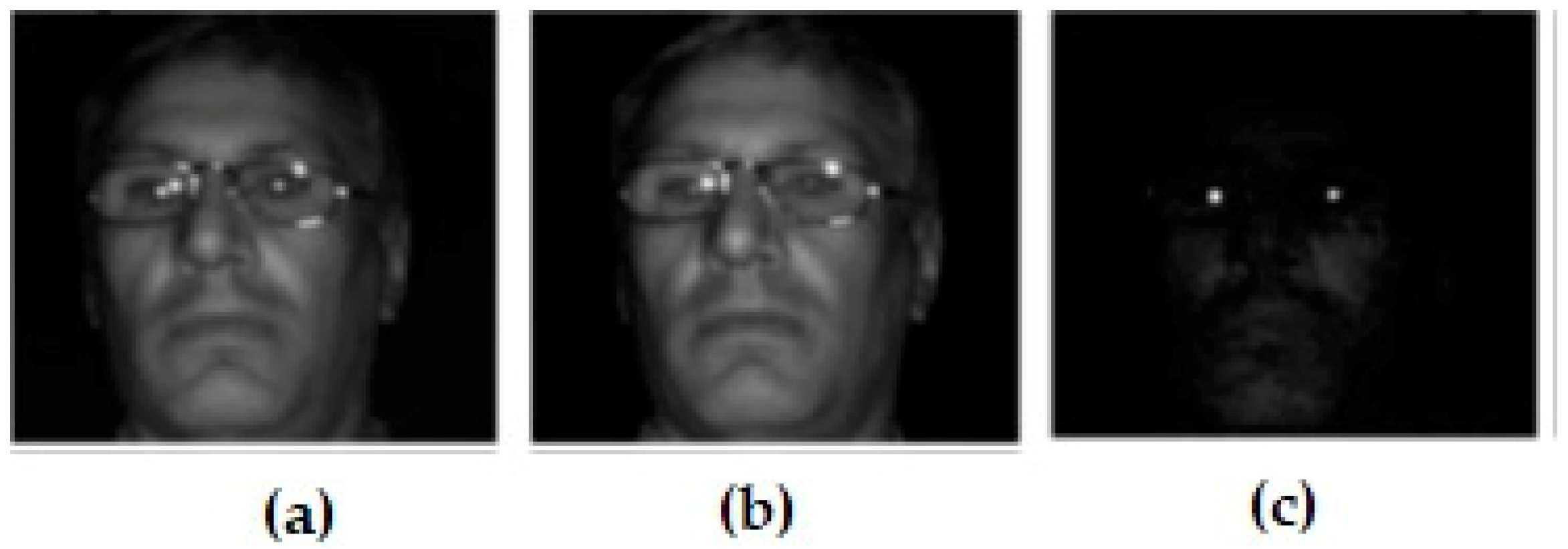
7]. The concept is to measure the proportion of total time that the driver’s eyelids are closed 80% or more. To accommodate measurements with low light conditions, active IR methods are used, with the aid of an IR spotlight pointed at the driver’s face. An example can be found in the work by Brandt et al. [
3], where the proposed system uses two webcams, an IR spotlight consisting of a grid with twenty-eight IR light emitting diodes (LED) and a personal computer (PC) with image processing algorithms. Grace et al. [
20] used the following approach to detect driver’s pupils. Two different IR illumination sources using distinct wavelengths were used. One image is obtained using an IR wavelength of 850nm and another using an 950nm wavelength. These two images are identical except for the brightness of the pupils in the image. By computing the difference between the images, the eyelids are obtained and therefore the PERCLOS can be determined, as shown in
Figure 1 [
21].
Several different projects using video cameras pointed at the driver can be found. In [
22], Chu et al. extract the mouth shape and position to detect possible yawns. The seeing machines tool [
23] in its beginning stages used two video cameras, one to the left and another to the right of the driver, and uses a real-time processor that matches specific features from both images to determine the 3D position of each feature. It also determines eye gazing, eye opening and blink rate, even if the driver is wearing glasses. To monitor eye gazing might be useful because it has been proven that fatigued drivers narrow their inspection of the outward view and spend more time looking directly ahead, reducing their inspection of the instruments and mirrors [
24]. However, even non-commercial systems are expensive, and their cost makes them inaccessible for most of the drivers.
Some controlled cost prototypes using cameras and microcontrollers were devised for driver fatigue detection. Suganya et al. used a Raspberry Pi microcontroller and infrared-sensitive camera [
25]. Palani and Kothandaraman used a regular CCD camera and a personal computer in a laboratory environment with some constraints as it does not work well for drivers with dark skin [
26].
It can be argued that some users are not comfortable with having their face being scanned, mainly due to privacy issues. To avoid cameras and biomedical sensors, some solutions are available that can detect driver behaviour related to drowsiness or fatigue. Rogado et al. used pressure sensors to detect if the drivers’ hands are on the steering wheel along with ECG electrodes [
13]. Sendra et al. used temperature sensors on the steering wheel for the same purpose [
27]. Another approach used by Sendra was to use light sensors to detect a change in the driver’s head position, as, particularly whenever the driver starts nodding off, the sensors should pick up more light.
The following
Table 1 summarizes some of the methods described in this section for monitoring the driver’s current state.
In the next section, the approach used in our work will be presented along with the obtained results.
3. To Build a Low-Cost Prototype for Driver Fatigue Detection
In this section, the several components of a low-cost system that aims to detect driver fatigue or distraction are described. The aim of this proposal is to provide a system than can be easily installed in any kind of vehicle.
3.1. Driver’s Current State Sensors
To find out if the driver has the hands on the steering wheel, several approaches can be thought of. Sendra et al. [
27] used temperature sensors along with pressure sensors. In our work a digital temperature sensor was analysed (DS18B20 Programmable Resolution 1-Wire
® Digital Thermometer) [
28] but it was not used for two reasons: it was too slow in updating the temperature values, and it was difficult to avoid false alarm situations whenever the temperature threshold was exceeded due to a reason other than the drivers hand being on the steering wheel, e.g., if the steering wheel had a long exposure to sunlight. A pressure sensor was also thought of, similar to the one used by Rogado et al. [
13], a force sensing resistor [
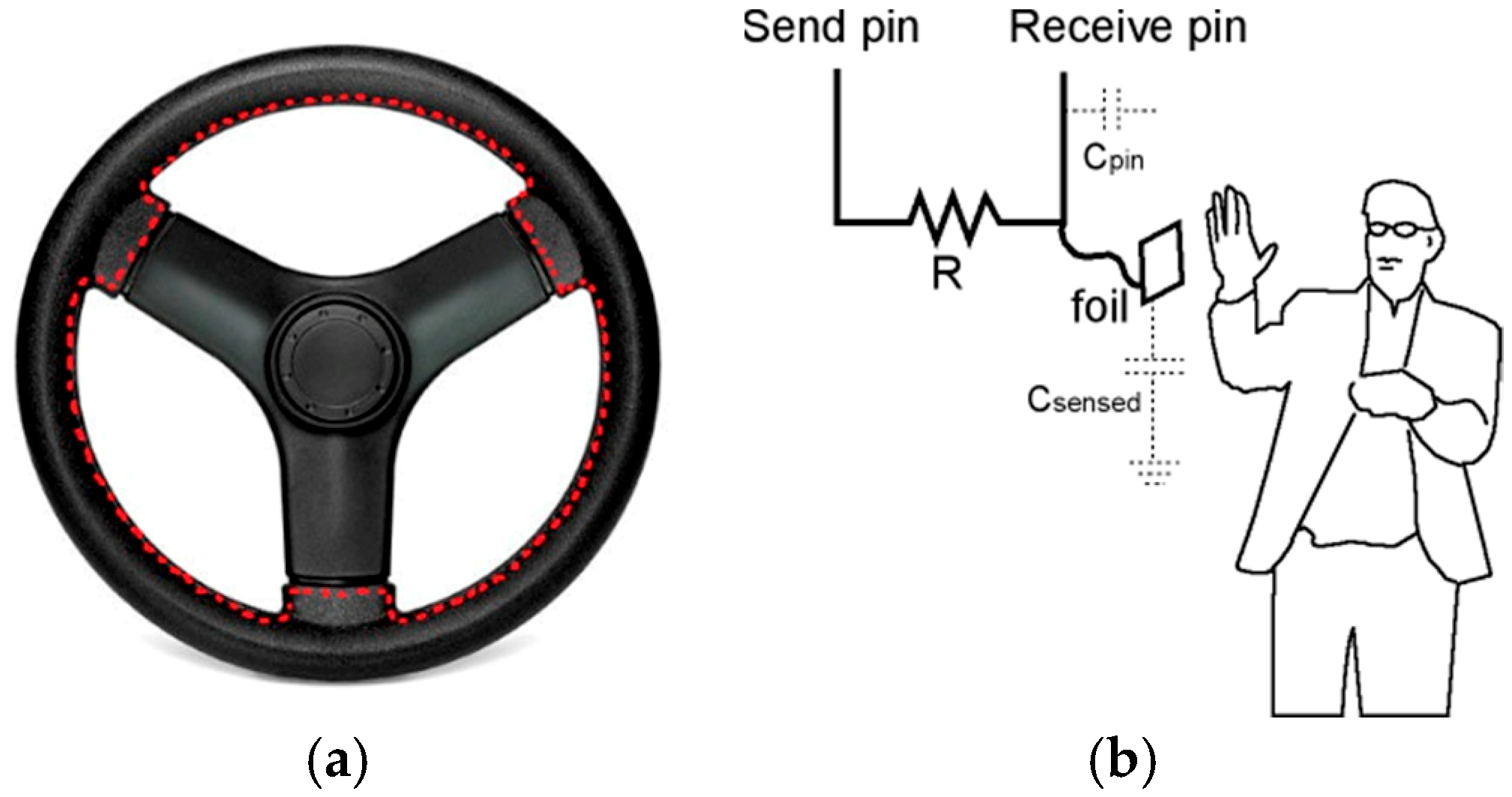
29], but the option was discarded because drivers can place their hands in different parts of the steering wheel at different times, and this meant that the choice of the pressure sensor spot on the steering wheel was troublesome. The decision was to use a capacitive sensor that measures electric charges in the driver hands that are placed on the steering wheel. The original steering wheel seam was replaced by a capacitive sensor wire across the whole steering wheel, as is seen in
Figure 2a. Using this approach, it is easy to detect whenever a driver finger (or hand) is on the steering wheel, having also the ability to differentiate between having one or both driver’s hands on the steering wheel, as depicted in
Figure 2b [
30].
For detection of the drivers’ head position, a photodiode or light dependent resistor (LDR) is an inexpensive possibility, therefore it was the choice of Sendra’s team [
27]. Laboratory tests, however, have proven that a LDR [
31] is inefficient for days with strong solar exposure, and on the opposite side the photodiode [
32] showed weak results for low light environments (i.e., during the night). A more reliable solution is to use an infra-red emitter and receiver [
33], which can detect the position of the driver’s head, with or without sunlight presence. Care was taken to correctly place the set, and after a few tests, it was found that the better position would be on top of the headset of the driver’s seat.
3.2. Vehicle Driving Parameters Sensors
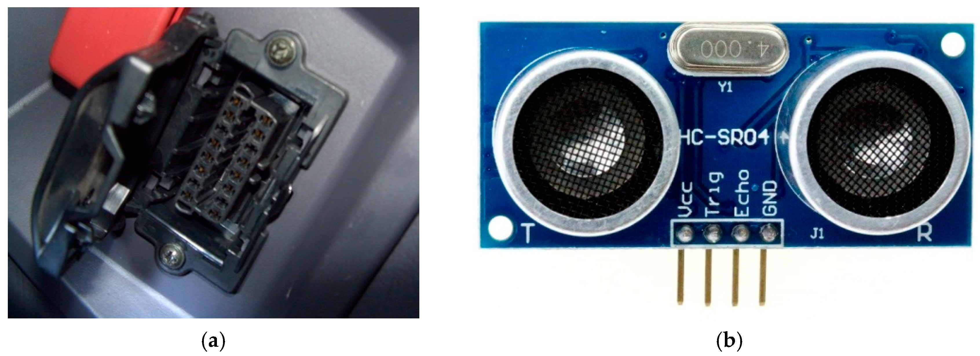
As for the vehicle driving parameters, one important parameter to measure is the vehicle’s current speed. It may be used for several purposes, including the avoidance of false alarms that might occur if the driver releases the steering wheel, but the vehicle is stopped. As all vehicles manufactured after 1996 provide an on-board diagnostics (OBDII) interface with the vehicle’s on-board CPU, it is possible to connect the microcontroller to the vehicle and find vehicle parameters including speed and throttle position, amongst others. In
Figure 3a an OBDII connector is shown.
Another sensor was also added to the prototype, to make the prototype more attractive for possible users: a blind spot detector was designed using an ultrasound sensor. It is a small increase to the prototype cost but a large increase in driver safety, since it can warn the driver of an obstacle presence in its blind spot up to a 4-meter distance (refer to
Figure 3b). Besides detecting other vehicles, it can be used to detect an abnormal driving situation.
3.3. Driver Interaction Sensors and Microcontroller Choice
In the first implementation of the prototype by Dantas and Meireles [
11], a simple buzzer was used to alert the driver to an abnormal situation, such as a long period of time without having the hand at the steering wheel or whenever the driver’s head started nodding. Different audible frequencies were used to distinguish the alert type. A push button was provided for the driver to turn off the alarm, being also used in the process of fine-tuning the prototype according to each driver. A LED was used to alert the driver whenever an obstacle was present in its blind-spot. Using a buzzer proved not be the most adequate way to wake up the driver, therefore the buzzer was replaced by some small low-cost vibration motors, inserted inside the steering wheel [
36].
Several inexpensive microcontrollers are available in the market. For this system, the option was to use a small electronic board Arduino Uno, based on the ATmega328p microcontroller. It is simple to program (thus reducing the cost on the programming side) and it provides 14 digital input/outputs as well as 6 analogic inputs. It can be powered from batteries and it also provides AC/DC and USB connectors [
37].
3.4. NoSleep Prototype Demonstrator
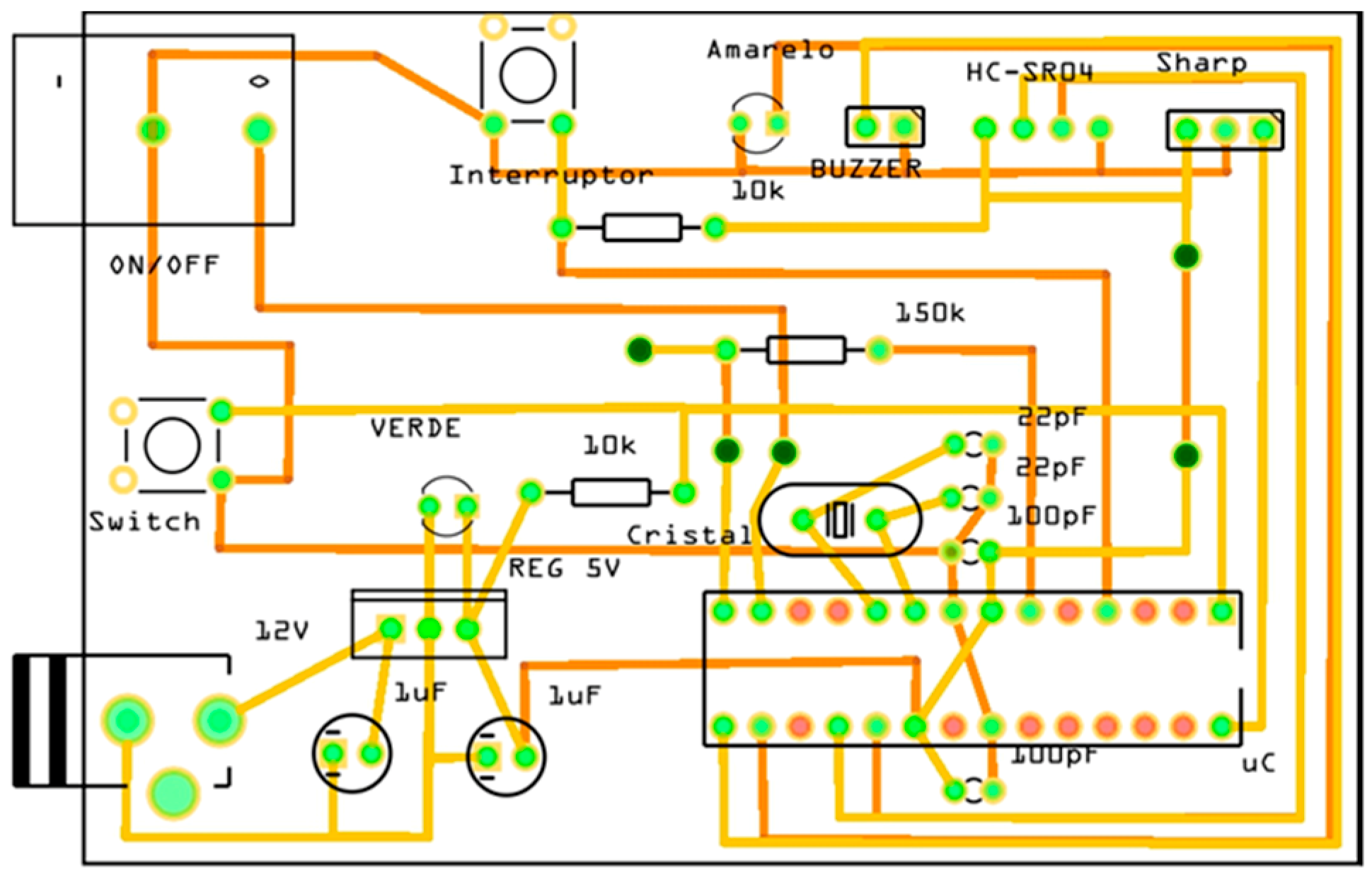
The next step was to build a demonstrator and give it a name. The prototype was named NoSleep and was built in the electronics laboratory, using a real driver seat and steering wheel. After several development stages, a printed circuit board (PCB) was built, as shown in
Figure 4.
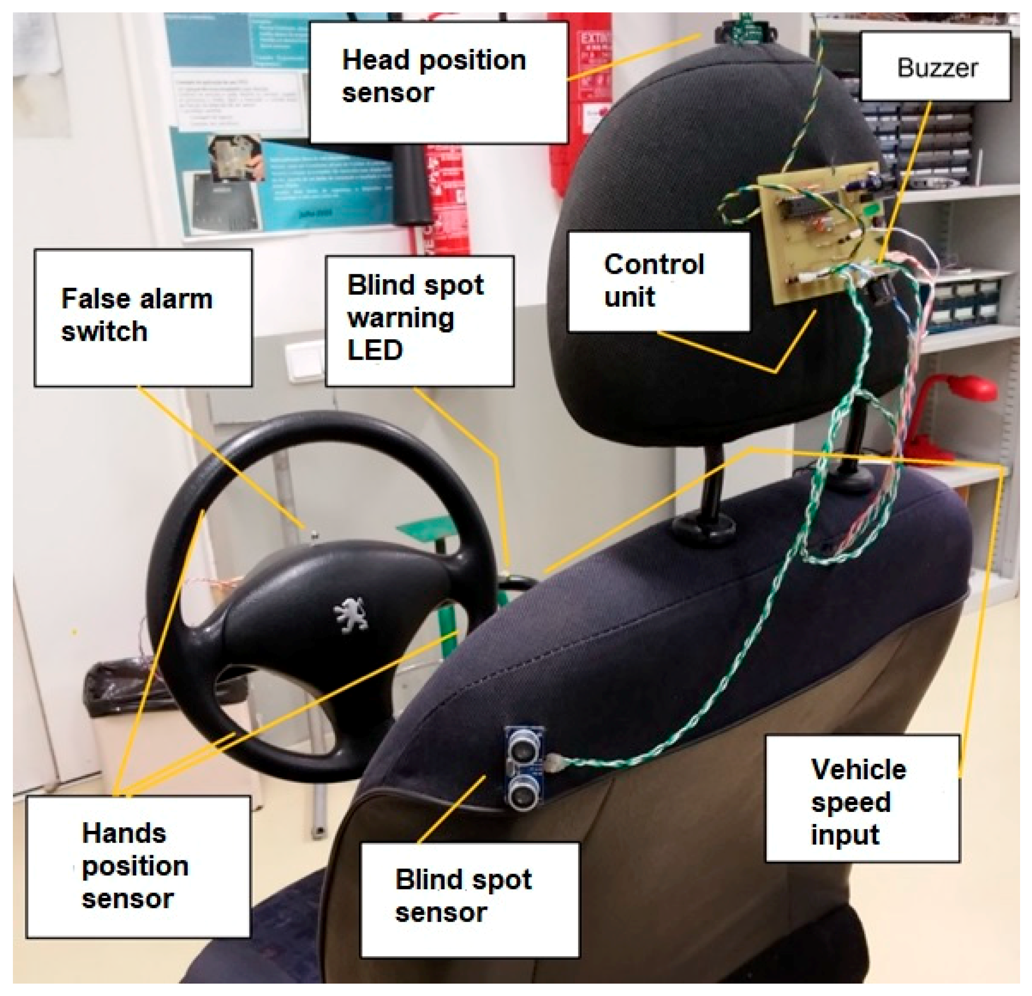
The laboratory prototype can be seen in
Figure 5, where the control unit is shown outside the headrest for demonstration purposes, as it should be placed on the inside. As this is a prototype in the lab, the blind spot sensor is placed on the driver seat, instead of being placed near the left rear-view mirror. The head position sensor is stitched to the top of the head rest and all the other sensors and the false alarm switch are placed on the steering wheel. For the demonstration prototype, the OBD-II connector was replaced by a switch indicating if the vehicle is moving or is stopped. Most of the cabling was passed on the inside of the driver seat and the steering wheel support.
3.5. Sensor Calibration and Testing
The NoSleep system monitors four different sensors: vehicle speed, drivers’ head and hand position and blind spot detector. After several tests, it was decided that the vehicle speed is measured at the rate of 2 samples per second, while the remaining sensors are sampled 10 times per second.
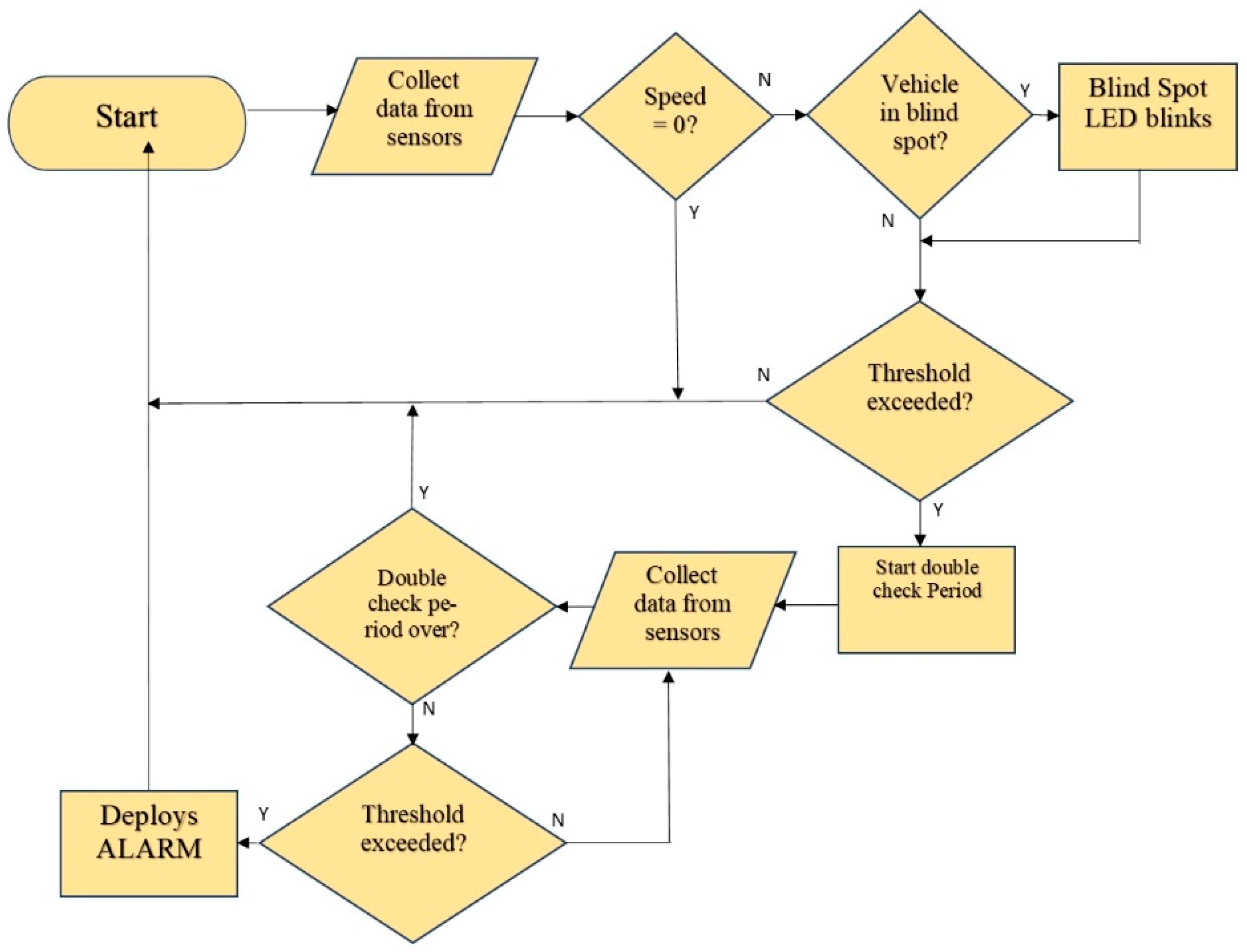
In case an abnormal situation occurs, such as the drivers’ hands are not detected on the steering wheel, or the driver head position value detects the driver is nodding, the system first confirms if the vehicle is moving. If so, if it receives another confirmation of such a situation occurring within a time span of 1 s (adjustable period), it alerts the driver via the buzzer placed in the headrest. A false alarm switch can be pushed at any time by the driver, which turns off the alarm for a 10 s duration. This is done via interrupt and therefore is not shown in the flowchart of
Figure 6 that describes the entire procedure.
Several tests were conducted in different environments with distinct light conditions, to define the thresholds levels for each sensor. The headrest sensor is the one that presented some difficulties, as its position and calibration may depend on the driver’s height. All the other sensors were tested with different drivers with successful results in what concerns the sensors being activated, therefore the prototype serves its purpose.
4. Conclusions
This work presented a non-intrusive, low-cost prototype, that respects driver’s privacy, as it does not use video cameras. The NoSleep prototype aims to detect driver fatigue symptoms and provides an improvement to the system presented by Sendra et al. in [
27], as it responds to environments with different light and temperature conditions, which posed a problem with the solutions used in Sendra’s project. However, both Sendra’s and NoSleep prototypes do not respond well if the driver falls asleep with one hand at the steering wheel, or if their head nods off but still blocks the head sensor. Also, the prototype does not detect the intermediate states where the driver might still be half awake but lacks concentration. Tests showed that the use of a buzzer was not a good option and therefore it was replaced by three small vibration motors, placed inside the steering wheel, similar to on-board systems that can already be found in some vehicles. To keep the cost of such a driver assistance system as low as possible, while maintaining a fair level of reliability, was the goal of this work. Off the shelf component prices from several different online vendors were considered [
38,
39], including the microcontroller, several sensors, electronic components (resistors, capacitors, LEDs, etc.), the vibration motors, batteries, and connectors. The cost of the OBD-II connector and the cost of making the PCB board were also considered [
40].
Table 2 summarizes the components used in the NoSleep prototype and their cost.
Assuming that discounts are available for a large number of units (more than one thousand) the final price of the NoSleep driver assistance system can be kept below 30€.


