Next Article in Journal
Development of Focusing Plasma Mirrors for Ultraintense Laser-Driven Particle and Radiation Sources
Next Article in Special Issue
Facilities in Quantum Beam Science
Previous Article in Journal
Novel Single-Shot Diagnostics for Electrons from Laser-Plasma Interaction at SPARC_LAB
Previous Article in Special Issue
Materials and Life Science Experimental Facility at the Japan Proton Accelerator Research Complex III: Neutron Devices and Computational and Sample Environments
 
 
qubs-logo
Article Menu

Article Menu

Review

Materials and Life Science Experimental Facility (MLF) at the Japan Proton Accelerator Research Complex II: Neutron Scattering Instruments

by
Kenji Nakajima
1,*,
Yukinobu Kawakita
1,
Shinichi Itoh
1,2,3,
Jun Abe
4,
Kazuya Aizawa
1,
Hiroyuki Aoki
1,
Hitoshi Endo
1,2,3,
Masaki Fujita
5,
Kenichi Funakoshi
4,
Wu Gong
6,
Masahide Harada
1,
Stefanus Harjo
1,
Takanori Hattori
1,
Masahiro Hino
7,
Takashi Honda
1,2,
Akinori Hoshikawa
8,
Kazutaka Ikeda
1,2,3,
Takashi Ino
1,2,3,
Toru Ishigaki
8,
Yoshihisa Ishikawa
1,2,3,
Hiroki Iwase
4,
Tetsuya Kai
1,
Ryoichi Kajimoto
1,
Takashi Kamiyama
1,2,3,
Naokatsu Kaneko
1,2,
Daichi Kawana
9,
Seiko Ohira-Kawamura
1,
Takuro Kawasaki
1,
Atsushi Kimura
1,10,
Ryoji Kiyanagi
1,
Kenji Kojima
1,2,3,
Katsuhiro Kusaka
8,
Sanghyun Lee
1,2,
Shinichi Machida
4,
Takatsugu Masuda
9,
Kenji Mishima
1,2,3,
Koji Mitamura
11,12,
Mitsutaka Nakamura
1,
Shoji Nakamura
1,10,
Akiko Nakao
4,
Tatsuro Oda
7,
Takashi Ohhara
1,
Kazuki Ohishi
4,
Hidetoshi Ohshita
1,2,
Kenichi Oikawa
1,
Toshiya Otomo
1,2,3,
Asami Sano-Furukawa
1,
Kaoru Shibata
1,
Takenao Shinohara
1,
Kazuhiko Soyama
1,
Jun-ichi Suzuki
4,
Kentaro Suzuya
1,
Atsushi Takahara
11,12,
Shin-ichi Takata
1,
Masayasu Takeda
13,
Yosuke Toh
1,10,
Shuki Torii
1,2,
Naoya Torikai
2,14,
Norifumi L. Yamada
1,2,3,
Taro Yamada
8,
Dai Yamazaki
1,
Tetsuya Yokoo
1,2,3,
Masao Yonemura
1,2,3 and
Hideki Yoshizawa
9
add Show full author list remove Hide full author list
1
Materials & Life Science Division, J-PARC Center, Tokai, Ibaraki 319-1195, Japan
2
Institute of Materials Structure Science, High Energy Accelerator Research Organization, Tsukuba, Ibaraki 305-0801, Japan
3
Department of Materials Structure Science, SOKENDAI (the Graduate University for Advanced Studies), Tokai, Naka, Ibaraki 319-1106, Japan
4
Neutron Science and Technology Center, Comprehensive Research Organization for Science and Society, Tokai, Naka, Ibaraki 319-1106, Japan
5
Institute for Materials Research, Tohoku University, Katahira, Aoba-ku, Sendai 980-5877, Japan
6
Center for Elements Strategy Initiative for Structural Materials, Kyoto University, Yoshida-honmachi, Sakyo-ku, Kyoto 606-8501, Japan
7
Research Reactor Institute, Kyoto University, Kumatori, Sennan, Osaka 590-0494, Japan
8
Frontier Research Center for Applied Atomic Sciences, Ibaraki University, Tokai, Naka, Ibaraki 319-1106, Japan
9
Neutron Science Laboratory, the Institute for Solid State Physics, the University of Tokyo, Tokai, Naka, Ibaraki 319-1106, Japan
10
Nuclear Science and Engineering Center, Japan Atomic Energy Agency, Tokai, Naka, Ibaraki 319-1195, Japan
11
JST ERATO, Takahara Soft Interfaces Project, Fukuoka, Fukuoka 819-0395, Japan
12
Institute for Materials Chemistry and Engineering, Kyushu University, Fukuoka, Fukuoka 819-0395, Japan
13
Materials Sciences Research Center, Japan Atomic Energy Agency, Tokai, Naka, Ibaraki 319-1195, Japan
14
Graduate School of Regional Innovation Studies, Mie University, Tsu, Mie 514-8507, Japan
*
Author to whom correspondence should be addressed.
Quantum Beam Sci. 2017, 1(3), 9; https://doi.org/10.3390/qubs1030009
Submission received: 28 June 2017 / Revised: 25 October 2017 / Accepted: 7 November 2017 / Published: 17 November 2017
(This article belongs to the Collection Facilities)

Abstract

:
The neutron instruments suite, installed at the spallation neutron source of the Materials and Life Science Experimental Facility (MLF) at the Japan Proton Accelerator Research Complex (J-PARC), is reviewed. MLF has 23 neutron beam ports and 21 instruments are in operation for user programs or are under commissioning. A unique and challenging instrumental suite in MLF has been realized via combination of a high-performance neutron source, optimized for neutron scattering, and unique instruments using cutting-edge technologies. All instruments are/will serve in world-leading investigations in a broad range of fields, from fundamental physics to industrial applications. In this review, overviews, characteristic features, and typical applications of the individual instruments are mentioned.

1. Introduction

The spallation neutron source at the Materials and Life Science Facility (MLF) is one of the most advanced and one of the most powerful neutron sources in the world. In two experimental halls at MLF (Figure 1), 20 neutron instruments are in operation and one is under commissioning (Table 1). These are various types of instruments to serve various fields of investigations in which neutron scattering techniques can play a significant role.
Each of our instruments is unique, state-of-the-art, and distinguished from other instruments that have existed thus far. They are realized by a combination of the high performance of our neutron source and new technologies.
The characteristics of our neutron source are one of the most important key factors contributing to their uniqueness and the high performance of the instruments. When the Japan Proton Accelerator Research Complex (J-PARC) project was launched, individuals from the Japanese neutron science community got together and intensively discussed possible neutron instruments at the high-intensity spallation neutron source [1]. The results of these discussions became the foundation of the Grand Design, a list of instruments to be built at MLF, which were established by the Japanese Society for Neutron Science. Over the course of the discussions, through dialogue with the neutron source group, the unique features of our neutron source were determined, e.g., (1) all of moderators are cryogenic (supercritical H2) without ambient ones; (2) the majority of the beam ports needed to view a coupled moderator; and (3) the pulse repetition rate needed to be 25 Hz. In particular, a coupled moderator is one of key features MLF. It was obvious that a fairly high neutron flux was expected to be obtained using the new 1 MW-class spallation source, which we have not yet experienced. However, we were not satisfied with this expectation, and attempted to maximize the beam flux further. The answer to this requirement is that our coupled moderator, which provides a maximum intensity at the neutron source at MLF. The disadvantage of this type of moderator is that the pulse shape becomes rather broad and strongly asymmetric, especially in the lower energy region. In spite of this fact, almost half of the neutron instruments at MLF have a coupled moderator. It should be noted that three of them are chopper spectrometers and one is a near-backscattering spectrometer, for which a sharp pulse source was considered to be indispensable. On the other hand, another aspect of the needed neutron source, which prefers a finer and symmetric pulse shape, resulted in decoupled and decoupled poison moderators. With its fine pulse shape, the new Ag-In-Cd decoupler contributes to the high performance of our high resolution diffractometers. SuperHRPD surpassed the world’s finest achieved resolution record, even at the very early stages of MLF. The characteristics of our neutron source allow the neutron instruments to attempt new methods, new technologies, and new devices, as described in the following sections.
In addition to utilizing the advantages of our advanced neutron source, we have been attempting to involve new techniques, as well as new ideas, to maximize the performance of our instruments, some which were considered to be challenging at the time but are now common. From the beginning of the J-PARC project, we decided to employ an event data-recording method, instead of histogram recording, which was the standard method over the long history of pulsed neutron source instruments [2,3]. All software suites, data acquisition systems, and instruments were designed to fully adapt to the event recording method, and this idea enabled us to perform multi-incident energy measurements using chopper spectrometers [4], stroboscopic measurements using diffractometers [5], and even magnetic field imaging using our imaging instruments [6,7]. The pulse manipulation techniques gave us another success; multi-incident energy measurements using a repetition rate multiplication (RRM) technique [8] were realized using 4D-Space Access Neutron Spectrometer (4SEASONS) as the world’s first demonstration [4], and this method became quite common for chopper spectrometers at modern pulsed neutron facilities around the world. Pulse-shaping technology using a pulse shaping chopper located near a source was employed at the Cold-Neutron Disk-Chopper Spectrometer AMATERAS [9] around the same time that it was performed at CNCS at the Spallation Neutron Source (SNS) (Oak Ridge National Laboratory, Oak Ridge, TN, USA) [10] and LET at ISIS Neutron and Muon Source (Rutherford Appleton Laboratory, Didcot, UK) [11]. These three chopper spectrometers were the world’s first cases of using a pulse-shaping chopper to control resolution. DNA was the world’s first example of a practical realization of the wave-length frame multiplication technique, which permits pulse-shaping, even on an indirect geometry spectrometer [12]. Another interesting challenge is the neutron Brillouin scattering (NBS) capability, which is being developed as an option at the High Resolution Chopper Spectrometer (HRC) to overcome the kinematic constraints of neutron spectroscopy [13], and it has been confirmed that the performance is better than those of existing NBS-dedicated instruments. We also attempted to use many other technologies, such as wavelength shifting fiber scintillators, elliptic guide geometry, pulse neutron adapted magnetic lens, etc., which provided a breakthrough for our instruments to realize the performance that would be expected by users. Although some of these breakthroughs are commonplace components in many instruments at many facilities now, they were challenging when we started pioneering work on them.
On the basis of these technological developments, neutron applications have been widely extended by accompanying a kind of phase change. For example, diffraction measurements are trying not only passive measurement with static conditions at specific temperatures, but also active measurements, such as stroboscopic measurements under elevating temperatures passing over phase transitions, alternating external fields, in situ stress measurements under a loading process, and so on. Inelastic scattering measurements have been drastically changed from a pin-point measurement in specific regions of momentum and energy transfers to observations covering an entire range using several energy resolutions. Materials to be measured have gradually changed from pure materials, from which fundamental aspects can be extracted, to composite materials, which can be used in industrial application. Highly-intense beams open new research fields, such as neutron bio-crystallography and high-pressure geo-sciences. The development of software is always key in supporting new experimental techniques and in developing new analysis methods.
Nine years have passed since we produced the first neutron beam at MLF, in May, 2008. Now, 21 of 23 beam ports are presently available. We are always attempting to realize cutting-edge instrumentation. In April 2015, our newest instrument, the Energy Resolved Neutron Imaging System RADEN at BL22, was released in the user program. RADEN is the world’s first dedicated energy-resolved imaging instrument, and provides full-scale possibilities for resonance absorption, Bragg edge imaging, and magnetic field imaging. The Village of Neutron Resonance Spin Echo Spectrometers VIN ROSE at BL06 is an ambitious spin echo spectrometer suite composed of a neutron-resonance-type spectrometer and a modulated intensity by zero effort type spin-echo spectrometer. The spectrometer has been partly open to the user program since the latter half of 2017. Moreover, a new chopper spectrometer, POLANO (Polarized Neutron Spectrometer), is under commission at BL23. POLANO is a dedicated polarized neutron inelastic instrument, in which we are employing modern polarization techniques.
Our neutron instruments at MLF are operated by four different groups:
(i)
Spectroscopy group (inelastic instruments)
4SEASONS: 4D-Space Access Neutron Spectrometer [14]
HRC: High Resolution Chopper Spectrometer [15,16]
AMATERAS: Cold-Neutron Disk-Chopper Spectrometer [9]
POLANO: Polarized Neutron Spectrometer [17,18,19]
DNA: Biomolecular Dynamics Spectrometer [12]
VIN ROSE: Village of Neutron Resonance Spin Echo Spectrometers [20].
(ii)
Crystal-structure group (diffractometers)
SuperHRPD: Super High-Resolution Powder Diffractometer [21]
SPICA: Special Environment Powder Diffractometer [22]
iMATERIA: IBARAKI Materials Design Diffractometer (Versatile Neutron Diffractometer) [23]
PLANET: High-Pressure Neutron Diffractometer [24]
TAKUMI: E Engineering Materials Diffractometer [25,26]
iBIX: IBARAKI Biological Crystal Diffractometer [27,28]
SENJU: Extreme Environment Single-crystal Neutron Diffractometer [29].
(iii)
Nano-structure group (small-angle neutron scattering instrument, reflectometers, and total scattering instruments)
TAIKAN: Small- and Wide-angle Neutron Scattering Instrument [30]
SOFIA: Soft Interface Analyzer [31,32]
SHARAKU: Polarized Neutron Reflectometer [33]
NOVA: High-Intensity Total Diffractometer.
(iv)
Pulsed neutron application group (other than neutron scattering instruments (beamlines for neutronics studies, fundamental physics, prompt gamma-ray analysis, versatile test port, and neutron imaging))
ANNRI: Accurate Neutron-Nucleus Reaction measurement Instrument [34]
NOP: Neutron Optics and Physic [35]
NOBORU: NeutrOn Beam-line for Observation and Research Use [36]
RADEN: Energy Resolved Neutron Imaging System [37].
In this review, we overview these 21 instruments at MLF, according to these 4 groups. In addition, we review the typical scientific outputs from these instruments.

2. Spectroscopy Group Instruments

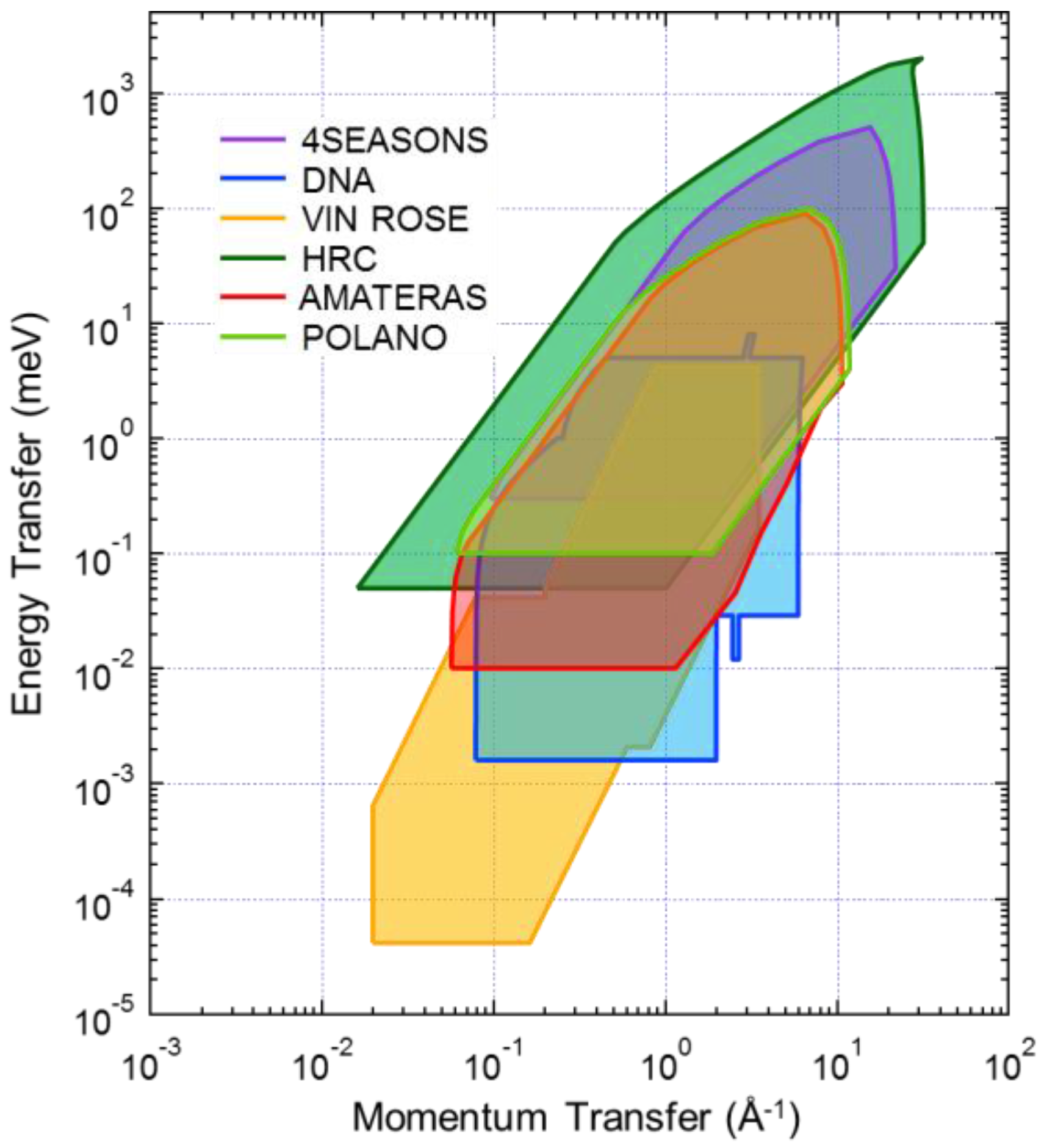
The MLF Spectroscopy Group consists of six instruments for inelastic and quasi-elastic neutron scattering in MLF [38]. 4SEASONS, HRC, AMATERAS, and POLANO are direct geometry spectrometers; 4SEASONS, HRC, and POLANO use Fermi choppers to monochromate incident neutron beams, while AMATERAS used a combination of disk choppers. Among these spectrometers, POLANO can be used with polarized neutrons. Its construction was completed recently, and it has been in the commissioning phase since 2017. DNA is a near-back scattering spectrometer with a pulse-shaping chopper. Measurements with micro-eV resolution can be performed using this instrument. Neutron spin echo (NSE) spectrometer VIN ROSE can access even slower dynamics. This spectrometer includes two instruments of the Modulated Intensity with Zero Effort (MIEZE) type and Neutron Resonance Spin Echo (NRSE) type. They are under commissioning and are expected to be open to the user program in 2017. Combinations of these instruments in MLF allows for the study of dynamics in diverse fields, including solid state physics, amorphous materials and liquids, soft and biological matters, as well as industrial applications such as tire rubbers and battery materials (Figure 2).
As for the operational sides of the instruments, AMATERAS is a Japan Atomic Energy Agency (JAEA) beamline operated by JAEA staff, while 4SEASONS and DNA are the Public Beamlines operated by JAEA and the registered institution for public use, Comprehensive Research Organization for Science and Society (CROSS). HRC, POLANO, and VIN ROSE are operated by the High Energy Accelerator Research Organization (KEK) in collaboration with the University of Tokyo, Tohoku University, and Kyoto University, respectively, under KEK Inter-University Research Program. Despite the differences in their operating policies, there is no restriction on user access, and the knowledge obtained by these instruments is shared for improving instrument performance through moderate collaboration among the institutions that run them.

2.1. 4D-Space Access Neutron Spectrometer, 4SEASONS

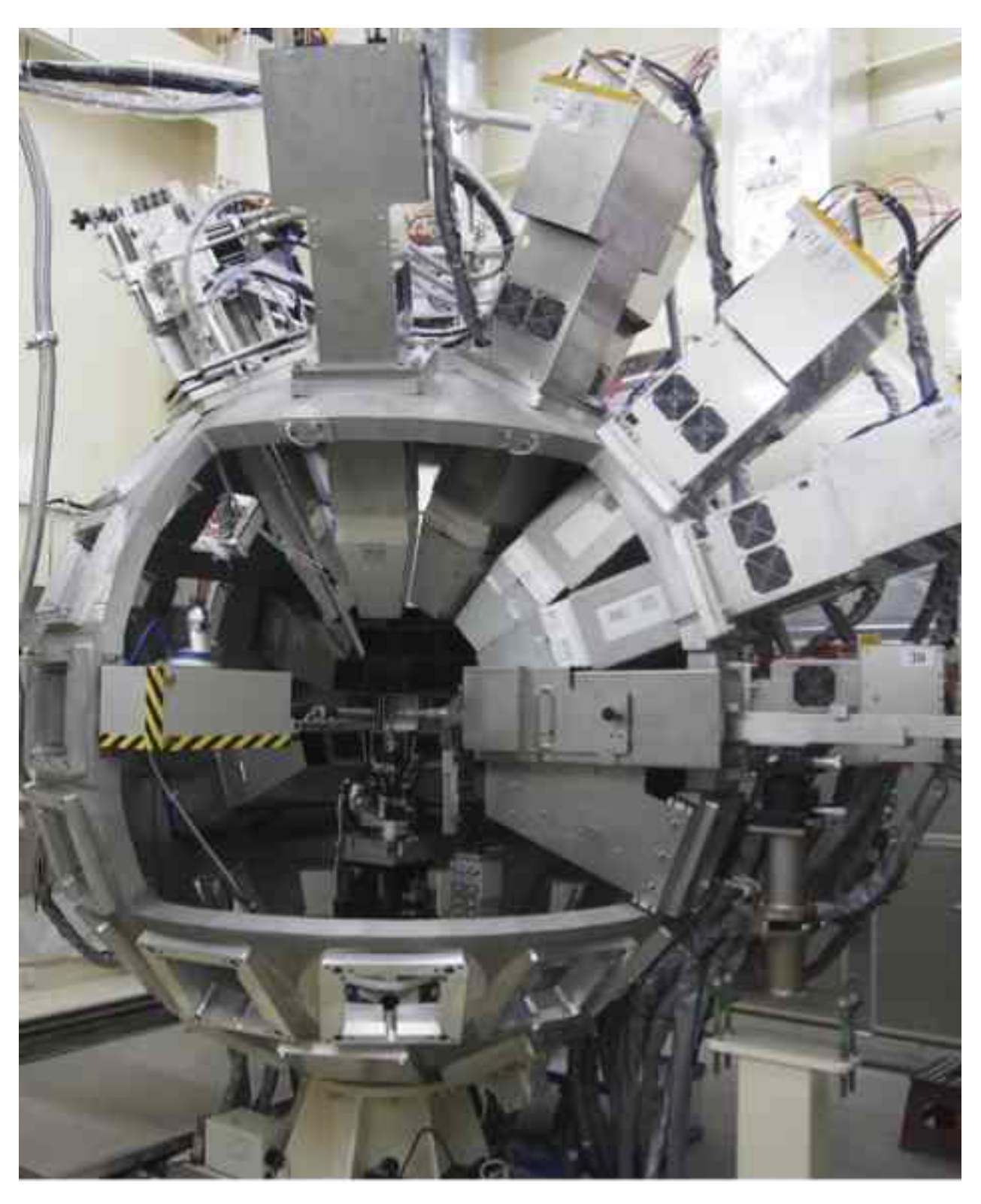
4SEASONS is a thermal neutron Fermi chopper spectrometer designed for measurements of dynamics in the 100–102 meV energy range [14,38]. A schematic view of 4SEASONS is presented in Figure 3a. Characteristic parameters of the spectrometer are listed in Table 2. It is installed at BL01 beam port for viewing the coupled moderator. Neutrons are transported to a sample position located 18 m downstream of the moderator through an elliptically converging straight neutron guide tube coated with supermirrors [39]. The incident neutrons are monochromated by a fast-rotating Fermi chopper positioned 1.7 m upstream of the sample position. In addition, the instrument has a T0 chopper for suppressing fast neutrons and two disk choppers for band definition. Neutrons scattered by a sample are detected over time by the one-dimensional (1D) 3He position-sensitive detectors (PSDs) placed at 2.5 m from the sample position. The angular coverage of the detectors relative to the direct beam ranges from −35° to +91° horizontally and from −25° to +27° vertically. The sample environment devices and detectors are enclosed in a large vacuum chamber without any window separating them, which minimizes background scattering and detector gaps (Figure 3b). To further reduce the background scattering from the sample environment, an oscillating radial collimator is available [40].
Compared to the other chopper spectrometers in MLF, 4SEASONS is designed to supply high thermal neutron flux by relaxing the resolution to observe weak inelastic signals [38]. Typical energy and momentum transfer resolutions under the elastic scattering condition are 6% relative to the incident energy and 1–2% relative to the incident wave number, respectively [14,41]. Another important feature of 4SEASONS is that it can perform measurements at multiple incident energies simultaneously (multi-Ei measurements) [4]. This was achieved by taking advantage of the fact that the Fermi chopper rotates considerably faster than the repetition rate of the neutron source, which is one of the simplest realizations of RRM [42,43]. The practical number of available incident energies is 3–4, which covers one or two orders of magnitude on the energy scale depending on experimental conditions.
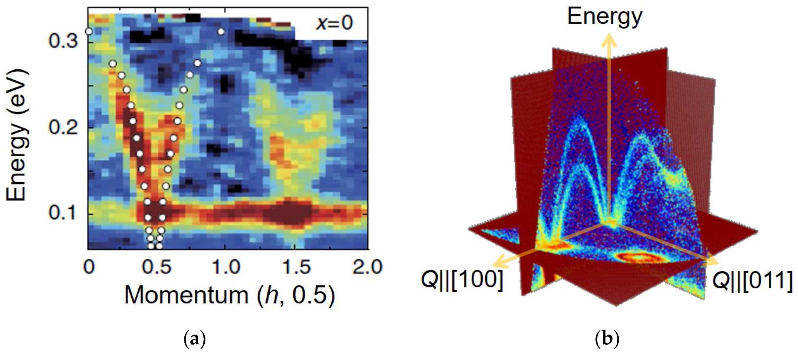
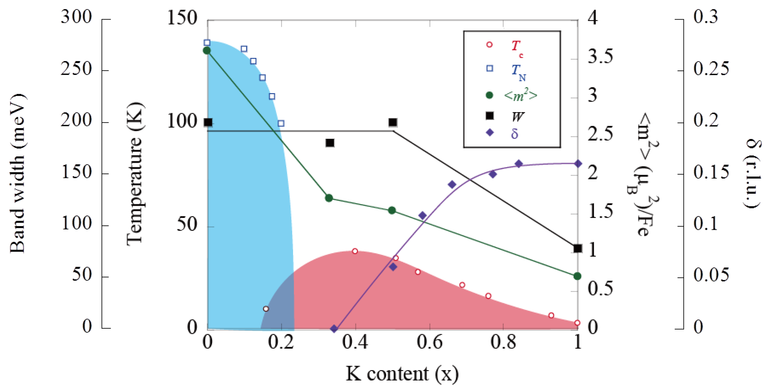
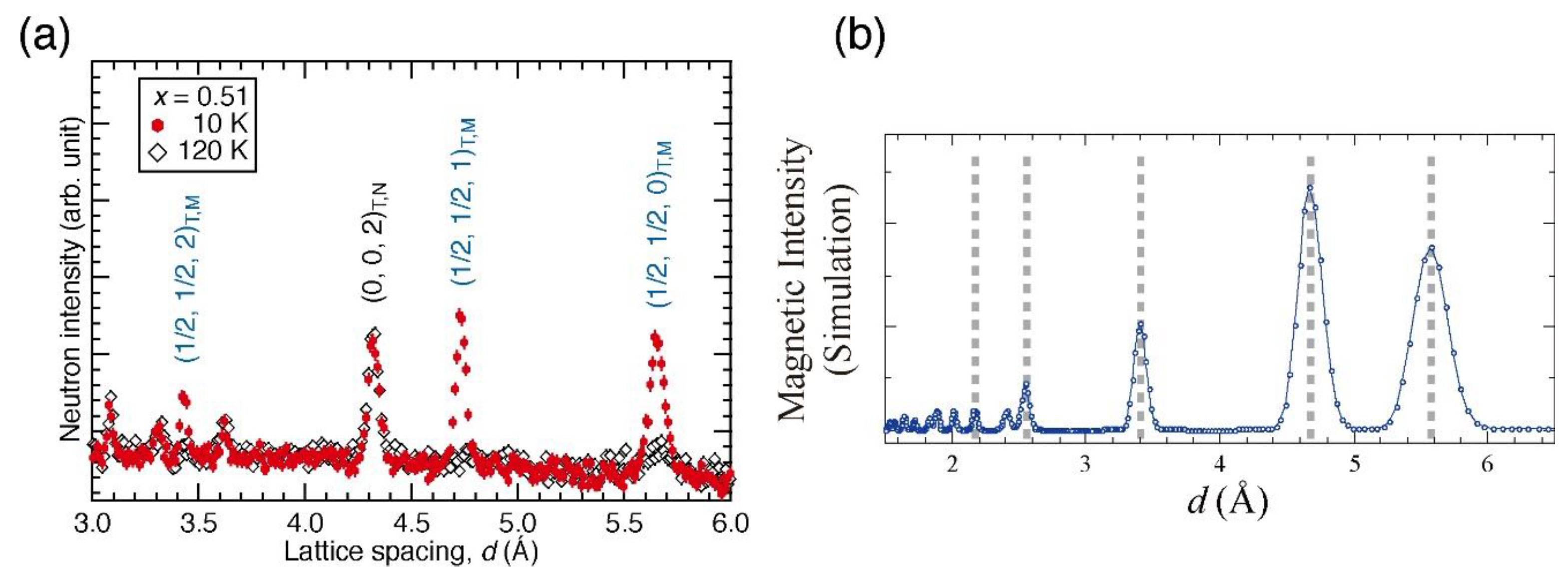
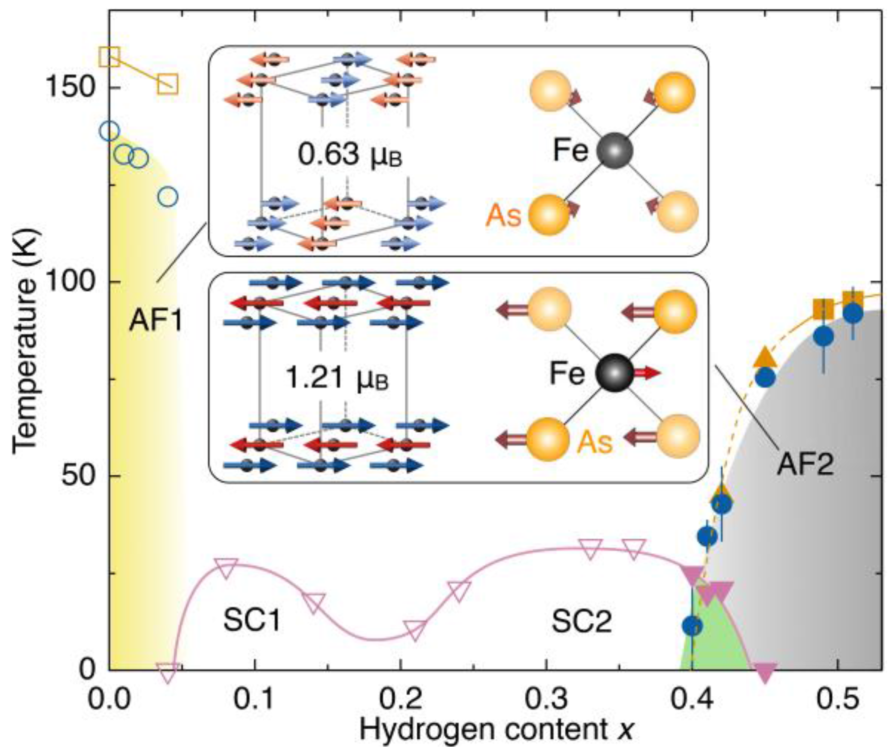
These features of the instrument were originally designed for studies of high-critical-temperature (high-Tc) oxide superconductors. Indeed, copper and iron-based superconductors are still major research targets at 4SEASONS [44,45,46,47,48,49]. Including these materials, strongly correlated electron systems and magnetism dominate 80% of the experimental proposals. Figure 4a shows one of the examples of 4SEASONS data, indicating the excitation spectrum of a single crystal of Pr1.40La0.60CuO4 [45]. Well-defined spin wave excitations emerging from h = 0.5 and 1.5 can be seen clearly up to ~300 meV. Another recent trend of experiments at 4SEASONS is four-dimensional (4D) mapping of the energy–momentum space in a single crystal by rotating the crystal. Figure 4b shows an example of the rotating-crystal measurement performed at 4SEASONS. It shows two-dimensional (2D) maps of the 4D phonon spectrum of copper as cuts on the (H, K, K), H-E, and K-E planes. Thanks to the high neutron flux, such a 4D spectrum can be obtained within a reasonable measurement time (1–3 days). This type of measurement is employed in more than 30% of experiments performed at 4SEASONS.

2.2. High Resolution Chopper Spectrometer, HRC

The High Resolution Chopper Spectrometer (HRC) offers high resolutions and delivers relatively high-energy neutrons for a wide range of studies on the dynamics of materials [13,15,16]: the range of incident neutron energies Ei = 5–2000 meV is available, and especially, by using Ei ≤ 300 meV, energy resolution of ΔE/Ei = 2% can be achieved in the best case. For conventional experiments, the energy resolution is set to ∆E/Ei = 3–10% to increase the neutron flux. A schematic layout of HRC is illustrated in Figure 5, and the characteristic parameters are listed in Table 3. On the primary flight path of 15 m, a supermirror guide, T0 chopper running up to 100 Hz at 9 m from the neutron source, Fermi chopper at 14 m from the source, and an incident beam collimator system just at the upper stream of the sample are installed. HRC has a detector array of 3He PSDs measuring 2.8 m in length and 19 mm in diameter at 4 m from the sample position, and it covers scattering angles from 3° to 62° for conventional experiments. Moreover, another array of 3He PSDs measuring 0.8 m in length and 12.7 mm in diameter is installed at 5.2 m from the sample position, and it covers scattering angles down to 0.6°. The incident beam collimator system having two collimators composed of slits of vertical sheets of Cd is installed for reducing background noise and one of the two collimators is selected: coarse collimation of 1.5° for conventional experiments using detectors down to 3° and fine collimation of 0.3° for low-angle experiments using detectors down to 0.6°.
At HRC, three types of inelastic neutron scattering experiments can be performed: high-resolution experiments in the conventional energy-momentum space, eV neutron spectroscopy, and neutron Brillouin scattering (NBS). In high-resolution experiments in the conventional space, the dynamical structure factor in a spin system can be determined in the full energy-momentum space, and many studies on condensed matter physics can be performed, for instance [50]. The dynamical structure factors of the multiferroic system NdFe3(BO3)4, layered nickelate R2−xSrxNiO4 (R = La and Nd), and carrier-doped Haldane system Nd2−xCaxBaNiO5 were determined over the entire Brillouin zone. As a result, microscopic interactions in these systems could be discussed. In eV neutron spectroscopy, intermultiplet transitions in a skutterudite compound SmFe4P12 with natural Sm were observed successfully by using Ei = 0.5 eV, where the absorption cross-section of natural Sm is the minimum. We have started observing high-energy magnetic excitations in metallic antiferromagnets such as Cr. When the full power beam is available, we expect to observe electronic excitations [51].
Owing to the kinematic constraints of neutron spectroscopy, to observe NBS, that is, inelastic neutron scattering close to the forward direction, an incident neutron energy in the sub-eV region with high resolution is necessary, and the scattered neutrons need to be detected at very low scattering angles. At HRC, NBS experiments became feasible by reducing the background noise at low angles down to 0.6°. The principle of NBS is not new [52,53,54], and the energy–momentum space accessible by using NBS has been extended utilizing higher-energy neutrons in spectrometers such as BRISP at the Institut Laue-Langevin (ILL, Grenoble, France) [55].
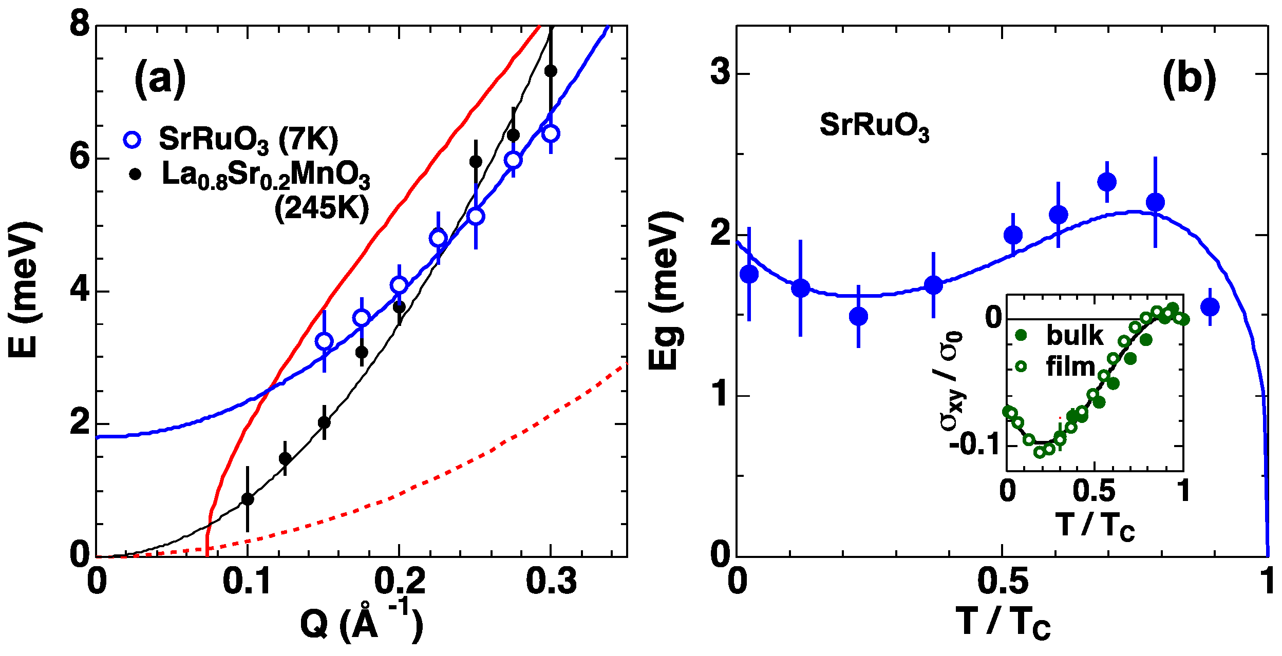
To show the feasibility of NBS at HRC, observation of spin waves was demonstrated using a polycrystalline sample of a well-known cubic perovskite ferromagnet, La0.8Sr0.2MnO3: the observed spin wave dispersion relation agreed well with the previous single-crystal result [13]. For a similar cubic perovskite ferromagnet SrRuO3, we found a spin wave gap, as shown in Figure 6a [13]. SrRuO3 is a metallic ferromagnet with transition temperature TC = 165 K. Normally, cubic ferromagnets such as Fe, Ni, and La0.8Sr0.2MnO3 show very weak magnetic anisotropy, and therefore, the spin wave gap is negligibly small. However, SrRuO3 shows a finite spin wave gap. Moreover, SrRuO3 shows that anomalous Hall resistivity is not proportional to magnetization [56]. In SrRuO3, the band structure exhibits Weyl fermions (band crossings) owing to spin orbit interaction, which produces the Berry phase. The Berry curvature of the band crossing takes the functional form of the magnetic field of a monopole in the momentum space, and the fictitious magnetic field of the monopole is the origin of the anomalous Hall effect: the anomalous Hall conductivity σxy in SrRuO3 is well described by the Berry curvature of the Weyl fermion [56]. To detect the fictitious magnetic field in SrRuO3 with inelastic neutron scattering, we performed NBS experiments [57] because a large single crystal necessary for inelastic neutron scattering had not been synthesized until very recently. Well-defined spin wave peaks were observed, and the dispersion curve was well fitted to E(Q) = DQ2 + Eg at temperatures (T) below TC. The spin wave gap Eg showed non-monotonous T dependence and was well explained by the theoretical function Eg(T) = aM(T)/[1 + bM(Txy(T)] with adjustable parameters a and b, where M(T) is spontaneous magnetization, as shown in Figure 6b. As mentioned above, σxy is described by the Berry curvature, and therefore, we showed for the first time that inelastic neutron scattering detects the Berry phase or the fictitious magnetic field of monopoles through σxy. Until this study, Weyl fermions were discussed in transport phenomena only, in terms of spintronics. We showed that the Berry curvature is an observable of inelastic neutron scattering and that the spin dynamics directly reflects Weyl fermions. This result has revealed a novel connection between the transport and the dynamical magnetic properties through the enhanced spin-orbit coupling effect.
At HRC, many high-resolution experimental studies in the conventional energy-momentum space and eV neutron spectroscopy studies have been performed or are in progress. We realized NBS experiments by using high-energy neutrons with high resolution by successful reduction of background noise at low angles. The NBS option makes HRC different from other inelastic neutron scattering instruments and opens up opportunities for contributing to current science by measuring collective excitations of non-single-crystal samples.

2.3. Cold-Neutron Disk-Chopper Spectrometer, AMATERAS

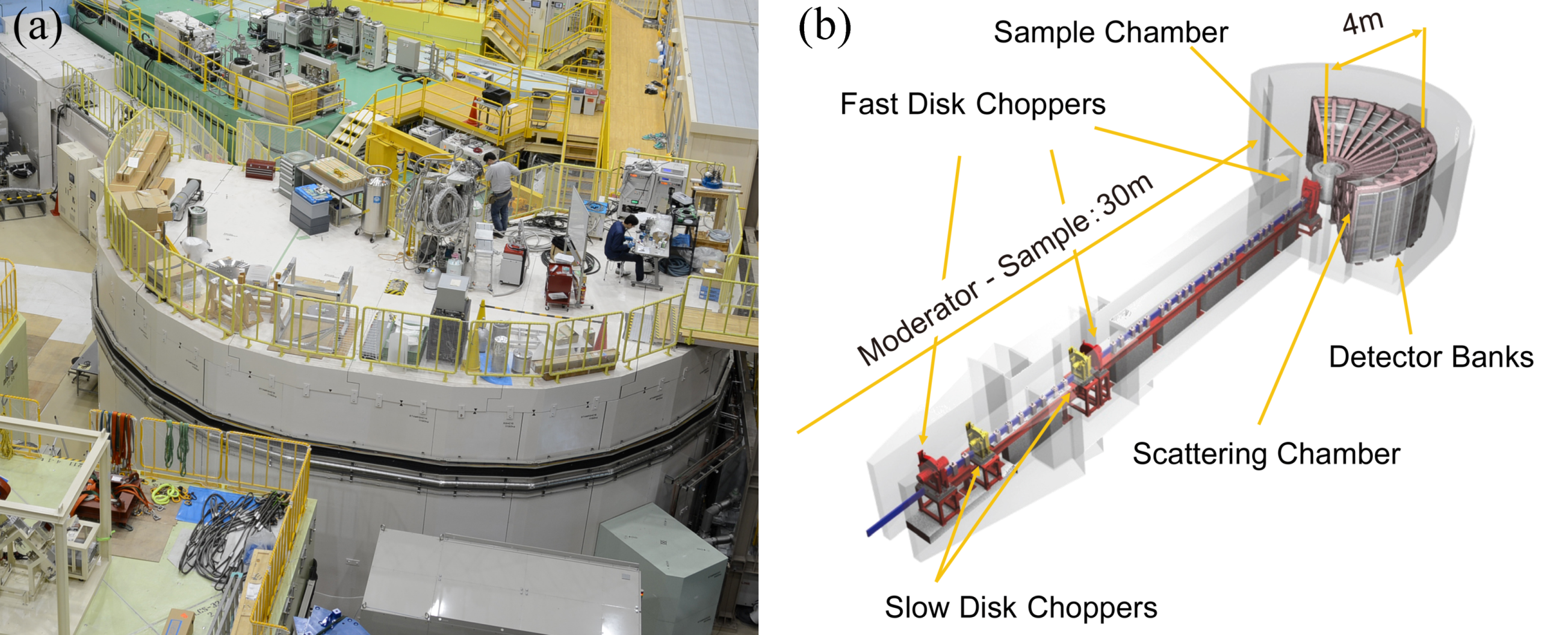
AMATERAS (Figure 7) is a multi disk-chopper spectrometer at BL14 [9,38,58]. The spectrometer is designed to carry out inelastic and quasielastic neutron scattering experiments on single crystal, powder, liquid and amorphous samples at neutron energies ranging from cold to sub-thermal. The most characteristic feature of AMATERAS is that the spectrometer employs the pulse-shaping technique, which has also been adapted to other modern cold-neutron chopper spectrometers at pulsed sources, namely, CNCS at SNS [10] and LET at ISIS [11]. One set of fast disk choppers located at the upstream position cuts out the ideal (sharp and symmetric) peak from the source pulse from a coupled moderator at MLF, which has a large intensity but broad and asymmetric pulse shape. By using a pulse-shaping technique and owing to the high peak intensity of the coupled moderator at MLF, AMATERAS realizes high-intensity, fine, and flexible energy resolution measurements [9]. AMATERAS has capability to carry out multi-Ei measurements by using RRM technique that was demonstrated for the first time at MLF [4].
The characteristic parameters of AMATERAS are listed in Table 4. The spectrometer uses the incident energy of 1–80 meV, while the best performance can be achieved at Ei ≤ 20 meV. The finest energy resolution is ΔE/Ei = 1% at Ei = 20 meV, and it becomes finer as the incident energy decreases. AMATERAS is equipped with newly developed fast disk choppers. The maximum possible revolution rate is 350 Hz, and the minimum burst time is 7.6 μs. Three sets of fast disk choppers are employed as a pulse shaping chopper (No. 1 in Table 4), a monochromator (No. 2 in Table 4), and a RRM frame overlap choppers (No. 3 in Table 4), and special care has been taken ensure that it works properly under multi-Ei measurement conditions [59]. These are located to satisfy the so-called RRM condition [60]. AMATERAS also has two sets of slow disk choppers that operate at 12.5 Hz or 25 Hz. These choppers have variable opening windows, which can be set from 0° to 175° and are used for frame over suppression and band definition. The detector bank can accommodate 448 3He 1D PSDs, 3 m in length (2.91 m in effective length), and covers a 0.67π scattering solid angle. We have installed 60% of the required number of detectors currently. The beam-transport of AMATERAS is designed to minimize background from fast neutrons and gamma rays from the source by utilizing curved guide geometry along the horizontal and to maximize the flux at the sample position by employing an elliptical-based geometry determined by series of studies on possible geometries [61,62,63]. Super mirrors with mirror indices m = 3.0 and 3.8 are mainly used. The AMATERAS shielding consists mainly of concrete and iron. Voids along the beamline are filled with concrete, iron, and polyethylene. The housing that accommodates the scattering chamber was constructed using precast concrete panels lined with 35-mm-thick B4C (25 wt %) mortar plates. Recently, we have started placing B4C plates on the floor under the scattering chamber because they can reduce the time-independent background.
On-beam commissioning of the spectrometer started in May 2009, and it was opened to users in December 2009. As mentioned previously, AMATERAS can cover many fields of investigation. Over its seven years of operation, more than 100 proposals have been carried out. Half of them are related to magnetism and strongly correlated electron systems. Studies on magnon–phonon coupled dynamics in multiferroic systems, spin dynamics in frustrated magnets and novel quantum spin systems, crystal field excitations and the underlying electronic properties have been carried out. A quarter of the studies at AMATERAS are related to the field of liquids, glasses, and other non-crystalline systems. Bosonic excitations, fluctuations related to super ion conducting, details of diffusive process in molecules in liquids are being studied. Studies on polymers and biomaterials are also being conducted using AMATERAS. Industrial applications, such as studies on the dynamics of atoms and molecules in rubber materials and on lattice dynamics in plating materials, are also being carried out. One should note that multi-Ei opportunity at this spectrometer has triggered attempts to perform novel data analysis, as described later, such as the mode-distribution analysis, which is a new approach to analyzing quasielastic neutron scattering data without any model assumptions [64].

2.4. Polarized Neutron Spectrometer, POLANO

POLANO is the younger generation of spectrometers operating at MLF [17,18,19]. As mentioned above, three direct geometry chopper spectrometers are now part of the user program. They cover rather wide energy and momentum spaces for the investigation of the dynamical structures on internal degrees of freedom of materials. POLANO was designed in a way similar to the other three instruments, except it can be used for polarization analysis. In light of recent discoveries in material science, many of the observed complex phenomena are largely caused by entangled physical degrees of freedom (spins, charges, orbitals, and even lattice vibration). A unique, effective, and direct way to observe these physical quantities separately is via polarization analysis.
POLANO is a collaborative project between KEK and Tohoku University under the aegis of KEK Inter-University Research Program, and it commenced in 2009. The construction of the instrument started in 2012, was almost complete in 2016, and radiological assessment for acceptance of the neutron beam was conducted successfully. Consequently, it was just approved as a proper neutron beamline, and its commissioning has just commenced.
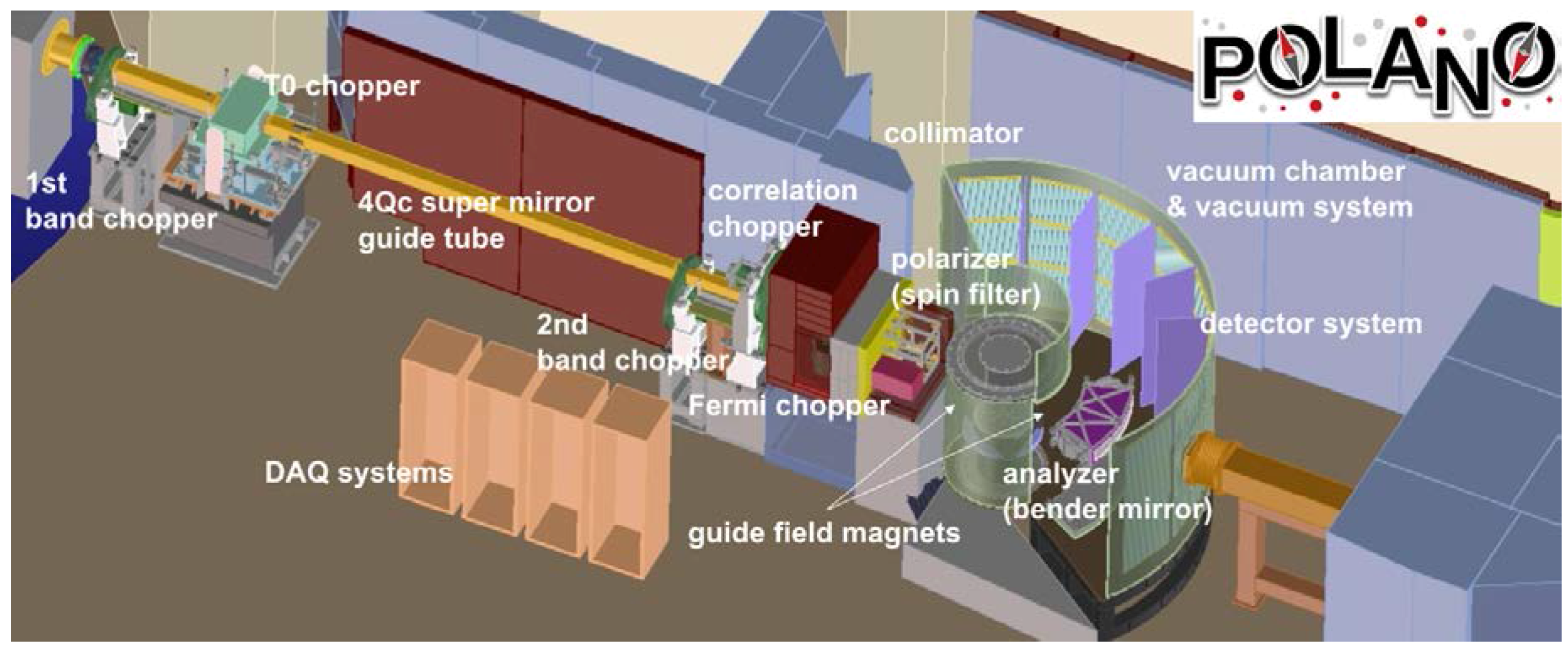
Our principal concept is to achieve polarization analysis of inelastic scattering at energies beyond the range of reactor-based neutron sources. A schematic view of the POLANO spectrometer is depicted in Figure 8, and its fundamental specifications are listed in Table 5. POLANO is located at BL23 in MLF, viewing the decoupled hydrogen moderator. The geometrical parameters of the spectrometer are as follows: distance from moderator to sample L1, distance from sample to detector L2, and distance from Fermi chopper to sample L3 are 17.5 m, 2.0 m and 1.85 m, respectively. To ensure the presence of additional space after the Fermi chopper, a rather long L3 was adopted, without losing much resolution. Energy resolution of ΔE/Ei = 3–5% and momentum resolution of ΔQ/ki = 1–2% were achieved. These values are sufficient for viewing most magnetic excitations and to observe the incommensurate structure in cuprate high-Tc superconductors, separately.
The pulse width of the decoupled moderator can be determined as Δtm = a/(Ei)1/2, where a = 2.5. After the moderator, the neutrons are transported by supermirror guide tubes with m = 4, optimized for neutron energy of 110–120 meV. An elliptical guide, which is optimized section-wise (section length = 50 cm), can yield a neutron flux of 3.9 × 10⁵ neutrons/(s·meV·cm2·MW), which is almost comparable to the coupled moderator beamline at E ~ 100 meV. The focusing guide tubes affect beam divergence, and therefore, beam profile can be estimated. An SEOP 3He filter cell will be placed at L = 16.4 m from the moderator. The 3He filter has a beam width of 8 cm at the bottom and 4 cm at half height. In the early stages, 3He cells with a diameter of 5 cm will be used for neutron spin polarization. A bending mirror with m = 5.5 can be used as the spin analyzer placed after sample position in a large vacuum chamber. Relatively high energies of up to 42 meV can be made available for polarization analysis. The vacuum chamber is composed of three sections and is designed to be detachable. The first chamber is the sample chamber, in which the sample is placed and the sample environments are set. The second is a connecting chamber that connects the sample chamber and the scattering chamber. Both the sample and the scattering chambers are sealed by thin (t = 1.5/2.0 mm) aluminum windows, and the chambers are completely isolated from air. Certain magnetic devices such as the spin flipper (positioned after the sample) will be installed in this section. The third is the scattering chamber, wherein the suite of analyzer mirror and detectors are placed. In addition, B4C vanes and liners are installed in the chamber.
In POLANO, we primarily target the research field of so-called strongly correlated electron systems, where both itinerant and localized electrons play an important role in recent diverse and complicated (interplay between spin, charge, orbital and lattice) science. As is well known, the neutron polarization analysis technique is essential to separately obtain contributing cross-sections. The generalized polarization cross-section can be written with initial and final polarization Pi, Pf as follows,
P f d 2 σ d Ω d E f = P i ( N * · N ) + ( P i · M * ) M + ( P i · M ) M * P i ( M * · M ) + i N ( P i × M * ) i N * ( P i × M ) + N M * + N * M i ( M * × M )
Here, N and M are the nuclear and the magnetic cross-sections, respectively. In the equation, the first term represents the nuclear cross-section, the following three terms are related to magnetic scattering, and the terms that follow represent nuclear magnetic interference and magnetic chirality. Thus, we can extract some part of the cross-section by measuring the combination of spin polarimetry up and down, namely, I++, I−−, I+−, and I−+.
We started spin polarization experiments up to Ef < 50 meV as the first step. Since the energy scale in heavy fermion or 4f electron systems is relatively low, it is one of themes carried out in the beginning. The search for direct evidence of orbital waves and multiferroic materials will also be the target to be explored. With the development of the wide-angle SEOP device, the energy range will be expanded to up to approximately 120 meV, entering a new paradigm for neutron polarization analysis. The reactor-based instruments no longer reach this high energy level, and the scheduled accelerator-based instruments are designed for lower energy range (cold neutrons). In this energy region, many phonon frequencies (Debye frequencies) are within this energy range in the case of solid state materials. Even high-Tc superconductivity will be objective. Hydrogen science can also be the target of research with neutron polarization analysis because the dynamical motion of hydrogen in most metal hydrides can be roughly described in the energy range of 70–150 meV energy as local vibrational modes.
We expect to realize neutron polarization at much higher energy as the final step. This needs revolutionary techniques to polarize sub-eV neutron spins, such as dynamical neutron polarization (DNP) or high polarization SEOP/MEOP. Once we obtain these high-energy neutron polarization techniques, research on itinerant electron systems and spin-charge separation in strongly correlated electron systems such as cuprates will progress remarkably.

2.5. Biomolecular Dynamics Spectrometer, DNA

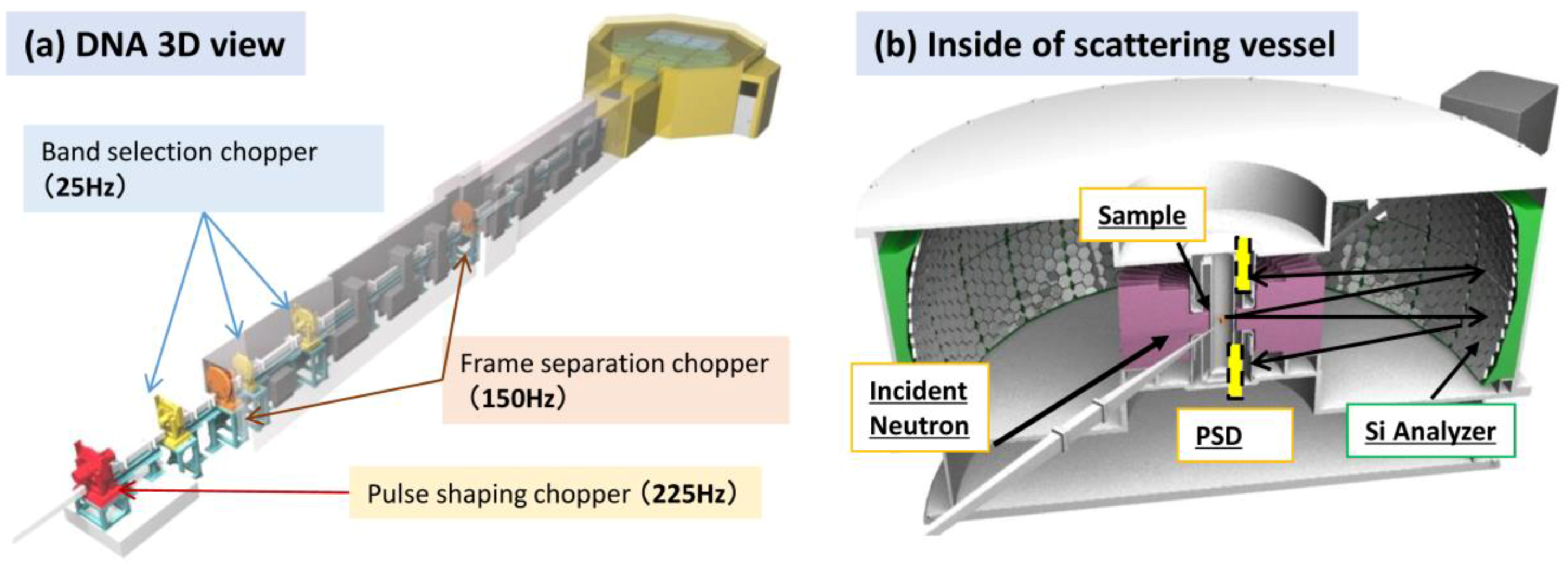
DNA, a time-of-flight (TOF) near-backscattering spectrometer (n-BSS), is a unique instrument among spallation pulsed neutron facilities over the world in terms of n-BSS equipped with a high-speed pulse-shaping disk-chopper [12]. Neutron beams from the coupled moderator, which provides the most intense but broadest pulse among all three moderators in MLF, is handled flexibly in terms of pulse width by this chopper, while maintaining its intensity and symmetry in the TOF spectrum. Si crystal analyzers back-coated with the neutron absorber reduce unfavorable background scattering of the instrument dramatically, achieving signal-to-noise ratios of ~105. Those factors are important for extending the application fields to dynamical behaviors of atoms and spins in bio-molecules, soft-materials, and strongly-correlated electron systems at the nanosecond timescale or in the micro-eV energy region.
Two visual representations (a three-dimensional (3D) view and an inside view of the scattering vessel) of DNA are shown in Figure 9a,b. The characteristic parameters are listed in Table 6. The Si-111 crystal analyzers, the first key device for DNA, installed in the vacuum vessel cover scattering angles ranging from −30° degrees to +150° in the horizontal plane and from +21° to −14° in the vertical plane (Figure 9b). The measurable momentum range is Q = 0.08–1.86 Å−1. The analyzer spherical surface is divided into the upper and the lower parts centered at different positions 102 mm upward and downward of the scattering center (sample position), respectively. Neutrons scattered by the sample are energy-analyzed under the near-back-scattering condition with Bragg angle θB ~ 87.5° and then countered by position-sensitive 3He gas detectors (PSDs) arranged on the circumference of the same scattering center and shifted upward and downward (Figure 9b). These arrangements of the analyzer units and the detectors allow us to angle-resolve scattered neutrons in the horizontal and the vertical directions two-dimensionally, and therefore, this spectrometer has the potential for use in experiments involving single crystalline samples.
The pulse-shaping chopper, the second key device in DNA, is located relatively upstream in the neutron guide at 7.75 m from the moderator because the time for slit opening at this position becomes the origin of TOF analysis. The chopper disk has four slits with two types of different slit sizes (3 with 30 mm slit and 1 with 10 mm slit), which allows us to adjust the energy resolution and rotational speed. The measurable energy resolutions are ΔE = 2.4 and 3.6 μeV with the 10-mm slit and the 30-mm slit, respectively. Another merit of the pulse-shaping chopper is that allows for the realization of a scanning method over a wide energy-transfer range while maintaining high energy resolution by changing the phase of slit opening relative to pulse trigger.
The DNA spectrometer is helping us to advance a plan to expand measurable momentum transfer Q range. For that purpose, 10 analyzer-mirror sets for determining the Bragg reflection of Si-311 were fabricated. Those ten Si-311 analyzer mirror sets will be installed in the vacuum vessel to cover scattering angles ranging from −30° to −150° by October 2018. The expected measurable momentum transfer range will be Q = 1.0–3.8 Å−1, and the expected energy resolution will be ΔE = 12 μeV with the 10-mm slit. With this advancement, measurements at high-Q with high energy resolution will become possible.
As another improvement plan, we are proceeding with the installation of three sets of diffraction detectors at a high scattering angle. Three sets of diffraction detector banks will be installed at scattering angles of around 2θ = +159°, +153°, and −159°, respectively, for the following purposes: to evaluate the energy distribution of an incident neutron beam from a measurement of a standard vanadium sample and to obtain the long-d diffraction pattern from powder samples with high resolution Δd/d < 0.5%. Such a diffraction measurement would also contribute to the evaluation of accuracy of inelastic scattering measurements.
Because of its expanded measurable energy range along with high energy resolution and low instrumental background, the DNA spectrometer is in a new category of back-scattering spectrometers with micro-eV energy resolution, different from conventional back-scattering spectrometers. Accordingly, the target sciences are expanded not only for quasi-elastic neutron scattering but also for inelastic neutron scattering with very high energy resolution. It is expected to increase the number of experimental proposals from the research field of strongly-correlated electron systems, such as low-energy excitation at low temperatures.

2.6. Village of Neutron Resonance Spin Echo Spectrometers, VIN ROSE

Two NSE spectrometers with resonance neutron spin flippers, that is, a NRSE instrument and a MIEZE instrument, have been installed by Kyoto University and KEK jointly at BL06 for viewing the coupled moderator. NSE is an essential spectroscopic technique, which has achieved the highest energy resolution with neutrons as the probe [65]. NSE with RSFs is a rather new approach [66]. In addition, the combination of NSE and a pulsed neutron source makes possible to scan a wide spatiotemporal space very efficiently. The beamline has been named VIN ROSE (VIllage of Neutron ResOnance Spin Echo spectrometers), and it will spawn many new field of spectroscopic methods [20]. Figure 10 shows a schematic top view of BL06. The main specifications of VIN ROSE are listed in Table 7.
NRSE is suitable for studying the slow dynamics of soft condensed matter with high energy resolution, while MIEZE offers the advantage of flexible sample environments, especially for magnetic field applications, at the sample position. The designed dynamic range of MIEZE is 0.2 < Q < 3.5 Å−1 and 0.001 < t < 2 ns, and that of NRSE is 0.02 < Q < 0.65 Å−1 and 0.1 < t < 100 ns, respectively. So far, the most successful application of NSE was to polymer systems, as reviewed in Ref. [67], and these systems are the target of NRSE. Owing to the abovementioned characteristics, MIEZE is expected to open new fields of study such as spin dynamics in strongly correlated systems [68,69,70].
The project was started in Japanese fiscal year (JFY) 2011, and the first neutron beam was accepted in JFY2014. After that, the performance of the installed neutron guides was tested using several methods. In the case of NRSE, the neutron flux observed at the guide-end position agreed well (95%) with the calculated value (6.9 × 10⁸ neutrons/(cm2·s) at 1MW). By contrast, the agreement was 56% for MIEZE (2.7 × 10⁸ neutrons/(cm2·s) at 1 MW) [71]. The first MIEZE signal was observed at the end of JFY2014. The combination of TOF and MIEZE (TOF-MIEZE) is a novel approach [72], and its detailed verification is in process. In the case of continuous neutron sources, the geometric restriction of MIEZE is very tight, that is, a very accurate setting for the distances among the source, flippers, and the detector is required. However, this requirement can be relaxed by using the TOF-MIEZE method, which was investigated both theoretically and experimentally by using BL06 [71]. Figure 11 shows the measured 200-kHz TOF-MIEZE signal and the corresponding power spectrum.
MIEZE will be open to user programs in the autumn of 2017. The program with NRSE will be delayed by a year.

3. Crystal Structure Group Instruments

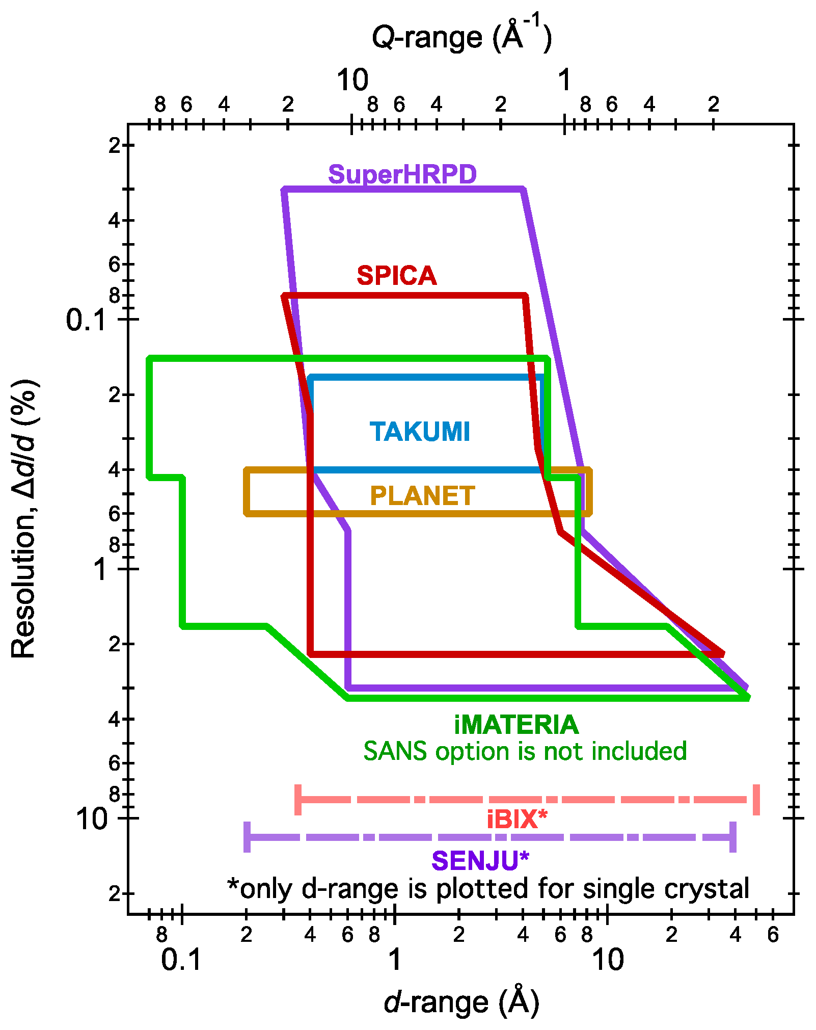
The MLF Crystal Structure Group consists of seven instruments for powder and single-crystal diffraction. SuperHRPD, SPICA, and iMATERIA are powder diffractometers with detectors having wide angular coverage. SuperHRPD has a very long flight path length to achieve its high resolution. SPICA adopts an elliptical neutron guide to achieve high incident flux. iMATERIA optimizes the flight path length and the neutron guide to cover a wide lattice spacing (d)-range along with high incident flux. PLANET and TAKUMI are diffractometers focusing on small gauge volumes for special purposes. PLANET has a relatively high incident flux and wide d-range for high-pressure studies, while TAKUMI has a relatively high resolution optimized for engineering studies. iBIX and SENJU are single-crystal diffractometers. iBIX is an atmospheric sample-space type instrument, while SENJU is a vacuum sample-space type instrument. Figure 12 shows the covering d-ranges and resolutions (Δd/d) covered by the diffractometers. The d-range of iMATERIA is the widest, and the Δd/d value of SuperHRPD is the smallest.
The notation of d is mainly used in this section because most of the instruments in this group deal with crystal analysis. For some instruments that also deal with liquid, amorphous and small angle scattering, the notations of both d and Q values are used.

3.1. Super High-Resolution Powder Diffractometer, SuperHRPD

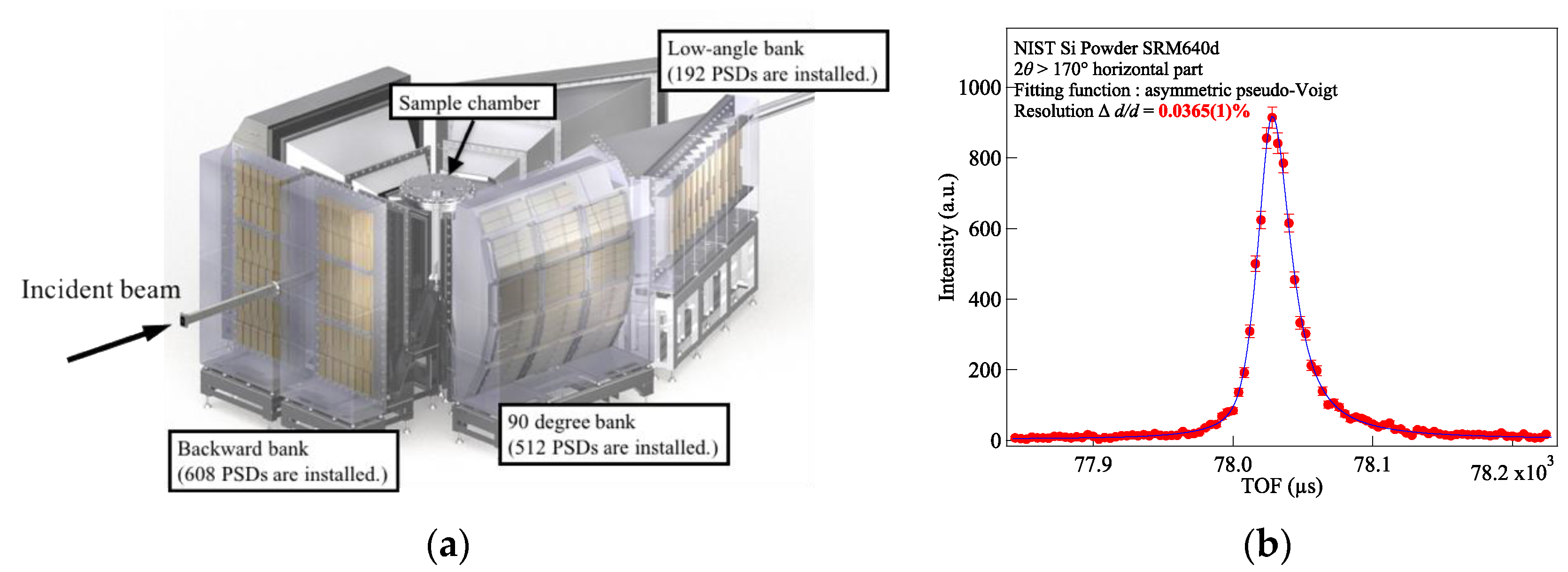
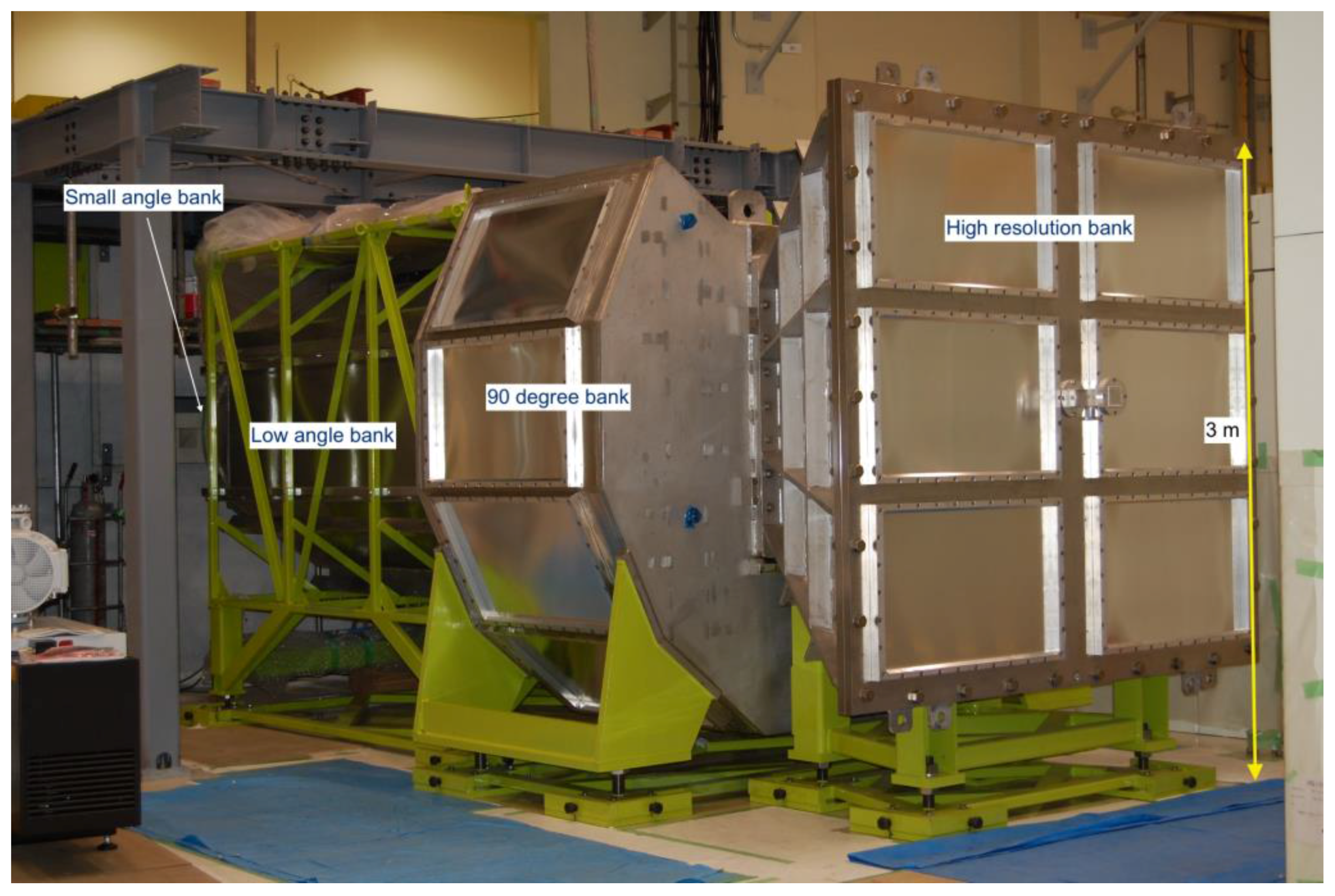
Super High-Resolution Powder Diffractometer, SuperHRPD [21], is located at about 100 m from the thin side of a decoupled poisoned moderator at MLF in J-PARC. SuperHRPD consists of a vacuum sample chamber with capacity of about 1 m3 and gas-filled scattering banks around it. To cover this large detector solid angle, about 1300 1D 3He PSDs have been installed in the backward bank, 90° scattering bank, and low-angle scattering bank (Figure 13a). Table 8 shows the instrumental specifications of SuperHRPD. SuperHRPD is expected to (1) detect tiny distortions never detected before in the field of strongly correlated systems, multiferroics, magnetic materials; (2) facilitate high-precision structural analysis of energy materials; (3) develop structure science of hybrid materials, supermolecules, and pharmaceuticals. Various achievements have been made in many fields by the user program and the instrumental group project that commenced in December 2008 [73,74,75,76,77,78,79,80].
The instruments are being improved continually, and a new detector system using PSDs measuring 8 mm in diameter was installed at all backward banks in 2014. The overall resolution of the standard powder sample improved from ∆d/d = 0.1% to 0.08% [81]. By using a limited detector area for the horizontal part corresponding to the highest scattering angle, ∆d/d of less than 0.04% was achieved. Figure 13b shows a peak-fitting result of this area obtained by using the asymmetric pseudo-Voigt function. Δd/d = 0.0365(1)% is obtained, which is equivalent to the value evaluated using a single crystal of silicon in June, 2008. This result shows the possibility of carrying out experiments with very high resolution when using a powder sample by using the limited detector area.

3.2. Special Environment Powder Diffractometer, SPICA

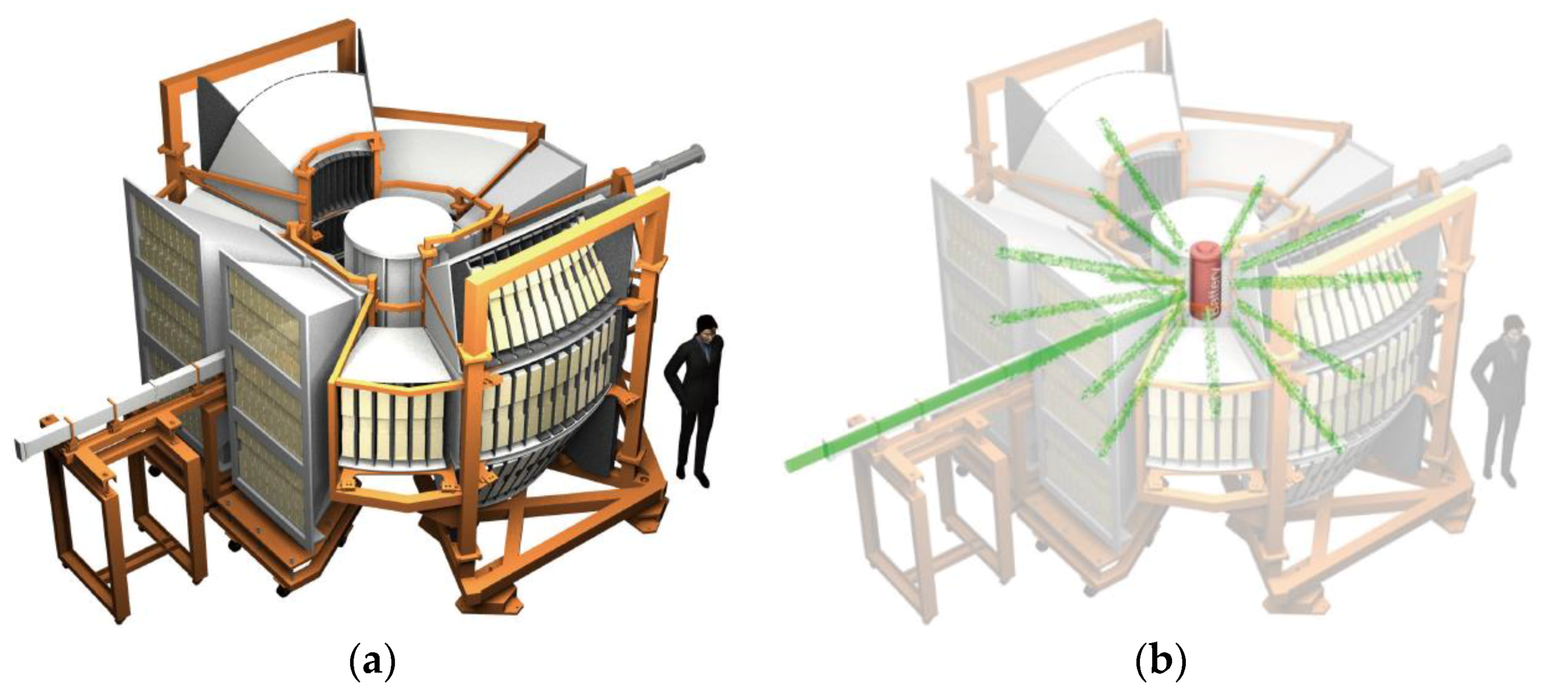
SPICA (Figure 14), a special environment powder neutron diffractometer, was built at BL09. This is the first instrument dedicated to the study of next-generation batteries, and it is optimized for operando measurement to clarify structural changes at the atomic level in the materials used in battery devices. To observe real-time structural changes in materials used in practical devices, a diffractometer with a good balance between intensity and resolution is needed. Therefore, SPICA was optimized to have the sample position of 52 m from the thin side of the decoupled poisoned moderator for achieving high resolution and to adopt an elliptical supermirror guide tube to enhance neutrons at the sample position. As a result, the highest ∆d/d of 0.08% is achieved at the back-scattering bank, and the neutron intensity increased to four times higher than that of the tapered-straight guide [22]. The specifications of SPICA are summarized in Table 9.
For real-time measurement of a practical device under an operative condition, SPICA provides space for samples with diameters as large as 2 m diameter, which makes it a very favorable sample-handling environment. Because the operando measurements are mostly carried out in air, coarse collimators with B4C-resin-coated aluminum blades are installed in the air-scattering chambers to reduce air scattering. In the previous simulation study, the loss of neutrons in the air-scattering chamber was approximately 6–11% over the wavelength range of 0.2–6.0 Å [82].
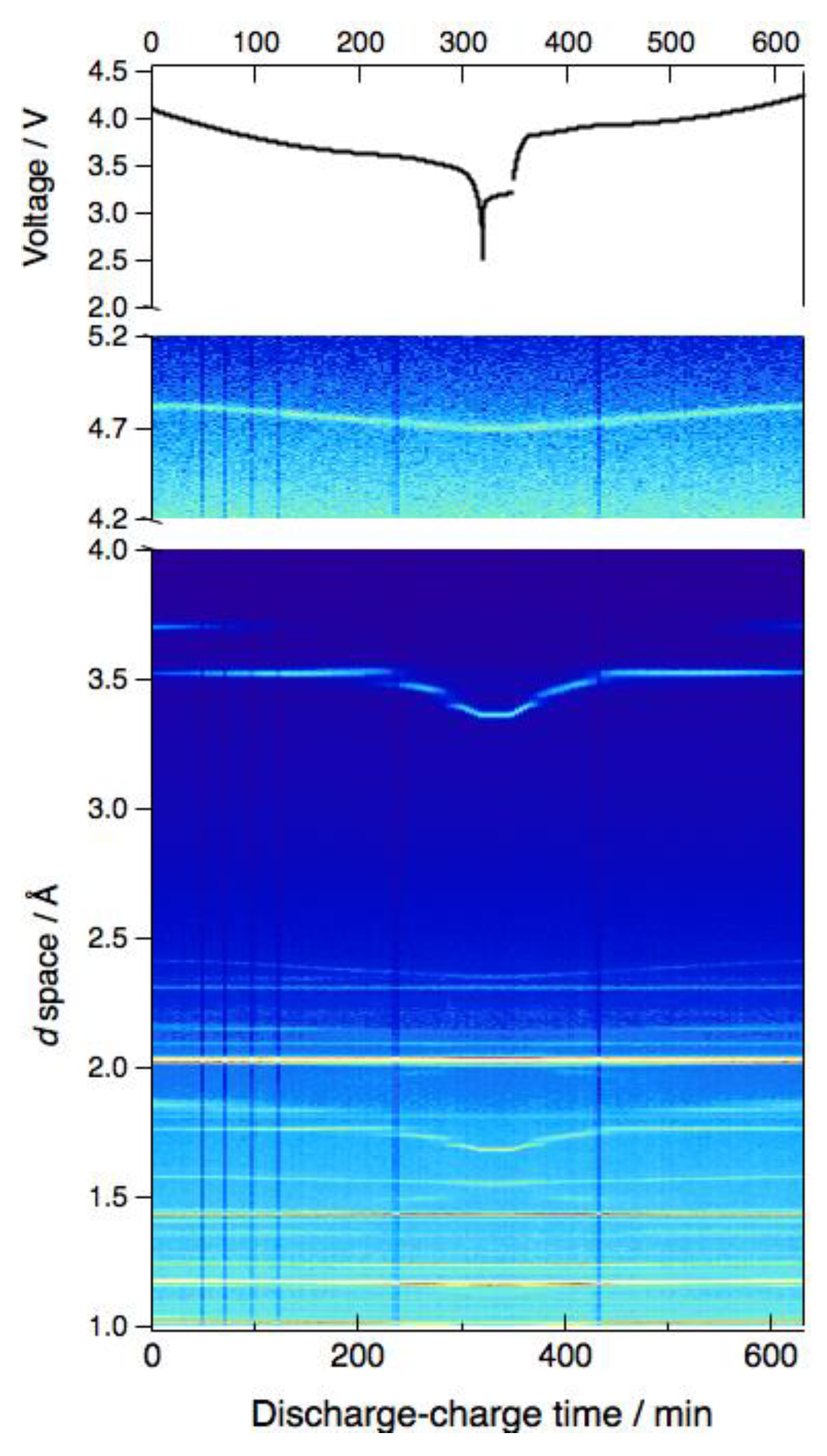
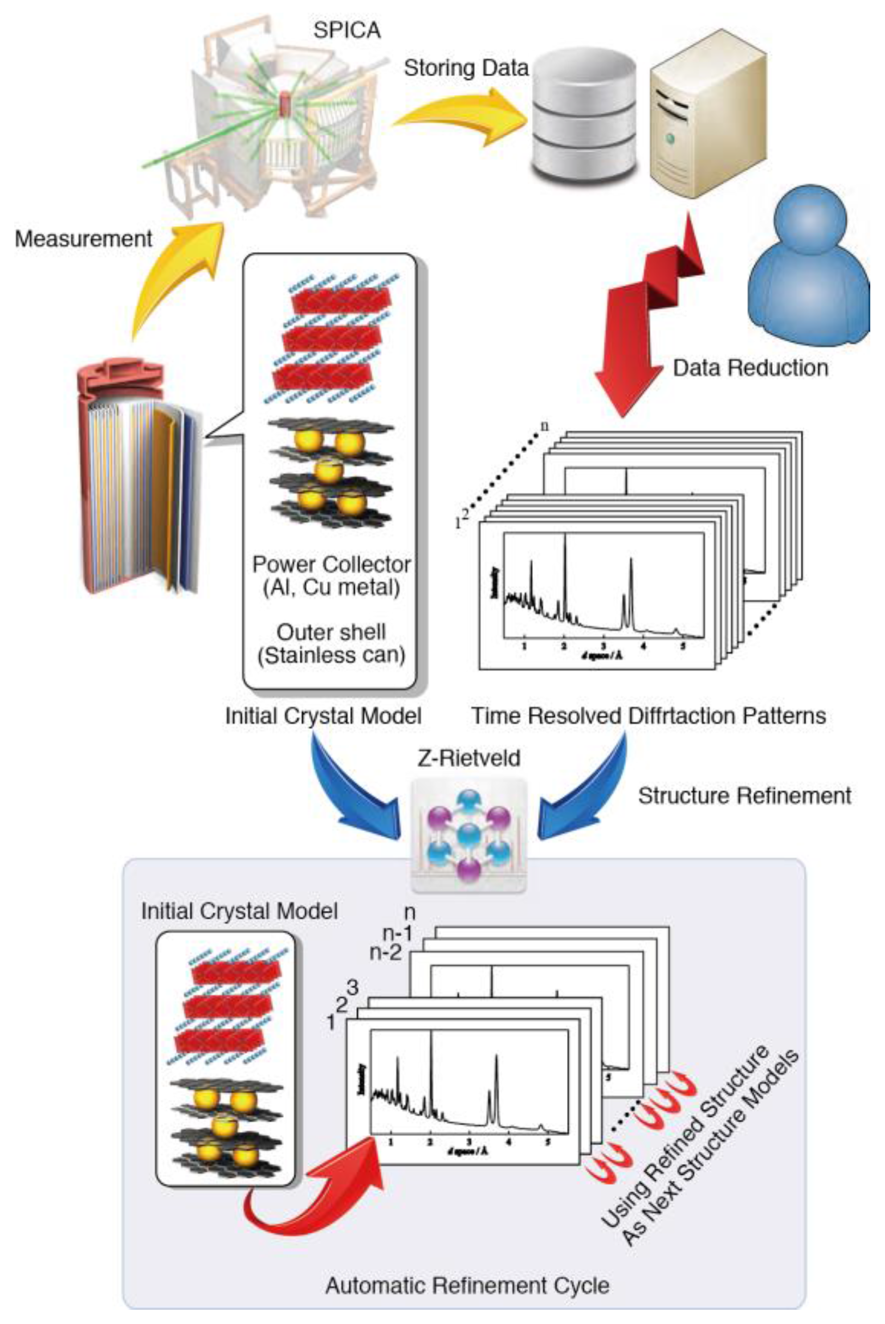
Figure 15 shows a typical operando measurement of a commercial Li-ion battery. Structural changes in the active materials, which depend on the lithium content, can be observed clearly. The lattice parameters of the anode and the cathode materials were extracted from the diffraction patterns as a function of the lithium content. An automatic data analysis procedure was developed, as shown schematically in Figure 16. Z-Rietveld, a Rietveld refinement software developed in J-PARC [83], can handle large numbers of diffraction data provided by the operando observation and refine the structures of both electrodes sequentially. The full-scale usage of SPICA has just begun. The first battery study on the structure dependence of the charge–discharge rate was published in 2016 [84]. SPICA will be used to carry out experiments on material science and observe structural changes in practical devices under an operative condition. Finally, it will be used to understand what happens in a device during its operation and for the development of next-generation batteries.

3.3. IBARAKI Materials Design Diffractometer (Versatile Neutron Diffractometer), iMATERIA

Ibaraki prefecture, where the J-PARC site is located, has decided to build a versatile neutron diffractometer (IBARAKI Materials Design Diffractometer (iMATERIA) (see Figure 17) [23]) to promote industrial applications by using the neutron beam in J-PARC. iMATERIA is planned to be a high-throughput diffractometer that could be used by materials engineers and scientists for their materials development work, like the chemical analytical instruments. The applications of neutron diffraction in materials science are as follows: (1) structural analyses of newly developed materials, (2) determination of the correlation between structures and properties (functions), and (3) determination of the relationship between structural changes and improvements of functions, especially for practical materials. To achieve those purposes, a diffractometer with super high resolution is not required. The balance among intermediate resolution around Δd/d = 0.15%, high intensity, and wide d coverage is more important.
This diffractometer is designed to look at a decoupled-poisoned supercritical hydrogen moderator (36 mm, off-centered) (BL20) and to have the incident flight path (L1) of 26.5 m with three wavelength selection disk-choppers and straight neutron guides having a total length of 14.0 m. The instrumental specifications are listed in Table 10. There are four detector banks, including a low-angle and small-angle scattering detector bank. The angular coverage of each detector bank is also shown in Table 10. When the rotation speeds of the disk-choppers are the same with a pulse repetition rate of 25 Hz (SF mode), the diffractometer covers 0.18 < d (Å) < 2.5 with Δd/d = 0.15% and covers 2.5 < d (Å) < 800 at three detector banks of 90°, low angle, and small angle with gradually changing resolution. When the speed of the wavelength selection disk-choppers is reduced to 12.5 Hz (DF mode), we can access a wider d-range, 0.18 < d (Å) < 5 with Δd/d = 0.15%, and 5 < d (Å) < 800 with gradually changing resolution with doubled measurement time from the SF mode. All four banks, including the small-angle bank, are user operational. It takes about 5 min (DF mode) to obtain Rietveld-quality data in the high-resolution bank with 500 kW of beam power for about 1 g of standard oxide samples. The automatic sample changer is the most important sample environment for high-throughput experiments. Our automatic sample changer [85] consists of sample storage, elevating system of two lines, two sets of pre-vacuum chambers, and a sample-sorting system. We can handle more than 600 samples continuously at room temperature without breaking the vacuum of the sample chamber.

3.4. High-Pressure Neutron Diffractometer, PLANET

PLANET is the beamline dedicated to high-pressure experiments [24]. By using various high-pressure devices, powder diffraction data can be obtained over wide pressure and temperature ranges of 0–20 GPa and 4–2000 K, respectively. The beamline is equipped with narrow incident slits and radial receiving collimators, which enable us to obtain very clean patterns without contamination of Bragg peaks by the materials surrounding the sample, such as a heater and a sample container. This contributes to precise structure determination of crystals and liquid/amorphous materials under high-PT conditions.
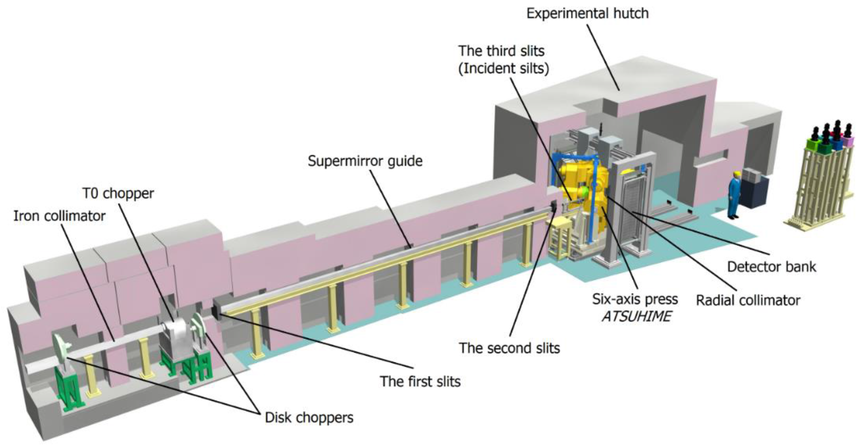
Figure 18 shows a cutaway view of the beamline. The characteristic parameters are listed in Table 11. The beamline is designed by adding the components specific to high-pressure experiments to a conventional powder diffractometer setup. Neutron beam originating from the moderator are truncated with an iron collimator spatially and choppers energetically, and useful neutrons are transferred to the experimental hatch by using a focusing mirror guide. They are truncated again by the second slits in front of the experimental hatch and are adjusted into smaller size than the sample by the third slits. The neutrons are introduced to the sample under high pressure and those diffracted toward 90° are detected using the 90° detector banks consisting of 320 PSDs. The detailed design and specifications are described in [24]. The high-pressure and high-temperature condition is generated using the six-axis multi-anvil press ATSUHIME designed for TOF measurements [86]. In this system, the sample is compressed isotropically using six anvils made of tungsten carbide. The mutual positions of the six anvils are controlled precisely to a precision of a few microns to ensure isotropic compression. The large sample space makes it possible to assemble a hydrogen source in the high-pressure cell, which can be used to study hydrides stable only under high-PT conditions [87]. The high-pressure and low-temperature condition is generated using the Mito system [88]. In this system, only the sample and the anvil parts are cooled by circulating liquid nitrogen around them, while the hydraulic oil is maintained at ambient temperature. Therefore, the sample pressure can be changed even at low temperatures. This system is applied to the study of ice under low-T and high-P conditions [89,90]. PLANET is widely used in the fields of geoscience, high-pressure physics, and material science.

3.5. Engineering Materials Diffractometer, TAKUMI

TAKUMI is a TOF neutron diffractometer dedicated to engineering material sciences. Careful analysis of the Bragg peaks in a neutron diffraction pattern can reveal important structural details of a sample material such as internal stresses, phase conditions, dislocations, and texture. Such information is often crucial in engineering applications, and the ability to carry out either ex-situ or in situ measurements makes neutron diffraction particularly useful in this respect. Detailed information about the design and performance of TAKUMI can be found in [25,26]. TAKUMI is installed at BL19 in MLF, and it has been designed to solve various problems related to engineering materials: (i) internal strain mapping in engineering components; (ii) microstructural evolutions during deformations and/or thermal processes of structural or functional materials; (iii) microstructural evolutions during thermo-mechanical processes of structural or functional materials; and (iv) crystallographic investigations of small regions in engineering materials. For those purposes, TAKUMI is composed of an incident beam slit with adjustable size and distance to the sample position, main detector banks positioned at the scattering angles of ±90°, several radial collimators of various sizes, and a large sample table that can be moved precisely. Figure 19 shows the appearance of TAKUMI.
TAKUMI covers engineering materials such as metals, ceramics, and composites varying in size from small to large. Its specifications are listed in Table 12. The total flight path is designed to cover a wide d-range simultaneously, which is very useful not only for stress mapping but also for various types of in situ observations. The d-range of about 0.25 nm is achieved without sacrificing the high intensity of MLF owing to operation at the same repetition rate as that of J-PARC (25 Hz). This d-range provides more than 15 peaks, including the lowest diffraction index one, for austenitic or ferritic steels. The minimum d and the maximum d can be tuned, or the d-range can be doubled for samples having larger lattice constants. The best peak resolution Δd/d is about 0.17%, which facilitates the separation of diffraction peaks from phases having similar crystal structures and to conduct peak broadening analyses, as well as to perform highly accurate strain measurements. Data reduction procedures have been developed to use the event data recording system maximally, as shown in Table 12, and this can be done during or after the experiment. Various types of sample environment devices have been developed and incorporated into TAKUMI, in addition to the common devices in MLF. Some of them were developed together with external users. They are open to all users for their experiments.
As one of the day-one instruments, TAKUMI has been open to the user program since 2009 and has assisted in the production of many publications, typically, papers related to strain mapping [91,92], in situ room-temperature loading [93,94], in situ low-temperature loading [95,96], in situ thermal treatment [97,98], and dislocation characterization [99].

3.6. IBARAKI Biological Crystal Diffractometer, iBIX

Single-crystal neutron diffraction is among the powerful methods to obtain the structural information, including hydrogen atoms. IBARAKI biological crystal diffractometer, iBIX (Figure 20), is a TOF neutron single-crystal diffractometer with high performance in elucidating the hydrogen, protonation, and hydration structures of mainly biological macromolecules in various life processes. To achieve high performance, we developed a new photon-counting 2D detector system using scintillator sheets and wavelength-shifting fiber arrays for the X/Y axes. Since the end of 2008, iBIX has been available to user experiments supported by Ibaraki University [27]. In JFY2012, we succeeded in upgrading the 14 existing detectors and installing 16 new detectors for the diffractometer of iBIX [28]. The total solid angle of the detectors subtended by a sample and the average detector efficiency increased by 2 and 3 times, respectively. The total measurement efficiency of the present diffractometer is one order of magnitude higher than that of the previous one, and the accelerator power has increased. At the end of 2012, it was possible to use iBIX regularly to investigate biological macromolecules in user experiments. The final specifications of the iBIX are given in Table 13. In 2015, the accelerator power of J-PARC reached 400–600 kW. The full data set of biological macromolecules for neutron structure analysis was obtained using iBIX as follows. The maximum unit cell size was set to 110 Å × 110 Å × 70 Å. The average sample volume was set to 2–3 mm3 and average measurement time to 7–10 days. If the accelerator power were to reach 1 MW, the total measurement time or the sample size will be reduced by half. To improve the quality of the integrated intensity of weak reflections, we developed a profile-fitting method for the peak integration of the data reduction software STARGazer [100]. The integrated intensities and model structure obtained using the profile-fitting method were more accurate than those obtained using the summation integration method, especially in the case of higher-resolution shells [101]. We have already prepared a user manual and a distribution package for the data reduction software, including the profile-fitting component.
In the future, the accelerator power of J-PARC will be improved to 1 MW. iBIX should be available regularly for full dataset measurement with a sample size of 1 mm3. We will continue to develop the data reduction software and beamline instruments to improve the accuracy of the intensity data obtained from small samples. Furthermore, we will validate whether full data measurement, reduction, and structure analysis of the sample are possible when using a large unit cell (132 Å × 132 Å × 132 Å) in iBIX.

3.7. Extreme Environment Single-crystal Neutron Diffractometer, SENJU

Single-crystal neutron diffraction is also a fundamental and powerful tool in materials science because of its availability to determine the arrangement of light elements and magnetic moments in crystalline materials with high accuracy and reliability. Thus, this technique has been an irreplaceable analytical tool for the development of new functional materials such as proton conductors, hydrogen-absorbing materials, and magnets. However, because a large (over 1.0 mm3 in volume) single-crystal sample is required, the number of experiments has been limited. Recently, we developed a new single-crystal neutron diffractometer called SENJU at MLF to alleviate this limitation.
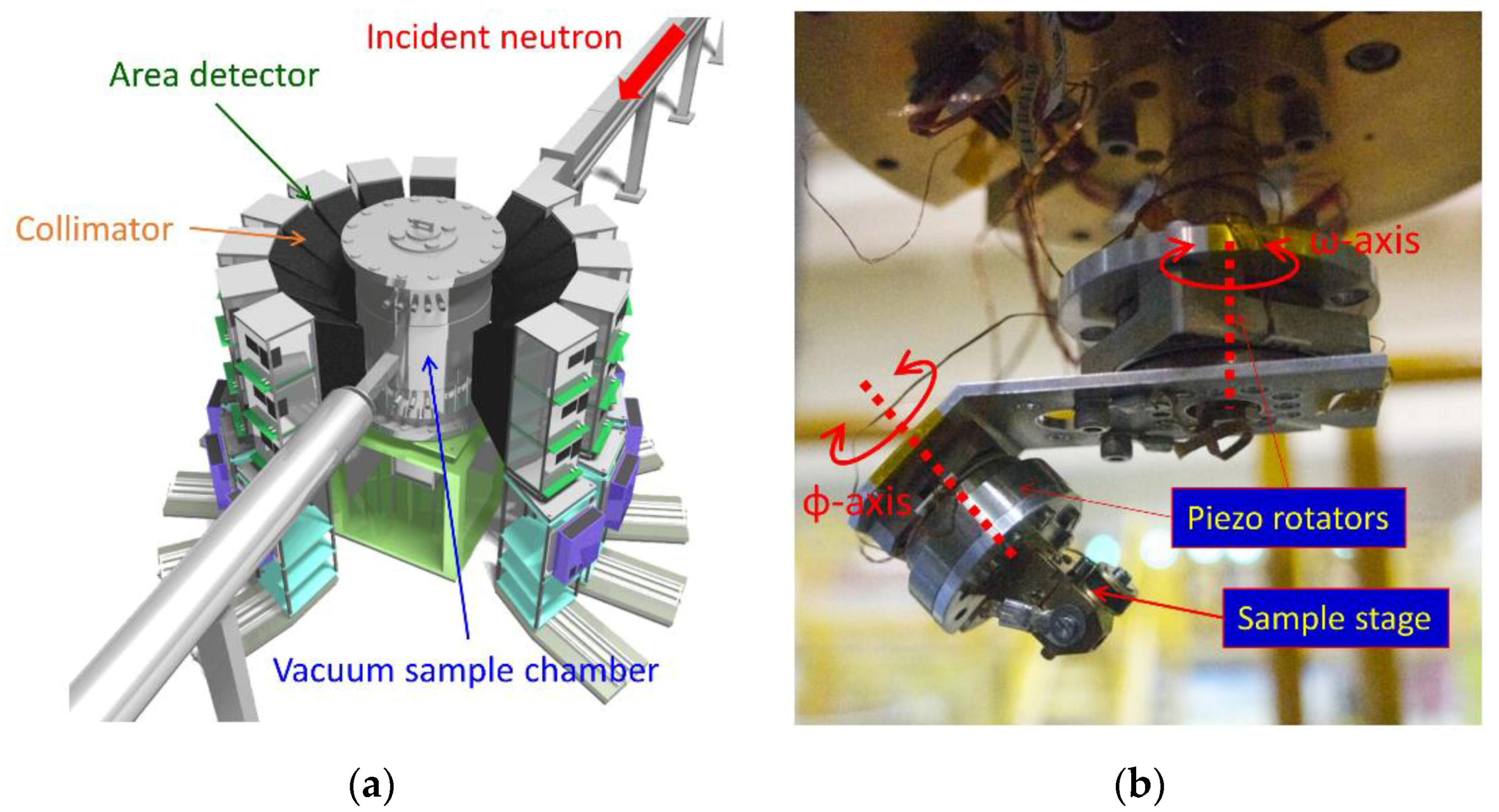
A schematic view of SENJU is shown in Figure 21a, and its characteristic parameters are listed in Table 14. SENJU has a vacuum sample chamber around which 37 area detectors are arranged cylindrically, as shown in Figure 21a. Owing to proper design of the chamber and collimators, a very low background was achieved; consequently, weak Bragg spots from the small sample crystal were observed clearly. In addition, large amounts of neutrons scattered from the sample were collected efficiently by covering a large solid angle with the area detectors. In addition to being used at the high-intensity neutron beam in J-PARC, these features have also allowed for diffraction measurements of 0.1-mm3-volume single crystals at SENJU [29]. At SENJU, a two-axis sample-rotation system for temperatures below 10 K was also developed using piezo-rotators that work under low-temperature and evacuated conditions, as shown in Figure 21b. In previous low-temperature devices, sample rotation has only been possible on one axis and, consequently, a few of the Bragg peaks required for structural analysis were immeasurable. Using the new sample-rotation system, almost all peaks required for structural analysis became measurable by SENJU, even at low temperatures [29]. The size of a sample crystal that can be measured using SENJU is compatible with that for measurements of various types of physical properties. This means that the development of SENJU has facilitated the determination of both crystal structure and physical properties with the same sample under the same condition. We believe that SENJU will open up a new frontier of material science using single-crystal neutron diffraction.

4. Nano-Structure Group Instruments

In the nano-structure group, four instruments are involved. These include a small- and wide-angle neutron scattering instrument TAIKAN (BL15), horizontal geometry reflectometer SOFIA (BL16), vertical geometry reflectometer SHARAKU (BL17), and total scattering diffractometer NOVA (BL21). These are not simply built based on existing instruments. TAIKAN has a large area detector bank to cover not only small scattering angle region but also larger angles, which can maximize the advantage of a pulsed neutron source. Moreover, TAIKAN is equipped with advanced neutron optics to fully utilize polarized neutrons for investigating magnetic structure in nano-materials. The ability to perform polarized neutron experiments is one of the key future requirements also at SHARAKU, because investigation of magnetic interface is an important task for this instrument. New approaches are being tried at NOVA and SOFIA. At SOFIA, an approach to measuring geometry by using a combination of a focusing supermirror and PSD is under development to increase the measurement efficiency. At NOVA, as one of attempts to solve the complex and long-standing problem of scan locus, a Fermi chopper has been installed.

4.1. Small- and Wide-angle Neutron Scattering Instrument, TAIKAN

The small-angle neutron scattering (SANS) technique has been indispensable in research on microstructures, higher-order structures, and hierarchical structures in materials science and life science. However, progress in nanotechnology and research on complex multi-component or multi-phase systems and nonequilibrium systems has created the need to endow the SANS instrument with the ability to measure structural information more efficiently with higher structural and temporal resolutions.
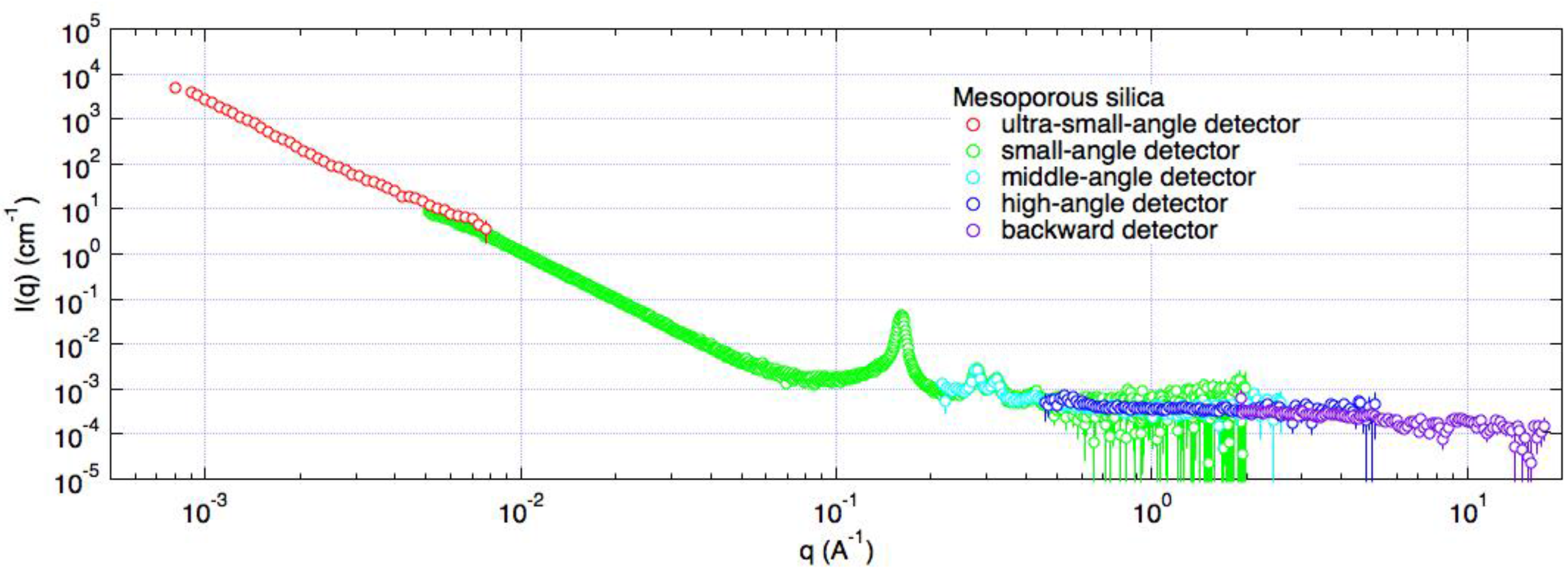
In order to meet these needs, the small- and wide-angle neutron scattering instrument, TAIKAN, has been developed and used at beamline BL15 in MLF within J-PARC since JFY2009 [30]. TAIKAN is designed to cover a wide Q-range (Q = 0.0005–20 Å−1) by using neutrons over a broad wavelength range (0.5–8 Å) produced at a coupled supercritical hydrogen moderator at the spallation neutron source in MLF, and its detector geometry covers a wide solid angle with the good connectivity of the scattering angle. TAIKAN is composed of the following set of components: a beam shutter, optical devices (neutron guide tubes, slits, collimators, multi-channel supermirror polarizer, and advanced magnetic beam focusing device), T0 chopper, three disk choppers, sample stage, vacuum scattering chamber, five detector banks, and beam stopper. On the small-angle and the middle-angle detector banks in the vacuum chamber, and the high-angle and the backward detector banks in atmosphere, more than 1500 3He PSD tubes with 8 mm in diameter and about 0.6 MPa in 3He gas pressure have been installed. On the ultra-small-angle detector bank in the vacuum chamber, a high-resolution scintillation detector with an active size of 127 mm in diameter and spatial resolution of about 0.5 mm has been installed. Figure 22 shows the scattering cross section of mesoporous silica obtained in the Q range of 0.0008–17 Å−1 by using TAIKAN. The Qmin value is extended down to 0.0005 Å−1 after combination with the beam-focusing device, which is a multiple multipole magnet system (quadrupole-spin flipper (SF)-sextupole-SF-sextupole-SF system) and can focus neutrons in the wavelength bandwidth of about 2.5 Å on the ultra-small-angle detector. Characteristic parameters of TAIKAN are listed in Table 15.
TAIKAN has been utilized by many users in various scientific fields, such as soft matter science, chemistry, biology, physics of magnetism, and steel science. To respond to their needs for efficient measurements under various sample conditions, a sample changer, a rheometer, tensile load cell, cryostats, electromagnets, and furnaces are available.

4.2. Soft Interface Analyzer, SOFIA

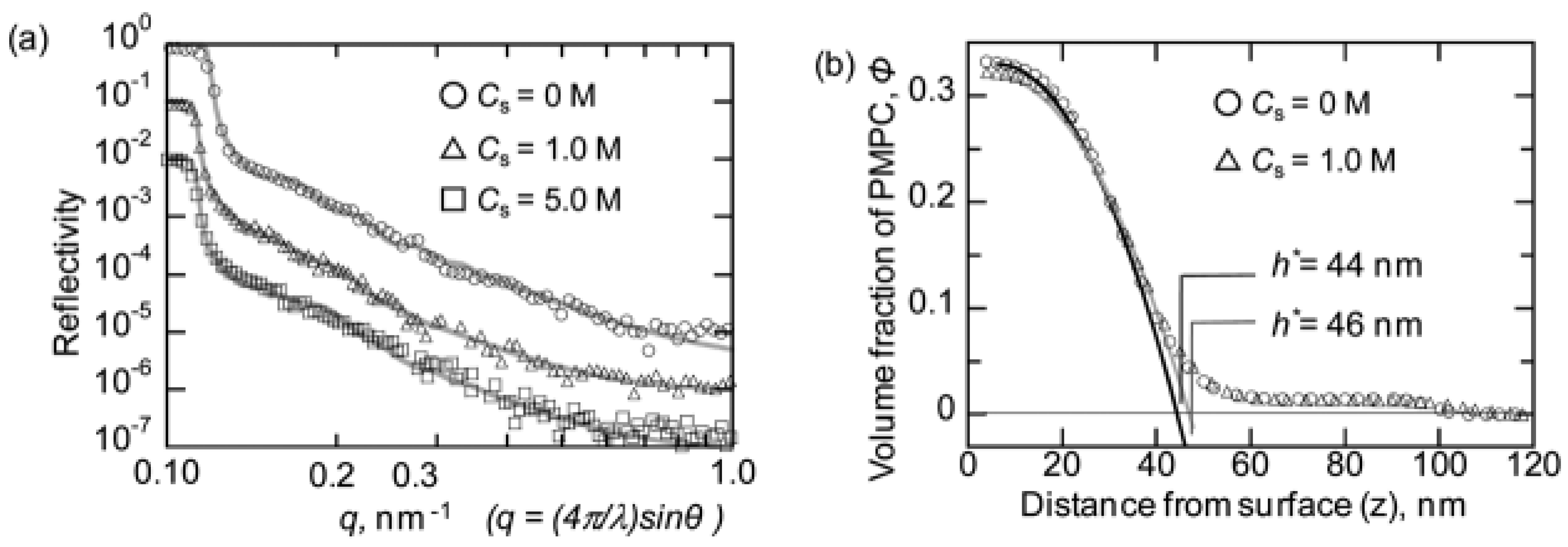
Neutron reflectometry is very useful for investigations of the structures of surfaces and buried interfaces composed of soft materials. Beamline 16 (BL16) of MLF is dedicated to a horizontal-type neutron reflectometer, in which free surface such as air–water interface can be measured using two downward neutron beams (2.22° and 5.71°). We started to accept the neutron beam onto the ARISA reflectometer relocated from the KENS neutron facility of KEK in 2008 tentatively, and replaced it with a brand-new reflectometer SOFIA (SOFt-Interface Analyzer) in 2011 through collaboration between JST/ERATO and KEK [31,32]. Owing to the high-flux beam of the J-PARC, the exposure time for one measurement is drastically shortened in comparison with that at various neutron facilities in Japan, such as the JRR-3 research reactor and the KENS spallation source. In addition, the accessible reflectivity is extended to 10−7 by careful background treatment, which is approximately two orders of magnitude lower than that of the reflectometers in JRR-3 and KENS.
Table 16 lists typical samples, sample size (and beam size), accessible Q range, and exposure time for full Q-range measurement at the SOFIA reflectometer with proton power of 500 kW. Table 17 lists the specifications of SOFIA. Even though the beam power is half of the planned value, 1 MW, the time required for one measurement is short and competitive with other state-of-the-art reflectometers owing to the high-flux beam of J-PARC. Hence, SOFIA is equipped with a sample changer capable of large quantities of samples, for example, 28 substrates with a diameter of 2-inch, for high throughput measurements. To take further advantage of the high-flux beam, SOFIA can change the repetition rate of the neutron pulses for use of a wide wavelength band from 0.2 nm to 1.76 nm by chopping every two neutron pulses, and it is equipped with sample environments for time-slicing measurement such as liquid injection system, temperature-jump system, and potentiometer [102,103]. These enable us to measure structural evolution over time slices of a few seconds to tens of minutes with a wide Q-range in the swelling process of polymer thin film, thermal diffusion by temperature annealing, electrochemical reactions in the charging/discharging process, and so on. As SOFIA employs an event-recording system similar to that in other instruments in MLF, the time resolution of kinetics measurement can be changed arbitrarily after the measurement considering the balance of data statistics and the speed of the structural change.
With these features, more than 60 reviewed papers and proceedings have been published using BL16 in various research fields such as polymer science, interfacial science, material science, electrochemistry, and tribology.

4.3. Polarized Neutron Reflectometer, SHARAKU

Neutron reflectometry has been used widely to investigate multi-layered structures and interfaces inside artificial thin films. Neutron reflectometry probes a nanometric-layered structure with the contrast of not only the nuclear scattering length density (SLD) but also the magnetic SLD. Therefore, neutron reflectometry allows for the analysis of magnetic structures in magnetic thin films [33]. The polarized neutron reflectometer SHARAKU was constructed at BL17 in MLF. SHARAKU uses polarized neutrons, which can enhance sensitivity to magnetic elements in thin films.
SHARAKU is equipped with a spin polarizer, spin analyzer, and two spin flippers inserted into the BL on demand because the spin polarization states of both the incident and the reflected neutrons must be determined for polarized neutron reflectivity measurement with full polarization analysis. The cold neutrons from the coupled moderator of MLF are passed through the polarizer, which consists of polarizing Fe/Si supermirrors, to polarize the neutron spin. The spin polarity can be switched using a non-adiabatic two-coil spin flipper with a flipping ratio of 40–80. The spin state of the neutrons reflected from the sample is analyzed using a set of stacked Fe/Si supermirrors for full polarization analysis measurements.
In the specular reflectivity profile measurement, a 3He gas tube detector is used. Both high sensitivity to neutrons and insensitivity to background noise of the 3He detector allows for neutron reflectometry measurements down to the reflectivity order of 10−6. SHARAKU enables us to use a 2D PSD and a multi-wire proportional neutron counter (MWPC) with a detection area of 128 mm × 128 mm, the pixel size of 0.5 mm × 0.5 mm, and spatial resolution of 1.8 mm. MWPC is used for off-specular neutron reflectivity and SANS measurements, including grazing-incidence SANS. The off-specular reflectivity measurements reveal not only the layered structure in the depth direction but also the lateral structure in the film plane of a sample. Table 18 summarizes the specifications of SHARAKU.
The sample is mounted vertically on a sample holder set on a rotating table with a diameter of 700 mm and a load capacity of 900 kgf; therefore, it has large flexibility for a variety of sample environment equipment. A 7T superconducting magnet and a 1T electromagnet can be used for the measurement of magnetic films. The magnetic field axis can be switched between the directions parallel and normal to the sample plane. A refrigerator system allows for neutron reflectometry measurement in the temperature range of 4–300 K. Sealed sample cells are equipped for measurement at the liquid-solid interface in a solution and measurements under controlled atmosphere.
The polarized neutron reflectometry experiment is a powerful method for the analysis of magnetic structure of artificial thin films; however, the research fields in the user experiment proposals are not limited to solid-state physics of magnetic materials. SHARAKU has accepted a wide variety of experiments, for instance, polymer thin films and electrochemistry.

4.4. High-Intensity Total Diffractometer, NOVA

Total scattering is a technique to analyze non-crystalline structure in materials by obtaining the real-space atomic-pair correlation function by Fourier transform of diffraction profile. NOVA was designed to perform total scattering, and it is the most intense powder diffractometer with reasonable resolution (∆d/d ~ 0.5%) in J-PARC. To realize high statistical accuracy in the high-Q range (Q = 2π/d, where d is a lattice constant), which has a sever effect on the reliability of the pair-correlation function, the neutron flight pass between the neutron source and the sample was shortened (15 m) and the wavelength bandwidth of incident neutrons was widened (~ 8 Å). Consequently, NOVA covers a wide Q range, 0.01 Å−1Q ≤ 100 Å−1, in one measurement. Based on the high neutron flux of J-PARC, real-time observation of non-equilibrium states is feasible. The construction of NOVA was supported by the New Energy and Industrial Technology Development Organization (NEDO) under Advanced Fundamental Research Project on Hydrogen Storage Materials (“HydroStar”) and is open to users since 2012. Characteristic parameters of NOVA are listed in Table 19.
One of the main objects of NOVA is to determine the mechanism of hydrogen storage in materials. To observe hydrogen absorption and desorption, NOVA is equipped with in situ sample environments such as H2/D2 gas atmosphere (up to 10 MPa, temperature can be controlled from 50 K to 473 K). The sample environments available in NOVA are listed in Table 20. Vanadium foil furnace (RT–1373 K) and impedance measurement apparatus (temperature: ≤ 550 K, freq.: 4 Hz–1 MHz) will be ready as soon as a radial collimator is installed. The cryogenic system of the common sample environment equipment in MLF is also expected to be ready as soon as the collimator is ready. Another unique feature of NOVA is its capability of inelastic measurement by using a Fermi chopper. A study is on-going for correction of the self-term cross section of 1H in S(Q) by measuring S(Q, E).
A variety of scientific fields have been covered by NOVA: hydrogen storage materials (for example [104,105]), battery materials containing amorphous and liquid phases (for example [106,107]), and magnetic structure analysis (for example [108]). The capability of longer d-range measurement is useful for magnetic structure analysis.

5. Pulsed Neutron Application Group Instruments

The pulsed neutron application group consists of four unique instruments in various objects other than neutron scattering. ANNRI developed a unique γ-ray spectroscopy method combined with a TOF method. The challenge associated with NOP is the determination of neutron lifetime with an accuracy of 1 s, which will be a great step up from the standard model for elementary particle physics. NOBORU provides opportunities for R&D activities and trial users who have new ideas. RADEN disseminates the power of energy-resolved neutron imaging to the world. The outline of each instrument is described in the following section. ANNRI and NOBORU constitute the JAEA beamlines, NOP is the KEK beamline, and RADEN is the public beamline. ANNRI, NOBORU, and NOP have been open to the user program since 2008, whereas RADEN joined the program in 2015.

5.1. Accurate Neutron-Nucleus Reaction measurement Instrument, ANNRI

Accurate Neutron-Nucleus Reaction measurement Instrument (ANNRI) is used for studies of nuclear science, such as nuclear data for nuclear technology and astrophysics, quantitative analyses, and so on [34].

5.1.1. Instrument Description

In ANNRI, a neutron collimator, neutron filters, and chopper systems are installed to deliver an intense neutron beam with good quality to detector systems. Two detector systems are installed. An array of germanium (Ge) detectors is installed at the flight length of 21.5 m. The other one is a NaI spectrometer located at a flight length of 27.9 m. Using the neutron TOF method and the γ-ray detector systems, both the energy of incident neutrons and the energy of prompt γ-rays from a reaction are obtained.
The array of Ge detectors is composed of two cluster-Ge detectors, eight coaxial-Ge detectors, and anti-Compton shields around each Ge detector. Because each cluster-Ge detector has seven Ge crystals, the array has 22 Ge crystals. The peak efficiency of the spectrometer is 3.6 ± 0.11% for 1.33-MeV rays [109]. The NaI(Tl) spectrometer is composed of two anti-Compton NaI(Tl) scintillators with neutron and γ-ray shields. The cylindrical NaI(Tl) scintillators are located at 90° and 125° with respect to the neutron-beamline, respectively.

5.1.2. Applications

ANNRI is used for neutron-capture gamma-ray measurements in nuclear engineering, elemental analysis and nuclear astrophysics.

5.1.3. Specifications

The typical specifications of the instruments in ANNRI are given in Table 21.

5.1.4. Highlights

  • A novel analytical technique that combines prompt gamma-ray analysis with the TOF technique (TOF-PGA) was developed [110].
  • In the neutron-capture cross section measurements of minor actinides, analyses of 244Cm, 246Cm, 241Am, and 237Np have been completed. The results for 244Cm and 246Cm show that neutron-capture cross sections are deduced by using ANNRI, where a small amount (less than 1 mg) of a high radioactive sample can be used [111,112,113].
  • In the neutron-capture cross section measurements of stable isotopes, miss-assigned resonances were found for 112Sn, 118Sn, 107Pd, and 142Nd. These results show that even in the case of a stable isotope, there are many miss-assigned resonances in the evaluated values [114,115,116].

5.2. Neutron Optics and Fundamental Physics, NOP

Neutron Optics and Physics (NOP) is a beamline for studies of fundamental physics namely: elementary particle, nuclear, and quantum physics.

5.2.1. Instrument Description

The beamline is divided at its upstream into three branches to conduct different experiments in parallel [117]. Each branch can be used to perform several types of physical experiments in parallel. The three branches are follows: Polarized beam branch, which produces polarizing neutrons by using magnetic supermirrors in its bender; Unpolarized beam branch, which produces the highest energy and the most intense neutron flux in these branches with a supermirror bender; and Low-divergence beam branch, which produces small divergence but dense neutron beam.

5.2.2. Applications

Physics experiments using slow neutrons are being carried out. Precise measurement of the neutron lifetime is performed at the polarized beam branch. Pulsed ultracold neutrons (UCNs) by a Doppler shifter are available at Unpolarized beam branch. Low-divergence beam branch is used for testing detectors and optical elements.

5.2.3. Specifications

The typical specifications of the instruments used in NOP are given in Table 22.

5.2.4. Highlights

Ultracold neutrons (UCNs), which have energy less than ~250 neV (velocity of 6.8 m/s), are used for various precision measurements in fundamental physics. A Doppler shifter produces pulsed UCNs at the NOP beamline [118]. It reflects very cold neutrons (VCNs) with velocity of ~136 m/s by using a mirror moving at 68 m/s and produces neutrons with velocities less than 20 m/s. The intensity of UCNs is 160 cps at 1 MW.

5.3. NeutrOn Beam-line for Observation and Research Use, NOBORU

This instrument serves a versatile neutron field for characterizing the neutron source as well as for R&D on various devices, irradiation and analysis of materials, and so on.

5.3.1. Instrument Description

NOBORU was constructed at BL10 in MLF at J-PARC in 2007 by the neutron source group [36]. The primary mission of NOBORU is facility diagnostics to study neutronics performance of the neutron source at MLF [119]. In addition, NOBORU provides a suitable neutron environment for testing various detectors and devices, new ideas for experimental techniques, and irradiation of high-energy (~MeV) neutrons. The instrument has a beam cross-section of 100 mm × 100 mm at a sample position of around 14 m from the neutron source. Figure 23 shows the instrument components of NOBORU.

5.3.2. Applications

NOBORU serves as a test beam port to encourage the introduction of innovative instruments into MLF. The key devices installed in instruments of MLF, such as MAGIC chopper [120], wavelength-shifting fiber scintillator detector [121,122,123], and SEOP system, were developed using NOBORU. The innovative pulsed-neutron imaging instrument, RADEN at BL-22, also uses R&D experiences of the imaging experiment conducted using NOBORU [124,125,126,127,128,129]. Recent development of white neutron holography enables us to observe the 3D local structure of boron-doped materials.

5.3.3. Specifications

The typical specifications of the instruments used in NOBORU are given in Table 23.

5.3.4. Highlights

  • Studies on the high-field magnetic structure of BiFeO3 [130], multiferroic materials, and magnetoelectric oxides were performed by combining neutron Laue diffraction with pulsed magnetic fields of up to 42 T.
  • Energy-resolved neutron imaging was performed on SOFC materials [131], dissimilar metal welds [132], additive manufactured Inconel [133], quenched steel rods [134], bent steel plates [135], and natural gold single crystals [136].
  • Neutron detection using a superconducting current-biased kinetic inductance detector (CB-KID) with a superconducting Nb meander line of 1 μm width and 40 nm thickness was demonstrated successfully [137,138].

5.4. Energy Resolved Neutron Imaging System, RADEN

RADEN is the world’s first pulsed neutron imaging instrument [37]. By utilizing the nature of short-pulsed neutrons, RADEN enables us to conduct very precise and efficient energy-resolved neutron imaging experiments such as Bragg-edge, resonance absorption, and polarized neutron imaging.

5.4.1. Instrument Description

RADEN (Figure 24) is designed to conduct energy-resolved neutron imaging experiments in addition to conventional neutron radiography and tomography experiments. Fine wavelength resolution and the available wide wavelength/energy range are suitable for Bragg-edge imaging and resonance absorption neutron imaging from the viewpoint of visualizing spatial distributions of crystallographic information such as phase, texture and strain, and elemental and thermal information [139]. The 3D polarization analysis system for the magnetic field imaging is one of the unique features of RADEN [6]. Concerning conventional neutron imaging, a large field-of-view of up to 300 mm × 300 mm and a good spatial resolution below 50 µm offer a suitable environment for non-destructive studies of various objects. Moreover, a wide experimental area and several sample stages equipped with RADEN provide capabilities not only to handle large objects and large sample environments but also to conduct in situ experiments.

5.4.2. Applications

Given that neutron imaging is regarded as a fundamental research technique to visualize internal structures non-destructively, the possible application fields of RADEN are very diverse, including material science, engineering, archeology, biology, agriculture, and industry. From the technical point of view, computational tomography reveals the 3D structural information of an object and provides 2D information of any cross-section, and the movement of inner objects or flow of matter can be also visualized by taking short-instance images using remarkable peak intensity. Furthermore, energy-resolved neutron imaging techniques are used to visualize and quantify 2D distributions of phase, texture, and strain in crystalline samples under process; magnetic fields inside magnetic materials or space; temperature distribution; and segregation of elements.

5.4.3. Specifications

The typical specifications of the instruments used in RADEN are given in Table 24.

5.4.4. Highlights

  • Visualization of magnetic field of an electric motor in the driving state by polarized pulsed neutron imaging [7].
  • Non-uniform charge/discharge property of commercial Li ion batteries.
  • Visualization of the phase distribution in a deformed steel sample [135].
  • Development of phase imaging technique based on Talbot–Lau interferometer using pulsed neutron beams [140,141].

6. Outcomes from Neutron Instruments at MLF

The world-leading pulsed neutron instruments at MLF in J-PARC are producing cutting-edge scientific data in various research fields, including solid state physics, energy science, materials science including engineering materials, polymer chemistry, soft matter, and geo- and life sciences. The methods using pulsed neutrons have been extended from conventional diffraction of powder samples and single crystals to in situ sample environments and time-dependent measurements (including in-operando experiments); to residual stress mapping measurement and in situ loading technique for engineering materials under heat treatment; from conventional inelastic scattering measurements to overall measurements using multi-Ei techniques covering wide Q-E ranges with multiple energy-resolutions and single-crystal rotation for fully 4D Q-E access; from radiography to energy-resolved neutron imaging, including Bragg-edge mapping analysis, magnetic field imaging, and resonance absorption imaging, reflectometry on free and buried surfaces of matter, and its application to time-resolved reactions at interfaces; and development of the TOF-SANS method and its extension to super-small-angle and wide-angle scattering. In addition to the instrument dedicated to high-pressure science, the introduction of high-pressure accessories to conventional instruments, including diffractometers and spectrometers, is underway. Neutron polarization technique using the SEOP system are ready to be introduced to common experiments in each beamline. Such extensions in experimental techniques are now underway and will help us explore frontier sciences in the near future.
In the following sub-sections, research outcomes in past publications will be highlighted as typical applications developed in the first eight years of MLF. A few of these papers include complementary use results not only between neutron and synchrotron X-ray, but also between neutron and muon beams. The latter is characteristic of MLF.

6.1. Structural Study of Sulfide Super-Ionic Conductor for High-Power All-solid-state Batteries at MLF

Battery technology is a key to energy storage because most mobile and wearable devices are powered by batteries. Lithium-ion battery is still one of the candidates for next-generation batteries. In particular, an all-solid-state battery is expected as the next-generation battery to obtain high power and high energy capacity with safety. For the realization of an all-solid-state battery, a lithium ionic conductor as the solid electrolyte is the key material because poor candidates for solid electrolytes only exist.
The investigations of lithium-ion conductors began in the 1970s. Although many researchers have tried to design and synthesize faster lithium ionic conductors, every lithium conductor has showed lower conductivity than silver and copper ions in solid materials. The efforts to find a good lithium ionic conductor continued until 2011, when a new outstanding lithium ionic conductor, Li10GeP2S12 (LGPS), was discovered by Kamaya et al. [75]. Its ionic conductivity is 1.2 × 10⁻² S∙cm−1, which is somewhat lower than that of preset organic–liquid electrolytes. This value is incredible, and it propelled us to exchange liquid electrolyte with a solid one. Kanno et al. found many lithium ionic conductors before LGPS. One of them was called Thio-LISICON [142,143,144]. The materials design concept of crystal solids for lithium-ionic conductors involved the selection of a material system composed of suitable framework structure for ionic conduction. LIthium SuperIonic CONductor, Li14Zn(GeO4)4 (LISICON) was discovered using this concept [145]. A wide variety of materials with the same type of framework have been synthesized; a wide range of solid solutions formed by aliovalent substitutions introduced to interstitial lithium ions or vacancies have led to high ionic conductivities at elevated temperatures. LISICON is an oxide material, whereas thio-LISICON is a sulfide. The sulfide system has a number of advantages over oxides for constructing ionic conductors according to the above criteria of material design, larger ionic radii and more polarizable character of sulfide ions may improve the mobility of the conducting species.
The composition of LGPS is almost the same as that of the solid solution, xLi4GeS4–(1 − x)Li3PS4 as thio-LISICON. By contrast, the crystal structure is quite different, so much so that it can be analyzed as an unknown structure. The crystal structure of LGPS was determined using BL08, SuperHRPD, and synchrotron radiation, as shown in Figure 25. 1D chains are formed by LiS6 octahedra and (Ge, P)S4 tetrahedra, which are connected by a common edge. These chains are bound by PS4 tetrahedra. The anisotropic displacement parameters indicate that the vibration of lithium ions is broadened toward the c-axis. Figure 26a shows the nuclear scattering length density of lithium ions obtained by the maximum entropy method (MEM). The MEM map also revealed a 1D lithium conduction pathway along the c-axis at RT. However, the other MEM map at a higher temperature shows a 3D lithium-ion conduction pathway. It indicates a lithium site that does not contribute to ionic conduction at RT and this site could move in this structural framework at RT if the structure were to be optimized. As a result, the ionic conductivity increases if 3D conduction occurs.
Kato et al. discovered new lithium-ion conductors with higher conductivity, Li9.54Si1.74P1.44S11.7Cl0.3 (LSPSC) and Li9.6P3S12 with the LGPS-type crystal structure [146]. LSPSC is a chlorine-doped material in which silicon is substituted for germanium in the original LGPS system. Its structure was determined by a neutron diffraction experiment using iMATERIA in BL20. The conduction pathway based on MEM analysis is shown in Figure 26b. It indicates a 3D conduction pathway (1D path along c-axis (the same as original LGPS) and a 2D pathway in the ab-plane). The 3D lithium diffusion might be caused by the small amount of chlorine that is substituted mainly for sulfur in PS4, which connects the 1D chains formed by LiS6 octahedra and (Ge,P)S4 tetrahedra. As a result, its conductivity increases to double the conductivity of LGPS. The conduction mechanism in LGPS-type structures is also being investigated using a quasi-elastic technique at BL02, DNA. In the near future, details pertaining to the lithium-ion conduction mechanism will be clarified and a new concept of lithium-ionic conductors determined from structural information and dynamics will be designed and synthesized. This cycle of design, synthesis, and structure determination is important to develop new ionic conductors and other functional materials.
These line-ups of instruments in J-PARC MLF are very useful for not only material science but also for the application of these materials. For instance, SPICA, a special environment neutron powder diffractomter dedicated to battery study was built on BL09. SPICA is used to observe battery reactions as structural changes in active materials contained in commercial batteries under operation. SPICA will be used to conduct material science studies in practical devices. All-solid-state batteries using LSPSC as the electrolyte have already been developed [146] and they show the features of both batteries, which serve as electric storage, and capacitors, which have high current density. That kind of reaction mechanism in devices is still in the black box. Neutron scattering will be a key technique for improvement of battery devices among others.

6.2. Neutron Diffraction Study of Phase Transformations in Steels—Effect of Partial Quenching on Phase Transformation in Nano-Bainite Steel

Neutron diffraction is well known as one of the powerful probes in engineering materials studies because of the high penetration ability of neutrons. The applications of neutron diffraction, which were limited in studies related only to residual stresses in engineering components, have been expanded to many types of in situ measurements to evaluate deformation and functional behaviors of various engineering materials with increasing neutron beam intensity and instrument quality. Careful analysis of the Bragg peaks in a neutron diffraction pattern can reveal important structural details of a sample material such as internal stresses, phase conditions, dislocations, and texture.
Nano-bainite steels were designed by alloying to form a bainite structure in the low-temperature region of 473–673 K after austenization. These steels with a microstructure comprising nanoscaled laths/plates of bainitic ferrite and carbon-enriched film austenite exhibit tensile strength greater than 2 GPa and fracture toughness of 30 MPa m1/2. However, their extremely slow bainite transformation rate has hindered their use in engineering applications. Therefore, accelerating the bainite transformation is a necessary for further application of these steels. To that end, we focused on a partial quenching and bainite transformation (QB) treatment. An in situ neutron diffraction technique was employed to clarify the effect of partial quenching on the following bainite transformation [98].
The in situ neutron diffraction experiments were performed using the engineering neutron diffractometer, TAKUMI, at J-PARC, along with two heat-treatment processes: with and without partial quenching before isothermal holding at 523 K or 573 K. The chemical composition of the steel used in this study was Fe–0.79C–1.98Mn–1.51Si–0.98Cr–0.24Mo–1.06Al–1.58Co (wt %). The diffraction profiles obtained were analyzed using the Z-Rietveld code to determine the phase fraction and the lattice parameter of each constituent. The convolutional multiple whole profile (CMWP) method was employed for profile analysis to determine dislocation density and substructure.
The heat treatment route and the corresponding dilatometry curves are shown in Figure 27a. Figure 27b shows that when the specimen was cooled from 1173 K to 350 K, that is, partial quenching, the austenite phase (face-centered cubic, fcc) transformed into the martensite phase (body-centered tetragonal, bct). After reheating and holding the specimen at 523 K, the growth of bcc (body-centered cubic) peaks together with the decreased intensity of the austenite peaks implied the presence of bainite transformation. Figure 27c,d shows a comparison of the kinetics of a direct isothermal bainite transformation (DIT) and the QB treatments at 573 K and 523 K, respectively. As can be seen, the bainite transformation occurs more quickly under QB treatment than it does under DIT. A comparison of the austensite diffraction peaks around the martensite transformation (collected at the time marked by blue points in the heat-treatment route in Figure 27a) shows that an apparent peak broadening occurred after the martensite transformation. The CMWP analysis showed that high-density dislocations of 1.51 × 10¹⁵ m2 were introduced into austenite in the process of the martensite transformation. The dislocations introduced in austenite by accommodating the shape strain of the martensite transformation are believed to have assisted the following bainite transformation.
The in situ neutron diffraction technique is useful for observing structural changes in steel during heat treatment, which is difficult to achieve using conventional methods. In the future, neutron diffraction techniques are expected to play an important role in studies on steels.

6.3 Neutron Structure Analysis of a [NiFe]hydrogenase-mimicking Complex at BL03 iBIX

Single-crystal neutron diffraction is one of the most fundamental and powerful techniques to determine the arrangement of light elements and magnetic moments of crystalline materials with high accuracy and reliability. Thus, this technique has been used widely and has the potential to be an irreplaceable analytical tool. Recently, two single-crystal neutron diffractometers, iBIX and SENJU, were built at MLF. Specifications and sample environment of iBIX are optimized for protein crystallography and those of SENJU for material physics and chemistry. Consequently, structural studies in various scientific fields are covered by those two diffractometers.
Hydrogen gas is thought of as a promising clean and sustainable energy carrier. Nickel-iron hydrogenases ([NiFe]H2ases), natural enzymes produced by some bacteria and algae, are known to catalyze the transfer of electrons from hydrogen gas (H2) and activate H2 under ambient temperature and pressure conditions. Consequently, [NiFe]H2ases are studied intensively in the field of energy science. In those studies, synthesis of small metal complexes mimicking the catalytic activity of [NiFe]H2ases has been one of the hottest topics for both understanding the catalytic mechanism and the industrial applications of [NiFe]H2ases.
In 2007, Ogo et al. reported a nickel—ruthenium model complex that can mimic the chemical functions of [NiFe]H2ases [147]. In this report, a single-crystal neutron diffraction study of the [NiRu] model complex using the BIX-3 diffractometer at the JRR-3 research reactor showed that this complex has Ni(μ-H)Ru, a three-center Ni-H-Ru bond. This result strongly suggested that natural [NiFe]H2ases also have the Ni(μ-H)Fe structure in their active sites. However, the use of Ru, an expensive and rare element, was a bottleneck for industrial application.
Recently, Ogo et al. successfully synthesized a functional model complex which has the same [NiFe] core (Figure 28) as [NiFe]H2ases. To confirm existence of the Ni(μ-H)Fe structure at the center of this complex, they carried out single-crystal neutron structure analysis using the iBIX diffractometer in MLF, J-PARC. Given that this complex is unstable at ambient temperature, a single crystal of the complex was quickly mounted on a loop-mount pin and transferred into a cold stream of N2 gas in iBIX. This sample-mounting procedure is similar to that of a conventional single-crystal X-ray diffractometer. The size of the sample crystal was 2.0 mm × 1.0 mm × 0.5 mm, and the measurement temperature was 120 K. The m-H atom (bc = −3.7409) between Ni and Fe was replaced with D (bc = 6.674) in the synthesis process to observe nuclear scattering-length density in a Fourier map clearer. Even though the quality of the sample crystal was not up to the mark for single-crystal diffraction measurement and the Bragg reflections were weak and broadened, 2840 unique reflections were obtained after 5 days measurement at iBIX. The data obtained was used for structure refinement and calculations of Fourier maps.
Figure 29 shows a difference Fourier map (Fo-Fc map) obtained using a structural model in which the μ-D atom was excluded and a Fourier map (Fo map) calculated using a model in which the μ-D atom was included. In both maps, positive neutron scattering-length density was observed between the Ni and Fe atoms. Although the final R value (0.2581 for 931 I > 2σ(I) reflections) was higher than that in typical single-crystal neutron structure analysis of a metal complex because of the quality of the sample crystal, these Fourier maps strongly suggested that the [NiFe] model complex has the expected Ni(μ-D)Fe structure [148].
iBIX was originally designed for structure analyses of bio-macromolecules, and its sample environment was optimized for fragile and air-sensitive protein crystals. This result showed that iBIX is suitable not only for protein crystals but also for molecular crystals that are unstable at ambient temperature.

6.4. Characterization of Zwitterionic Polyelectrolyte Brush Swelled in Water by SOFIA Reflectometer

It is well known that a surface or interface at which different kinds of materials strongly interact with each other sometimes shows certain unique characteristics, and the behavior is quite different from that of bulk materials. Specifically, interfaces composed of soft materials such as polymers present characteristic features because of the hierarchical structure ranging from nm to μm, in which case, neutron reflectometry is a powerful tool to investigate the depth distribution of polymer species owing to deuteration labeling method.
Polymer brushes, surface-tethered polymers on a solid surface with sufficiently high grafting density, made of polyelectrolyte have attached considerable attention because of their excellent wettability [149], antifouling behavior, and low friction [150] in water. Because these features arise from the highly swollen structure of polyelectrolyte brushes in water, salinity in water is expected to cause changes in the structure because of the interaction between the polyelectrolyte and the ions and strongly affect the surface property. The relationship between the structure and surface property has, however, not been studied well owing to limitations of the method used to characterize nanoscale structures at the interface between the solid surface and the brush and water. This issue is crucial for the application of polyelectrolyte brushes, such as water-based lubrication of a biological surface such as an articular cartilage of mammalian joints. Based on the above background, a neutron reflectivity study using the SOFIA reflectometer [31,32] was performed to investigate the effect of NaCl on the swollen brush structure in water for two twitterionic polyelectrolyte brushes made of phosphorylcholine-containing biomimetic polymer, poly(2-methacryloyloxyethyl phosphorylcholine) (PMPC), and sulfobetaine polymer poly[3-(N-2-methacryloyloxyethyl-N,N-dimethyl)-ammonatopropanesulfonate] (PMAPS) [151].
Figure 30a shows the NR curves of PMPC brush interfaces in contact with D2O solutions at several NaCl concentrations, as well as the corresponding fits calculated based on the neutron SLD profiles along with distance from the surface. The SLD profile was assumed to be a four-layer model consisting of a quartz substrate, an initiator layer, a gradient brush layer, and D2O layer. With the SLD profiles of the brush layer, volume fraction of the brush, φ, with respect to the distance from the substrate was calculated, as shown in Figure 30b. The obtained volume fraction profile agrees with the self-consistent field theory, in which the φ of a polymer brush with a uniform chain length in a good solvent at a position z from the substrate is represented by a parabolic function ϕ = ϕ 0 [ 1 ( z / h ) 2 ] , where φ0 is the volume fraction at the substrate and h is the cut-off thickness of the brush. This indicates that the PMPC polymer brush was extended significantly in the direction normal to the substrate; remarkably, this works even in the case of high salt concentrations, that is to say, NaCl does not have any significant effect on the structure. The origin of this characteristic behavior of the PMPC brush in aqueous NaCl solutions is unclear, but this might be caused by unique interactions among phosphorylcholine units and neutral conditions or hydration structure around the brush.
Figure 31a shows the NR curves of the PMAPS brush interfaces in contact with D2O solutions at several NaCl concentrations and the corresponding fits. In contrast to the PMPC brush, clear fringes were observed in the NR curve of the PMAPS brush in pure D2O, indicating that the brush formed a sharp interface. As shown in Figure 31b, the volume fraction profile of PMAPS formed a densely concentrated layer near the substrate surface and a relatively swollen layer with a sharp interface. With the increase in NaCl concentration to 0.1 M, the PMAPS brush gradually extended from 70 nm to 80 nm, and the thickness reached 140 nm with further increase in the concentration to 1.0 M. This indicates that the PMAPS brush shrinks in ion-free water because of the strong attractive dipole–dipole interactions between twitterionic groups, and is gradually extended by adding salt ions as a result of a reduction in interactions among betaines.
The NR results revealed the structure of twitterionic polyelectrolyte brushes swollen in water and the effect of external ions on the structure by changing the electrostatic interaction between the brushes. Note here that the degree of water swelling is consistent with the other properties of the brushes: the antifouling behavior on the brush surface and the low friction coefficient of the PMAPS brush were better at higher NaCl concentrations, whereas those of the PMPC brush were independent of the salt concentration and better than those of PMAPS. Of course, having suggested the consistency between the structure and property, further investigations are required to uncover the full scope of the mechanism of their excellent features. This work nevertheless pointed out the crucial influence of the structure of polyelectrolyte brushes on their excellent properties and the potential of neutron reflectometory for nanotechnology-based material development.

6.5. Study of Magnetism in Condensed Matters by Neutron Scattering at MLF—Magnetic Excitations in Hole-Overdoped Iron-Based Superconductors

One of the characteristics of materials science in Japan is that the study of magnetism accounts for a large percentage of the overall number of studies compared to other countries. Needless to say, neutron scattering is a powerful tool to study magnetism. Actually, the Magnetism and Strongly Correlated Electron Systems category accounts for the largest portion of experimental proposals submitted to MLF. As a result, many important and unique outcomes have been produced. For example, magnetic excitations in electron-doped antiferromagnets Pr1.40−xLa0.60CexCuO4 were observed up to the sub-eV energy region by using the 4SEASONS spectrometer, which enabled a complementary study with a resonant inelastic X-ray scattering and led to a comprehensive understanding of the doping dependence of magnetic excitations in electron-doped cupper-oxide superconductors [45]. A study of magnetic excitations in the S = 1/2 1D quantum magnet KCuGaF6 over a wide momentum-energy range using the AMATERAS spectrometer unambiguously determined the magnetic exchange interaction and the Dzyaloshinsky–Moriya interaction, the latter of which is the key to unique low-energy elementary excitations under a magnetic field represented by the quantum sine-Gordon model [152]. A detailed study of the ferromagnetic spin waves in the metallic magnet SrRuO3 by means of neutron Brillouin scattering using the HRC spectrometer revealed a unique temperature dependence of the spin gap, which can be attributed to the Berry curvature of the Weyl fermion [57]. A study of the magnetic structure of the honeycomb antiferromagnet Co4Nb2O9 using the single-crystal diffractometer SENJU revealed that the magnetic structure is different from that proposed previously, but it better explains the magnetic properties as well as the magnetoelectric response of this compound [153]. In the following, we show in greater detail a recent inelastic scattering study on magnetic fluctuations in iron-based superconductors performed using the 4SEASONS spectrometer [48].
The appearance of the superconducting phase near the antiferromagnetic ordered phase in iron-based superconductors suggest that magnetism plays an essential role in the mechanism of superconductivity. Thus far, a number of inelastic neutron scattering studies on spin fluctuations have been performed to clarify the relationship between magnetism and superconductivity. Previous inelastic neutron scattering studies on electron-doped Ba(Fe,Ni)2As2 demonstrated that low-energy spin fluctuations are correlated with superconductivity, and they disappear as Tc decreases in the overdoped region [154,155]. By contrast, for hole-doped (Ba,K)Fe2As2, it was found that low-energy spin fluctuations remain even in heavily overdoped KFe2As2, although the superconducting transition temperature Tc is suppressed [156]. To understand the reason for Tc suppression in the hole-overdoped compounds, spin fluctuation studies over the entire Brillouin zone are required. Another important aspect in studies of the magnetism of iron-based superconductors is that it is unclear whether a localized spin picture, which is often successful in describing inelastic neutron scattering results, is always valid as a model for this itinerant system. In fact, many calculations have reproduced the magnetic excitations based on itinerant models [157,158,159]. Therefore, further experimental examinations of spin fluctuations are required to establish a definite model to describe the magnetism of iron-based superconductors.
Recently, Horigane et al. performed an inelastic neutron scattering study on the spin fluctuations in hole-overdoped Ba1−xKxFe2As2 with x = 0.5 and x = 1.0 by using the 4SEASONS spectrometer [48]. They measured the inelastic scattering spectra of single crystals of x = 0.5 (superconducting transition temperature Tc = 36 K) and x = 1.0 (Tc = 3.4 K) at 6 K. Taking advantage of a large quantity of crystals (~5 g) and the high neutron flux at J-PARC, they successfully observed the magnetic excitations in these crystals over entire Brillouin zones.
Figure 32a shows the magnetic excitation spectrum for x = 0.5. Spin-wave-like excitations emerging from K = even and extending up to ~200 meV can be observed clearly. The energy scale of the spin-wave-like excitations is similar to that of the excitations observed in the mother compound x = 0 and the optimum-doped compound x = 0.33 [155]. By contrast, for x = 1.0, the bandwidth of the spin-wave-like excitations decreases to ~80 meV (Figure 32b). In a higher-energy region, however, chimney-like excitations with vertical dispersion relations were observed. Less distinct but finite chimney-like excitations exist at x = 0.5, indicating that this type of excitation develops by hole doping. Figure 33 shows the hole-concentration (x) dependence of the bandwidth of the spin-wave-like excitations, together with the phase diagram of Ba1−xKxFe2As2. The bandwidth is almost constant for 0 < x < 0.5. However, it shows a sudden decrease at x > 0.5, followed by a decrease in Tc. This finding suggests that superconductivity in the hole-overdoped (Ba,K)Fe2As2 is correlated with the effective magnetic exchange interaction J describing the spin-wave-like excitations. By contrast, the chimney-like excitations observed in the high-energy region are hardly described by spin waves based on the localized spin picture. Rather, they resemble the magnetic excitations in antiferromagnetic metals such as Cr [160], Cr0.95V0.05 [161], and Mn2.8Fe0.2Si [162]. Therefore, the chimney-like excitations can be attributed to the itinerant nature of the spin fluctuations.

6.6. Multiple Quantum Beam Investigation of Iron Oxypnictide Superconductor LaFeAsO1−xHx

Given that we have not only a neutron source but also a muon source in the same facility, many investigations using both neutron and muon beamlines are being carrying out. Here, we show an example of the outcome of complementary use of neutron and muon beams at MLF.
Quantum beam science involves various types of probe particles available at large facilities. Each probe has its own advantages and disadvantages; a combination of more than one probe may help understand the features of the materials under investigation. One such example is the cooperative use of muon, neutron and synchrotron X-ray radiations with iron oxypnictide superconductor LaFeAsO1−xHx (LFAOHx) [108]. In research of static magnetism, neutrons help with magnetic structure determination, X-rays with the determination of crystallographic structure and symmetry change, and muons help conduct magnetic measurement of powder samples at a considerably faster pace than that possible with other diffraction techniques and help determine magnetic phase diagram as a function of doping concentration x. The muon part of the research is explained in detail in the other part of this article series; here, we focus on the contribution of neutrons in the research on LFAOHx.
Magnetic neutron diffraction from ordered dipole moments shows a simple magnetic form factor |mm × Q|2, where the magnetic diffraction vanishes if the scattering vector Q is parallel to the aligned dipole moment mm and if the magnetic structure is colinear [163]. For LFAOHx, neutron powder diffraction peaks at 10 K and 120 K are compared in Figure 34a, where the appearance of magnetic diffraction peaks is obvious at 10 K. They are indexed as (1/2, 1/2, L) in tetragonal notation after indexing the crystallographic (or nuclear) diffraction peaks. The periodicity of the ordered moments is clear from the position of the magnetic diffractions (Q), but the direction of the ordered moments (mm) requires additional analysis. We have assumed a few types of magnetic structures and calculated the corresponding diffraction intensities: the best model to account for the observation is the spins aligned in the basal plane at an angle of 45° from the tetragonal a and b axes. The calculated magnetic diffraction profile is shown in Figure 35b. The lower diffraction intensity of the (1/2, 1/2, 0) peak than that of the (1/2, 1/2, 1) is well reproduced. The ordered moment size |mm| is available as the overall scaling factor between the theoretical profile and the experimental observation.
In LFAOHx, the appearance of the magnetism is related closely to the structural transition clarified by synchrotron X-ray diffraction measurement at KEK-PF. From the asymmetric intensity profile of the split peaks below the structural phase transition temperature (TS), it is evident that the crystallographic symmetry is reduced to Aem2 from the higher symmetry of Cmme above TS [108]. With a combination of muon, neutron and X-ray beams, we could comprehensively view the magnetism of LFAOHx and its relationship to superconductivity. This is summarized in a phase diagram shown in Figure 35. In the inset, the magnetic and crystallographic structure for low temperatures is shown (T < TN and TS), as determined using the neutron and X-ray beams available at large accelerator facilities.

Acknowledgements

The authors would like to thank all members of staff who engaged in the development, construction, maintenance and operation of neutron instruments at MLF. The authors acknowledge Masatoshi Arai for his contributions in launching most of the neutron instruments used since the beginning of the J-PARC project, until his retirement from the role of MLF division head in 2015. The authors also acknowledged the former and present MLF division heads, Yujiro Ikeda, Masatoshi Futakawa, and Toshiji Kanaya, for their contributions to MLF management. The neutron scattering experiments using 4SEASONS were performed under the following user programs: Nos. 2012P0201, 2014I0001, 2012B0075 and 2013B0061. The neutron scattering experiments using HRC were approved by the Neutron Scattering Program Advisory Committee of the Institute of Materials Structure Science, High Energy Accelerator Research Organization (Nos. 2009S01, 2010S01, 2011S01, 2012S01, 2013S01, 2014S01, 2015S01 and 2016S01). The POLANO project was approved by the Neutron Scattering Program Advisory Committee of IMSS, KEK (Nos. 2009S09 and 2014S09). The experiments using SOFIA were performed as part of the S-type research project of KEK (2009S08). The neutron scattering experiments using SPICA were approved by the Neutron Scattering Program Advisory Committee of IMSS, KEK (Proposal No. 2014S10, 2009S10). The neutron scattering experiments using SuperHRPD were approved by the Neutron Scattering Program Advisory Committee of IMSS, KEK (Proposal No. 2014S05, 2014S10, 2009S05, 2009S10). The neutron scattering experiments using TAKUMI were performed under user programs Nos. 2014P0100 and 2014I0019. The neutron scattering experiments using NOVA were approved by the Neutron Scattering Program Advisory Committee of the Institute of Materials Structure Science, High Energy Accelerator Research Organization (Nos. 2009S06 and 2014S06). SPICA was supported by the Research and Development Initiative for Scientific Innovation of New Generation Batteries (RISING) project of the New Energy and Industrial Technology Development Organization (NEDO). The construction of the SOFIA reflectometers was a joint project between JST/ERATO and the High Energy Accelerator Research Organization. The construction of NOVA was partially supported by the New Energy and Industrial Technology Development Organization (NEDO) under “Advanced Fundamental Research Project on Hydrogen Storage Materials (HydroStar)”. Neutron imaging experiments were partly supported by the Photon and Quantum Basic Research Coordinated Development Program from the Ministry of Education, Culture, Sports, Science and Technology, Japan. RK was supported by JSPS KAKENHI Grant Number JP15K04742. MN was supported by JSPS KAKENHI Grant Number JP26390117. KN was supported by JSPS KAKENHI Grant Number JP24510133. TY and MF were partly supported by JSPS KAKENHI Grant Number JP16H02125. TY was also supported by JSPS KAKENHI Grant Number JP26400376.

Conflicts of Interest

The authors declare no conflict of interest.

References

  1. Otomo, T.; Nakajima, K.; Arai, M. (Eds.) Report of Neutron Instruments Working Group for the Joint Project of KEK and JAERI; KEK Report 2001-22: Tsukuba, Japan, 2002. [Google Scholar]
  2. Nakajima, K.; Nakatani, T.; Torii, S.; Higemoto, W.; Otomo, T. (Eds.) Study on a Conceptual Design of a Data Acquisition and Instrument Control System for Experimental Suites at MLF of J-PARC; JAEA-Technology 2005-005: Tokai, Japan, 2005. [Google Scholar]
  3. Nakatani, T.; Inamura, Y.; Moriyama, K.; Ito, T.; Muto, S.; Otomo, T. Event recording data acquisition system and experiment data management system for neutron experiments at MLF, J-PARC. JPS Conf. Proc. 2014, 1, 014010. [Google Scholar] [CrossRef]
  4. Nakamura, M.; Kajimoto, R.; Inamura, Y.; Mizuno, F.; Fujita, M.; Yokoo, T.; Arai, M. First demonstration of novel method for inelastic neutron scattering measurement utilizing multiple incident energies. J. Phys. Soc. Jpn. 2009, 78, 093002. [Google Scholar] [CrossRef]
  5. Kawasaki, T.; Ito, T.; Inamura, Y.; Nakatani, T.; Harjo, S.; Gong, W.; Iwahashi, T.; Aizawa, K. Neutron Diffraction Study of Piezoelectric Material under Cyclic Electric Field using Event Recording Technique. In Proceedings of the 21st Meeting of the International Collaboration on Advanced Neutron Sources (ICANS-XXI), Ibaraki, Japan, 29 September–3 October 2014; Oku, T., Nakamura, M., Sakai, K., Teshigawara, M., Tatsumoto, H., Yonemura, M., Suzuki, J., Arai, M., Eds.; Japan Atomic Energy Agency: Ibaraki, Japan, 2016. [Google Scholar]
  6. Shinohara, T.; Hiroi, K.; Su, Y.; Kai, T.; Nakatani, T.; Oikawa, K.; Segawa, M.; Hayashida, H.; Parker, J.D.; Matsumoto, Y.; et al. Polarization analysis for magnetic field imaging at RADEN in J-PARC/MLF. J. Phys. Conf. Ser. 2017, 862, 012025. [Google Scholar] [CrossRef]
  7. Hiroi, K.; Shinohara, T.; Hayashida, H.; Parker, J.D.; Oikawa, K.; Harada, M.; Su, Y.; Kai, T. Magnetic field imaging of a model electric motor using polarized pulsed neutrons at J-PARC/MLF. J. Phys. Conf. Ser. 2017, 862, 012008. [Google Scholar] [CrossRef]
  8. Russina, M.; Mezei, F. First implementation of Repetition Rate Multiplication in neutron spectroscopy. Nucl. Instrum. Methods Phys. Res. Sect. A 2009, 604, 624–631. [Google Scholar] [CrossRef]
  9. Nakajima, K.; Ohira-Kawamura, S.; Kikuchi, T.; Nakamura, M.; Kajimoto, R.; Inamura, Y.; Takahashi, N.; Aizawa, K.; Suzuya, K.; Shibata, K.; et al. AMATERAS: A Cold-Neutron Disk Chopper Spectrometer. J. Phys. Soc. Jpn. 2011, 80, SB028. [Google Scholar] [CrossRef]
  10. Ehlers, G.; Podlesnyak, A.A.; Niedziela, J.L.; Iverson, E.B.; Sokol, P.E. The new cold neutron chopper spectrometer at the Spallation Neutron Source: Design and performance. Rev. Sci. Instrum. 2011, 82, 085108. [Google Scholar] [CrossRef] [PubMed]
  11. Bewley, R.I.; Taylor, J.W.; Bennington, S.M. LET, a cold neutron multi-disk chopper spectrometer at ISIS. Nucl. Instrum. Methods Phys. Res. Sect. A 2011, 637, 128–134. [Google Scholar] [CrossRef]
  12. Shibata, K.; Takahashi, N.; Kawakita, Y.; Matsuura, M.; Yamada, T.; Tominaga, T.; Kambara, W.; Kobayashi, M.; Inamura, Y.; Nakatani, T.; et al. The performance of TOF near backscattering Spectrometer DNA in MLF, J-PARC. JPS Conf. Proc. 2015, 8, 036022. [Google Scholar] [CrossRef]
  13. Itoh, S.; Endoh, Y.; Yokoo, T.; Kawana, D.; Kaneko, Y.; Tokura, Y.; Fujita, M. Neutron Brillouin scattering with pulsed spallation neutron source – spin-wave excitations from ferromagnetic powder samples. J. Phys. Soc. Jpn. 2013, 82, 043001. [Google Scholar] [CrossRef]
  14. Kajimoto, R.; Nakamura, M.; Inamura, Y.; Mizuno, F.; Nakajima, K.; Ohira-Kawamura, S.; Yokoo, T.; Nakatani, T.; Maruyama, R.; Soyama, K.; et al. The Fermi chopper spectrometer 4SEASONS at J-PARC. J. Phys. Soc. Jpn. 2011, 80, SB025. [Google Scholar] [CrossRef]
  15. Itoh, S.; Yokoo, T.; Satoh, S.; Yano, S.; Kawana, D.; Suzuki, J.; Sato, T.J. High Resolution Chopper Spectrometer (HRC) at J-PARC. Nucl. Instrum. Methods Phys. Res. Sect. A 2011, 631, 90–97. [Google Scholar] [CrossRef]
  16. Itoh, S.; Yokoo, T.; Kawana, D.; Yoshizawa, H.; Masuda, T.; Soda, M.; Sato, T.J.; Satoh, S.; Sakaguchi, M.; Muto, S. Progress in High Resolution Chopper Spectrometer, HRC. J. Phys. Soc. Jpn. 2013, 82, SA033. [Google Scholar] [CrossRef]
  17. Yokoo, T.; Ohoyama, K.; Itoh, S.; Suzuki, J.; Iwasa, K.; Sato, T.J.; Kira, H.; Sakaguchi, Y.; Ino, T.; Oku, T.; et al. Newly proposed inelastic neutron spectrometer POLANO. J. Phys. Soc. Jpn. 2013, 82, SA035. [Google Scholar] [CrossRef]
  18. Yokoo, T.; Ohoyama, K.; Itoh, S.; Suzuki, J.; Nanbu, M.; Kaneko, N.; Iwasa, K.; Sato, T.J.; Kimura, H.; Ohkawara, M. Construction of polarized inelastic neutron spectrometer in J-PARC. J. Phys. Conf. Ser. 2014, 502, 012046. [Google Scholar] [CrossRef]
  19. Yokoo, T.; Ohoyama, K.; Itoh, S.; Iwasa, K.; Kaneko, N.; Suzuki, J.; Ohkawara, M.; Aizawa, K.; Tasaki, S.; Ino, T.; et al. Polarized neutron spectrometer for inelastic experiments at J-PARC: Status of POLANO project. EPJ Web Conf. 2015, 83, 03018. [Google Scholar] [CrossRef]
  20. Hino, M.; Oda, T.; Yamada, N.L.; Endo, H.; Seto, H.; Kitaguch, M.; Harada, M.; Kawabata, Y. Supermirror neutron guide system for neutron resonance spin echo spectrometers at a pulsed neutron source. J. Nucl. Sci. Technol. 2017, 54, 1223–1232. [Google Scholar] [CrossRef]
  21. Torii, S.; Yonemura, M.; Surya Panca Putra, T.Y.; Zhang, J.; Miao, P.; Muroya, T.; Tomiyasu, R.; Morishima, T.; Satoh, S.; Sagehashi, H.; et al. Super High Resolution Powder Diffractometer at J-PARC. J. Phys. Soc. Jpn. 2011, SB020, 1–4. [Google Scholar] [CrossRef]
  22. Yonemura, M.; Mori, K.; Kamiyama, T.; Fukunaga, T.; Torii, S.; Nagao, M.; Ishikawa, Y.; Onodera, Y.; Adipranoto, D.S.; Arai, H.; et al. Development of SPICA, New Dedicated Neutron Powder Diffractometer for Battery Studies. J. Phys. Conf. Ser. 2014, 502, 012053. [Google Scholar] [CrossRef]
  23. Ishigaki, T.; Hoshikawa, A.; Yonemura, M.; Morishima, T.; Kamiyama, T.; Oishi, R.; Aizawa, K.; Sakuma, T.; Tomota, Y.; Arai, M.; et al. IBARAKI materials design diffractometer (iMATERIA) -Versatile neutron diffractometer at J-PARC. Nucl. Instrum. Methods Phys. Res. Sect. A 2009, 600, 189–191. [Google Scholar] [CrossRef]
  24. Hattori, T.; Sano-Furukawa, A.; Arima, H.; Komatsu, K.; Yamada, A.; Inamura, Y.; Nakatani, T.; Seto, Y.; Nagai, T.; Utsumi, W.; et al. Design and performance of high-pressure PLANET beamline at pulsed neutron source at J-PARC. Nucl. Instrum. Methods Phys. Res. Sect. A 2015, 780, 55–67. [Google Scholar] [CrossRef]
  25. Harjo, S.; Ito, T.; Aizawa, K.; Arima, H.; Abe, J.; Moriai, A.; Iwahashi, T.; Kamiyama, T. Current status of engineering materials diffractometer at J-PARC. Mater. Sci. Forum 2011, 681, 443–448. [Google Scholar] [CrossRef]
  26. Ito, T.; Nakatani, T.; Harjo, S.; Arima, H.; Abe, J.; Aizawa, K.; Moriai, A. Application software development for the engineering materials diffractometer, TAKUMI. Mater. Sci. Forum 2010, 652, 238–242. [Google Scholar] [CrossRef]
  27. Tanaka, I.; Kusaka, K.; Hosoya, T.; Niimura, N.; Ohhara, T.; Kurihara, K.; Yamada, T.; Ohnishi, Y.; Tomoyori, K.; Yokoyama, T. Neutron structure analysis using the IBARAKI biological crystal diffractometer iBIX at J-PARC. Acta Cryst. 2010, D66, 1194–1197. [Google Scholar] [CrossRef] [PubMed]
  28. Kusaka, K.; Hosoya, T.; Yamada, T.; Tomoyori, K.; Ohhara, T.; Katagiri, M.; Kurihara, K.; Tanaka, I.; Niimura, N. Evaluation of performance for IBARAKI biological crystal diffractometer iBIX with new detectors. J. Synchrotron Rad. 2013, 20, 994–998. [Google Scholar] [CrossRef] [PubMed]
  29. Ohhara, T.; Kiyanagi, R.; Oikawa, K.; Kaneko, K.; Kawasaki, T.; Tamura, I.; Nakao, A.; Hanashima, T.; Munakata, K.; Moyoshi, T.; et al. SENJU: A new time-of-flight single-crystal neutron diffractometer at J-PARC. J. Appl. Cryst. 2016, 49, 120–127. [Google Scholar] [CrossRef] [PubMed]
  30. Takata, S.; Suzuki, J.; Shinohara, T.; Oku, T.; Tominaga, T.; Ohishi, K.; Iwase, H.; Nakatani, T.; Inamura, Y.; Ito, T.; et al. The Design and Q resolution of the Small and Wide Angle Neutron Scattering Instrument (TAIKAN) in J-PARC. JPS Conf. Proc. 2015, 8, 036020. [Google Scholar] [CrossRef]
  31. Yamada, N.L.; Torikai, N.; Mitamura, K.; Sagehashi, H.; Sato, S.; Seto, H.; Sugita, T.; Goko, S.; Furusaka, M.; Oda, T.; et al. Design and Performance of Horizontal Type Neutron Reflectometer SOFIA at J-PARC/MLF. Euro. Phys. J. Plus 2011, 126, 108. [Google Scholar] [CrossRef]
  32. Mitamura, K.; Yamada, N.L.; Sagehashi, H.; Torikai, N.; Arita, H.; Terada, M.; Kobayashi, M.; Sato, S.; Seto, H.; Gokou, S.; et al. Novel Neutron Reflectometer SOFIA at J-PARC/MLF for In-Situ Soft-Interface Characterization. Polymer J. 2013, 45, 100. [Google Scholar] [CrossRef]
  33. Takeda, M.; Yamazaki, D.; Soyama, K.; Maruyama, R.; Hayashida, H.; Asaoka, H.; Yamazaki, T.; Kubota, M.; Aizawa, K.; Arai, M.; et al. Current Status of a New Polarized Neutron Reflectometer at the Intense Pulsed Neutron Source of the Materials and Life Science Experimental Facility (MLF) of J-PARC. Chin. J. Phys. 2012, 50, 161–170. [Google Scholar]
  34. Kimura, A.; Harada, H.; Nakamura, S.; Iwamoto, O.; Toh, Y.; Koizumi, M.; Kitatani, F.; Furutaka, K.; Igashira, M.; Katabuchi, T.; et al. Current activities and future plans for nuclear data measurements at J-PARC. Eur. Phys. J. A 2015, 51, 180. [Google Scholar] [CrossRef]
  35. Mishima, K.; Ino, T.; Sakai, K.; Shinohara, T.; Hirota, K.; Ikeda, K.; Sato, H.; Otake, Y.; Ohmori, H.; Muto, S.; et al. Design of neutron beamline for fundamental physics at J-PARC BL05. Nucl. Instrum. Methods Phys. Res. Sect. A 2009, 600, 342. [Google Scholar] [CrossRef]
  36. Oikawa, K.; Maekawa, F.; Harada, M.; Kai, T.; Meigo, S.; Kasugai, Y.; Ooi, M.; Sakai, K.; Teshigawara, M.; Hasegawa, S.; et al. Design and application of NOBORU—NeutrOn Beam line for Observation and Research Use at J-PARC. Nucl. Instrum. Methods Phys. Res. Sect. A 2008, 589, 310. [Google Scholar] [CrossRef]
  37. Shinohara, T.; Kai, T.; Oikawa, K.; Segawa, M.; Harada, M.; Nakatani, T.; Ooi, M.; Aizawa, K.; Sato, H.; Kamiyama, T.; et al. Final design of the Energy-Resolved Neutron Imaging System “RADEN” at J-PARC. J. Phys. Conf. Ser. 2016, 746, 012007. [Google Scholar] [CrossRef]
  38. Seto, H.; Itoh, S.; Yokoo, T.; Endo, H.; Nakajima, K.; Shibata, K.; Kajimoto, R.; Ohira-Kawamura, S.; Nakamura, M.; Kawakita, Y.; et al. Inelastic and quasi-elastic neutron scattering spectrometers in J-PARC. Biochim. Biophys. Acta Gen. Subj. 2017, 1861, 3651–3660. [Google Scholar] [CrossRef] [PubMed]
  39. Kajimoto, R.; Nakajima, K.; Nakamura, M.; Soyama, K.; Yokoo, T.; Oikawa, K.; Arai, M. Study of the neutron guide design of the 4SEASONS spectrometer at J-PARC. Nucl. Instrum. Methods Phys. Res. Sect. A 2009, 600, 185–188. [Google Scholar] [CrossRef]
  40. Nakamura, M.; Kawakita, Y.; Kambara, W.; Aoyama, K.; Kajimoto, R.; Nakajima, K.; Ohira-Kawamura, S.; Ikeuchi, K.; Kikuchi, T.; Inamura, Y.; et al. Oscillating radial collimators for the chopper spectrometers at MLF in J-PARC. JPS Conf. Proc. 2015, 8, 036011. [Google Scholar] [CrossRef]
  41. Iida, K.; Ikeuchi, K.; Ishikado, M.; Suzuki, J.; Kajimoto, R.; Nakamura, M.; Inamura, Y.; Arai, M. Energy- and Q-resolution investigations of a chopper spectrometer 4SEASONS at J-PARC. JPS Conf. Proc. 2014, 1, 014016. [Google Scholar] [CrossRef]
  42. Mezei, F. The raison d’être of long pulse spallation sources. J. Neutron Res. 1997, 6, 3–32. [Google Scholar] [CrossRef]
  43. Mezei, F.; Russina, M.; Schorr, S. The multiwavelength cold neutron time-of-flight spectrometer project IN500 at LANSCE. Physica B 2000, 276–278, 128–129. [Google Scholar] [CrossRef]
  44. Iimura, S.; Matsuishi, S.; Miyakawa, M.; Taniguchi, T.; Suzuki, K.; Usui, H.; Kuroki, K.; Kajimoto, R.; Nakamura, M.; Inamura, Y.; et al. Switching of intra-orbital spin excitations in electron-doped iron pnictide superconductors. Phys. Rev. B 2013, 88, 060501(R). [Google Scholar] [CrossRef]
  45. Ishii, K.; Fujita, M.; Sasaki, T.; Minola, M.; Dellea, G.; Mazzoli, C.; Kummer, K.; Ghiringhelli, G.; Braicovich, L.; Tohyama, T.; et al. High-energy spin and charge excitations in electron-doped copper oxide superconductors. Nat. Commun. 2014, 5, 3714. [Google Scholar] [CrossRef] [PubMed] [Green Version]
  46. Wang, Q.; Shen, Y.; Pan, B.; Zhang, X.; Ikeuchi, K.; Iida, K.; Christianson, A.D.; Walker, H.C.; Adroja, D.T.; Abdel-Hafiez, M.; et al. Magnetic ground state of FeSe. Nat. Commun. 2016, 7, 12182. [Google Scholar] [CrossRef] [PubMed]
  47. Hu, D.; Yin, Z.; Zhang, W.; Ewings, R.A.; Ikeuchi, K.; Nakamura, M.; Roessli, B.; Wei, Y.; Zhao, L.; Chen, G.; et al. Spin excitations in optimally P-doped BaFe2(As0.7P0.3)2 superconductor. Phys. Rev. B 2016, 94, 094504. [Google Scholar] [CrossRef]
  48. Horigane, K.; Kihou, K.; Fujita, K.; Kajimoto, R.; Ikeuchi, K.; Ji, S.; Akimitsu, J.; Lee, C.H. Spin excitations in hole-overdoped iron-based superconductors. Sci. Rep. 2016, 6, 33303. [Google Scholar] [CrossRef] [PubMed]
  49. Matsuura, M.; Kawamura, S.; Fujita, M.; Kajimoto, R.; Yamada, K. Development of spin-wave-like dispersive excitations below the pseudogap temperature in the high-temperature superconductor La2−xSrxCuO4. Phys. Rev. B 2017, 95, 024504. [Google Scholar] [CrossRef]
  50. Itoh, S.; Yokoo, T.; Masuda, T.; Yoshizawa, H.; Soda, M.; Ikeda, Y.; Kawana, D.; Sato, T.J.; Nambu, Y.; Kuwahara, K.; et al. Science from the initial operation of HRC. JPS Conf. Proc. 2015, 8, 034001. [Google Scholar] [CrossRef]
  51. Cooke, J.F.; Blackman, J.A. Calculation of neutron cross sections for interband transitions in semiconductors. Phys. Rev. B 1982, 26, 4410–4420. [Google Scholar] [CrossRef]
  52. Passell, L.; Dietrich, O.W.; Als-Nielsen, J. Neutron scattering from the Heisenberg ferromagnets EuO and EuS. I. The exchange interactions. Phys. Rev. B 1976, 14, 4897–4907. [Google Scholar] [CrossRef]
  53. Ishikawa, Y.; Yamada, K.; Taijma, K.; Fukamachi, K. Spin dynamics in the amorphous invar alloy of Fe86B14. J. Phys. Soc. Jpn. 1981, 50, 1958–1963. [Google Scholar] [CrossRef]
  54. Robinson, R.A. Neutron Brillouin scattering with chopper spectrometers. Physica B 1989, 156–157, 557–560. [Google Scholar] [CrossRef]
  55. Aisa, D.; Aisa, S.; Babucci, E.; Barocchi, F.; Cunsolo, A.; De Francesco, A.; Formisano, F.; Gahl, T.; Guarini, E.; Laloni, A.; et al. BRISP: A new thermal-neutron spectrometer for small-angle studies of disordered matter. J. Non-Cryst. Solids 2006, 352, 5130–5135. [Google Scholar] [CrossRef]
  56. Fang, Z.; Nagaosa, N.; Takahashi, K.S.; Asamitsu, A.; Mathieu, R.; Ogasawara, T.; Yamada, H.; Kawasaki, M.; Tokura, Y.; Terakura, K. The Anomalous Hall effect and magnetic monopoles in momentum space. Science 2003, 302, 92–95. [Google Scholar] [CrossRef] [PubMed]
  57. Itoh, S.; Endoh, Y.; Yokoo, T.; Ibuka, S.; Park, J.-G.; Kaneko, Y.; Takahashi, K.S.; Tokura, Y.; Nagaosa, N. Weyl fermions and spin dynamics of metallic ferromagnet SrRuO3. Nat. Commun. 2016, 7, 11788. [Google Scholar] [CrossRef] [PubMed]
  58. Nakajima, K.; Nakamura, M.; Kajimoto, R.; Osakabe, T.; Kakurai, K.; Matsuda, M.; Metoki, N.; Wakimoto, S.; Sato, T.J.; Itoh, S.; et al. Cold-neutron disk-chopper spectrometer at J-PARC. J. Neutron Res. 2007, 15, 13–21. [Google Scholar] [CrossRef]
  59. Nakamura, M.; Nakajima, K.; Kajimoto, R.; Arai, M. Utilization of multiple incident energies on Cold-Neutron Disk-Chopper Spectrometer at J-PARC. J. Neutron Res. 2007, 15, 31–37. [Google Scholar] [CrossRef]
  60. Mezei, F. Multiplexing chopper systems for pulsed neutron sources: Practical basics. J. Phys. Soc. Jpn. 2013, 82, SA025. [Google Scholar] [CrossRef]
  61. Kajimoto, R.; Nakamura, M.; Osakabe, T.; Sato, T.J.; Nakajima, K.; Arai, M. Study of converging neutron guides for the Cold Neutron Double-Chopper Spectrometer at J-PARC. Physica B 2006, 385–386, 1236–1239. [Google Scholar] [CrossRef]
  62. Kajimoto, R.; Nakajima, K.; Nakamura, M.; Osakabe, T.; Sato, T.J.; Arai, M. Curved neutron guide of the cold neutron disk-chopper spectrometer at J-PARC. J. Neutron Res. 2008, 16, 81–86. [Google Scholar] [CrossRef]
  63. Nakajima, K.; Ohira-Kawamura, S.; Kikuchi, T.; Kajimoto, R.; Takahashi, N.; Nakamura, M.; Soyama, K.; Osakabe, T. Beam-transport optimization for cold-neutron spectrometer. EPJ Web Conf. 2015, 83, 03011. [Google Scholar] [CrossRef]
  64. Kikuchi, T.; Nakajima, K.; Ohira-Kawamura, S.; Inamura, Y.; Yamamuro, O.; Kofu, M.; Kawakita, Y.; Suzuya, K.; Nakamura, M.; Arai, M. Mode-distribution analysis of quasielastic neutron scattering and application to liquid water. Phys. Rev. E 2013, 87, 062314. [Google Scholar] [CrossRef] [PubMed]
  65. Neutron Spin Echo, Lecture Notes in Physics Volume 128; Mezei, F. (Ed.) Springer: Berlin, Germany, 1982. [Google Scholar]
  66. Gähler, R.; Golub, R. Neutron resonance spin echo, bootstrap method for increasing the effective magnetic field. J. Phys. France 1988, 49, 1195–1202. [Google Scholar] [CrossRef]
  67. Richter, D.; Monkenbusch, M.; Arbe, A.; Colmenero, J. Neutron spin echo in polymer systems. Adv. Polym. Sci. 2005, 174, 1–221. [Google Scholar]
  68. Nambu, Y.; Gardner, J.S.; MacLaughlin, D.E.; Stock, C.; Endo, H.; Jonas, S.; Sato, T.J.; Nakatsuji, S.; Broholm, C. Spin Fluctuations from Hertz to Terahertz on a Triangular Lattice. Phys. Rev. Lett. 2015, 115, 127202. [Google Scholar] [CrossRef] [PubMed]
  69. Pappas, C.; Lelievre-Berna, E.; Falus, P.; Bentley, P.M.; Moskvin, E.; Grigoriev, S.; Fouquet, P.; Farago, B. Chiral Paramagnetic Skyrmion-like Phase in MnSi. Phys. Rev. Lett. 2009, 102, 197202. [Google Scholar] [CrossRef] [PubMed]
  70. Kindervater, J.; Martin, N.; Haeussler, W.; Krautloher, M.; Fuchs, C.; Muehlbauer, S.; Lim, J.A.; Blackburn, E.; Boeni, P.; Peiderer, C. Neutron spin echo spectroscopy under 17 T magnetic field at RESEDA. EPJ Web Conf. 2015, 83, 03008. [Google Scholar] [CrossRef]
  71. Oda, T. Study on Time-of-Flight Neutron Resonance Neutron Spin Echo Technique at J-PARC MLF BL06. Ph.D. Thesis, Kyoto University, Kyoto, Japan, 23 March 2016. [Google Scholar]
  72. Oda, T.; Hino, M.; Kitaguchi, M.; Geltenbort, P.; Kawabata, Y. Pulsed neutron time-dependent intensity modulation for quasi-elastic neutron scattering spectroscopy. Rev. Sci. Instrum. 2016, 87, 105124. [Google Scholar] [CrossRef] [PubMed]
  73. Matsuo, H.; Noguchi, Y.; Miyayama, M.; Suzuki, M.; Watanabe, A.; Sasabe, S.; Ozaki, T.; Mori, S.; Torii, S.; Kamiyama, T. Structural and piezoelectric properties of high-density (Bi0.5K0.5)TiO3-BiFeO3 ceramics. J. Appl. Phys. 2010, 108, 104103. [Google Scholar] [CrossRef]
  74. Park, J.; Lee, S.; Kang, M.; Jang, K.-H.; Lee, C.; Streltsov, S.; Mazurenko, V.; Valentyuk, M.; Medvedeva, J.; Kamiyama, T.; et al. Doping dependence of spin-lattice coupling and two-dimensional ordering in multiferroic hexagonal Y1xLuxMnO3 (0 ≤ x ≤ 1). Phys. Rev. B 2010, 82, 054428. [Google Scholar] [CrossRef]
  75. Kamaya, N.; Homma, K.; Yamakawa, Y.; Hirayama, M.; Kanno, R.; Yonemura, M.; Kamiyama, T.; Kato, Y.; Hama, S.; Kawamoto, K.; et al. A lithium superionic conductor. Nat. Mater. 2011, 10, 682–686. [Google Scholar] [CrossRef] [PubMed]
  76. Takai, S.; Doi, Y.; Torii, S.; Zhang, J.; Surya Panca Putra, T.Y.; Miao, P.; Kamiyama, T.; Esaka, T. Structural and electrical properties of Pb-substituted La2Mo2O9 oxide ion conductors. Solid State Ionics 2013, 238, 36–43. [Google Scholar] [CrossRef]
  77. Lee, S.; Zhang, J.R.; Torii, S.; Choi, S.; Cho, D.-Y.; Kamiyama, T.; Yu, J.; McEwen, K.A.; Park, J.-G. Large in-plane deformation of RuO6 octahedron and ferromagnetism of bulk SrRuO3. J. Phys. Condens. Matter 2013, 25, 465601. [Google Scholar] [CrossRef] [PubMed]
  78. Qasim, I.; Blanchard, P.E.R.; Kennedy, B.J.; Kamiyama, T.; Miao, P.; Torii, S. Structural and electronic properties of Sr1−xCaxTi0.5Mn0.5O3. J. Solid State Chem. 2014, 213, 293–300. [Google Scholar] [CrossRef]
  79. Cheon, C.I.; Joo, H.W.; Chae, K.W.; Kim, J.S.; Lee, S.H.; Torii, S.; Kamiyama, T. Monoclinic ferroelectric NaNbO3 at room temperature: Crystal structure solved by using super high resolution neutron powder diffraction. Mater. Lett. 2015, 156, 214–219. [Google Scholar] [CrossRef]
  80. Gubkin, A.F.; Proskurina, E.P.; Kousaka, Y.; Sherokalova, E.M.; Selezneva, N.V.; Miao, P.; Lee, S.; Zhang, J.; Ishikawa, Y.; Torii, S.; et al. Crystal and magnetic structures of Cr1/3NbSe2 from neutron diffraction. J. Appl. Phys. 2016, 119, 013903. [Google Scholar] [CrossRef]
  81. Torii, S.; Miao, P.; Lee, S.; Yonemura, M.; Kamiyama, T. MLF Annual Report 2014; Tokai, Japan, 2014; pp. 88–89. [Google Scholar]
  82. Kino, K.; Mori, K.; Miyayama, M.; Yonemura, M.; Torii, S.; Kawai, M.; Fukunaga, T.; Kamiyama, T. Design of Air Scattering Chamber for the Powder Diffractometer SPICA. J. Phys. Soc. Jpn. 2011, 80 (Suppl. B), SB001. [Google Scholar] [CrossRef]
  83. Oishi, R.; Yonemura, M.; Nishimaki, Y.; Torii, S.; Hoshikawa, A.; Ishigaki, T.; Morishima, T.; Mori, K.; Kamiyama, T. Rietveld analysis software for J-PARC. Nucl. Instrum. Methods Phys. Res. Sect. A 2009, 600, 94–96. [Google Scholar] [CrossRef]
  84. Taminato, S.; Yonemura, M.; Shiotani, S.; Kamiyama, T.; Torii, S.; Nagao, M.; Ishikawa, Y.; Mori, K.; Fukunaga, T.; Onodera, Y.; et al. Real-time observations of lithium battery reactions—Operando neutron diffraction analysis during practical operation. Sci. Rep. 2016, 6, 28843. [Google Scholar] [CrossRef] [PubMed]
  85. Hoshikawa, A.; Ishigaki, T.; Yonemura, M.; Iwase, K.; Oguro, H.; Sulistyanintyas, D.; Kamiyama, T.; Hayashi, M. Automatic sample changer for IBARAKI materials design diffractometer (iMATERIA). J. Phys. Conf. Ser. 2010, 251, 012083. [Google Scholar] [CrossRef]
  86. Sano-Furukawa, A.; Hattori, T.; Arima, H.; Yamada, A.; Tabata, S.; Kondo, M.; Nakamura, A.; Kagi, H.; Yagi, T. Six-axis multi-anvil press for high-pressure, high-temperature neutron diffraction experiments. Rev. Sci. Instrum. 2014, 85, 113905. [Google Scholar] [CrossRef] [PubMed]
  87. Machida, A.; Saitoh, H.; Sugimoto, H.; Hattori, T.; Sano-Furukawa, A.; Endo, N.; Katayama, Y.; Iizuka, R.; Sato, T.; Mastuo, M.; et al. Site occupancy of interstitial deuterium atoms in face-centred cubic iron. Nat. Commun. 2014, 5, 5063. [Google Scholar] [CrossRef] [PubMed]
  88. Komatsu, K.; Moriyama, M.; Koizumi, T.; Nakayama, K.; Kagi, H.; Abe, J.; Harjo, S. Development of a new P-T controlling system for neutron-scattering experiments. High Pressure Res. 2013, 33, 208. [Google Scholar] [CrossRef]
  89. Komatsu, K.; Noritake, F.; Machida, S.; Sano-Furukawa, A.; Hattori, T.; Yamane, R.; Kagi, H. Partially ordered state of ice XV. Sci. Rep. 2016, 6, 28920. [Google Scholar] [CrossRef] [PubMed]
  90. Klotz, S.; Komatsu, K.; Pietrucci, F.; Kagi, H.; Ludl, A.-A.; Machida, S.; Hattori, T.; Sano-Furukawa, A.; Bove, L.E. Ice VII from aqueous salt solutions: From a glass to a crystal with broken H-bonds. Sci. Rep. 2016, 6, 32040. [Google Scholar] [CrossRef] [PubMed]
  91. Hemmi, T.; Harjo, S.; Nunoya, Y.; Kajitani, H.; Koizumi, N.; Aizawa, K.; Machiya, S.; Osamura, K. Neutron diffraction measurement of internal strain in the first Japanese ITER CS conductor sample. Supercon. Sci. Tech. 2013, 26, 084002. [Google Scholar] [CrossRef]
  92. Suzuki, H.; Kusunoki, K.; Hatanaka, Y.; Mukai, T.; Tasai, A.; Kanematsu, M.; Kabayama, K.; Harjo, S. Measuring strain and stress distributions along rebar embedded in concrete using time-of-flight neutron diffraction. Meas. Sci. Tech. 2014, 25, 025602. [Google Scholar] [CrossRef]
  93. Asoo, K.; Tomota, Y.; Harjo, S.; Okitsu, Y. Tensile behavior of a TRIP-aided ultra-fine grained steel studied by neutron diffraction. ISIJ Int. 2011, 51, 145–150. [Google Scholar] [CrossRef]
  94. Zhang, Q.H.; Zhai, Z.; Nie, Z.H.; Harjo, S.; Cong, D.Y.; Wang, M.G.; Li, J.; Wang, Y.D. An in situ neutron diffraction study of anomalous superelasticity in a strain glass Ni43Fe18Ga27Co12 alloy. J. Appl. Cryst. 2015, 48, 1183–1191. [Google Scholar] [CrossRef]
  95. Takahashi, K.; Oguro, H.; Awaji, S.; Watanabe, K.; Harjo, S.; Aizawa, K.; Machiya, S.; Suzuki, H.; Osamura, K. Prebending effect on three-dimensional strain in CuNb/(Nb,Ti)3Sn wires under a tensile load. IEEE Trans. Appl. Supercon. 2012, 22, 6000204. [Google Scholar] [CrossRef]
  96. Yamaguchi, T.; Fukuda, T.; Kakeshita, T.; Harjo, S.; Nakamoto, T. Neutron diffraction study on very high elastic strain of 6% in an Fe3Pt under compressive stress. Appl. Phys. Lett. 2014, 104, 231908. [Google Scholar] [CrossRef]
  97. Shi, Z.M.; Gong, W.; Tomota, Y.; Harjo, S.; Li, J.; Chi, B.; Pu, J. Study of tempering behavior of lath martensite using in situ neutron diffraction. Mater. Charact. 2015, 107, 29–32. [Google Scholar] [CrossRef]
  98. Gong, W.; Tomota, Y.; Harjo, S.; Su, Y.H.; Aizawa, K. Effect of prior martensite on bainite transformation in nanobainite steel. Acta Mater. 2015, 85, 243–249. [Google Scholar] [CrossRef]
  99. Ungár, T.; Harjo, S.; Kawasaki, T.; Tomota, Y.; Ribárik, G.; Shi, Z. Composite behavior of lath martensite steels induced by plastic strain, a new paradigm for the elastic-plastic response of martensitic steels. Metal. Mater. Trans. A 2017, 48, 159–167. [Google Scholar] [CrossRef]
  100. Ohhara, T.; Kusaka, K.; Hosoya, T.; Kurihara, K.; Tomoyori, K.; Niimura, N.; Tanaka, I.; Suzuki, J.; Nakatani, T.; Otomo, T.; et al. Development of data processing software for a new TOF single crystal neutron diffractometer at J-PARC. Nucl. Instrum. Methods Phys. Res. Sect. A 2009, 600, 195–197. [Google Scholar] [CrossRef]
  101. Yano, N.; Yamada, T.; Hosoya, T.; Ohhara, T.; Tanaka, I.; Kusaka, K. Application of profile fitting method to neutron time-of-flight protein single crystal diffraction data collected at the iBIX. Sci. Rep. 2016, 6, 36628. [Google Scholar] [CrossRef] [PubMed]
  102. Yamada, N.L.; Mitamura, K.; Sagehashi, H.; Torikai, N.; Sato, S.; Seto, H.; Furusaka, M.; Oda, T.; Hino, M.; Fujiwara, T.; et al. Development of Sample Environments for the SOFIA Reflectometer for Seconds-Order Time-Slicing Measurements. JPS Conf. Proc. 2015, 8, 036003. [Google Scholar] [CrossRef]
  103. Yonemura, M.; Hirayama, M.; Suzuki, K.; Kanno, R.; Torikai, N.; Yamada, N.L. Development of Spectroelectrochemical Cells for in situ Neutron Reflectometry. IOP Conf. Ser. 2014, 502, 012054. [Google Scholar] [CrossRef]
  104. Machida, A.; Honda, M.; Hattori, T.; Sano-Furukawa, A.; Watanuki, T.; Katayama, Y.; Aoki, K.; Komatsu, K.; Arima, H.; Ohshita, H.; et al. Formation of NaCl-type monodeuteride LaD by the disproportionation reaction of LaD2. Phys. Rev. Lett. 2012, 108, 205501. [Google Scholar] [CrossRef] [PubMed]
  105. Takagi, S.; Iijima, Y.; Sato, T.; Saitoh, H.; Ikeda, K.; Otomo, T.; Miwa, K.; Ikeshoji, T.; Orimo, S.-I. Formation of novel transition metal hydride complexes with ninefold hydrogen coordination. Sci. Rep. 2017, 7, 44253. [Google Scholar] [CrossRef] [PubMed]
  106. Mori, K.; Kasai, T.; Iwase, K.; Fujisaki, F.; Onodera, Y.; Fukunaga, T. Structural origin of massive improvement in Li-ion conductivity on transition from (Li2S)5(GeS2)(P2S5) glass to Li10GeP2S12 crystal. Solid State Ionics 2017, 301, 163–169. [Google Scholar] [CrossRef]
  107. Saito, S.; Watanabe, H.; Hayashi, Y.; Matsugami, M.; Tsuzuki, S.; Seki, S.; Canongia Lopes, J.N.; Atkin, R.; Ueno, K.; Dokko, K.; et al. Li(+) Local Structure in Li-Tetraglyme Solvate Ionic Liquid Revealed by Neutron Total Scattering Experiments with the (6/7)Li Isotopic Substitution Technique. J. Phys. Chem. Lett. 2016, 7, 2832–2837. [Google Scholar] [CrossRef] [PubMed]
  108. Hiraishi, M.; Iimura, S.; Kojima, K.M.; Yamaura, J.; Hiraka, H.; Ikeda, K.; Miao, P.; Ishikawa, Y.; Torii, S.; Miyazaki, M.; et al. Bipartite magnetic parent phases in the iron oxypnictide superconductor. Nat. Phys. 2014, 10, 300–303. [Google Scholar] [CrossRef]
  109. Kin, T.; Furutaka, K.; Goko, S.; Harada, H.; Kimura, A.; Kitatani, F.; Nakamura, S.; Ohta, M.; Oshima, M.; Toh, Y.; et al. The “4π Ge Spectrometer” for Measurements of Neutron Capture Cross Sections by the TOF Method at the J-PARC/MLF/ANNRI. J. Korean Phys. Soc. 2011, 59, 1769–1772. [Google Scholar] [CrossRef]
  110. Toh, Y.; Ebihara, M.; Kimura, A.; Nakamura, S.; Harada, H.; Hara, K.Y.; Koizumi, M.; Kitatani, F.; Furutaka, K. Synergistic Effect of Combining Two Nondestructive Analytical Methods for Multielemental Analysis. Anal. Chem. 2014, 86, 12030–12036. [Google Scholar] [CrossRef] [PubMed]
  111. Kimura, A.; Fujii, T.; Fukutani, S.; Furutaka, K.; Goko, S.; Hara, K.Y.; Harada, H.; Hirose, K.; Hori, J.; Igashira, M.; et al. Neutron-capture cross-sections of 244Cm and246Cm measured with an array of large germanium detectors in the ANNRI at J-PARC/MLF. J. Nucl. Sci. Technol. 2012, 49, 708–724. [Google Scholar] [CrossRef]
  112. Harada, H.; Ohta, M.; Kimura, A.; Furutaka, K.; Hirose, K.; Hara, K.Y.; Kin, T.; Kitatani, F.; Koizumi, M.; Nakamura, S.; et al. Capture Cross-section Measurement of 241Am(n,γ) at J-PARC/MLF/ANNRI. Nucl. Data Sheets 2014, 119, 61–64. [Google Scholar] [CrossRef]
  113. Hirose, K.; Furutaka, K.; Hara, K.Y.; Harada, H.; Kimura, A.; Kin, T.; Kitatani, F.; Koizumi, M.; Nakamura, S.; Oshima, M.; et al. Cross-section measurement of 237Np (n, γ) from 10 meV to 1 keV at Japan Proton Accelerator Research Complex. J. Nucl. Sci. Technol. 2013, 50, 188–200. [Google Scholar] [CrossRef]
  114. Kimura, A.; Hirose, K.; Nakamura, S.; Harada, H.; Hara, K.Y.; Hori, J.; Igashira, M.; Kamiyama, T.; Katabuchi, T.; Kino, K.; et al. Measurements of Neutron Capture Cross Sections of 112Sn and 118Sn with J-PARC/MLF/ANNRI. Nucl. Data Sheets 2014, 119, 150–153. [Google Scholar] [CrossRef]
  115. Nakamura, S.; Kimura, A.; Kitatani, F.; Ohta, M.; Furutaka, K.; Goko, S.; Hara, K.Y.; Harada, H.; Hirose, K.; Kin, T.; et al. Cross Section Measurements of the Radioactive 107Pd and STable 105,108Pd Nuclei at J-PARC/MLF/ANNRI. Nucl. Data Sheets 2014, 119, 143–146. [Google Scholar] [CrossRef]
  116. Katabuchi, T.; Matsuhashi, T.; Terada, K.; Igashira, M.; Mizumoto, M.; Hirose, K.; Kimura, A.; Iwamoto, N.; Hara, K.Y.; Harada, H.; et al. Misassigned neutron resonances of 142Nd and stellar neutron capture cross sections. Phys. Rev. C 2015, 91, 037603. [Google Scholar] [CrossRef]
  117. Mishima, K. Neutron network news. Hamon 2015, 25, 156. [Google Scholar]
  118. Imajo, S.; Mishima, K.; Kitaguchi, M.; Iwashia, Y.; Yamada, N.L.; Hino, M.; Oda, T.; Ino, T.; Shimizu, H.M.; Yamashita, S.; et al. Pulsed UCN Production using a Doppler Shifter at J-PARC. Prog. Theor. Exp. Phys. 2016, 2016, 013C02. [Google Scholar] [CrossRef]
  119. Maekawa, F.; Harada, M.; Oikawa, K.; Teshigawara, M.; Kai, T.; Meigo, S.; Ooi, M.; Sakamoto, S.; Takada, H.; Futakawa, M.; et al. First neutron production utilizing J-PARC pulsed spallation neutron source JSNS and neutronic performance demonstrated. Nucl. Instrum. Methods Phys. Res. Sect. A 2010, 620, 159. [Google Scholar] [CrossRef]
  120. Nakamura, M.; Kambara, W.; Krist, T.; Shinohara, T.; Ikeuchi, K.; Arai, M.; Kajimoto, R.; Nakajima, K.; Tanaka, H.; Suzuki, J.; et al. Feasibility demonstration of a new Fermi chopper with supermirror-coated slit package. Nucl. Instrum. Methods Phys. Res. Sect. A 2014, 737, 142. [Google Scholar] [CrossRef]
  121. Nakamura, T.; Kawasaki, T.; Hosoya, T.; Toh, K.; Oikawa, K.; Sakasai, K.; Ebine, M.; Birumachi, A.; Soyama, K.; Katagiri, M. A large-area two-dimensional scintillator detector with a wavelength-shifting fibre readout for a time-of-flight single-crystal neutron diffractometer. Nucl. Instrum. Methods Phys. Res. Sect. A 2012, 686, 64. [Google Scholar] [CrossRef]
  122. Kawasaki, T.; Nakamura, T.; Toh, K.; Hosoya, T.; Oikawa, K.; Ohhara, T.; Kiyanagi, R.; Ebine, M.; Birumachi, A.; Sakasai, K.; et al. Detector system of the SENJU single-crystal time-of-flight neutron diffractometer at J-PARC/MLF. Nucl. Instrum. Methods Phys. Res. Sect. A 2014, 735, 444. [Google Scholar] [CrossRef]
  123. Nakamura, T.; Toh, K.; Kawasaki, T.; Honda, K.; Suzuki, H.; Ebine, M.; Birumachi, A.; Sakasai, K.; Soyama, K.; Katagiri, M. A scintillator-based detector with sub-100-um spatial resolution comprising a fibre-optic taper with wavelength-shifting fibre readout for time-of-flight neutron imaging. Nucl. Instrum. Methods Phys. Res. Sect. A 2014, 737, 176–183. [Google Scholar] [CrossRef]
  124. Parker, J.D.; Hattori, K.; Fujioka, H.; Harada, M.; Iwaki, S.; Kabuki, S.; Kishimoto, Y.; Kubo, H.; Kurosawa, S.; Miuchi, K.; et al. Neutron imaging detector based on the micro-pixel chamber. Nucl. Instrum. Methods Phys. Res. Sect. A 2013, 697, 23. [Google Scholar] [CrossRef]
  125. Segawa, M.; Kai, T.; SaKai, T.; Ooi, M.; Kureta, M. Development of a high-speed camera system for neutron imaging at a pulsed neutron source. Nucl. Instrum. Methods Phys. Res. Sect. A 2013, 697, 77. [Google Scholar] [CrossRef]
  126. Parker, J.D.; Harada, M.; Hattori, K.; Iwaki, S.; Kabuki, S.; Kishimoto, Y.; Kubo, H.; Kurosawa, S.; Matsuoka, Y.; Miuchi, K.; et al. Spatial resolution of a μPIC-based neutron imaging detector. Nucl. Instrum. Methods Phys. Res. Sect. A 2013, 726, 155. [Google Scholar] [CrossRef]
  127. Segawa, M.; Ooi, M.; Kai, T.; Shinohara, T.; Kureta, M.; Sakamoto, K.; Imaki, T. Development of a pulsed neutron three-dimensional imaging system using a highly sensitive image-intensifier at J-PARC. Nucl. Instrum. Methods Phys. Res. Sect. A 2015, 769, 97. [Google Scholar] [CrossRef]
  128. Hasemi, H.; Harada, M.; Kai, T.; Shinohara, T.; Ooi, M.; Sato, H.; Kino, K.; Segawa, M.; Kamiyama, T.; Kiyanagi, Y. Evaluation of nuclide density by neutron resonance transmission at the NOBORU instrument in J-PARC/MLF. Nucl. Instrum. Methods Phys. Res. Sect. A 2015, 773, 137. [Google Scholar] [CrossRef]
  129. Tremsin, A.S.; Shinohara, T.; Kai, T.; Ooi, M.; Kamiyama, T.; Kiyanagi, Y.; Shiota, Y.; McPhate, J.B.; Vallerga, J.V.; Siegmund, O.H.W.; et al. Neutron resonance transmission spectroscopy with high spatial and energy resolution at the J-PARC pulsed neutron source. Nucl. Instrum. Methods Phys. Res. Sect. A 2014, 746, 47. [Google Scholar] [CrossRef]
  130. Ohoyama, K.; Lee, S.; Yoshii, S.; Narumi, Y.; Morioka, T.; Nojiri, H.; Jeon, G.S.; Cheong, S.W.; Park, J.G. High Field Neutron Diffraction Studies on Metamagnetic Transition of Multiferroic BiFeO3. J. Phys. Soc. Jpn. 2011, 80, 125001. [Google Scholar] [CrossRef]
  131. Makowska, M.G.; Strobl, M.; Lauridsen, E.M.; Frandsen, H.L.; Tremsin, A.S.; Shinohara, T.; Kuhn, L.T. Phase Transition Mapping by Means of Neutron Imaging in SOFC Anode Supports during Reduction under Applied Stress. ECS Trans. 2015, 68, 1103. [Google Scholar] [CrossRef] [Green Version]
  132. Tremsin, A.S.; Ganguly, S.; Meco, S.M.; Pardal, G.R.; Shinohara, T.; Feller, W.B. Investigation of dissimilar metal welds by energy-resolved neutron imaging. J. Appl. Cryst. 2016, 49, 1130. [Google Scholar] [CrossRef] [PubMed]
  133. Tremsin, A.S.; Gao, Y.; Dial, L.C.; Grazzi, F.; Shinohara, T. Investigation of microstructure in additive manufactured Inconel 625 by spatially resolved neutron transmission spectroscopy. Sci. Technol. Adv. Mater. 2016, 17, 326. [Google Scholar] [CrossRef] [PubMed]
  134. Sato, H.; Sato, T.; Shiota, Y.; Kamiyama, T.; Tremsin, A.S.; Ohnuma, M.; Kiyanagi, Y. Relation between Vickers Hardness and Bragg-Edge Broadening in Quenched Steel Rods Observed by Pulsed Neutron Transmission Imaging. Mater. Trans. 2015, 56, 1147. [Google Scholar] [CrossRef]
  135. Su, Y.H.; Oikawa, K.; Harjo, S.; Shinohara, T.; Kai, T.; Harada, M.; Hiroi, K.; Zhang, S.Y.; Parker, J.D.; Sato, H.; et al. Time-of-flight neutron Bragg-edge transmission imaging of microstructures in bent steel plates. Mater. Sci. Eng. A 2016, 675, 19. [Google Scholar] [CrossRef]
  136. Tremsin, A.S.; Rakovan, J.; Shinohara, T.; Kockelmann, W.; Losko, A.S.; Vogel, S.C. Non-Destructive Study of Bulk Crystallinity and Elemental Composition of Natural Gold Single Crystal Samples by Energy-Resolved Neutron Imaging. Sci. Rep. 2017, 7, 40759. [Google Scholar] [CrossRef] [PubMed]
  137. Miyajima, S.; Shishido, H.; Narukami, Y.; Yoshioka, N.; Fujimaki, A.; Hidaka, M.; Oikawa, K.; Harada, M.; Oku, T.; Arai, M.; et al. Neutron flux spectrum revealed by Nb-based current-biased kinetic inductance detector with a 10B conversion layer. Nucl. Instrum. Methods Phys. Res. Sect. A 2017, 842, 71. [Google Scholar] [CrossRef]
  138. Shishido, H.; Miyajima, S.; Narukami, Y.; Oikawa, K.; Harada, M.; Oku, T.; Arai, M.; Hidaka, M.; Fujimaki, A.; Ishida, T. Neutron detection using a current biased kinetic inductance detector. Appl. Phys. Lett. 2015, 107, 23601. [Google Scholar] [CrossRef]
  139. Kai, T.; Hiroi, K.; Su, Y.; Shinohara, T.; Parker, J.D.; Matsumoto, Y.; Hayashida, H.; Segawa, M.; Nakatani, T.; Oikawa, K.; et al. Reliability estimation of neutron resonance thermometry using tantalum and tungsten. Phys. Procedia 2017, 88, 306–313. [Google Scholar] [CrossRef]
  140. Sadeghilaridjani, M.; Kato, K.; Shinohara, T.; Yashiro, W.; Momose, A.; Kato, H. High aspect ratio grating by isochronal imprinting of less viscous workable Gd-based metallic glass for neutron phase imaging. Intermetallics 2016, 78, 55. [Google Scholar] [CrossRef]
  141. Seki, Y.; Shinohara, T.; Parker, J.D.; Yashiro, W.; Momose, A.; Kato, K.; Kato, H.; Sadeghilaridjani, M.; Otake, Y.; Kiyanagi, Y. Development of Multi-colored Neutron Talbot-Lau Interferometer with Absorption Grating Fabricated by Imprinting Method of Metallic Glass. J. Phys. Soc. Jpn. 2017, 86, 044001. [Google Scholar] [CrossRef]
  142. Kanno, R.; Hata, T.; Kawamoto, Y.; Irie, M. Synthesis of a new lithium ionic conductor, thio-LISICON–lithium germanium sulfide system. Solid State Ionics 2000, 130, 97–104. [Google Scholar] [CrossRef]
  143. Kanno, R.; Murayama, M. Lithium Ionic Conductor Thio-LISICON: The Li2S-GeS2-P2S5 System. J. Electrochem. Soc. 2001, 148, A742–A746. [Google Scholar] [CrossRef]
  144. Murayama, M.; Kanno, R.; Kawamuto, Y.; Kamiyama, T. Structure of the thio-LISICON, Li4GeS4. Solid State Ionics 2002, 154–155, 789–794. [Google Scholar] [CrossRef]
  145. Hong, H.Y.-P. Crystal Structure and Ionic Conductivity of Li14Zn(GeO4)4 and Other New Li+ Superionic Conductors. Mater. Res. Bull. 1978, 13, 117–124. [Google Scholar] [CrossRef]
  146. Kato, Y.; Hori, S.; Saito, T.; Suzuki, K.; Hirayama, M.; Mitsui, A.; Yonemura, M.; Iba, H.; Kanno, R. High-power all-solid-state batteries using sulfide superionic conductors. Nat. Energy 2016, 1, 16030. [Google Scholar] [CrossRef]
  147. Ogo, S.; Kabe, R.; Uehara, K.; Kure, B.; Nishimura, T.; Menon, S.C.; Harada, R.; Fukuzumi, S.; Higuchi, Y.; Ohhara, T.; et al. A Dinuclear Ni(μ-H)Ru Complex Derived from H2. Science 2007, 316, 585–587. [Google Scholar] [CrossRef] [PubMed]
  148. Ogo, S.; Ichikawa, K.; Kishima, T.; Matsumoto, T.; Nakai, H.; Kusaka, K.; Ohhara, T. A Functional [NiFe]Hyd rogenaze Mimic That Catalyzes Electron and Hydride Transfer from H2. Science 2013, 339, 682–684. [Google Scholar] [CrossRef] [PubMed]
  149. Kobayashi, M.; Terayama, Y.; Yamaguchi, H.; Terada, M.; Murakami, D.; Ishihara, K.; Takahara, A. Wettability and Antifouling Behavior on the Surfaces of Superhydrophilic Polymer Brushes. Langmuir 2012, 28, 7212. [Google Scholar] [CrossRef] [PubMed]
  150. Morse, A.J.; Edmondson, S.; Dupin, D.; Armes, S.P.; Zhang, Z.; Leggett, G.J.; Thompson, R.L.; Lewis, A.L. Biocompatible polymer brushes grown from model quartz fibres: Synthesis, characterisation and in situ determination of frictional coefficient. Soft Matter 2010, 6, 1571. [Google Scholar] [CrossRef]
  151. Kobayashi, M.; Terayama, Y.; Kikuchi, M.; Takahara, A. Chain dimensions and surface characterization of superhydrophilic polymer brushes with zwitterion side groups. Soft Matter 2013, 9, 5138. [Google Scholar] [CrossRef]
  152. Umegaki, I.; Tanaka, H.; Kurita, N.; Ono, T.; Laver, M.; Niedermayer, C.; Rüegg, C.; Ohira-Kawamura, S.; Nakajima, K.; Kakurai, K. Spinon, soliton, and breather in the spin-1/2 antiferromagnetic chain compound KCuGaF6. Phys. Rev. B 2015, 92, 174412. [Google Scholar] [CrossRef]
  153. Khanh, N.D.; Abe, N.; Sagayama, H.; Nakao, A.; Hanashima, T.; Kiyanagi, R.; Tokunaga, Y.; Arima, T. Magnetoelectric coupling in the honeycomb antiferromagnet Co4Nb2O9. Phys. Rev. B 2016, 93, 075117. [Google Scholar] [CrossRef]
  154. Luo, H.; Lu, X.; Zhang, R.; Wang, M.; Goremychkin, E.A.; Adroja, D.T.; Danilkin, S.; Deng, G.; Yamani, Z.; Dai, P. Electron doping evolution of the magnetic excitations in BaFe2−xNixAs2. Phys. Rev. B 2013, 88, 144516. [Google Scholar] [CrossRef]
  155. Wang, M.; Zhang, C.; Lu, X.; Tan, G.; Luo, H.; Song, Y.; Wang, M.; Zhang, X.; Goremychkin, E.A.; Perring, T.G.; et al. Doping dependence of spin excitations and its correlations with high-temperature superconductivity in iron pnictides. Nat. Commun. 2013, 4, 2874. [Google Scholar] [CrossRef] [PubMed]
  156. Lee, C.H.; Kihou, K.; Kawano-Furukawa, H.; Saito, T.; Iyo, A.; Eisaki, H.; Fukazawa, H.; Kohori, Y.; Suzuki, K.; Usui, H.; et al. Incommensurate spin fluctuations in hole-overdoped superconductor KFe2As2. Phys. Rev. Lett. 2011, 106, 067003. [Google Scholar] [CrossRef] [PubMed]
  157. Knolle, J.; Eremin, I.; Chubukov, A.V.; Moessner, R. Theory of itinerant magnetic excitations in the spin-density-wave phase of iron-based superconductors. Phys. Rev. B 2010, 81, 140506(R). [Google Scholar] [CrossRef]
  158. Kaneshita, E.; Tohyama, T. Spin and charge dynamics ruled by antiferromagnetic order in iron pnictide superconductors. Phys. Rev. B 2010, 82, 094441. [Google Scholar] [CrossRef]
  159. Kovacic, M.; Christensen, M.H.; Gastiasoro, M.N.; Andersen, B.M. Spin excitations in the nematic phase and the metallic stripe spin-density wave phase of iron pnictides. Phys. Rev. B 2015, 91, 064424. [Google Scholar] [CrossRef]
  160. Endoh, Y.; Böni, P. Magnetic excitations in metallic ferro- and antiferromagnets. J. Phys. Soc. Jpn. 2006, 75, 111002. [Google Scholar] [CrossRef]
  161. Hayden, S.M.; Doubble, R.; Aeppli, G.; Perring, T.G.; Fawcett, E. Strongly enhanced magnetic excitations near the quantum critical point of Cr1−xVx and why strong exchange enhancement need not imply heavy Fermion behavior. Phys. Rev. Lett. 2000, 84, 999. [Google Scholar] [CrossRef] [PubMed]
  162. Tomiyoshi, S.; Yamaguchi, Y.; Ohashi, M.; Cowley, E.R.; Shirane, G. Magnetic excitations in the itinerant antiferromagnets Mn3Si and Fe-doped Mn3Si. Phys. Rev. B 1987, 36, 2181. [Google Scholar] [CrossRef]
  163. Squires, G.L. Introduction to the Theory of Thermal Neutron Scattering; Cambridge University Press: Cambridge, UK, 1978. [Google Scholar]
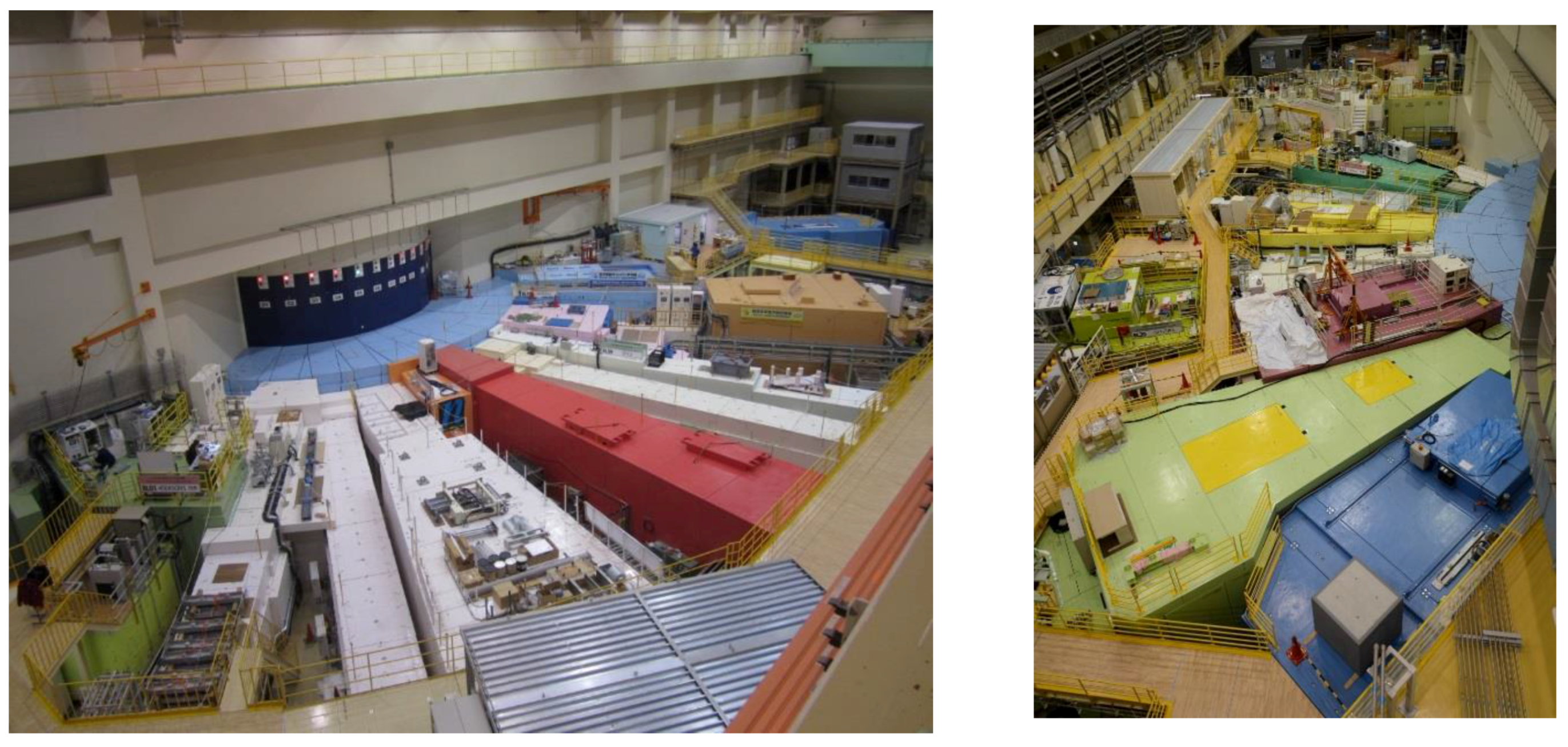
Figure 1. Photo of experimental halls No. 1 (left) and No. 2 (right) of the Materials and Life Science Experimental Facility (MLF).
Qubs 01 00009 g001
Figure 2. Momentum-energy space covered by six spectrometers in MLF [38].
Qubs 01 00009 g002
Figure 3. (a) Schematic view of 4SEASONS [38]; (b) A cryostat for cooling the sample is attached to the vacuum chamber of 4SEASONS.
Qubs 01 00009 g003
Figure 4. Examples of excitation spectra observed at 4SEASONS. The data are shown as functions of momentum and energy of excitations. Colors indicate neutron-scattering intensities: (a) Magnetic excitation spectrum of Pr1.40La0.60CuO4 [45]; (b) Phonon dispersions of Cu obtained by crystal-rotating measurement.
Qubs 01 00009 g004
Figure 5. Layout of HRC. Thick lines indicate arrays of 3He PSDs.
Qubs 01 00009 g005
Figure 6. (a) Spin wave dispersion relationships of SrRuO3 (T = 7 K) and La0.8Sr0.2MnO3 (T = 245 K) observed with NBS at HRC [13]. The black line is a single-crystal result, and the blue line is a fitted curve with E(Q) = DQ2 + Eg. The accessible energy-momentum space in this experiment is below the red line, which is the scan locus of a detector at the scattering angle ϕ = 0.6° with Ei = 100 meV, and the red dotted line is the upper limit of the accessible space for ϕ ≥ 5°; (b) Eg(T) of SrRuO3 [57]. The blue line is a theoretical curve (see text). The inset shows σxy(T) for bulk and film samples, where σ0 is a constant, and the solid line is an empirical function describing σxy(T) for the analysis of Eg(T).
Qubs 01 00009 g006
Figure 7. (a) Photo and (b) schematic view [38] of AMATERAS.
Qubs 01 00009 g007
Figure 8. Schematic POLANO beamline and instruments. Neutron beam coming from left-hand side is injected into vacuum chamber (sample) [38].
Qubs 01 00009 g008
Figure 9. DNA three-dimensional view (a) and inside of the scattering vessel (b).
Qubs 01 00009 g009
Figure 10. Schematic top view of the Modulated Intensity with Zero Effort (MIEZE) and Neutron Resonance Spin Echo (NRSE) spectrometers at BL06.
Qubs 01 00009 g010
Figure 11. (a) Measured time-of-flight (TOF)-MIEZE signal with an effective frequency of 200 kHz; (b) TOF-MIEZE signal between 25 and 25.1 ms, and (c) power spectrum of TOF-MIEZE signal by Fourier transformation.
Qubs 01 00009 g011
Figure 12. d-ranges and peak resolutions of diffractometers in diffraction sub-group. Note that only the covering d-range is plotted for single-crystal diffractometer of iBIX or SENJU.
Qubs 01 00009 g012
Figure 13. (a) 3D-image of SuperHRPD diffractometer. About 1300 PSD detectors are installed, where those with better resolution are in the backward detector bank; (b) Diffraction peak of the horizontal part of the area with the highest scattering angle having Δd/d = 0.0365(1)%.
Qubs 01 00009 g013
Figure 14. (a) Overview of SPICA instrument. The horizontal detector crates are arranged on a cylindrical locus from 2θ = 5º to 175°. (b) Illustration of operando measurements. An 18650-type cell is placed at the center of the sample chamber. The neutron incident beam enters the sample chamber, where it is diffracted by the electrodes, and subsequently reaches the detectors.
Qubs 01 00009 g014
Figure 15. Changes in relationship between discharge/charge time and diffraction profiles of materials in 18,650-type lithium battery.
Qubs 01 00009 g015
Figure 16. Schematic diagram of flowchart for automatic refinement cycle.
Qubs 01 00009 g016
Figure 17. IBARAKI Materials Design Diffractometer, iMATERIA without detector for each bank and instrument shielding. The high-resolution bank, special-environment bank (90° bank), and low-angle bank, can be seen from right to left. The small-angle detector bank, which is not shown in the picture, is situated in the low-angle vacuum chamber (left hand side of the picture).
Qubs 01 00009 g017
Figure 18. Cutaway view of PLANET beamline. The figure shows the setup for experiments using the six-axis press. Reprinted from [72] with permission from Elsevier.
Qubs 01 00009 g018
Figure 19. The appearance of TAKUMI.
Qubs 01 00009 g019
Figure 20. Diffractometer of iBIX.
Qubs 01 00009 g020
Figure 21. (a) Schematic view of SENJU. The sample crystal is set in a vacuum sample chamber. Scattered neutrons are detected by area detectors arranged around the chamber. (b) Sample rotation device for SENJU. A sample crystal fixed on an aluminum rod is set on the sample-mounting table. The sample can be rotated with along the φ and ψ-axes by using piezo-rotators.
Qubs 01 00009 g021
Figure 22. Scattering profile of mesoporous silica measured using TAIKAN.
Qubs 01 00009 g022
Figure 23. Pictures of NOBORU beamline: (a) upstream devices and (b) experiment room, where FL and RC refer to filter exchanger and rotary collimator, respectively.
Qubs 01 00009 g023
Figure 24. Horizontal and vertical views of RADEN.
Qubs 01 00009 g024
Figure 25. Crystal structure of Li10GeP2S12.
Qubs 01 00009 g025
Figure 26. Nuclear scattering length density of lithium atoms in (a) Li10GeP2S12 (LGPS) and (b) Li9.54Si1.74P1.44S11.7Cl0.3 (LSPSC).
Qubs 01 00009 g026
Figure 27. (a) Heat treatment route, dilatometry curve, and comparison of (2, 0, 0) peaks of austenite; (b) Evolution of diffraction profiles. Comparison of bainite transformation kinetics between the direct isothermal bainite transformation (DIT) and partial quenching and bainite transformation (QB) treatment at isothermal temperatures of (c) 573 K or (d) 523 K.
Qubs 01 00009 g027
Figure 28. Chemical diagram of [NiFe]H2ase-mimicking functional model complex, which has a [NiFe] core.
Qubs 01 00009 g028
Figure 29. Fourier maps calculated using single-crystal neutron diffraction data. (left) Fo-Fc map with a structure model in which the deuterium atom was excluded. Positive scattering-length density is observed at the expected position of the deuterium atom between Ni and Fe. (right) Fo-map with a model in which the deuterium atom was included.
Qubs 01 00009 g029
Figure 30. (a) Neutron reflectivity profiles at interface of PMAPS brush–D2O for different NaCl concentrations and the corresponding fitting curves. (b) Volume fraction of brush with respect to the distance from substrate surface evaluated by fitting (retrieved from [151] with permission from the Royal Society of Chemistry).
Qubs 01 00009 g030
Figure 31. (a) Neutron reflectivity profiles at interface of PMPC brush–D2O for different NaCl concentrations and corresponding fitting curves. (b) Volume fraction of brush with respect to distance from substrate surface evaluated by fitting (retrieved from [151] with permission from the Royal Society of Chemistry).
Qubs 01 00009 g031
Figure 32. Excitation spectra of Ba0.5K0.5Fe2As2 and KFe2As2 at 6 K observed using 4SEASONS [48]. (a) The spectrum of Ba0.5K0.5Fe2As2 was measured with incident energy Ei = 409 meV; (b,c) Low- and high-energy excitations of KFe2As2 measured with Ei = 149 meV and Ei = 423 meV, respectively. The horizontal and vertical axes show momentum transfers along the K direction in the orthorhombic cell (in reciprocal lattice units) and energy transfers, respectively. The solid lines in (a,b) are visual guides, and the dashed white lines in (b,c) show the boundaries of the magnetic zone.
Qubs 01 00009 g032
Figure 33. Phase diagram of Ba1−xKxFe2As2 [48]. Open circles, open squares, closed circles, closed squares, and closed diamonds show the Tc, Néel temperature TN, total fluctuating magnetic moment <m2>, bandwidth of the spin-wave-like excitations W, and the incommensurability δ of the magnetic excitations in the reciprocal lattice, respectively.
Qubs 01 00009 g033
Figure 34. (a) Neutron diffraction profile obtained at SuperHRPD (BL08), MLF, J-PARC (retrieved from [108]); (b) Simulated diffraction intensity of magnetic structure shown in inset of Figure 35.
Qubs 01 00009 g034
Figure 35. Magnetic and structural phase diagram of LaFeAsO1−xHx. The TN’s are determined by muon and partly by neutron beams, and the TS’s by X-ray diffraction. The magnetic and crystallographic structure shown in the inset is determined using neutron beam and X-ray diffraction [108].
Qubs 01 00009 g035
Table 1. Neutron instruments at MLF (as of May 2017).
Beam LineModeratorShort NameFormal NameStatusReference
BL01Coupled H24SEASONS4D-Space Access Neutron SpectrometerOperation (2008~)[14]
BL02DNABiomolecular Dynamics SpectrometerOperation (2011~)[12]
BL03iBIXIBARAKI Biological Crystal DiffractometerOperation (2008~)[27,28]
BL04ANNRIAccurate Neutron-Nucleus Reaction Measurement InstrumentOperation (2008~)[34]
BL05NOPNeutron Optics and Fundamental PhysicsOperation (2008~)[35]
BL06VIN ROSEVillage of Neutron Resonance Spin Echo SpectrometersOperation (2017~)[20]
BL07Decoupled Poisoned H2 (thin)Vacant
BL08SuperHRPDSuper High-Resolution Powder DiffractometerOperation (2008~)[21]
BL09SPICASpecial Environment Powder DiffractometerOperation (2011~)[22]
BL10Decoupled H2NOBORUNeutrOn Beam-line for Observation and Research UseOperation (2008~)[36]
BL11PLANETHigh-Pressure Neutron DiffractometerOperation (2013~)[24]
BL12HRCHigh Resolution Chopper SpectrometerOperation (2008~)[15,16]
BL13Coupled H2Vacant
BL14AMATERASCold-Neutron Disk-Chopper SpectrometerOperation (2009~)[9]
BL15TAIKANSmall- and Wide-angle Neutron Scattering InstrumentOperation (2011~)[30]
BL16SOFIASoft Interface AnalyzerOperation (2008~)[31,32]
BL17SHARAKUPolarized Neutron ReflectometerOperation (2011~)[33]
BL18Decoupled Poisoned H2 (thick)SENJUExtreme Environment Single-crystal Neutron DiffractometerOperation (2011~)[29]
BL19TAKUMIEngineering Materials DiffractometerOperation (2008~)[25,26]
BL20iMATERIAIBARAKI Materials Design Diffractometer (Versatile Neutron Diffractometer)Operation (2008~)[23]
BL21Decoupled H2NOVAHigh-Intensity Total DiffractometerOperation (2008~)
BL22RADENEnergy Resolved Neutron Imaging SystemOperation (2015~)[37]
BL23POLANOPolarized Neutron SpectrometerCommissioning[17,18,19]
Table 2. Specifications of 4SEASONS.
BeamlineBL01
ModeratorCoupled hydrogen moderator
Flight path lengthLmoderator-sample = 18 m
Lsample-detector = 2.5 m
Incident energy5–300 meV
Energy resolutionΔE/Ei ≥ 5% FWHM at the elastic line
Detectors3He 1D- position-sensitive detectors (PSD) (16.4 atm partial pressure)
19 mm diameter, 2500 mm long, 352 (266*) tubes
Angular coverage:
−35° – +130° (−35° – +91° *) horizontal
−25° – +27° vertical
(* current values)
Fermi chopperLmoderator-chopper = 16.3 m
Long slit package:
2 mm × 100 mm slots, revolution rate ≤ 350 Hz
Short slit package:
0.4 mm × 20 mm slots, revolution rate ≤ 600 Hz
Slow disk choppersRadius = 350 mm
Revolution rate = 12.5 Hz or 25 Hz
No. 1: Lmoderator-chopper = 9 m, opening angle = 77°
No. 2: Lmoderator-chopper = 12 m, opening angle = 103°
T0 chopperLmoderator-chopper = 8.5 m
Revolution rate = 25 Hz
Beam transportm = 3.2–4 supermirror
Beam size at the sample positionmaximum 45 mm × 45 mm, optimum 20 mm × 20 mm, adjustable by motorized slits
Table 3. Specifications of HRC (see [13,15,16] for details).
BeamlineBL12
ModeratorDecoupled hydrogen moderator
Flight path lengthLmoderator-sample = 15 m
Lsample-detector = 4 m, 5.2 m
Incident energy5–2000 meV
Energy resolutionΔE/Ei = 3–10% (conventional),
ΔE/Ei ≥ 2% (neutron Brillouin scattering (NBS))
Q resolution (designed)ΔQ/ki ≥ 1%
Detector coverage (scattering angle)Horizontal: −31° – +124° (designed)
−31° – +62° (current)
Vertical: −20° – +20°
Detector system3He 1D-PSD [19.05 mm (diameter), 28,000 mm (length)] (256 tubes are currently installed) for 4 m position
3He 1D-PSD [12.7 mm (diameter), 8000 mm (length)] (68 tubes are currently installed) for 5.2 m position
T0 chopperRevolution rate : 25, 50, 100 Hz
Lmoderator-chopper = 9 m
Fermi chopperRevolution rate: 100–600 Hz
Lmoderator-chopper = 14 m
Beam transportm = 3, 3.65 and 4 supermirror
Beam size at sample positionMaximum dimension: 50 mm width × 50 mm height
Table 4. Specifications of AMATERAS (see [9] for details).
BeamlineBL14
ModeratorCoupled hydrogen moderator
Flight path lengthLmoderator-sample = 30 m
Lsample-detector = 4 m
Incident energy (designed)1–80 meV
Energy resolutionΔE/Ei ≥ 1% @ Ei = 20 meV
Q resolution (designed)2% > ΔQ/ki > 0.2%
Detector coverage (scattering angle)Horizontal: −40° – +140° (final state)
+5° – +110° (current state)
Vertical: −16° – +23°
Detector system3He 1D-PSD [φ = 25.4 mm, L = 2910 mm (effective length)]
448 tubes after full installation
(266 tubes are currently installed)
Fast disk choppersRadius 350 mm
Revolution rate ≤ 350 Hz
No. 1 (Pulse shaper) Lmoderator-chopper 7.1 m
No. 2 (Monochromator) Lmoderator-chopper 28.4 m
No. 3 (RRM frame overlap) Lmoderator-chopper 14.2 m
Slow disk choppersRadius 350 mm
Revolution Rate 12.5 Hz or 25 Hz
Opening angle 0°–175° (variable)
No. 1 Lmoderator-chopper 9 m
No. 2 Lmoderator-chopper 13.7 m
Beam transportm = 3 and 3.8 supermirror
Beam size at the sample positionOptimal dimensions for beam are 20 mm width × 10 mm height
The maximum dimensions are 30 mm width × 50 mm height
Table 5. Specifications of POLANO.
BeamlineBL23
ModeratorDecoupled hydrogen moderator
Flight path lengthLmoderator-sample = 17.5 m
Lsample-detector = 2.0 m
Lmonochromating chopper-sample = 1.85 m
Incident energy(unpolarized) 1–500 meV
(polarized) 1–100 meV (designed)
Energy resolutionΔE/Ei ≥ 4% @ elastic
Q resolution (designed)1 to 2% = ΔQ/ki
Detector coverage (scattering angle)Horizontal: −20° to +120°
Vertical: −8° to +8°
Detector system3He 1D-PSD [φ = 19 mm, L = 600 mm (effective length)]
Beam transportm = 4.0 supermirror
Beam size at the sample positionOptimal dimensions for beam are 20 mm width × 20 mm height
The maximum dimensions are 50 mm width × 50 mm height
Table 6. Specifications of DNA.
BeamlineBL02
ModeratorCoupled Hydrogen Moderator
Lmoderator-sample42 m
Lsample-analyzer~ 2.3 m
Lanalyzer-detector~ 2.0 m
Pulse sharpening chopper (PS-chopper)At ~7.5 m from the moderator
Max speed: 300 Hz (designed value)
(Present maximum speed: 225 Hz)
4 slits on one disk
Crystal analyzerCrystal and reflection index
Si(111)
Si(311) in test
Bragg angle of analyzers
~87.5°
Energy resolution~2.4 μeV: Si-111 with 10mm Slit @225Hz of PS-chopper
~3.5 μeV: Si-111 with 30mm Slit @225Hz of PS-chopper
~14 μeV: Si-111 without PS-chopper
~12 μeV: Si-311 with 10mm Slit @225Hz of PS-chopper
Momentum range0.08 < Q < 1.86 Å−1: Si-111
1.0 < Q < 3.80 Å−1: Si-311 (in plan)
Scan energy rangeSi-111
−40 < E/μeV < 100 : Single pulse scan around Ef
−400 < E/μeV < 600 : Multi pulse scan around Ef
−500 < E/μeV < 1500: without PS-chopper in second frame
Si(311)
−150 < E/μeV < 300: Single pulse scan around Ef
(the specifications by the end of March 2017)
Table 7. Specifications of VIN ROSE.
BeamlineBL06
ModeratorCoupled hydrogen moderator
Measured neutron flux and peak wavelength of guide exitMIEZE: 2.7 × 10⁸ n/cm2/s/MW, 4.8 Å
NRSE: 6.9 × 10⁸ n/cm2/s/MW, 5.5 Å
Band disk choppersRadius 200 mm
Revolution Rate 25 or 12.5 (or 8.33) Hz
Opening angle 126° (MIEZE)
Opening angle 162° (NRSE)
Moderator-chopper 12.1 m
Ellipsoid focusing mirror (NRSE)Semi-major axis: 1.25 m
Semi-minor axis: 65.4 mm
Sample size(NRSE) < 5 mm × 5 mm
Wavelength, Q range, Fourier timeMIEZE 3 < λ < 13 Å, 0.2 < Q < 3.5 Å−1, 1 ps < t < 2 ns *1
NRSE 5 < λ < 20 Å, 0.02 < Q < 0.65 Å−1, 0.1 ns < t < 0.1 μs *2
*1 The maximum Fourier time depends on sample size. In the case of a thin film with reflectometry, the maximum Fourier time can be extended. *2 The maximum Fourier time is a first target value. It depends on the performance of ellipsoid-focusing supermirror.
Table 8. Specifications of SuperHRPD.
ModeratorPoisoned Decoupled Hydrogen Moderator
Primary flight path Lmoderator-sample94.2 m
Curved guide31.245 m (m = 3, r = 5 km)
Straight guide51.4 m (m = 3)
Position for disk choppers7.1 m (single), 12.75 m (double)
Backward bank
2θ150° ≤ 2θ ≤ 175°
Lsample-detector2.0–2.3 m
d-range0.3–4.0 Å
Resolution ∆d/d0.03–0.1%
90° scattering bank
2θ60° ≤ 2θ ≤ 125°
Lsample-detector2.0–2.3 m
d-range0.4–7.5 Å
Resolution ∆d/d0.4–0.7%
Low angle scattering bank
2θ10° ≤ 2θ ≤ 40°
Lsample-detector2.0–4.5 m
d-range0.6–45 Å
Resolution ∆d/d0.7–3.0%
Ancillary equipment and sample environmentAuto sample changer (RT, 10 samples)
4 K-type closed cycle refrigerator (4–300 K)
Top-loading refrigerator (10–300 K)
High temperature furnace (950 °C)
m: m-values of supermirror guide; r: curvature radius of curved guide; RT: room temperature.
Table 9. Specifications of SPICA.
ModeratorPoisoned-Decoupled Hydrogen Moderator
Primary flight path Lmoderator-sample52.0 m
Supermirror guide39.4 m (m = 3–6, r = 5 km)
Position for disk choppers7.25, 12.8, 18 m (Single)
Backward bank
2θ149° ≤ 2θ ≤ 172°
Lsample-detector2.0–2.3 m
d-range0.3–4.1 Å *
Resolution ∆d/d0.08–0.15%
High scattering bank
2θ116° ≤ 2θ ≤ 139°
Lsample-detector2.0 m
d-range0.4–4.7 Å *
Resolution ∆d/d0.24–0.33%
90° scattering bank
2θ66° ≤ 2θ ≤ 110°
Lsample-detector2.0 m
d-range0.4–6.0 Å *
Resolution ∆d/d0.37–0.71%
Low angle scattering bank
2θ14° ≤ 2θ ≤ 58°
Lsample-detector2.0 m
d-range0.6–35 Å *
Resolution ∆d/d0.8–2.2%
Ancillary equipment and sample environmentAuto sample changer (RT, 40 samples)
Top-loading refrigerator (10–300 K)
Top-loading cryo-furnace (20–800 K)
m: m-values of supermirror guide; r: curvature radius of curved guide, *d-range is obtained under the 25/3 Hz mode. The frequency can be tuned until 25/5 Hz.
Table 10. Specifications of iMATERIA. The d-range (Q-range) of each bank is the maximum value in the two-measurement mode.
High2θ150° ≤ 2θ ≤ 175°
ResolutionLsample-detector2.0–2.3 m
Bankd-range0.09 ≤ d (Å) ≤ 5.0
Special2θ80° ≤ 2θ ≤ 100°
EnvironmentLsample-detector1.5 m
Bankd-range0.127 ≤ d (Å) ≤ 7.2
Low2θ10° ≤ 2θ ≤ 40°
AngleL21.2–4.5 m
Bankd-range0.37 ≤ d(Å) ≤ 58
Small2θ0.7° ≤ 2θ ≤ 5°
AngleLsample-detector4.5 m
BankQ-range0.007≤ q−1) ≤ 0.6
Table 11. Specifications of PLANET.
CharacteristicsParameters
Moderator20 K Para-hydrogen (decoupled)
Source-to-sample distance25 m
Sample-to-detector distance1.5–1.85 m (depending on the scattering angle)
Detector coverage90° ± 11.3° (horizontal), 0° ± 34.6° (vertical)
Wavelength0.3–6.0 Å
Resolutiond/d = 0.4–0.6%
d-spacing range0.2–4.2 Å (in the single frame mode)
0.2–8.4 Å (in the double frame mode)
Q-value range1.5–30 Å−1 (in the single frame mode)
0.8–30 Å−1 (in the double frame mode)
Neutron flux at sample position in 10 mmφ5.291 × 10⁷ neutrons cm−2 s−1 (@1 MW)
Pressure and temperature range0–16 GPa, RT–2000 K (ATSUHIME)
0–20 GPa, RT (PE-press)
0–10 GPa, 77–473 K (Mito system)
Table 12. Specification of TAKUMI.
ModeratorPoisoned decoupled hydrogen moderator
d-range
  • Standard (25 Hz operation): Δd ~ 0.25 nm (dmin and dmax are tunable)
  • Wide (12.5 Hz operation): Δd ~ 0.50 nm (dmax is about 0.50 nm)
S/N ratio~ 10−3
Peak resolutionTunable ;
Low (~ 0.4 %)
Medium (~ 0.3 %, most cases)
High (~ 0.2 %)
Radial collimators1 mm, 2mm, 5 mm (a pair of each)
Data acquisition
  • Event recording (data reduction with the functions of time, TOF-binning width, and detector range is flexible.)
  • Data reduction based on the physical conditions (load, strain, temperature, etc.) is under development.
Ancillary equipment and sample environment
a)
Large sample table (table size: 700 mm × 700 mm, load capacity: 1 ton)
b)
BL19 Standard loading machine (50 kN)
c)
Furnace system for high temp loading (1273 K), added to (b)
d)
100 K cooling system for loading experiment (100 K – 473 K), added to (b)
e)
Cryogenic loading machine (6 K – 220 K, 50 kN)
f)
Fatigue machine (60 kN, < 30 Hz)
g)
High temperature loading machine for small specimen (25 kN, 1273 K)
h)
Thermo-mechanical simulator (30 kN, 100 mm/s, 1473 K, 30 K/s)
i)
Multipurpose furnace (1273 K)
j)
Multipurpose cryostats (4 K, sample size: 100 × 100 × 100 mm3)
k)
Dilatometer (1273 K)
l)
Eulerian Cradle
m)
Gandolfi goniometer
Table 13. Specifications of iBIX.
ModeratorCoupled
Wavelength of incident neutron0.7–4.0 Å (1st frame)
4.0–8.0 Å (2nd frame)
Neutron intensity (@1MW)0.7 × 10⁶ n/s/mm2
Lmoderator-sample40 m
Lsample-detector500 mm
Solid angle of detectors19.5% for 4π
Detector covered region15.5–168.5°
Detector size133 mm × 133 mm
Detectors pixel size0.52 mm × 0.52 mm
No. of detectors30
Table 14. Specifications of SENJU.
ModeratorPoisoned decoupled
Wavelength of incident neutron0.4–4.4 Å (1st frame)
4.6–8.8 Å (2nd frame)
Neutron intensity (@1 MW)1.3 × 10⁶ n/s/mm2
Lmoderator-sample34.8 m
Lsample-detector800 mm
Solid angle of detectors30.2% for 4π
Detector covered region13.0–167.0°
Detector size256 mm × 256 mm
Detectors pixel size4.0 mm × 4.0 mm
Number of detectors37
Table 15. Specifications of TAIKAN.
BeamlineBL15
ModeratorCoupled hydrogen moderator
Wavelength range0.5–8 Å (unpolarized neutron)
2–8 Å (polarized neutron)
Q range5×10−4–20 Å−1 (unpolarized neutron)
5×10⁻⁴–5 Å−1 (polarized neutron)
Q resolutionΔQ/Q = 0.3 @ Q = 10−2 Å−1, 4.5 × 10⁻² @ Q = 10−1 Å−1, 1.6 × 10⁻² @ Q = 1 Å−1,
3 × 10⁻³ @ Q = 10 Å−1
Detector system3He 1D-PSD [φ = 8 mm, L = 300, 500, 600, 800, 1000 mm (effective length)] 2272 tubes after full installation (1512 tubes are currently installed),
ZnS/6LiF scintillation 2D-ultra-small-angle detector [Spatial resolution: 0.5 mm]
Beam monitorN2 monitor [Efficiency: 10−5 @ 1 Å, 64 mm × 64 mm × 12 mm (effective volume)]
Beam transport3Qc Ni/Ti supermirror guide tube
Polarizer4.5Qc Fe/Si supermirror 4-channel V-cavity
Focusing deviceQuadrupole magnet [dB/dr = 2.25 × 10² T/m],
1st sextupole magnet [dB/dr2 = 5.22 × 10⁴ T/m2],
2nd sextupole magnet [dB/dr2 = 2.43 × 10⁴ T/m2],
Resonance spin flippers
Sample stageDiameter: 700 mm, Weight limit: 750 kgf,
Beam level above the stage: 350 mm
Table 16. List of typical samples, sample size (and beam size), accessible Q range, and exposure time required for full Q-range measurement at SOFIA reflectometer with proton power of 500 kW.
Sample InterfaceSample Size (Beam Size)Q RangeExposure Time
air/Si50.8 mm Ø (30 mm × 40 mm)<2 nm−1¾ h
air/protonated polymer/Si50.8 mm Ø (30 mm × 40 mm)<2 nm−11 h
air/deuterated polymer/Si50.8 mm Ø (30 mm × 40 mm)<4 nm−1½ h
air/D2O25 mL (40 mm × 40 mm)<2 nm−1¼ h
air/no reflection water25 mL (40 mm × 40 mm)<1 nm−13 h
Si/D2O76.2 mm Ø (30 mm × 50 mm)<2 nm−11 h
Si/protonated polymer/D2O76.2 mm Ø (30 mm × 50 mm)<2 nm−11 h
Si/deuterated polymer/H2O76.2 mm Ø (30 mm × 50 mm)<2 nm−11 h
Table 17. Specifications of SOFIA reflectometer.
Wavelength0.2–0.88 nm (single frame)
0.2–1.7 nm (double frame)
Incident angle<6°
Q range<6 nm−1 (depend on reflectivity of a sample)
Table 18. Specification of SHARAKU.
Wavelength0.24–0.88 nm (polarized neutron)
0.11–0.88 nm (unpolarized neutron)
Scattering angle0–18°
Maximum Q8.19 nm−1 (polarized neutron)
17.9 nm−1 (unpolarized neutron)
Table 19. Specifications of NOVA.
BeamlineBL21
ModeratorDecoupled hydrogen moderator
Q range and resolutionDetector bankQ/Q [%]Q-range [Å−1] (d-range[Å])
Small-angle4–500.03–8 (0.8–209)
20°1.7–3.90.2–26 (0.2–31)
45°0.9–1.50.4–50 (0.1–16)
90°0.5–0.71–82 (0.08–6.3)
High-angle0.3–0.351.4–100 (0.06–4.5)
Detector system3He 1D-PSD [φ = 1/2 inch, L = 800 mm (effective length)]
Beam monitorGas Electron Multiplier (B converter, 0.1% efficiency)
Beam SizeTypical size: 6 mm width × 20 mm height
Beam size can be changed from 5 mm×5 mm to 20 mm×20 mm
Table 20. List of available sample environments in NOVA.
ApparatusPurposeSpecification
Sample changerAutomatic sample exchangeSamples per load: 10 or 40
Temperature controlled sample changerAutomatic sample exchange and temp. controlSamples per load: 18
Temperature : 20–700 K
Top load cryostatLow temperatureTemperature : 5–700 K
Vanadium furnaceHigh temperatureTemperature : RT–1373 K
Hydrogen pressure-composition-temperature measurementH2 ab/desorptionTemperature : 50–473 K
Gas pressure : ≤10 MPa H2/D2
Table 21. Specifications of ANNRI.
ModeratorCoupled Supercritical H2
Incident neutron energyEn > 0.0015 eV
SpectrometerGe Spectrometer (Flight path length: 21.5 m)
NaI Spectrometer (Flight path length: 27.9 m)
Neutron intensity (@sample position @1MW)@21.5m sample position
4.3 × 10⁷ n/cm2/s 1.5 meV < En < 25 meV
9.3 × 10⁵ n/cm2/s 0.9 eV < En < 1.1 eV
1.0 × 10⁶ n/cm2/s 0.9 keV < En < 1.1 keV
Sample size and/or volumeUsing the most downstream collimator, neutron beams with diameters of 22, 15, 7 and 6 mm are provided to suit samples of different sizes.
Table 22. Specifications of NOP [35].
ModeratorCoupled Supercritical H2
BranchUnpolarizedPolarizedLow-Divergence
Cross section (Y mm × X mm)50 × 40120 × 6080 × 40
Beam flux (n/cm2/s@1 MW)(3.8 ± 0.3) × 108(4.0 ± 0.3) × 107(5.4 ± 0.5) × 104
Beam Divergence (Y mrad×X mrad)m = 2 equivalent23 × 9.40.23 × 0.23 *1
Luminance (n/cm2/str/s@1MW)(1.8 ± 0.1) × 1011(1.0 ± 0.1) × 1012
Polarization94–96%
*1 For most intense position. Maximum divergence is about 14 mrad × 2.4 mrad.
Table 23. Specifications of NOBORU.
ModeratorDecoupled Supercritical H2
Incident neutron wavelengthλ < 10.5 Å
Resolution (Δλ/λ)0.35% (minimum)
Neutron intensity (@14.0 m sample position @1MW)4.8 × 10⁷ n/s/cm2 (<0.4 eV), 1.2 × 10⁷ n/s/cm2 (>1 MeV),
1.2 × 10⁶ n/s/cm2 (>10 MeV)
Beam collimation ratio (L/D)140, 190, 600 and 1875
Filtersnone/Cd 2 mm/acryl 6 mm
none/Ta 50 µm, In 50 µm, Cu 2 mm/borosilicate glass 1 mm
none/Pb 50 mm/Bi 25 mm
none/Bi 50 mm/Pb 25 mm
Table 24. Specifications of RADEN.
ModeratorDecoupled Supercritical H2
Incident neutron wavelengthλ < 8.8 Å (L = 18m, 25 Hz)
λ < 6.8 Å (L = 23m, 25 Hz)
Resolution (Δλ/λ)0.20% (minimum)
Neutron intensity (@sample position @1MW)9.8 × 10⁷ n/s/cm2 (L/D = 180)
5.8 × 10⁷ n/s/cm2 (L/D = 230)
Beam sizeMaximum 300 mm × 300 mm @23 m sample position
DetectorsCooled CCD (2k × 2k pixels) + ZnS(Li) scintillator, nGEM, μ-NID, Li-glass pixellerated scintillator with multi-anode PMT
Sample environmentLarge (load capacity 1 ton), Medium (load capacity 650 kg), Small sample stage (load capacity 10 kg), Polarization analysis system