Abstract
In recent times, with rapid development in the construction sector, the use of enormous amounts of materials is required for the production of concrete. Fire penetrates concrete, leading to chemical contamination, small cracks, and lightening. These effects can significantly change the properties of concrete’s structure, reduce its strength and durability, and also change the behavior of the structure and lead to effects on the environment. An attempt was made to study the effects of elevated temperature on the mechanical characteristics of self-compacting concrete (SCC) with by-products including fly ash as a partial replacement for cement and waste copper slag as a partial replacement for fine aggregate at 0%, 10%, 20%, 30%, 40%, 50%, 60%, and 70%. The SCC specimens were subjected to elevated temperatures ranging from 200, 400, 600, and 800 °C, respectively, for a steady-state of two hours in a digital muffle furnace. The residual compressive strength, mass loss, ultrasonic pulse velocity, and residual density along with a visual inspection of cracks and color changes were observed. In this study, with over 400 °C temperatures, surface fractures appeared. The residual compressive strength (R-CMS) of all the individual temperatures of the SCC-WCS% mixes exhibited a gain in strength range from 31 to 34 MPa at 400 °C, 26 to 35 MPa at 600 °C, and 22.5 MPa to 33.5 MPa at 800 °C, respectively. Microstructural analysis of SCC-WCS% mixtures subjected to elevated ambient temperatures is carried out with a scanning electron microscope (SEM) and X-ray diffraction (XRD).
1. Introduction
The usage of concrete containingordinary Portland cement (OPC) around the world has greatly increased, leading to an increasedproduction of cement, which eventually leads to the exhaustion of natural resources [1]. Under these conditions, the use of self-compacting concrete (SCC) made from by-products of industrial wastesfullfills the requirements of the construction sector [2,3]. SCC offers excellent deformability and segregation resistance and may be poured in heavily reinforced or restricted areas without internal or external vibrations [4,5]. SCC was developed in Japan in the late 1980s and has recently gained popularity for structural configurations and applications in several nations [6]. A fire can cause significant damage to buildings. During times of extreme heat, structures are rendered uninhabitable [7,8]. For a variety of reasons, high temperatures have a detrimental effect on the materials used in construction [9]. Damage to concrete can result from the breakdown of hydration products and the thermal expansion of concrete components [10]. Concrete is a critical component in the construction industry [11,12]. Solid and liquid phases make up the majority of concrete, which is composed of cement paste with particles, as well as water in the concrete pores. When concreteis exposed to fire, concrete’s matrix phases are affected, leading to a gradual transition from the liquid phase to a gas phase matrix (vapor). Additionally, a fire near a concrete slab can increase internal stresses and changes in slab thickness, jeopardizing structural section safety [13,14].
Based on the effect of fire on concrete, the experimental results observed are as follows. Wei Gong and Takao Ueda’s results showed that the compressive strength of concrete decreased when copper slag fine aggregate was used, but the residual compressive strength increased after heating to 300 °C. The inclusion of fine copper slag aggregate in concrete reduces the residual elastic elasticity and speeds up Cl penetration into self-compacting concrete when temperatures exceed 200 °C [15]. Iman Afshoon and Yasser Sharifi observed that high temperatures (100 °C to 800 °C) have an influence on the use of ground copper slag (GCS) in SCC as a replacement for cement. GCS replacement may enhance SCC by up to 15%. At all temperatures, 5% replacement yields the best performance. There was a noticeable decrease in performance at high temperatures when the replacement percentage was increased from 20% to 25% and 30% [16]. Quian et al. noted an increase in PC mortar strength until 200 °C, but beyond that, the strength of the mortar decreased, while the strength of alkali-activated copper slag mortars rose considerably from 200 °C to over 800 °C [17].In Mehdi Mohit et al.’s work, a mortar sample containing CWP was shown to have higher heat resistance. It was found that the CWP-containing mixes had a lower portlandite peak intensity than the control mix, and SEM pictures indicated that CWP reduced porosity [18]. R. Jaskulski et al. observed that concrete constructed using copper slag is more environmentally friendly than traditional concrete, and it also has comparable mechanical properties and is more energy-efficient since it has a lower thermal conductivity coefficient than traditional concrete, according to the findings of their study [19]. Binaya Patnaik et al. observed 0.5 and 0.55 ratios of cement to water, with steel fiber volume fractions of 0 to 0.5; 1.0 to 1.5 are under investigation. The experiment involved 28 and 56 heat cycles. The results demonstrated that copper slag concrete mixes are substantially more heat-resistant than standard concrete mixtures [20]. In Sungwon Sim et al.’s work, bricks that had copper slag added to them were tested. According to the results, the incorporation of copper slag significantly improved the mortar’s flowability and strength. The gamma-ray attenuation of silica was dramatically reduced when copper slag was used as an aggregate [21].The purpose of Ulla Khan, A et al.’s study was to investigate the SCC core and steel tube behavior at elevated temperatures from 100 °C to 800 °C for each tested material. Experiments were conducted on laminated steel plates filled with different types of SCC (M25, M30, and M40) under pressure and high temperature. This study developed an axial cross section to determine key factors such as the mass strength, including load bearing, of SCCFST [22]. In M. Manikanta et al.’s work, the impact of slag-cement fly ash (SCFA) and varying quantities of fly ash (0%, 10%, 15%, and 20%) on composites was studied when cement was partially replaced at248 cubic meters with a 150 mm diameter. The model M30 was eliminated. When compared to the identical concrete at room temperature, the impact strength of the chosen cubes that were treated with 15% fly ash and SCBA and allowed to cure for 28 days was greater [23].
Little research has been conducted on the thermal attributes of SCC mixes using WCS as an alternative to fine aggregate. Due to research limitations regarding WCS as a fine aggregate substitute in SCC, an experimental investigation of SCC-WCS% of mixes by replacing natural sand with waste copper slag(WCS) at 0%, 10%, 20%, 30%, 40%, 50%, 60%, and 70% was conducted. Residual compressive strength, mass loss, residual density, non-destructive testing, and microstructural analyses were performed on SCC-WCS% mixes at elevated temperatures of 200 °C, 400 °C, 600 °C, and 800 °C, respectively.
2. Research Significance
As a part of India’s economic growth, the construction sector is expanding at a fast rate. The use of non-renewable natural resources and the large emissions of CO2 during production due to the growing demand for concrete materials pose an environmental risk. In 2027, India will have the second-largest aggregate market in the world. As a consequence of the copper refining process, waste copper slag output skyrocketed due to an increase in demand for copper and its derivatives brought on by population growth. When a tonne of copper is produced, around 2.2–3.0 tonnes of WCS are generated. The chemical and physical properties of WCS are suitable for use as SCM aggregate in concrete. Efforts are being undertaken to improve the sustainability of concrete. The SCC has a critical role to play in the development of infrastructure. Nowadays, flyash has become a principal material in concrete mixes, but it was a waste, causing many problems in the past. Likewise, WCS has the potential to become a principal material in concrete in the future. Hence, studies on the use of copper slag in SCC have significance.
3. Methodology
To ensure sustainability and the conservation of natural resources, industrial waste such as fly ash and waste copper slag has the potential to replace cement and fine aggregate in the production of SCC. In this study, the cement was replaced with flyash at 17.85% in all mixes, which is constant, and natural sand was substituted by WCS at various percentages from 0% to 70%.Based on the above consideration, a total of eight mixes were prepared to assess the SCC-WCS% mixes as per EFNARC [24,25], IS 10262:2019 [26] recommended testing. The properties of the SCC-WCS% mixes that were subjected to elevated temperatures at 200 °C, 400 °C, 600 °C, and 800 °C for a 2-h steady-state duration were also studied. The present work proposes to study residual compressive strength [27], density [28], ultrasonic pulse velocity [29], mass loss, and microstructural analyses like SEM and XRD for the SCC-WCS% mixes.
4. Experimental Materials
4.1. Materials
The OPC 53 grade utilized in this investigation complies with the requirements of IS: 12269–2015 [30]. VTPS, Vijayawada, Andhra Pradesh, India, provided the fly ash (FA). From the neighbouring region, fine and coarse aggregates (ranging in diameter from 10 to 12.5 mm) were gathered from Guntur, Andhra Pradesh, India. Sri Srinivasa Metallizers, Hyderabad, India, provided the waste copper slag (WCS). Figure 1 represents the grading curves of aggregates used in the study. Table 1 and Table 2 represent the chemical characteristics and the physical properties of materials, respectively. Figure 2 shows the view of copper slag waste. A high range water reducer (HRWR) with a specific gravity of 1.09 as per IS 9103:1999 [31] was utilized to obtain the flow parameters of the SCC-WCS% mixes. It was shown that HRWR with a pH of more than six and less than 0.2 percent chloride ion concentration and a solids content of at least 30 percent by weight was the most effective. SCC-WCS% mixtures were prepared using tap water in the laboratory.
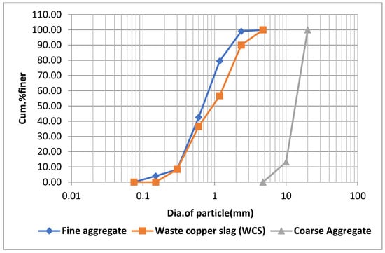
Figure 1.
Grading curves of aggregates used in the study.

Table 1.
Chemical properties of materials for SCC-WCS% mixes.

Table 2.
Observed physical properties of materials for SCC-WCS% mixes.
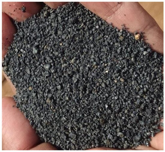
Figure 2.
Waste copper slag as fine aggregate used in the study.
4.2. Mix Proportion Details
In this study, flyash replaced cement at a constant 17.85% in all mixes, while WCS substituted natural sand at various percentages ranging from 0% to 70%.According to our findings, a total of eight mixes were prepared to assess the SCC-WCS% mixes as per EFNARC recommended testing. The following is the optimal SCC mix ratio: 425 kg/m3 cement, 92.35 kg/m3 flyash, 904 kg/m3 coarse-grain-crushed aggregates, 740 kg/m3 natural sand, and 0.43 water to cement. In the laboratory, PCE super plasticizer at 4.17 kg/m3 and tap water were used to make mixtures. For a homogeneous mixture, the SCC was prepared in the pan mixer for approximately 8–10 min. According to EFNARC [24,25] and IS 10262:2019 [26], the flow properties were assessed. “WCS0%” refers to the control SCC mixture with a sand content of 100%. As an example, an SCC combination containing 10% WCS is called “WCS10%”, whereas other mixes are referred to as “WCS70%”, and so on. A total of eight mixers, including a control mixture, were created. SCC was put into molds after workability testing. Samples were demolded after 24 h of curing and until the time of testing in the laboratory. Cube specimens with a size of 100 × 100 × 100 mm were manufactured in the laboratory according to IS 516:2015 [27].
4.3. Testing Methods
4.3.1. Heating and Cooling Regime
An electrical furnace with a capacity of 1200 °C was used for the study. The cube specimens were subjected to testing at 200, 400, 600, and 800 °C, respectively, after 28 days of curing [34]. The increasing heating rate of the automatic electric furnace was 5 °C/min. The specimens were kept at a steady state for 2 h. After that, the specimens were kept at room temperature in the laboratory to cool down. The residual compressive strength, mass loss, and UPV tests were conducted. After performing the compressive strength test (CMS), we collected a small sample from the tested specimens and subjected them to elevated temperatures of 200, 400, 600, and 800 °C, respectively. Using the collected small samples, we assessed the XRD and SEM for SCC-WCS% mixes. Figure 3 represents the digital electric furnace used in the study.
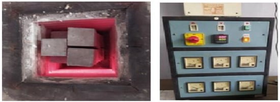
Figure 3.
The electrical thermal furnace used for the study.
4.3.2. Residual Compressive Strength Test
The residual compressive strength test (R-CMS) of SCC with WCS addition as fine aggregate was observed at different temperatures ranging from 27, 200, 400, 600, and 800 °C in a steady state for 2 h. The cube samples, which were subjected to elevated temperatures, were tested using a universal testing machine (UTM) with a 100 tone capacity.
4.3.3. Ultrasonic Pulse Velocity Test
The ultrasonic pulse velocity test (UPV) is conducted to assess the quality of concrete. In this study, the SCC-WCS% mixes adopted the direct technique. In this technique, the two transducers are positioned opposite one another to generate and receive signal waves. Based on the signal waves, the velocity is assessed depending on the sample distance travelled by the waves, which is the side length of the cube. From the obtained velocity, the quality of concrete is shown in Table 3, which is assessed as per IS 13311-1 [29]. Figure 4 shows the view of UPV apparatus testing and the display of velocity.

Table 3.
Velocity for concrete quality as per IS 13311-1 [29].

Figure 4.
UPV test equipment used in the study.
4.3.4. Mass Loss
The mass loss of the SCC-WCS% mixes which were subjected to elevated temperatures was calculated by measuring the mass of the cube samples before and after heating. The reduction in the mass of the cube sample after treatment at high temperatures is due to the dehydration of the cement matrix. It relates to the quality of the concrete.
4.3.5. Color and Cracks
The preliminary opinion on the extent of damage can be framed by visual inspection. The color changes and surface cracks observed on cube specimens subjected to elevated temperatures were observed by visual inspection.
4.4. Micro Scale Analysis of Specimens
Microstructural analysis is very much needed to investigate the crystalline structure and morphology of the SCC-WCS% mix samples. SEM was performed on the sample retrieved from the inner core of SCC samples after performing the compressive strength test. Scanning electron microscopy (SEM) is an electron microscope that creates pictures of a sample using a surface-focused beam of electrons. The backscattered electron imaging capabilities of the SEM, VEG3, and SBHTESCAN were used for the investigation. In addition, SCC-WCS% mix powder samples were also analyzed by X-ray diffraction (XRD). SEM and XRD tests were performed on SCC-WCS% mixes, which were subjected to ambient and elevated temperatures of 200, 400, 600, and 800 °C, respectively.
5. Results and Discussion
5.1. Residual Compressive Strength Results
Figure 5, represents the R-CMS of SCC-WCS% mixes at elevated temperatures. The CMS results at 27 °C are 33, 37.5, 44.5, 47, 55, 52, 48, and 43 MPa, while the R-CMS results at 200 °C are 35, 36, 42, 43, 47, 44, 45, and 44 MPa, respectively; at 400 °C, the R-CMS results are 31, 29, 32, 34, 38, 37, 36, and 35 MPa; at 600 °C, the R-CMS results are 30, 26, 27, 33, 35, 32, 30.5, and 27 MPa; and at 800 °C, the R-CMS results are 23, 22.5, 24.5, 30, 33.5, 30, 29.2, and 24.5 MPa at 0%,10%, 20%, 30%, 40%, 50%, 60%, and 70% WCS substitution with sand in SCC mixes. Due to the effect of elevated temperature, a slight decrement in strength is recorded, ranging from 6% to 30.9% at 400 °C, 9% to 39.3% at 600 °C, and 30% to 44.9% for 800 °C compared with the R-CMS of SCC-WCS0% at the relevant temperature mix. This is due to water escaping from the matrix and creating cavities, leading to a drop in CMS, and by breaking the ITZ, resulting in micro–macro expansions in SCC-WCS% mixtures [15]. When compared with the R-CMS of WCS0%,the variation in R-CMS of SCC-WCS% mixes ranges as follows: 2.85% to 22.5% at 200 °C, 3.22% to 19.35% at 400 °C, 6.6% to 29.2% at 600 °C, and 6.52% to 36.73% at 800 °C. Figure 6 depicts the changes in R-CSM compared with SCC-WCS0% at respective temperatures. At elevated temperatures, all mixes show an incremental trend in R-CSM up to 400 °C. The R-CMS is increased from 3% to 45.45% at 200 °C and 3.03% to 15.15% at 400 °C. But the WCS10% and WCS20% mixes exhibit a decrement of 6%, 12.12%, and 3% at 400 °C. After that, there is a moderate decrement of about 3% to 21% at 600 °C and 9% to 60% at 800 °C. The R-CMS of the SCC-WCS% mixes ranges from 31 to 34 MPa at 400 °C, 26 to 35 MPa at 600 °C, and 22.5 MPa to 33.5 MPa at 800 °C, as shown in Figure 6.
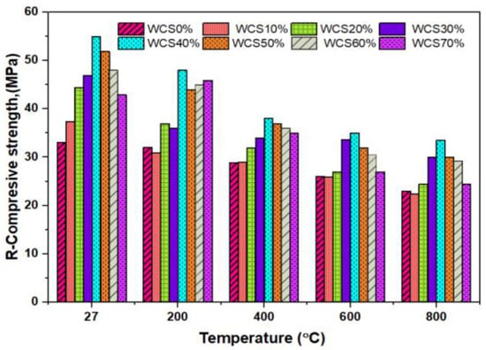
Figure 5.
R-CMS of SCC-WCS mixes at elevated temperature.
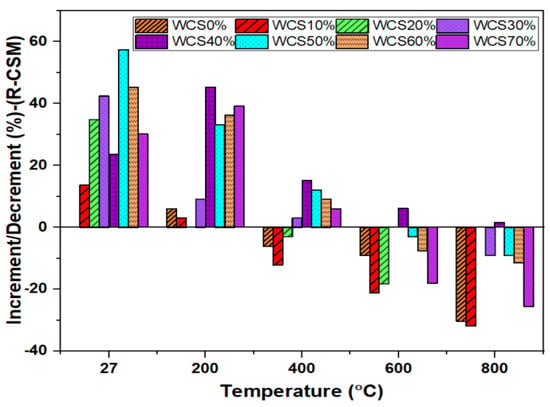
Figure 6.
Increment/decrement (%) RCMS for SCC-WCS mixes at elevated temperature.
The principal causes of concrete strength loss at increased temperatures are changing hydrothermal conditions, which also involve physical and chemical changes such as aggregate expansion and C-S-H gel shrinkage. These alterations occur in three distinct phases, identified in the literature and this study as follows:
- At 200 °C, concrete compressive strength is moderately increased as a result of C-S-H rehydration when water migrates and condenses in the sample’s cooler parts. The hydration of a heated cement paste is achievable by forming a new C-S-H gel from the new nesosilicate, which is validated by a CaO/SiO2 ratio similar to the first C-S-H gel and recovery of its initial stoichiometry. This is most likely due to flyash; secondary C-S-H gel is generated in addition, and the spalling has a homogeneous matrix. Concrete performs well at normal temperatures, but at higher temperatures, there is a minor decrease in performance when cement is replaced with pulverized copper slag [16,17].
- Between 400 and 600 °C, concrete’s compressive strength reduces significantly owing to high WCS%, low SWA, and physical and chemical degradation, resulting in voids, cavities, and micro-fractures, as well as disintegration of the C-S-H gel at temperatures between 400 and 600 °C. The presence of Si and Ca in the concrete matrix phase results in the accumulation of the CSH layer, which causes the concrete to become a denser gel at the IT zone, resulting in the production of aluminosilicate gel [35,36] in the SCC matrix.
- At 800 °C, concrete compressive strength has practically failed. However, in this investigation, the test was ended at 800 °C.
All SCC-WCS% shows an improvement in the performance of R-CMS when subjected to elevated temperatures compared with the control mix at the respective temperature. The results of SCC-WCS% with 40% to 60%WCS mixes show a maximum R-CMS than with the control mix at the respective temperatures. The hydration process of the SCC matrix results in a continuous homogeneous and denser C-S-H gel at ambient and elevated temperatures ranging from 200 to 800 °C, leading to an increment in CMS of up to 50%. In AAS, mortar made with 20% copper slag exhibits an optimum performance at elevated temperatures up to 800 °C, leading to an increment in CMS of up to 50%. Based on the elevated temperatures, the regression analysis is performed on SCC-WCS% mixes as shown in Figure 7. It represents the correlation of the R-CMS of SCC-WCS% mixes at the elevated temperatures. The correlation coefficients are obtained from R-CMS to CMS at 200 °C, 400 °C, 600 °C, and 800 °C for SCC-WCS% mixes as follows: R2 is 0.944, 0.889, 0.725, and 0.706.For all the mixes, the deviation of error is 6% at 200 °C, 11% at 400 °C, 17% at 600 °C, and 30% at 800 °C with the SCC mixes.
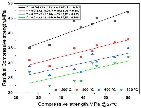
Figure 7.
Regression analysis of R-CMS for SCC-WCS mixes at elevated temperature.
5.2. Ultrasonic Pulse Velocity
Figure 8 shows the UPV values of the SCC-WCS mix subjected to elevated temperatures of 27 °C, 200 °C, 400 °C, 600 °C, and 800 °C. The following are the UPV results of SCC-WCS% mixes at ambient and elevated temperatures: At ambient temperature, the UPV results are 4925, 5000, 5150, 5200, 5267, 5220, and 5108 m/s. At 200 °C, the UPV results are 4545 m/s for WCS0%,and the WCS10% to 70% results are 4608, 4695, 4717, 4673, and 4695 m/s, respectively. At 400 °C, UPV results at WCS0% are 3460 m/s, and at WCS10% to 70% results are 4237, 3931, 3723, 3771, 3831, 3190, and 2870 m/s, respectively. At 600 °C, UPV results at WCS0% are 1408 m/s, while WCS10% to 70% UPV results are 1468, 1976, 2786, 3108, 2309, 2066, and 2278 m/s. At 800 °C, UPV results at WCS0% are 1400 m/s, while the WCS10% to 70% results are 1450, 1825, 2635, 3005, 2255, 1995, and 2150 m/s respectively. The results showed the UPV values were a slight drop from 27 °C to 200 °C. The decrement is very low, below 3%. At 400 °C, WCS60% shows a 7.8% decrement and WCS70% shows a 17% decrement. In all elevated temperatures, sand substitution with WCS in SCC mixes exhibits a good quality of concrete compared to SCC-WCS0% (CC) as per the recommended code listed in Table 3.
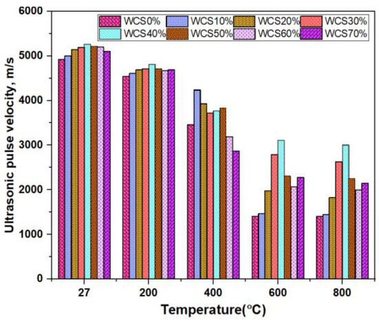
Figure 8.
UPV of SCC-WCS mixes at elevated temperature.
At ambient and 200 °C temperatures, the quality of concrete is excellent [29,35]. At 400 °C–800 °C, the concrete quality ranges from excellent to good at WCS40% to WCS70% in SCC mixes, and WCS10% to 30% shows a drop in UPV values, indicating that the concrete quality is moderate to doubtful. The decrement in UPV is due to the decomposition of C-S-H gel and a rise in capillary pores. These reduced transfer velocity along with voids and pores, are observed in the microstructure.
5.3. Mass Loss
Figure 9, shows the mass loss at different high temperatures for SCC-WCS% mixtures. The mass loss results in SCC-WCS% mixtures at 200 °C are 4.65% for WCS0% and the WCS10% to 70% mass loss results are 4%, 4.1%, 4.3%, 4.9%, 4.8%, 4.5% and 4.2%. At 400 °C, it is 4.5% for WCS0%, and the WCS10% to 70% mass loss results are 4.2%, 4.5%, 4.7%, 5%, 5.1%, 5%, and 5%. At 600 °C, the WCS0% is 7%, and the WCS10% to 70% mass loss results are 8.2%, 8.16%, 6.56%, 6.36%, 6.32%, 6.85%, and 4.8% mass loss. At 800 °C, the WCS0% is 10% and the WCS10% to 70% mass loss results in 9%, 9.21%, 7%, 6%, 6.1%, 6.5%, and 8%, respectively.
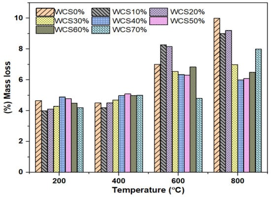
Figure 9.
Mass loss (%) of SCC-WCS mixes at elevated temperature.
The primary causes of mass loss in SCC-WCS% mixtures at increased temperatures during three separate phases, found in the literature and our work, are as follows:
- At 200 °C, this leads to the oozing of water from the concrete, which causes mass loss in SCC-WCS% mixes.
- At 400 °C, the mass loss was mostly caused by degradation of the SCC bond, collapse of C-S-H gels, and evaporation of water in the capillary pores of the concrete [18]. At 400 °C, the mass loss is below 5.2% for all the samples.
- At 600–800 °C, the high temperatures cause the hydration matrix to collapse; eventually, water evaporation in the concrete matrix causes mass loss. In this instance, the cement paste culminates in the breakage ofthe needed strength. As a result, bond breaking is easier at ITZ, and disintegration occurs faster in the SCC matrix. The phenomenon can be linked to rapid weight reduction. The XRD show the degradation of portlandite, calcium hydroxide, and quartz, which results in mass loss in the SCC matrix [37]. At 600 and 800 °C, mass loss is less than 8.2% and 9.2% for all samples.
The mass loss in SCC-WCS% mixes at 200 °C is less than 10%. At 400 °C for SCC-WCS% mixes, at WCS10% in the SCC mix shows the lowest at 6.6% and the highest at 13.33% mass loss, for WCS50%, respectively. The mass-loss rate increases from 600 °C to 800 °C due to the high evaporation of water, while paste decomposition creates voids in the concrete. In general, mass loss at high temperatures is common in all conventional concrete [15,16].
5.4. Residual Density
Figure 10 depicts the residual density (R-D) of SCC-WCS% mixes at ambient and elevated temperatures of 27 °C, 200 °C, 400 °C, 600 °C, and 800 °C. The residual density of mixes exhibits an incremental trend with WCS content at elevated temperatures. Figure 10 shows the R-D, at 27 °C ranging from 2400 to 2650 kg/m3, at 200 °C ranging from 2302 to 2555 kg/m3, at 400 °C ranging from 2272 to 2396 kg/m3, at 600 °C ranging from 2000 to 2345 kg/m3, and at 800 °C ranging from 1855 to 2250 kg/m3. The density of the SCC-WCS% mixes at 27 °C shows an increment of about 2.8% to 10.41% at 200 °C, 400 °C, 600 °C, and 800 °C. The slight decrement in R-D ranges from 3.5 to 6.9%, 5.3 to 11.9%, 7.78 to 20%, and 10 to 29.3% compared with ambient temperature for SCC-WCS mixes. Figure 10, exhibits an incremental trend in density compared with the control mixture (SCC-WCS0%) at elevated temperatures of 27 °C, 200 °C, 400 °C, 600 °C, and 800 °C. However, the decrement for WCS at 10% and 60% is 0.52% and 5.35% for 400 °C, while the decrement for WCS at 20%, 40%, and 70% is 10.26%, 0.42%, 2.08%, and 10.1%, 2.22%, and 3.43% for 600 °C and 800 °C, respectively.
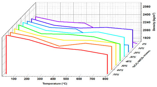
Figure 10.
Residual density R-D of SCC-WCS% mixes.
5.5. Visual Observation
Figure 11 shows pictures of the surface of SCC-WCS% mixtures treated at elevated temperatures ranging from 200 to 800 °C. The SCC-WCS% mixes show no significant crack up to 600 °C, but the increase in temperature causes void spots on the surface. Figure 11c shows a crack in the WCS0% mix at 400 °C. In Figure 11d, at a higher temperature of 800 °C cracks are observed in SCC-WCS% mixes. It is chemical decomposition that leads to crack creation [16]. All the samples show color alterations between 400 °Cand 800 °C. The samples exhibit a dark gray colour at temperature of 400 °C and become lighter when the temperature increases to 800 °C [18].
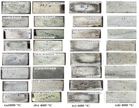
Figure 11.
Surface picture SCC-WCS% mixes samples: (a) 200 °C, (b) 400 °C, (c) 400 °C, and (d) 800 °C.
5.6. Micro Structure Analysis
Microstructure analysis was performed on SCC-WCS% mix samples at ambient and elevated temperatures of 200, 400, 600, and 800 °C, respectively, to understand the crystalline structure and morphology.
5.6.1. X-ray Diffraction (XRD) Analysis
The phases of the concrete matrix were measured with X-ray diffraction (XRD). XRD phases are presented for SCC mixes at sand replacement with WCS from 0% to 70%. Powder samples were taken from the SCC-WCS mixes after CSM at 28 days of curing. XRD was performed at 2θ, ranging from 5 to 90 degrees. The XRD patterns for SCC-WCS% mixes at elevated temperatures ranging from 27 °C to 200 °C, 400 °C, 600 °C, and 800 °C are shown in Figure 12, Figure 13, Figure 14, Figure 15, Figure 16 and Figure 17. The SCC-WCS% mixes contained multi-phase peaks. The main peak phases of the SCC mix at 0% WCS at elevated temperatures are as follows: at 27 °C, 200 °C, 400 °C, 600 °C, and 800 °C, the peak phases are quartz and calcium hydroxide, as shown in Figure 12. The main peak phases of the SCC mix at 20% and 30% WCS at elevated temperatures are as follows: at 27 °C, 200 °C, 400 °C, 600 °C, and 800 °C, the peak phases are quartz, anorthite, portlandite, and calcium hydroxide, as shown in Figure 13 and Figure 14.
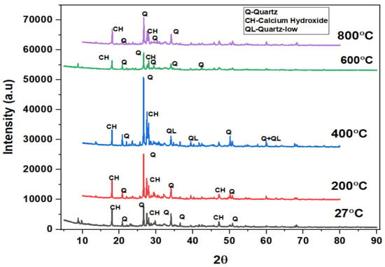
Figure 12.
XRD pattern of SCC mixes at 0%WCS at different temperatures.
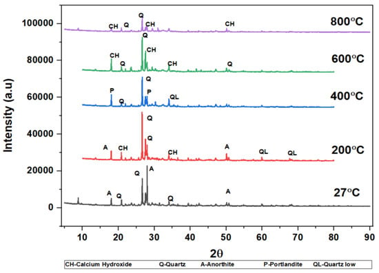
Figure 13.
XRD pattern of SCC mixes at 20%WCS at different temperatures.
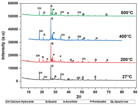
Figure 14.
XRD pattern of SCC mixes at 30%WCS at different temperatures.
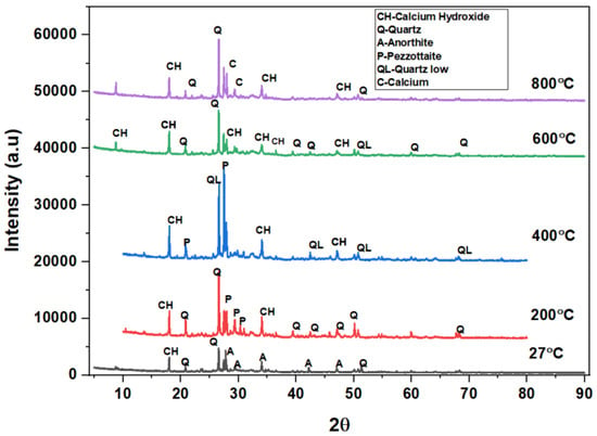
Figure 15.
XRD pattern of SCC mixes at 40%WCS at different temperatures.
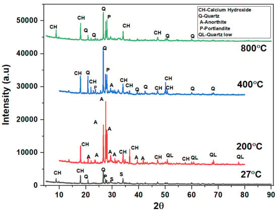
Figure 16.
XRD pattern of SCC mixes at 60%WCS at different temperatures.
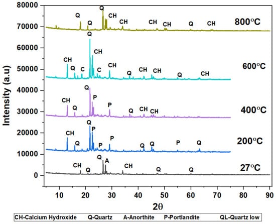
Figure 17.
XRD pattern of SCC mixes at 70%WCS at different temperatures.
The main peak phases of the SCC mix at 40% WCS at elevated temperatures are as follows: As shown in Figure 15,quartz, anorthite, portlandite, calcium hydroxide, pezzottaite, calcium, and quartz have low melting points at 27 °C, 200 °C, 400 °C, 600 °C, and 800 °C. The main peak phases of the SCC mix at 60% and 70% WCS at elevated temperatures are as follows: as shown in Figure 16 and Figure 17, the peak phases were quartz, anorthite, portlandite, calcium hydroxide, and quartz low at elevated temperatures. The quartz-synthetic phase ICSD-01-085-1053 exhibited a hexagonal crystal shape in the major peak phases of all increased temperature combinations. Anorthite and calcium hydroxide were also found in the sample. CaAlSi2O8 and Ca(OH)2 are the chemical formulas for anorthite and calcium hydroxide, respectively [37,38].
Figure 12, Figure 13, Figure 14, Figure 15, Figure 16 and Figure 17 illustrate SCC-WCS mixes with lower intensities of peaks of quartz, anorthite, portlandite, and calcium hydroxide due to elevated temperatures of 400 °C, 600 °C, and 800 °C. Due to thermal effects, the breakdown of peak intensity is observed in quartz, anorthite, portlandite, and calcium hydroxide, which leads to a decrease in the compressive strength of the mixes.
5.6.2. SEM Analysis
The microstructure is studied from SEM images at ambient temperature and elevated temperatures of 200, 400, 600, and 800 °C, respectively, after 28 days of curing for SCC mixes with sand replacement with WCS from 0% to 70%, shown in Figure 18, Figure 19, Figure 20, Figure 21, Figure 22 and Figure 23. Figure 18a–e represent an SEM image of WCS0% in SCC mixes after 28 days of curing at room and elevated temperatures. Figure 18a depicts an SEM image of C-S-H gel at 27 °C with small cracks and voids. Figure 18b represents a 200 °C SEM image that shows voids and gaps which are observed in the microstructure, and needle-like structures observed with a dense C-S-H gel. At 400 °C, Figure 18c depicts needle-like ettringite structures and air voids in the concrete matrix. Figure 18d depicts voids and cavities at 600 °C. Due to the elevated temperature expulsion of water in the concrete matrix, serious air gaps are observed, leading to a change in the chemical bond of the interfacial transition zone (ITZ), but some parts show denser C-S-H gel formation [39,40,41,42,43,44,45,46]. As seen in Figure 18e, at 800 °C, due to elevated temperatures, more water escapes from the matrix, leading to a large number of voids and cracks appearing in the microstructure. Figure 19a–e shows an SEM image of WCS at 20% in SCC mixes after 28 days of curing at room temperature and higher temperatures.
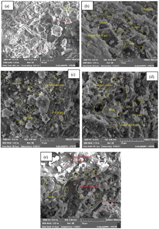
Figure 18.
SEM image of SCC mix at 0%WCS samples thermally treated at (a) 27 °C, (b) 200 °C, (c) 400 °C, (d) 600 °C, and (e) 800 °C.
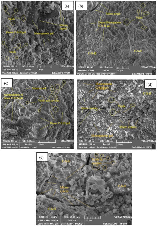
Figure 19.
SEM image of SCC mix at 20% WCS samples thermally treated at (a) 27 °C, (b) 200 °C, (c) 400 °C, (d) 600 °C, and (e) 800 °C.
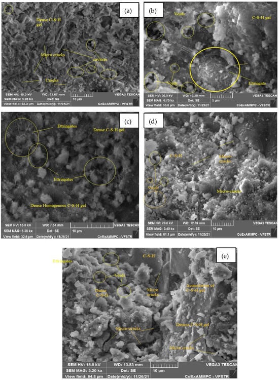
Figure 20.
SEM image of SCC mix at 30% WCS samples thermally treated at (a) 27 °C, (b) 200 °C, (c) 400 °C, (d) 600 °C, and (e) 800 °C.
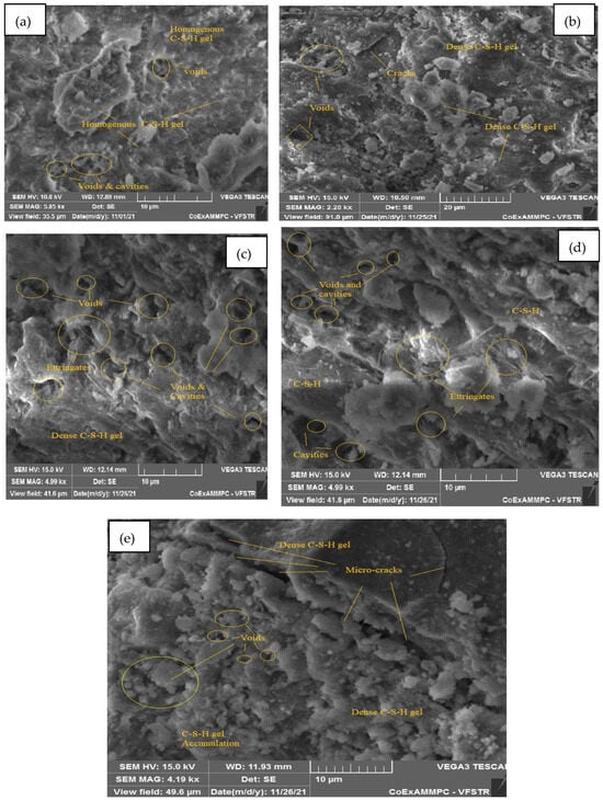
Figure 21.
SEM image of SCC mix at 40% WCS samples thermally treated at (a) 27 °C, (b) 200 °C, (c) 400 °C, (d) 600 °C, and (e) 800 °C.
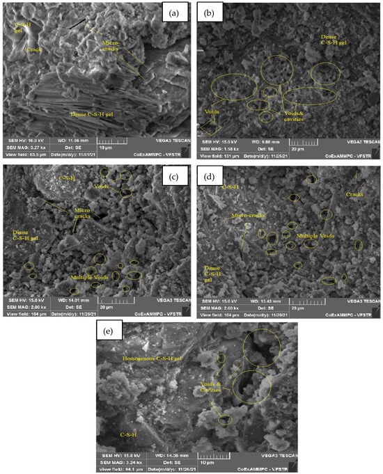
Figure 22.
SEM image of SCC mix at 60% WCS samples thermally treated at (a) 27 °C, (b) 200 °C, (c) 400 °C, (d) 600 °C, and (e) 800 °C.
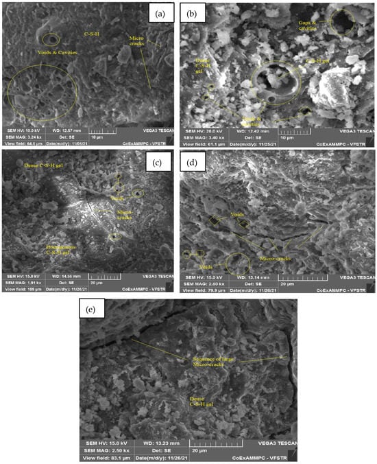
Figure 23.
SEM image of SCC mix at 70% WCS samples thermally treated at (a) 27 °C, (b) 200 °C, (c) 400 °C, (d) 600 °C, and (e) 800 °C.
In Figure 19a, at 27 °C, the present micrograph images exhibit the presence of amorphous C-S-H gel and CH. They show the formation of microcracks, and voids are observed. Figure 19b, at 200 °C, shows a dense, homogenous C-S-H gel with certain microcracks and voids. Figure 19c, at 400 °C, shows the accumulation of a dense C-S-H gel, microcracks, voids, and cavities in the SCC-WCS% mixture. In Figure 19d, at 600 °C, microcracks are visible in a dense, homogeneous C-S-H gel with voids. Figure 19e, at 800 °C, shows that the evaporation of water present in the concrete matrix leads to voids and cavities, which lead to microcracks and changes the chemical bonds.
Figure 20a–e represent an SEM image of WCS30% in SCC mixes after 28 days of curing at room and elevated temperatures. Figure 20a, at 27 °C, presents an enriched microstructure with a denser C-S-H gel, and certain micro cracks and cavities are also observed. In Figure 20b, at 200 °C, the morphology of the SEM image shows a dense C-S-H gel; ettringite formation leads to a good strength in the matrix but a small number of voids. The high temperature of 400 °C improves the hydration process of the matrix observed in dense homogeneous C-S-H gel and ettringite, as shown in Figure 20c. Figure 20d shows that at 600 °C, the observed voids, cracks, and cavities were caused by water escape rather than by a homogeneous C-S-H gel. Figure 20e, at 800 °C, shows the denser accumulation of the C-S-H gel with certain microcracks and voids.
Figure 21a–e represent an SEM image of WCS40% in SCC mixes after 28 days of curing at room and elevated temperatures. Figure 21a, at room temperature, shows hydration is uniform throughout the matrix. It exhibits homogenous C-S-H gel and calcium hydroxide (CH) with few voids. Figure 21b, at 200 °C, shows uniform morphology with a dense C-S-H gel and few voids and cracks. At 400 °C, water escapes from the matrix, leading to voids and cracks due to the high temperature. The formation of ettringite with a dense C-S-H gel due to hydration is shown in Figure 21c. Figure 21d depicts the formation of a homogeneous C-S-H gel, ettringite, and voids and cavities at 600 °C. Figure 21e shows a dense C-S-H gel structure with a network of microcracks and voids at 800 °C.
Figure 22a–e represent an SEM image of WCS60% in SCC mixes after 28 days of curing at room and elevated temperatures.In Figure 22a, at room temperature after curing, the SEM image shows CH and a dense C-S-H gel. Figure 22b,c, at spalling of 200 and 400 °C, show denser C-S-H gel and voids and cracks. In Figure 22d, at 600 °C, spalling reveals a denser C-S-H gel but a larger network of voids and microcracks. In Figure 22e, at 800 °C, spalling shows C-S-H gel and large voids and cavities in the SCC concrete matrix.
Figure 23a–e represent an SEM image of WCS70% in SCC mixes after 28 days of curing at room and elevated temperature. Figure 23a at room temperature shows voids and microcracks. Figure 23b,c at 200 and 400 °C show voids, cavities, and microcracks. Figure 23d at 600 °C shows a denser C-S-H gel with a network of microcracks and voids due to that, which leads to a decrease in CMS. Figure 23e shows large continuous microcracks at 800 °C spalling, and the network of solid matrix separation leads to a reduction in CMS, but it also shows a denser C-S-H gel.
Figure 18, Figure 19, Figure 20, Figure 21, Figure 22 and Figure 23 show WCS incorporation with sand from 0% to 70% in the SCC mixes. The hydration process of the SCC matrix results in a continuous homogeneous and denser C-S-H gel at ambient and elevated temperatures ranging from 200 to 800 °C. Due to flyash, secondary C-S-H gel is produced in addition and, by high spalling, exhibits a homogenous matrix. It leads to an increment in mechanical properties analyzed in SEM and XRD [36]. The high amount of WCS%, low SWA, and spalling lead to a network of voids, cavities, and microcracks. It leads to a drop in the strength of CMS after WCS50%, but it is not less than SCC-WCS0% at respective temperatures. The use of copper mine tailing (CMT) improves secondary C-S-H gel to help in obtaining denser microstructure. CMT, along with low calcium slag in SEM analysis, is carried out. At high magnification, the image shows a denser microstructure of CMT combinations [41].
6. Conclusions
The study was aimed at investigating the thermal parameters of self-compaction concrete using waste copper slag as a fine aggregate, and other influencing parameters were observed in the thermal study. From the study, the following important conclusions can be drawn:
The replacement of sand with WCS up to 40% improves strength in SCC mixes up to 400 °C. Further, from 600 to 800 °C, there is a decrement in strength compared to room temperature SCC-WCS0% (CC). The specimens containing WCS show improvements in the UPV values of up to 50%.The quality of concrete is excellent and good at all elevated temperatures, but when compared with SCC-WCS0% at 27 °C, up to 200 °C there is a slight drop, but from 400 to 800 °C the UPV values show a decrement due to the decomposition of the C-S-H gel. The replacement of sand with WCS in SCC has an incremental trend in mass loss up to 30 and 40% WCS in SCC in all temperatures from 200 °C to 800 °C. At high substitutions of WCS50%–70%, the mass-loss rate is dropped when compared to WCS0% at respective temperatures. The XRD pattern of SCC-WCS% specimens shows the higher peak intensities of quartz up to 600 °C; beyond that, it shows lower intensities. Higher temperatures from 400 to 600 °C show lower peak intensities of calcium, calcium hydroxide, and portlandite, which leads to a decrement in the CSM of SCC-WCS% mixes. The SEM images show the microstructure of SCC-WCS% mixes at room and elevated temperatures. Due to the elevated temperature, the SCC mix with WCS has a denser microstructure and is more compact than the control mixture.
It is concluded that the inclusion of WCS in SCC as a substitute for sand is advantageous and affordable. All SCC-WCS% mixes show positive results compared with the control mix test results at elevated temperatures. At 30%, 40%, and 50%,the replacement levels are considered optimum.
Author Contributions
Conceptualization, B.K.C.; methodology, B.K.C. and I.S.; software, B.K.C.; validation, B.K.C., I.S. and D.C.; formal analysis, B.K.C.; investigation, B.K.C.; resources, B.K.C.; data curation, D.C. and C.V.; writing—B.K.C. and C.V.; writing—review and editing, B.K.C., Y.M., C.S.S.D. and Y.N.M.; visualization, Y.M. and D.C.; supervision, D.C. and C.V.; project administration, B.K.C.; funding acquisition, B.K.C., Y.M., D.C., C.V., C.S.S.D. and Y.N.M. All authors have read and agreed to the published version of the manuscript.
Funding
This research received no external funding.
Data Availability Statement
Data are available upon request.
Acknowledgments
The authors express thanks to the members of civil engineering department of R.V.R.& J.C. College of Engineering, India, for their constant support in the completion of this research.
Conflicts of Interest
The authors declare no conflicts of interest.
References
- Okamura, H.; Ouchi, M. Self-Compacting Concrete. J. Adv. Concr. Technol. 2000, 1, 5–15. [Google Scholar] [CrossRef]
- Okamura, H.; Ouchi, M. Self-compacting high performance concrete. J. Adv. Concr. Technol. Jpn. Concr. Inst. 2003, 1, 5–15. [Google Scholar] [CrossRef]
- Chaitanya, B.K.; Kumar, I.S. Effect of waste copper slag as a substitute in cement and concrete-a review. In IOP Conference Series: Earth and Environmental Science; IOP Publishing: Bristol, UK, 2022; Volume 982, p. 012029. [Google Scholar] [CrossRef]
- Krishna Chaitanya, B.; Sivakumar, I. Influence of waste copper slag on flexural strength properties of self compacting concrete. Mater. Today Proc. 2021, 42, 671–676. [Google Scholar] [CrossRef]
- Chaitanya, B.K.; Sivakumar, I. Experimental investigation on bond behaviour, durability and microstructural analysis of self-compacting concrete using waste copper slag. J. Build. Rehabil. 2022, 7, 85. [Google Scholar] [CrossRef]
- Chaitanya, B.K.; Sivakumar, I. Flow-behaviour, microstructure, and strength properties of self-compacting concrete using waste copper slag as fine aggregate. Innov. Infrastruct. Solut. 2022, 7, 181. [Google Scholar] [CrossRef]
- Kumar, N.V.S.; Satyanarayana, S. Effect of elevated temperatures on the flexural strength of crushed rock dust concrete. Mater. Today Proc. 2021, 42, 1176–1183. [Google Scholar] [CrossRef]
- Short, N.R.; Purkiss, J.A.; Guise, S.E. Assessment of fire-damaged concrete using colour imageAnalysis. Constr. Build. Mater. 2001, 15, 9–15. [Google Scholar] [CrossRef]
- Liu, X.; Ye, G.; De Schutter, G.; Yuan, Y.; Taerwe, L. On the mechanism of polypropylene fibres in preventing fire spalling in self-compacting and high-performance cement paste. Cem. Concr. Res. 2008, 38, 487–499. [Google Scholar] [CrossRef]
- Bessey, G.E. The visible changes in concrete or mortar are exposed to high temperatures. In Investigations on Building Fires Part 2; National Building Studies Technical Paper No. 4; HMSO: London, UK, 1950; pp. 6–18. [Google Scholar]
- Wang, C.; Xiao, J.; Liu, W.; Ma, Z. Unloading and reloading stress-strain relationship of recycled aggregate concrete reinforced with steel/polypropylene fibers under uniaxial low-cycle loadings. Cem. Concr. Compos. 2022, 131, 104597. [Google Scholar] [CrossRef]
- Wang, C.; Wu, H.; Li, C. Hysteresis and damping properties of steel and polypropylene fiber reinforced recycled aggregate concrete under uniaxial low-cycle loadings. Constr. Build. Mater. 2022, 319, 126191. [Google Scholar] [CrossRef]
- Horszczaruk, E.; Sikora, P.; Cendrowski, K.; Mijowska, E. The effect of elevated temperature on the properties of cement mortars containing nano-silica and heavyweight aggregates. Constr. Build. Mater. 2017, 137, 420–431. [Google Scholar] [CrossRef]
- Chaitanya, B.K.; Sai Madupu, L.N.K.; Satyanarayana, S.V. Experimental Study on Fresh and Mechanical Properties of Crimpled Steel Fibers in Self compacting Concrete. J. Polym. Compos. 2023, 11, S65–S75. [Google Scholar]
- Gong, W.; Ueda, T. Properties of self-compacting concrete containing copper slag aggregate after heating up to 400 °C. Struct. Concr. 2018, 19, 1873–1880. [Google Scholar] [CrossRef]
- Afshoon, I.; Sharifi, Y. Utilization of micro copper slag in SCC subjected to high temperature. J. Build. Eng. 2020, 29, 101128. [Google Scholar] [CrossRef]
- Ma, Q.; Du, H.; Zhou, X.; He, K.; Lin, Z.; Yan, F.; Huang, L.; Guo, R. Performance of copper slag contained mortars after exposure to elevated temperatures. Constr. Build. Mater. 2018, 172, 378–386. [Google Scholar] [CrossRef]
- Mohit, M.; Sharifi, Y. Thermal and microstructure properties of cement mortar containing ceramic waste powder as alternative cementitious materials. Constr. Build. Mater. 2019, 223, 643–656. [Google Scholar] [CrossRef]
- Jaskulski, R.; Dolny, P.; Yakymechko, Y. Thermal and mechanical properties of lightweight concrete with waste copper slag as fine aggregate. Arch. Civ. Eng. 2021, LXVII, 299–318. [Google Scholar] [CrossRef]
- Patnaik, B.; Bhojaraju, C.; Mousavi, S.S. Experimental study on residual properties of thermally damaged steel fibre-reinforced concrete containing copper slag as fine aggregate. J. Mater. Cycles Waste Manag. 2020, 22, 801–815. [Google Scholar] [CrossRef]
- Sim, S.; Jeon, D.; Kim, D.H.; Yum, W.S.; Yoon, S.; Oh, J.E. Incorporation of copper slag in cement brick production as a radiation shielding material. Appl. Radiat. Isot. 2021, 176, 109851. [Google Scholar] [CrossRef]
- Ulla Khan, A.; Sateesh Kumar, N.; Bahrami, A.; Özkılıç, Y.O.; Imran, M.; Althaqafi, E.; Islam, S. Behavior of Confined Self-Compacting Concrete under Compression at Elevated Temperatures. Buildings 2023, 13, 3115. [Google Scholar] [CrossRef]
- Maniknata, M.; Alisha, S.S.; Bokka, D.V.P.; Sravya, G.; Raju, V.S.R. A Study on Self-Compacting Concrete at High Elevated Temperatures. In Civil Engineering for Multi-Hazard Risk Reduction; Sreekeshava, K.S., Kolathayar, S., Vinod Chandra Menon, N., Eds.; IACESD 2023; Lecture Notes in Civil Engineering; Springer: Singapore, 2024; Volume 457. [Google Scholar] [CrossRef]
- EFNARC. Specification and Guidelines for Self-Compacting Concrete; EFNARC: Farnham, UK, 2002. [Google Scholar]
- EFNARC. The European Guidelines for Self-Compacting Concrete; EFNARC: Farnham, UK, 2005. [Google Scholar]
- IS 10262:2019; Concrete Mix, Proportioning Guidelines (First Revision). Bureau of Indian Standard: New Delhi, India, 2019.
- IS 516:2015; Methods of Tests for Strength of Concrete. Bureau of Indian Standard: New Delhi, India, 2015.
- ASTMC138-17a; Standard Test Method for Density (Unit Weight), Yield, and Air Content of Concrete. ASTM International: West Conshohocken, PA, USA, 2017.
- IS:13311 (Part-1):1992; Non-Destructive Testing of Concrete—Methods of Test—Part 1 Ultrasonic Pulse Velocity. Bureau of Indian Standard: New Delhi, India, 1992.
- IS:12269:2015; Ordinary Portland Cement—Specification (Sixth Revision). Bureau of Indian Standard: New Delhi, India, 2015.
- IS 9103:1999; Concrete Admixtures-Specification (First Revision). Bureau of Indian Standard: New Delhi, India, 1999.
- IS 383-2016; Specification for Coarse and Fine Aggregates from Natural Sources for Concrete. Bureau of Indian Standard: New Delhi, India, 2016.
- IS:2386 (Part-3):1963; Indian Standard Methods of Test for Aggregates for Concrete. Bureau of Indian Standard: New Delhi, India, 1963.
- IS 834-1:1999; Fire-Resistance Tests-Elements of Building Construction—Part 1: General Requirments. Bureau of Indian Standard: New Delhi, India, 1999.
- Yang, H.; Lin, Y.; Hsiao, C.; Liu, J.-Y. Evaluating residual compressive strength of concrete at elevated temperatures using ultrasonic pulse velocity. Fire Saf. J. 2009, 44, 121–130. [Google Scholar] [CrossRef]
- Sharifi, Y.; Afshoon, I.; Asad-Abadi, S.; Aslani, F. Environmental protection by using waste copper slag as a coarse aggregate in self-compacting concrete. J. Environ. Manag. 2020, 271, 111013. [Google Scholar] [CrossRef] [PubMed]
- Gupta, N.; Siddique, R. Strength and micro-structural properties of self-compacting concrete incorporating copper slag. Constr. Build. Mater. 2019, 224, 894–908. [Google Scholar] [CrossRef]
- Tangadagi, R.B.; Manjunatha, M.; Seth, D.; Preethi, S. Role of mineral admixtures on strength and durability of high strength self compacting concrete: An experimental study. Materialia 2021, 18, 101144. [Google Scholar] [CrossRef]
- Sreenivasulu, C.; Jawahar, J.G.; Sashidhar, C. Effect of copper slag on micro, macro, and flexural characteristics of geopolymer concrete. J. Mater. Civ. Eng. 2020, 32, 04020086. [Google Scholar] [CrossRef]
- Mahapatra, C.K.; Barai, S.V. Temperature impact on residual properties of self-compacting based hybrid fiber reinforced concrete with fly ash and colloidal nano silica. Constr. Build. Mater. 2019, 198, 120–132. [Google Scholar] [CrossRef]
- Manjarrez, L.; Nikvar-Hassani, A.; Shadnia, R.; Zhang, L. Experimental Study of Geopolymer Binder Synthesized with Copper Mine Tailings and Low-Calcium Copper Slag. J. Mater. Civ. Eng. 2019, 31, 04019156. [Google Scholar] [CrossRef]
- Ameri, F.; Shoaei, P.; Zahedi, M.; Karimzadeh, M.; Musaeei, H.R.; Cheah, C.B. Physicomechanical properties and micromorphology of AAS mortars containing copper slag as fine aggregate at elevated temperature. J. Build. Eng. 2021, 39, 102289. [Google Scholar] [CrossRef]
- Esmaeili, J.; Aslani, H.; Onuaguluchi, O. Reuse Potentials of Copper Mine Tailings in Mortar and Concrete Composites. J. Mater. Civ. Eng. 2020, 32, 04020084. [Google Scholar] [CrossRef]
- Nana, A.; Epey, N.; Rodrique, K.C.; Deutou, J.G.N.; Djobo, J.N.Y.; Tomé, S.; Alomayri, T.S.; Ngouné, J.; Kamseu, E.; Leonelli, C. Mechanical strength and microstructure of metakaolin/volcanic ash-based geopolymer composites reinforced with reactive silica from rice husk ash (RHA). Materialia 2021, 16, 101083. [Google Scholar] [CrossRef]
- Alonso, C.; Fernandez, L. Dehydration and rehydration processes of cement paste exposed to high temperature environments. J. Mater. Sci. 2004, 39, 3015–3024. [Google Scholar] [CrossRef]
- Bakhtiyari, S.; Allahverdi, A.; Rais-Ghasemi, M.; Zarrabi, B.A.; Parhizkar, T. Self-compacting concrete containing different powders at elevated temperatures—Mechanical properties and changes in the phase composition of the paste. Thermochim. Acta 2011, 514, 74–81. [Google Scholar] [CrossRef]
Disclaimer/Publisher’s Note: The statements, opinions and data contained in all publications are solely those of the individual author(s) and contributor(s) and not of MDPI and/or the editor(s). MDPI and/or the editor(s) disclaim responsibility for any injury to people or property resulting from any ideas, methods, instructions or products referred to in the content. |
© 2024 by the authors. Licensee MDPI, Basel, Switzerland. This article is an open access article distributed under the terms and conditions of the Creative Commons Attribution (CC BY) license (https://creativecommons.org/licenses/by/4.0/).