
Effect of Coarse Aggregate Grading on Mechanical Parameters and Fracture Toughness of Limestone Concrete


Abstract
:1. Introduction
- When the damage to the structure occurs at the level of average stresses that are significantly lower than the strength of the material;
- If the material does not show clear plastic deformations at room temperature under temporary loading;
- When there is a significant difference between the compressive and the tensile strength of the material;
- In a situation in which a given material is sensitive to stress concentrations, which means that at a critical moment, i.e., with the uncontrolled development of internal microcracks in the material, the local stresses become greater than the average stresses.
- Inclusions—coarse aggregate grains, sand, and unhydrated cement grains;
- A cement matrix as a capillary-porous body—a hardened cement paste in the form of a hydrated mass of cement.
- Type of stone material;
- Level of roughness (smoothness) of the aggregate;
- Size of coarse aggregate grains;
- Degree of cleanliness (dustiness) of the aggregate grain surface;
- Composite curing time.
- Research on the influence of the amount of limestone aggregate on the fracture toughness of concrete at shearing [30];
- Comparison of fracture toughness indicators in limestone concrete with aggregate that has a constant grain size of up to 20 mm in relation to the values of fracture mechanics parameters obtained for gravel concrete, with aggregate that has a maximum grain diameter of 32 mm [31];
- Analysis of fracture mechanics parameters, assessed with the mode II fracture, and microstructure of microcracks in concrete on limestone aggregates [32];
- Fracture toughness tests for three-point bending of concrete with dolomite aggregates [33];
- Assessment of the impact of limestone dust content on fracture processes in concrete [36];
- Evaluation of limestone rock fracture processes in I, II, and mixed-fracture models using the Digital Image Correlation (DIC) technique [37];
- Numerical analyses of limestone rock fracture processes [38];
- Tests of fracture toughness of concrete in which part of the cement has been replaced with limestone powder [39];
- Assessment of ITZ microstructure and morphology in concretes with dolomite aggregates [40].
- A more conscious composing of concrete mixes with limestone aggregates;
- A precise forecasting of the operational properties of concrete composites containing fillers obtained from carbonate rocks.
2. Properties of Limestone Aggregates and Their Application in Construction and Infrastructure—Significance of the Study
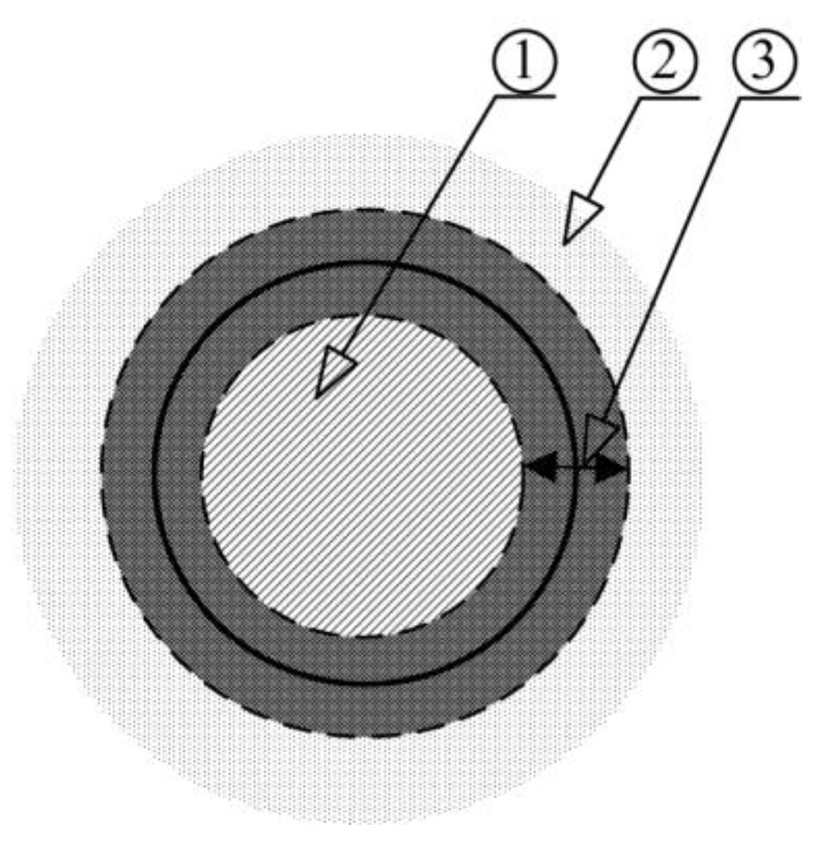
- The chemical affinity of limestone aggregate and cement paste;
- The surface roughness of limestone grains.
- Low absorbability;
- Good frost resistance;
- Resistance to polishing and surface abrasion.
- The production of bituminous mixtures;
- Road foundations for the binding and levelling of wearing courses;
- Renovations and repairs of roads;
- Hardening the surface of alleys and garden paths.
3. Experimental Section
3.1. The Purpose and the Scope of the Research
- Critical stress intensity factor—;
- Critical crack tip-opening displacement—.
- Compressive strength—fcm;
- Splitting tensile strength—fctm.
3.2. Materials
3.2.1. Aggregates
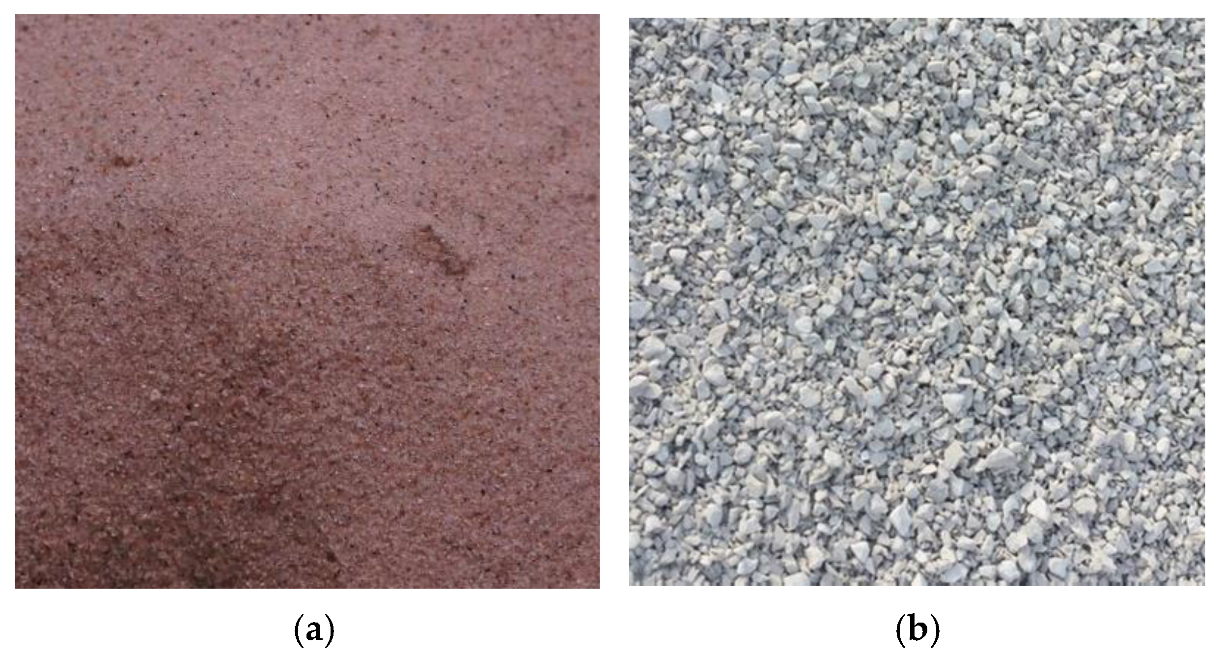
- Natural pit sand with 2.0 mm maximum size, from Markuszów deposit—used as fine aggregate;
- Natural broken limestone, often used in the building industry, with 8.0 mm or 16.0 maximum size, from Trzuskawica deposit—used as coarse aggregate.
3.2.2. Binder
3.2.3. Water
3.2.4. Admixture
3.3. Mixture Design, Specimen Preparation and Curing Procedure
- Cubes for evaluating mechanical parameters fcm and fctm;
- Beams with one initial crack to assess the fracture toughness parameters , and CTODc.
3.4. Test Procedures
3.4.1. Examinations of Mechanical Parameters
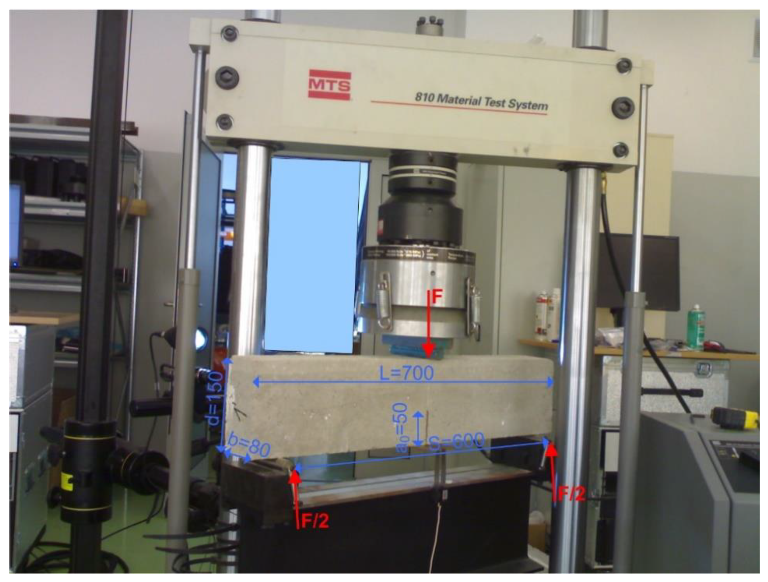
3.4.2. Fracture Toughness Investigations
- Maximum load obtained in the tests, marked in red (Fmax);
- Tangent in the first phase of the F–CMOD relationship, highlighted in blue (Ci);
- Tangent in the second phase of the F–CMOD relationship, highlighted in yellow (Cu).
4. Results and Discussion
4.1. Mechanical Parameters
4.2. Fracture Toughness
- About 3.0 kN for series L1 concrete, i.e., with a maximum grain size of up to 8 mm;
- Almost 5.0 kN for series L2 concrete, i.e., with a maximum grain size of up to 16 mm.
5. Summary and Conclusions
- 23% in the case of ;
- 28% in the case of .
- 15% in the case of fcm;
- 18% in the case of fctm.
- Concretes made of limestone aggregates with a maximum aggregate grain size up to 16 mm are characterized by increases in strength values fcm and fctm, of several percent to 20%, compared to concretes containing the same type of coarse aggregate with a smaller grain size of up to 8 mm (Table 9 and Table 10).
- Concretes with limestone aggregates with a maximum grain size of up to 16 mm behave like brittle materials during the ongoing destruction process. However, in concretes with a maximum grain size of up to 8 mm, signs of quasi-plasticity are visible during their destruction process (Table 11).
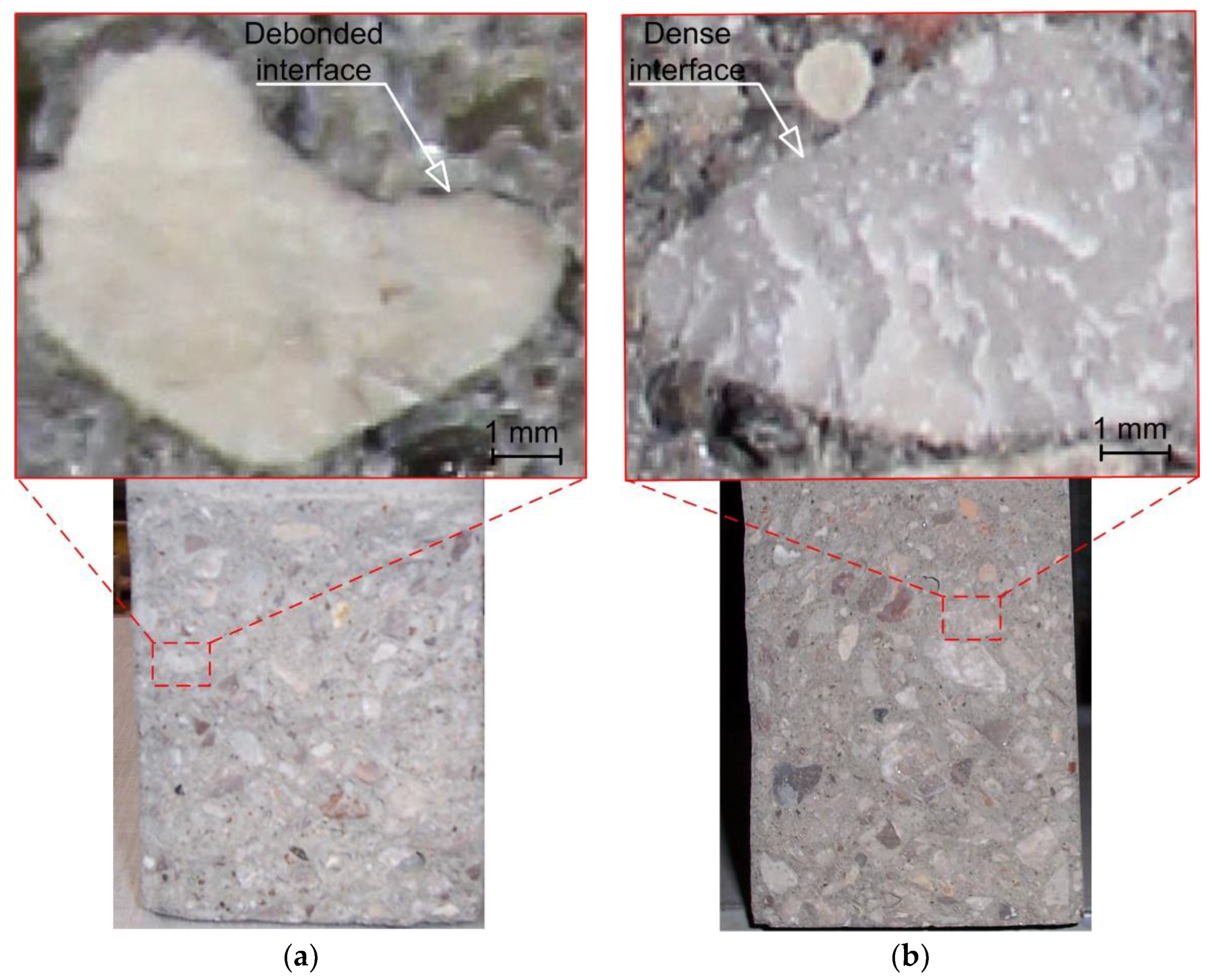
- Due to intensified feature for creating a diffusion zone in the ITZ area, larger grains of limestone aggregates are able to produce more compact contact points between coarse aggregate grains and the paste (Figure 4). This had a decisive impact on the obtained favorable strength parameters and fracture mechanics parameters in the L2 series concrete.
- The use of the research results presented in this study may be helpful in designing the composition of concrete mixtures with limestone aggregates with a focus on improving their fracture toughness. This, in turn, may contribute to obtaining a construction material with a reduced number of initial defects in the ITZ zone. Increases in mechanical parameters of concrete and an improvement of its fracture toughness will consequently lead to an increase in the reliability of concrete structures made of such materials.
Funding
Institutional Review Board Statement
Informed Consent Statement
Data Availability Statement
Conflicts of Interest
References
- Liu, F.; Zou, Y.; Wang, B.; Yuan, X. The Effect of Stray Current on Calcium Leaching of Cement-Based Materials. Materials 2022, 15, 2279. [Google Scholar] [CrossRef]
- Wardach, M.; Krentowski, J.R.; Mackiewicz, M. Evaluation of Precast Beam Deflections Resulting in Cracks in Curtain Walls. Eng. Fail. Anal. 2022, 140, 106568. [Google Scholar] [CrossRef]
- Golewski, G.L. The Specificity of Shaping and Execution of Monolithic Pocket Foundations (PF) in Hall Buildings. Buildings 2022, 12, 192. [Google Scholar] [CrossRef]
- Zhang, S.; Han, B.; Xie, H.; An, M.; Lyu, S. Brittleness of Concrete under Different Curing Conditions. Materials 2021, 14, 7865. [Google Scholar] [CrossRef]
- Yao, W.; Pang, J.; Liu, Y. An Experimental Study of Portland Cement and Superfine Cement Slurry Grouting in Loose Sand and Sandy Soil. Infrastructures 2018, 3, 9. [Google Scholar] [CrossRef] [Green Version]
- Kovacik, J.; Marsavina, L.; Linul, E. Poisson’s Ratio of Closed-Cell Aluminum Foams. Materials 2018, 11, 1904. [Google Scholar] [CrossRef] [Green Version]
- Zhang, P.; Wang, C.; Gao, Z.; Wang, F. A Review on Fracture Properties of Steel Fiber Reinforced Concrete. J. Build. Eng. 2023, 67, 105975. [Google Scholar] [CrossRef]
- Craciun, E.M. Energy Criteria for Crack Propagation in Prestresses Elastic Composites. Sol. Mech. Appl. 2008, 154, 193–237. [Google Scholar]
- Golewski, G.L. The Phenomenon of Cracking in Cement Concretes and Reinforced Concrete Structures: The Mechanism of Cracks Formation, Causes of Their Initiation, Types and Places of Occurrence, and Methods of Detection—A Review. Buildings 2023, 13, 765. [Google Scholar] [CrossRef]
- Kibriya, G.; Orosz, Á.; Botzheim, J.; Bagi, K. Calibration of Micromechanical Parameters for the Discrete Element Simulation of a Masonry Arch using Artificial Intelligence. Infrastructures 2023, 8, 64. [Google Scholar] [CrossRef]
- Vuoto, A.; Funari, M.F.; Lourenço, P.B. On the Use of the Digital Twin Concept for the Structural Integrity Protection of Architectural Heritage. Infrastructures 2023, 8, 86. [Google Scholar] [CrossRef]
- Golewski, G.L.; Szostak, B. Strength and Microstructure of Composites with Cement Matrixes Modified by Fly Ash and Active Seeds of C-S-H Phase. Struct. Eng. Mech. 2022, 82, 543–556. [Google Scholar]
- Craciun, E.M.; Carabineanu, A.; Peride, N. Antiplane Interface Crack in a Pre-Stressed Fiber-Reinforced Elastic Composite. Comp. Mater. Sci. 2008, 43, 184–189. [Google Scholar] [CrossRef]
- Fournari, R.; Ioannou, I. Correlations between the Properties of Crushed Fine Aggregates. Minerals 2019, 9, 86. [Google Scholar] [CrossRef] [Green Version]
- Gil, D.M.; Golewski, G.L. Potential of Siliceous Fly Ash and Silica Fume as a Substitute of Binder in Cementitious Concrete. E3S Web Conf. 2018, 49, 00030. [Google Scholar] [CrossRef] [Green Version]
- Golewski, G.L. Study of Strength and Microstructure of a New Sustainable Concrete Incorporating Pozzolanic Materials. Struct. Eng. Mech. 2023, 86, 431–441. [Google Scholar]
- Kong, Y.; Wang, P.; Liu, S.; Zhao, G.; Peng, Y. SEM Analysis of the Interfacial Transition Zone between Cement-Glass Powder Paste and Aggregate of Mortar under Microwave Curing. Materials 2016, 9, 733. [Google Scholar] [CrossRef] [Green Version]
- Golewski, G.L. Concrete Composites Based on Quaternary Blended Cements with a Reduced Width of Initial Microcracks. Appl. Sci. 2023, 13, 7338. [Google Scholar] [CrossRef]
- Imtiaz, T.; Ahmed, A.; Hossain, M.S.; Faysal, M. Microstructure Analysis and Strength Characterization of Recycled Base and Sub-Base Materials Using Scanning Electron Microscope. Infrastructures 2020, 5, 70. [Google Scholar] [CrossRef]
- Hashemmoniri, S.; Fatemi, A. Optimization of Lightweight Foamed Concrete Using Fly Ash Based on Mechanical Properties. Inn. Infr. Sol. 2023, 8, 59. [Google Scholar] [CrossRef]
- Golewski, G.L. Studies of Natural Radioactivity of Concrete with Siliceous Fly Ash Addition. Cem. Wapno Beton 2015, 2, 106–114. [Google Scholar]
- Wang, L.; Zhang, P.; Golewski, G.L.; Guan, J. Editorial: Fabrication and Properties of Concrete Containing Industrial Waste. Front. Mater. 2023, 10, 1169715. [Google Scholar]
- Golewski, G.L. The Effect of the Addition of Coal Fly Ash (CFA) on the Control of Water Movement within the Structure of the Concrete. Materials 2023, 16, 5218. [Google Scholar] [CrossRef]
- Wei, J.; Liu, J.; Khayat, K.H.; Long, W.-J. Synergistic Effect of HEDP.4Na and Different Induced Pouring Angles on Mechanical Properties of Fiber-Reinforced Alkali-Activated Slag Composites. Fibers 2023, 11, 23. [Google Scholar] [CrossRef]
- Golewski, G.L.; Sadowski, T. Macroscopic Evaluation of Fracture Processes in Fly Ash Concrete. Solid State Phenom. 2016, 254, 188–193. [Google Scholar] [CrossRef]
- Reis, J.M.L.; Chianelli-Junior, R.; Cardoso, J.L.; Marinho, F.J.V. Effect of Recycled PET in the Fracture Mechanics of Polymer Mortar. Constr. Build. Mater. 2011, 25, 2799–2804. [Google Scholar] [CrossRef] [Green Version]
- Li, X.; Zhang, Q. Influence Behavior of Phosphorus Slag and Fly Ash on the Interface Transition Zone in Concrete Prepared by Cement-Red Mud. J. Build. Eng. 2021, 49, 104017. [Google Scholar] [CrossRef]
- Golewski, G.L.; Sadowski, T. A Study on Mode III Fracture Toughness in Young and Mature Concrete with Fly Ash Additive. Solid State Phenom. 2016, 254, 120–125. [Google Scholar] [CrossRef]
- Prokopski, G. Effect of Coarse Aggrregate Quantity on Fracture Toughness of Concretes. J. Mater. Sci. 1993, 28, 5717–5721. [Google Scholar] [CrossRef]
- Hordijk, D.A.; Wolsink, G.M.; de Vries, J. Fracture and Fatigue Behaviour of a High Strength Limestone Concrete as a Compared to Gravel Concrete. Heron 1995, 40, 125–146. [Google Scholar]
- Golewski, G.; Sadowski, T. Fracture Toughness at Shear (Mode II) of Concretes Made of Natural and Broken Aggregates. Brittle Matrix Compos. 2006, 8, 537–546. [Google Scholar]
- Prokopski, G.; Halbiniak, J. Interfacial Transition Zone in Cementitious Materials. Cem. Concr. Res. 2000, 30, 579–583. [Google Scholar] [CrossRef]
- Schmidt, R.A. Fracture-Toughness Testing of Limestone. Exp. Mech. 1976, 16, 161–167. [Google Scholar] [CrossRef]
- Iha, A.K. Dynamic Fracture Toughness Test of Limestone. J. Geol. Res. Eng. 2020, 8, 184–196. [Google Scholar]
- Qi, J.; Jiang, L.; Zhu, M.; Mu, C.; Li, R. Experimental Study on the Effect of Limestone Powder Content on the Dynamic and Static Mechanical Properties of Seawater Coral Aggregate Concrete (SCAC). Materials 2023, 16, 3381. [Google Scholar] [CrossRef]
- Helmer, G.S.; Sulem, J.; Ghabezloo, S.; Rohmer, J.; Hild, F. Experimental Evaluation of the Fracture Toughness on a Limestone. In Proceedings of the ISRM Regional Symposium—EUROCK 2014, Vigo, Spain, 26–28 May 2014. [Google Scholar]
- Singh, R.N.; Sun, G. A Numerical and Experimental Investigation for Determining Fracture Toughness of Welsh Limestone. Min. Sci. Technol. 1990, 10, 61–70. [Google Scholar] [CrossRef]
- Menadi, B.; Kenai, S.; Khatib, J.M. Fracture Behaviour of Concrete Containing Limestone Fines. Proc. Inst. Civ. Eng.–Constr. Mater. 2014, 167, 162–170. [Google Scholar] [CrossRef]
- Prokopski, G.; Halbiniak, J.; Langier, B. The Examination of the Fracture Toughness of Concretes with Diverse Structure. J. Mater. Sci. 1998, 33, 1819–1825. [Google Scholar] [CrossRef]
- Golewski, G.L. An Analysis of Fracture Toughness in Concrete with Fly Ash Addition, Considering All Models of Cracking. IOP Conf. Ser. Mater. Sci. Eng. 2018, 416, 012029. [Google Scholar] [CrossRef] [Green Version]
- Bochenek, A.; Prokopski, G.B. The Investigation of Aggregate Grain Size Effect on Fracture Toughness of Ordinary Concrete Structures. Int. J. Fract. 1989, 41, 197–205. [Google Scholar] [CrossRef]
- Golewski, G.L.; Sadowski, T. Experimental Investigation and Numerical Modelling Fracture Processes in Fly Ash Concrete at Early Age. Solid State Phenom. 2012, 188, 158–163. [Google Scholar] [CrossRef]
- Carlos, A.; Masumi, I.; Hiroaki, M.; Maki, M.; Takahisa, O. The Effects of Limestone Aggregate on Concrete Properties. Constr. Build. Mater. 2010, 24, 2363–2368. [Google Scholar]
- Neville, A.M. Properties of Concrete; Pearson Education Limited: Harlow, UK, 2011. [Google Scholar]
- Aghajanian, A.; Cimentada, A.; Fayyaz, M.; Brand, A.S.; Thomasa, C. ITZ Microanalysis of Cement-based Building Materials with Incorporation of Siderurgical Aggregates. J. Build. Eng. 2023, 67, 106008. [Google Scholar] [CrossRef]
- Golewski, G.L. Fracture Performance of Cementitious Composites Based on Quaternary Blended Cements. Materials 2022, 15, 6023. [Google Scholar] [CrossRef]
- Van Mier, J.G.M. Fracture Processes of Concrete: Assessment of Material Parameters for Fracture Models; CRC Press: Boca Raton, FL, USA; New York, NY, USA; London, UK; Tokyo, Japan, 2000. [Google Scholar]
- Sun, Z.; Xiong, J.; Cao, S.; Zhu, J.; Jia, X.; Hu, Z.; Liu, K. Effect of Different Fine Aggregate Characteristics on Fracture Toughness and Microstructure of Sand Concrete. Materials 2023, 16, 2080. [Google Scholar] [CrossRef]
- Golewski, G.L. The Role of Pozzolanic Aactivity of Siliceous Fly Ash in the Formation of the Structure of Sustainable Cementitious Composites. Sustain. Chem. 2022, 3, 520–534. [Google Scholar] [CrossRef]
- Ghafoori, N.; Spitek, R.; Najimi, M. Influence of Limestone Size and Content on Transport Properties of Self-Consolidating Concrete. Constr. Build. Mater. 2016, 127, 588–595. [Google Scholar] [CrossRef]
- Lewicka, E.; Szlugaj, J.; Burkowicz, A.; Galos, K. Sources and Markets of Limestone Flour in Poland. Resources 2020, 9, 118. [Google Scholar] [CrossRef]
- Golewski, G.L. Combined Effect of Coal Fly Ash (CFA) and Nanosilica (Ns) on the Strength Parameters and Microstructural Properties of Eco-Friendly Concrete. Energies 2023, 16, 452. [Google Scholar] [CrossRef]
- Xie, T.; Yang, G.; Zhao, X.; Xu, J.; Fang, C. A Unified Model for Predicting the Compressive Strength of Recycled Aggregate Concrete Containing Supplementary Cementitious Materials. J. Clean. Prod. 2020, 251, 119752. [Google Scholar] [CrossRef]
- Jwaida, Z.; Dulaimi, A.; Mashaan, N.; Othuman Mydin, M.A. Geopolymers: The Green Alternative to Traditional Materials for Engineering Applications. Infrastructures 2023, 8, 98. [Google Scholar] [CrossRef]
- Golewski, G.L. Mechanical Properties and Brittleness of Concrete Made by Combined Fly Ash, Silica Fume and Nanosilica with ordinary Portland cement. AIMS Mater. Sci. 2023, 10, 390–404. [Google Scholar] [CrossRef]
- DIN 4226-1:2001-07; Aggregates for Concrete and Mortar—Part 1: Normal and Heavy-Weight Aggregates. German Standards Institution: Essen, Germany, 2001.
- EN 197-1:2011; Cement–Part 1: Composition, Specifications and Conformity Criteria for Common Cements. NSAI Standard: Dublin, Ireland, 2011.
- EN 1008:2002; Mixing Water for Concrete—Specification for Sampling, Testing and Assessing the Suitability of Water, Including Water Recovered from Processes in the Concrete Industry, as Mixing Water for Concrete. British Standards Institution (BSI): London, UK, 2002.
- EN 12390-2:2019; Testing Hardened Concrete–Part 2: Making and Curing Specimens for Strength Tests. British Standards Institution (BSI): London, UK, 2019.
- EN 12390-3: 2011+AC; Testing Hardened Concrete–Part 3: Compressive Strength of Test Specimens. British Standards Institution (BSI): London, UK, 2012.
- EN 12390-6: 2009; Testing Hardened Concrete–Part 6: Tensile Splitting Strenght of Test Specimens. British Standards Institution (BSI): London, UK, 2009.
- Shah, S.P. Determination of fracture parameters ( and CTODc) of plain concrete using three-point bend tests, RILEM Draft Recommendations, TC 89-FMT Fracture Mechanics of Concrete Test Methods. Mater. Struct. 1990, 23, 457–460. [Google Scholar] [CrossRef]
- Hu, H.; Huang, Y.; Zhao, L.; Xiong, M. Shaking Table Tests on Slope Reinforced by Anchored Piles under Random Earthquake Ground Motions. Acta Geot. 2022, 17, 4113–4130. [Google Scholar] [CrossRef]
- Bao, Y.; Hu, H.; Gan, G. Seismic Response Analysis of Slope Reinforced by Pile-Anchor Structures under Near-Fault Pulse-like Ground Motions. Soil Dynam. Earth. Eng. 2023, 164, 107576. [Google Scholar] [CrossRef]
- Golewski, G.L. Comparative Measurements of Fracture Toughness Combined with Visual Analysis of Cracks Propagation Using the DIC Technique of Concretes Based on Cement Matrix with a Highly Diversified Composition. Theor. Appl. Fract. Mech. 2022, 121, 103553. [Google Scholar] [CrossRef]
- Golewski, G.L. An Extensive Investigations on Fracture Parameters of Concretes Based on Quaternary Binders (QBC) by Means of the DIC Technique. Constr. Build. Mater. 2022, 351, 128823. [Google Scholar] [CrossRef]
- Pena-Caballero, C.; Kim, D.; Gonzalez, A.; Castellanos, O.; Cantu, A.; Ho, J. Real-Time Road Hazard Information System. Infrastructures 2020, 5, 75. [Google Scholar] [CrossRef]
- Wu, J.; Yang, J.; Zhang, R.; Jin, L.; Du, X. Fatigue Life Estimating for Chloride Attacked RC Beams Using S-N Curve Combined with Mesoscale Simulation of Chloride Ingress. Int. J. Fat. 2022, 158, 106751. [Google Scholar] [CrossRef]
- Perdikaris, P.C.; Romeo, A. Size Effect on Fracture Energy of Concrete and Stability Issues in Three-Point Bending Fracture Toughness Testing. ACI Mater. J. 1995, 92, 483–496. [Google Scholar]
- Golewski, G.L. Changes in the Fracture Toughness under Mode II Loading of Low Calcium Fly Ash (LCFA) Concrete Depending on Ages. Materials 2020, 13, 5241. [Google Scholar] [CrossRef] [PubMed]
- Zhang, B.; Zhu, H.; Lu, F. Fracture Properties of Slag-Based Alkali-Activated Seawater Coral Aggregate. Theor. Appl. Fract. Mech. 2019, 115, 103071. [Google Scholar] [CrossRef]
- Peride, N.; Carabineanu, A.; Craciun, E.M. Mathematical Modelling of the Interface Crack Propagation in a Pre-Stressed Fiber Reinforced Elastic Composite. Comp. Mater. Sci. 2009, 45, 684–692. [Google Scholar] [CrossRef]
- Linul, E.; Marsavina, L.; Valean, C.; Banica, R. Static and dynamic mode I fracture toughness of rigid PUR foams under room and cryogenic temperatures. Eng. Fract. Mech. 2020, 225, 106274. [Google Scholar] [CrossRef]
- Kathirvel, P.; Murali, G. Effect of using Available GGBFS, Silica Fume, Quartz Powder and Steel Fibres on the Fracture Behavior of Sustainable Reactive Powder Concrete. Constr. Build. Mater. 2023, 375, 130997. [Google Scholar] [CrossRef]


| Property | Unit | Aggregate Type | |
|---|---|---|---|
| Fine Aggregate (Sand) | Coarse Aggregate (Limestone) | ||
| Specific Density | (g/cm3) | 2.60 | 2.85 |
| Bulk Density | (g/cm3) | 2.20 | 2.70 |
| Compressive Strength | (MPa) | 33 | 100 |
| Modulus of Elasticity | (102 MPa) | 330 | 450 |
| Absorption | (%) | 0.5 | 0.3 |
| Fraction (mm) | Content of Aggregate Fraction (%) | ||
|---|---|---|---|
| Sand | Coarse Aggregate, L1 | Mix | |
| 0–0.125 | 2.7 | 0.9 | 1.6 |
| 0.125–0.25 | 14.9 | 0.6 | 5.6 |
| 0.25–0.5 | 42.7 | 0.5 | 15.5 |
| 0.5–1.0 | 31.4 | 1.3 | 12.1 |
| 1.0–2.0 | 3.9 | 6.3 | 5.5 |
| 2.0–4.0 | 4.4 | 19.3 | 14.1 |
| 4.0–8.0 | - | 62.2 | 40.1 |
| 8.0–16.0 | - | 8.9 | 5.5 |
| Sand point | 95.6 | 9.6 | 40.3 |
| Fraction (mm) | Sand | Coarse Aggregate | Mix | |
|---|---|---|---|---|
| L2-1 | L2-2 | |||
| 0–0.125 | 2.5 | 2.1 | 0.2 | 2.1 |
| 0.125–0.25 | 16.2 | 1.5 | 0.4 | 5.1 |
| 0.25–0.5 | 42.2 | 0.6 | - | 11.3 |
| 0.5–1.0 | 31.1 | 1.2 | - | 10.7 |
| 1.0–2.0 | 5.2 | 3.8 | - | 4.1 |
| 2.0–4.0 | 2.8 | 17.5 | - | 8.6 |
| 4.0–8.0 | - | 66.8 | 10.8 | 33.8 |
| 8.0–16.0 | - | 6.5 | 88.6 | 24.2 |
| Sand point | 97.2 | 9.2 | 0.6 | 33.3 |
| Material\Constituent | SiO2 | Al2O3 | CaO | MgO | SO3 | Fe2O3 | K2O | P2O5 | TiO2 | Ag2O |
|---|---|---|---|---|---|---|---|---|---|---|
| OPC | 15.00 | 2.78 | 71.06 | 1.38 | 4.56 | 2.72 | 1.21 | - | - | - |
| Material\Phase | C3S | C2S | C3A | C4AF | CaSO4 (Gypsum) |
|---|---|---|---|---|---|
| OPC | 60.69 | 15.82 | 9.24 | 7.28 | 5.10 |
| Analyzed Parameter | ||||||
|---|---|---|---|---|---|---|
| Specific Gravity (g/cm3) | Specific Surface Area (m2/g) | Average Particle Diameter (μm) | Setting Time (min) | Compressive Strength (MPa) | ||
| Initial | Final | 2 Days | 28 Days | |||
| 3.11 | 0.33 | 40.0 | 207 | 298 | 23.3 | 50.0 |
| Mix | OPC | W | P | Sand | Limestone: L1, 2–8 mm | Limestone: L2-1, 2–8 mm + L2-2, 8–16 mm |
|---|---|---|---|---|---|---|
| L1 | 352 | 141 | 2 | 676 | 1207 | - |
| L2 | 352 | 141 | 2 | 676 | - | 1207 |
| Parameter Type | Parameter Characteristics |
|---|---|
| Testing machine used in the study | Walter + Bai AG hydraulic servo testing machine |
| The shape of the specimens | Cube |
| Specimens’ dimensions | 150 × 150 × 150 mm |
| Studies that used specimens |
|
| Number of specimens | 6 specimens for each test and each series of concrete |
| Type of specimen load | Static |
| Standards used in the studies |
| Mix | (MPa) | δ (MPa) | ν (%) | , Max. (MPa) | , Min. (MPa) |
|---|---|---|---|---|---|
| L1 | 39.17 | 1.09 | 2.8 | 42.15 | 37.88 |
| L2 | 45.06 | 2.57 | 5.7 | 47.18 | 43.62 |
| Mix | (MPa) | δ (MPa) | ν (%) | , Max. (MPa) | , Min. (MPa) |
|---|---|---|---|---|---|
| L1 | 2.57 | 0.15 | 5.7 | 2.81 | 2.25 |
| L2 | 3.03 | 0.2 | 6.2 | 3.23 | 2.87 |
| Mix | Typical F–CMOD Curve |
|---|---|
| L1 | 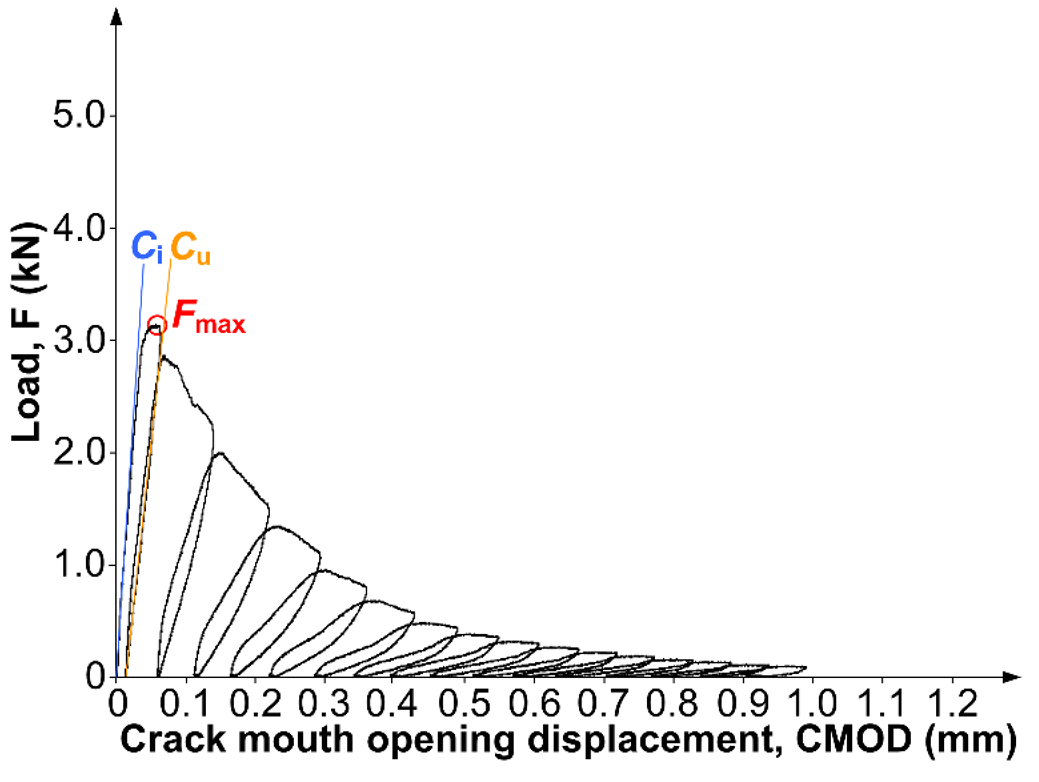 |
| L2 | 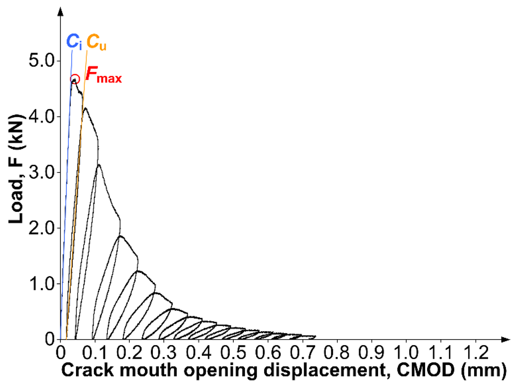 |
| Mix | (MN/m3/2) | δ (MN/m3/2) | ν | , Max. (MN/m3/2) | , Min. (MN/m3/2) |
|---|---|---|---|---|---|
| L1 | 0.99 | 0.13 | 8.98 | 1.28 | 0.76 |
| L2 | 1.22 | 0.18 | 7.08 | 1.38 | 1.06 |
| Mix | (m10−6) | δ (MPa) | ν | , Max. (m10−6) | , Min. (m10−6) |
|---|---|---|---|---|---|
| L1 | 10.02 | 1.28 | 8.76 | 13.16 | 8.45 |
| L2 | 12.87 | 3.29 | 7.25 | 15.13 | 10.22 |
Disclaimer/Publisher’s Note: The statements, opinions and data contained in all publications are solely those of the individual author(s) and contributor(s) and not of MDPI and/or the editor(s). MDPI and/or the editor(s) disclaim responsibility for any injury to people or property resulting from any ideas, methods, instructions or products referred to in the content. |
© 2023 by the author. Licensee MDPI, Basel, Switzerland. This article is an open access article distributed under the terms and conditions of the Creative Commons Attribution (CC BY) license (https://creativecommons.org/licenses/by/4.0/).
Share and Cite
Golewski, G.L. Effect of Coarse Aggregate Grading on Mechanical Parameters and Fracture Toughness of Limestone Concrete. Infrastructures 2023, 8, 117. https://doi.org/10.3390/infrastructures8080117
Golewski GL. Effect of Coarse Aggregate Grading on Mechanical Parameters and Fracture Toughness of Limestone Concrete. Infrastructures. 2023; 8(8):117. https://doi.org/10.3390/infrastructures8080117
Chicago/Turabian StyleGolewski, Grzegorz Ludwik. 2023. "Effect of Coarse Aggregate Grading on Mechanical Parameters and Fracture Toughness of Limestone Concrete" Infrastructures 8, no. 8: 117. https://doi.org/10.3390/infrastructures8080117
APA StyleGolewski, G. L. (2023). Effect of Coarse Aggregate Grading on Mechanical Parameters and Fracture Toughness of Limestone Concrete. Infrastructures, 8(8), 117. https://doi.org/10.3390/infrastructures8080117