
Influence of Patching on the Shear Failure of Reinforced Concrete Beam without Stirrup


Abstract
:1. Introduction
2. Materials and Methods
2.1. Materials
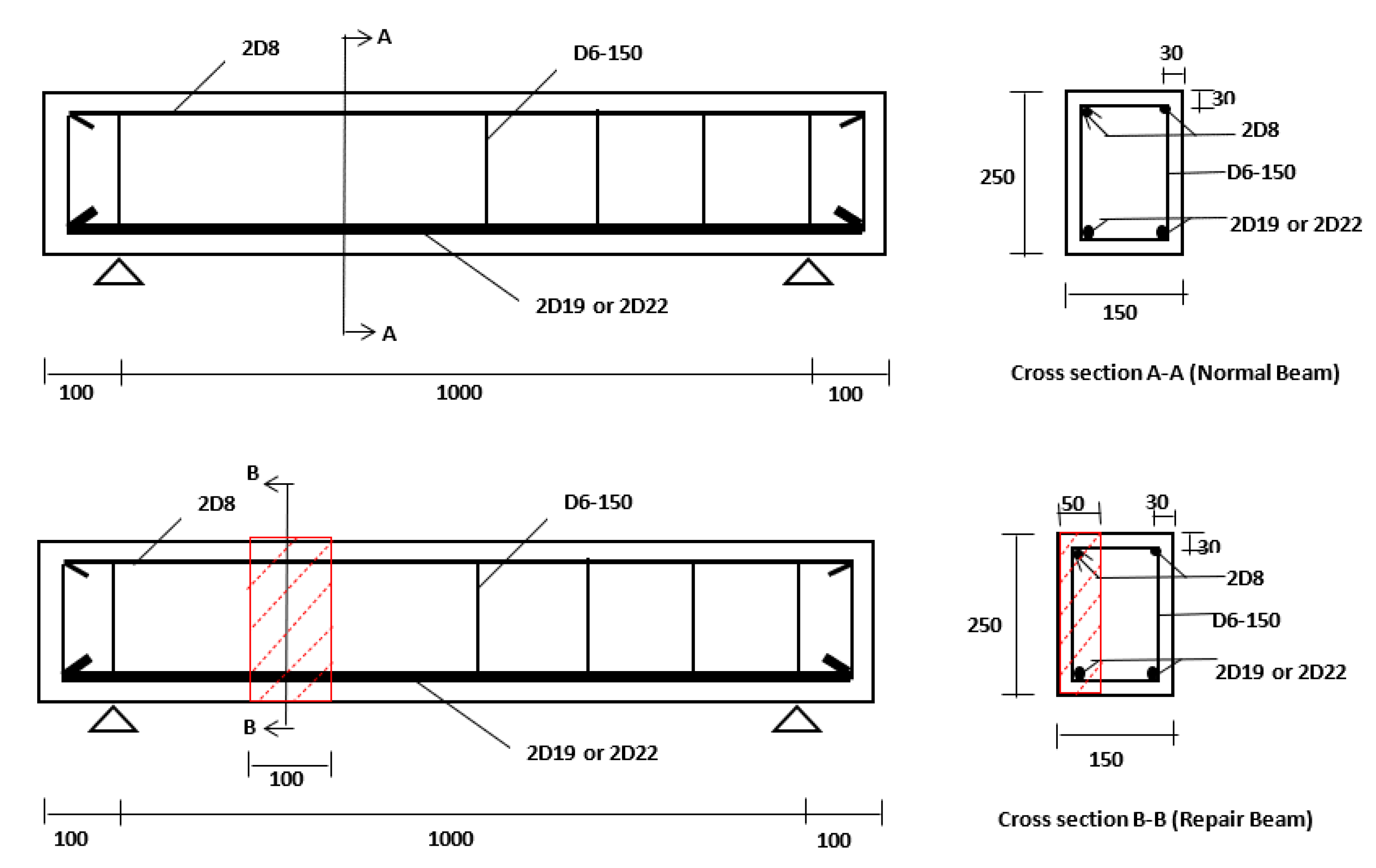
2.2. Beam Specimens
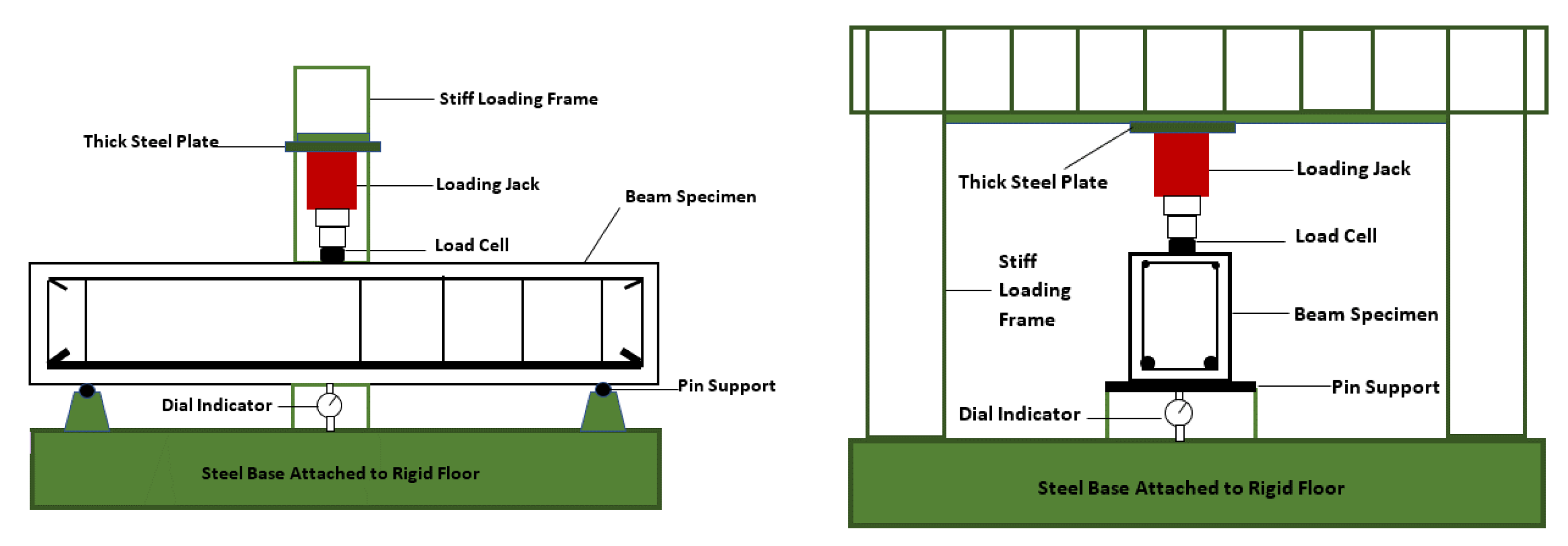
2.3. Testing Beam Specimens
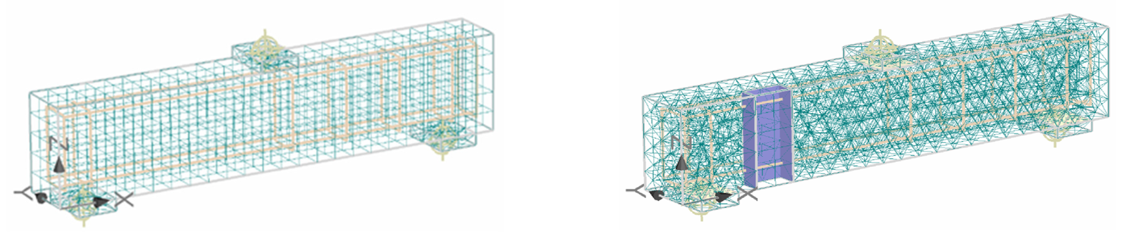
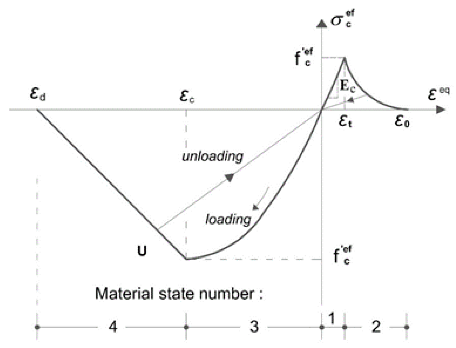
2.4. Numerical Modelling
3. Results and Discussion
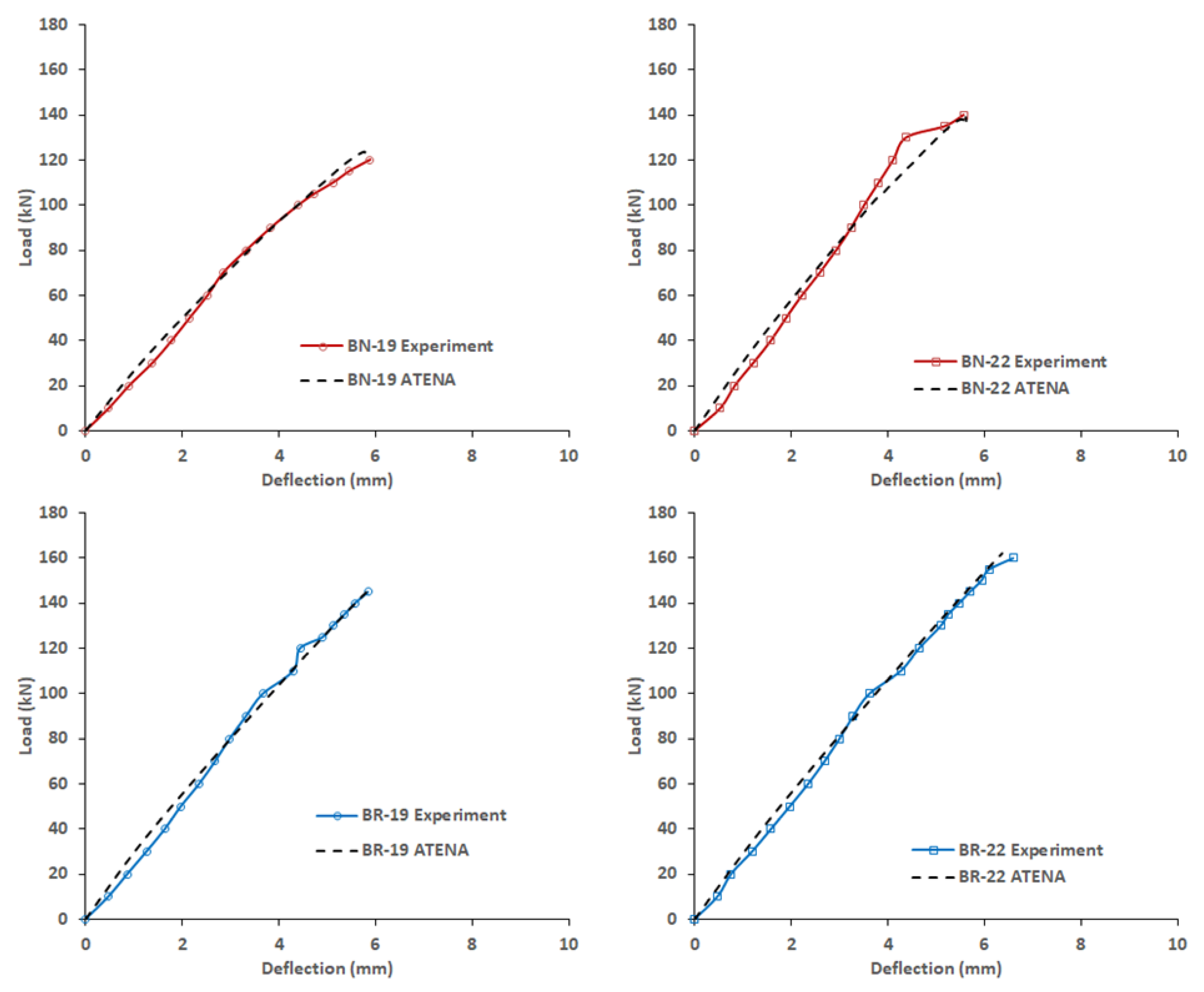
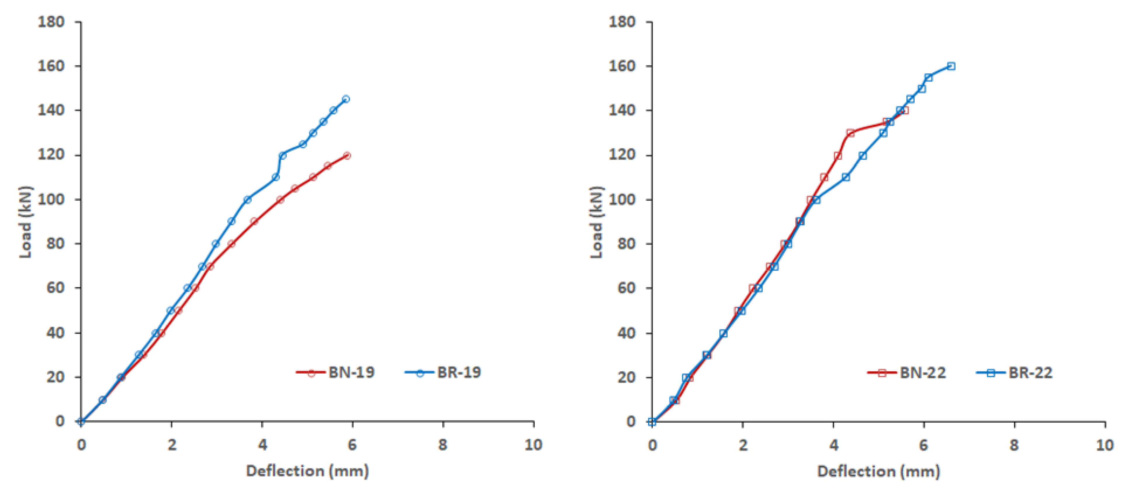
3.1. Load-Deflection Behaviour
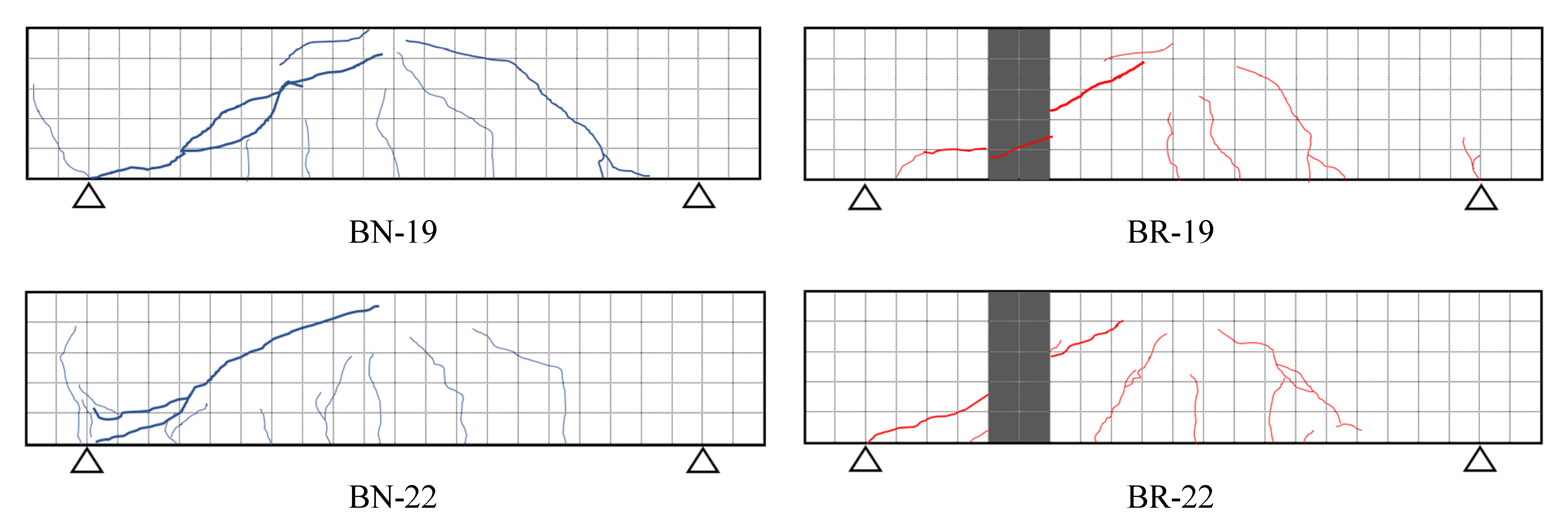
3.2. Shear Cracking Failure
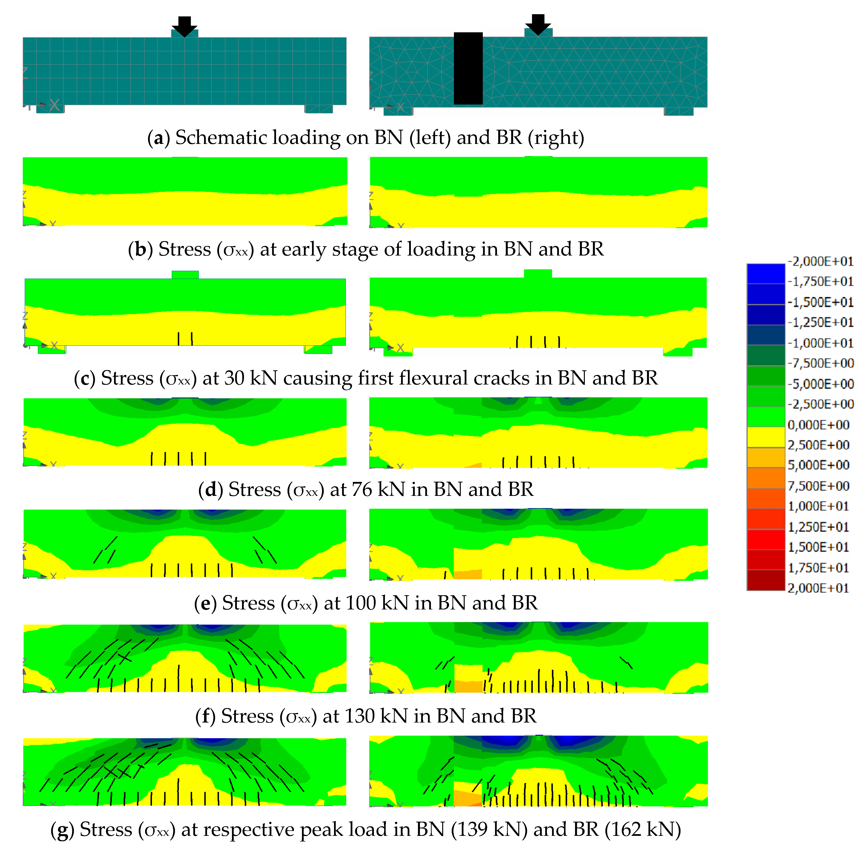
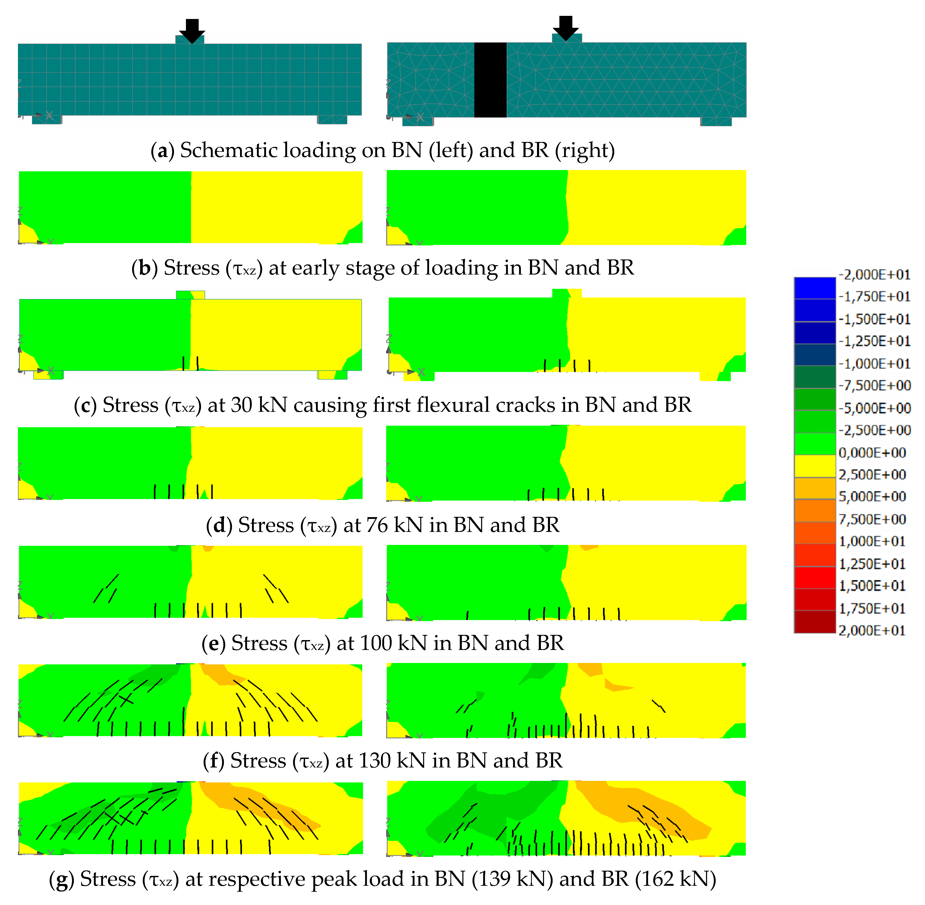
3.3. Stress Distribution in Concrete Beam
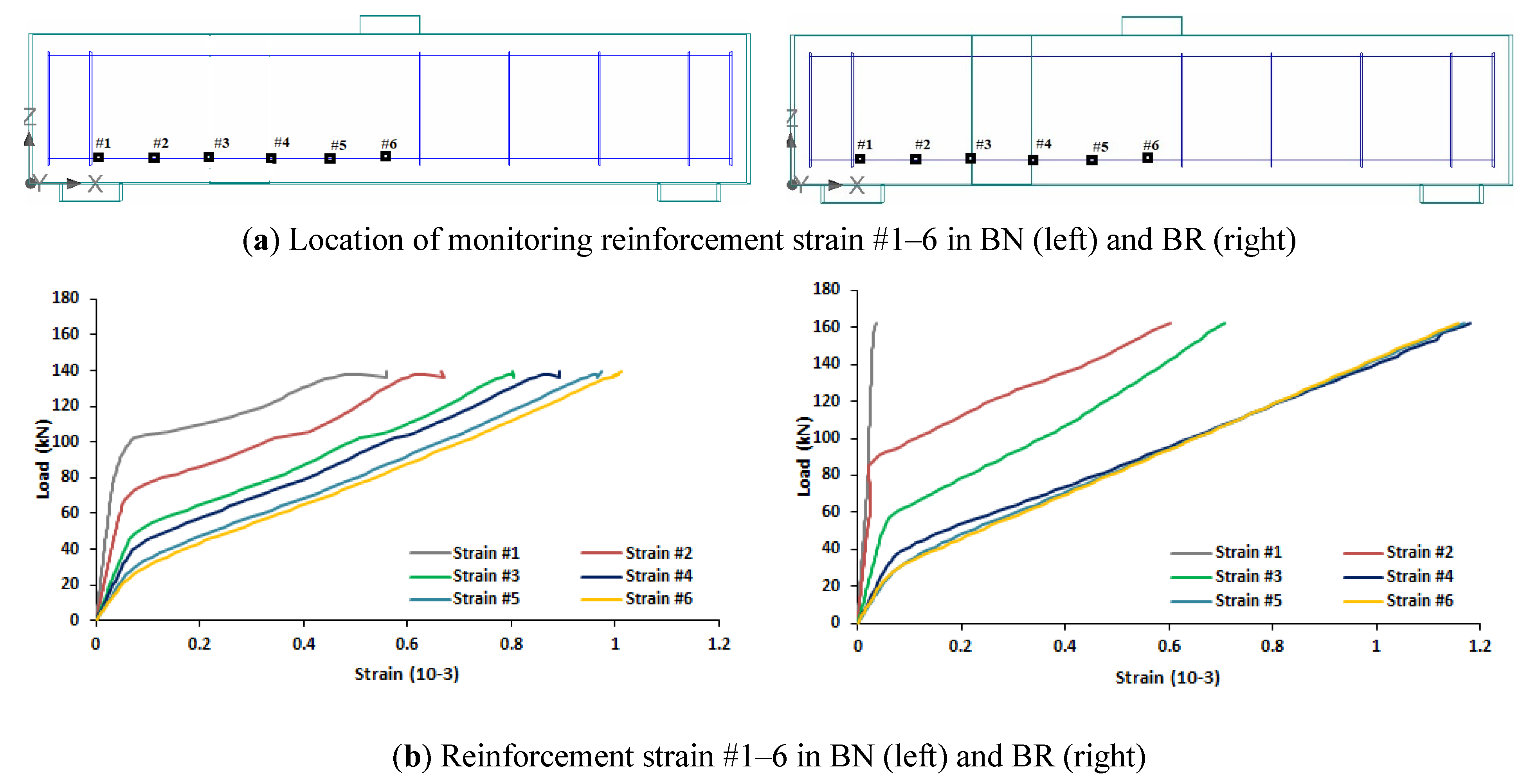
3.4. Reinforcement Strain
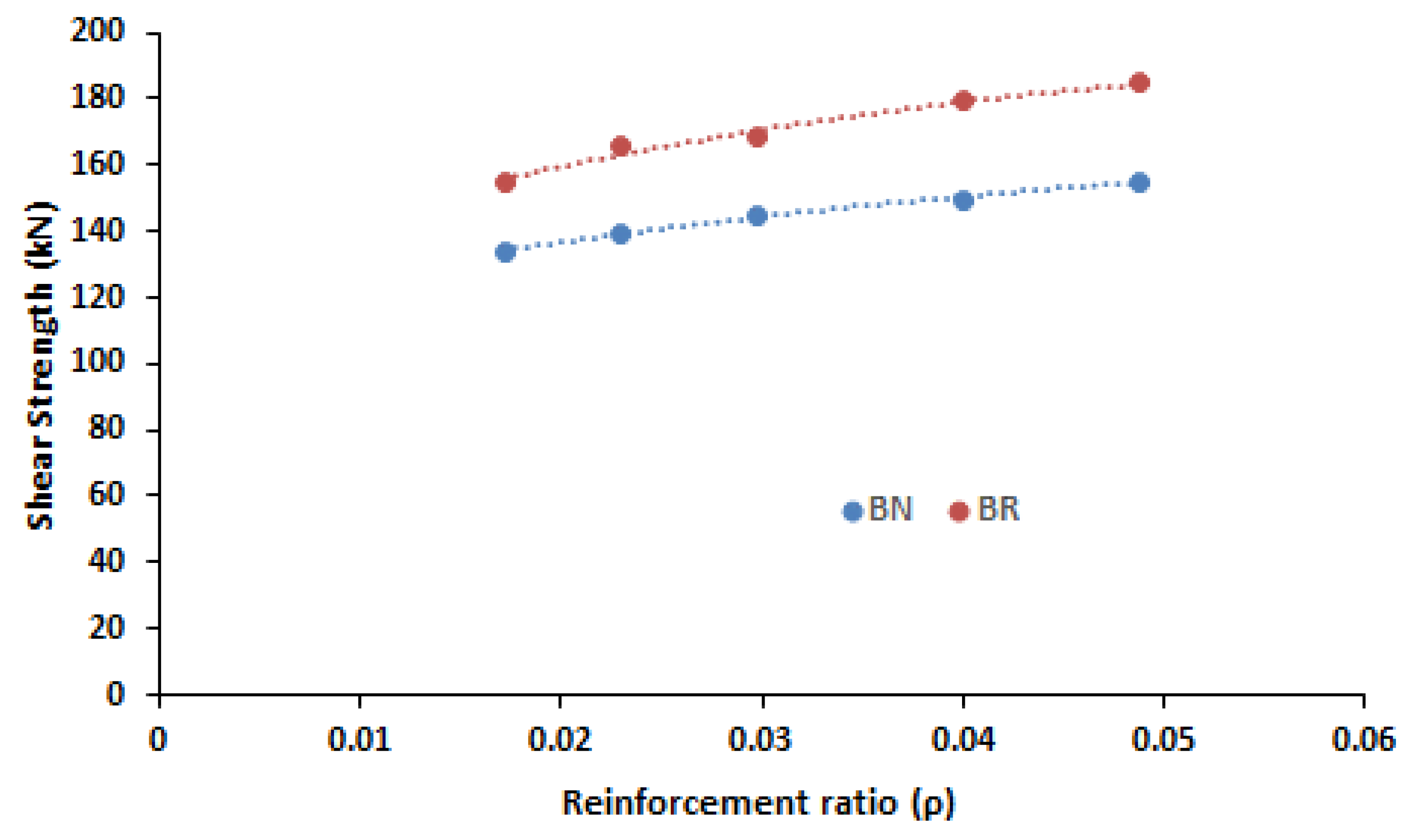
3.5. Shear Strength
4. Conclusions
- It causes the first diagonal crack appearing at a higher load compared to that of normal beam.
- The high tensile strength of UPR is beneficial to hamper the propagation of the diagonal cracks.
- It alters the stress distribution in such a way to cause the stresses in the span between support and UPR mortar decrease. On the other hand, the stresses in the span between UPR mortar and loading point increase.
- UPR mortar can increase the shear strength of the reinforced concrete beam about 15–20% at a variety of reinforcement ratios.
Author Contributions
Funding
Data Availability Statement
Acknowledgments
Conflicts of Interest
References
- ACI Committee. ACI Committee 318, “Building Code Requirements for Structural Concrete (ACI 318-14)”; ACI Committee: Farmington Hills, MI, USA, 2019. [Google Scholar]
- Badan Standarisasi Nasional. SNI 03-2847, “Persyaratan Beton Struktural Untuk Bangunan Gedung”; Badan Standarisasi Nasional: Jakarta, Indonesia, 2019; pp. 1–695.
- Kristiawan, S.; Supriyadi, A.; Sangadji, S.; Wicaksono, H.B. Shear failure of patched reinforced concrete beam without web reinforcements. Key Eng. Mater. 2017, 737, 441–447. [Google Scholar] [CrossRef]
- Belarbi, A.; Bae, S.W.; Brancaccio, A. Behavior of full-scale RC T-beams strengthened in shear with externally bonded FRP sheets. Constr. Build. Mater. 2012, 32, 27–40. [Google Scholar] [CrossRef]
- Shahbazpanahi, S.; Ali, A.A.A.; Kamgar, A.; Farzadnia, N. Fracture mechanic modeling of fiber reinforced polymer shear-strengthened reinforced concrete beam. Compos. Part B Eng. 2015, 68, 113–120. [Google Scholar] [CrossRef]
- Alam, M.A.; Al Riyami, K. Shear strengthening of reinforced concrete beam using natural fibre reinforced polymer laminates. Constr. Build. Mater. 2018, 162, 683–696. [Google Scholar] [CrossRef]
- Nguyen-Minh, L.; Rovňák, M. Size effect in uncracked and pre-cracked reinforced concrete beams shear-strengthened with composite jackets. Compos. Part B Eng. 2015, 78, 361–376. [Google Scholar] [CrossRef]
- Contamine, R.; Larbi, A.S.; Hamelin, P. Identifying the contributing mechanisms of textile reinforced concrete (TRC) in the case of shear repairing damaged and reinforced concrete beams. Eng. Struct. 2013, 46, 447–458. [Google Scholar] [CrossRef]
- Larbi, A.S.; Contamine, R.; Ferrier, E.; Hamelin, P. Shear strengthening of RC beams with textile reinforced concrete (TRC) plate. Constr. Build. Mater. 2010, 24, 1928–1936. [Google Scholar] [CrossRef]
- Täljsten, B.; Orosz, K.; Blanksvärd, T. Strengthening of concrete beams in shear with mineral based composites laboratory tests and theory. In Proceedings of the International Conference on FRP Composites in Civil Engineering, Miami, FL, USA, 13–15 December 2006; pp. 609–612. [Google Scholar]
- Ombres, L. Structural performances of reinforced concrete beams strengthened in shear with a cement based fiber composite material. Compos. Struct. 2015, 122, 316–329. [Google Scholar] [CrossRef]
- Triantafillou, T.C. Shear strengthening of reinforced concrete beams using epoxy-bonded FRP composites. ACI Struct. J. 1998, 95, 107–115. [Google Scholar]
- Matthews, S. CONREPNET: Performance-based approach to the remediation of reinforced concrete structures: Achieving durable repaired concrete structures. J. Build. Apprais. 2007, 3, 6–20. [Google Scholar] [CrossRef] [Green Version]
- Courard, L.; Garbacz, A. FAILURE OF CONCRETE REPAIR: HOW TO AVOID IT? In Proceedings of the 2nd International Symposium on Advances in Concrete through Science and Engineering, Quebec City, QC, Canada, 11–13 September 2006; pp. 167–191. [Google Scholar]
- Lukovic, M.; Ye, G.; van Breugel, K. Reliable concrete repair: A critical review. In Proceedings of the 14th International Conference on Structural Faults and Repair, Edinburgh, UK, 3–5 July 2012. [Google Scholar]
- Kiani, B.; Liang, R.Y.; Gross, J. Material selection for repair of structural concrete using VIKOR method. Case Stud. Constr. Mater. 2018, 8, 489–497. [Google Scholar] [CrossRef]
- Vaysburd, A.M.; Bissonnette, B.; von Fay, K.F. Compatibility Issues in Design and Implementation of Concrete Repairs and Overlays; US Department of the Interior, Bureau of Reclamation, Technical Service Center, Materials Engineering and Research Laboratory: Denver, CO, USA, 2014; Volume 385, pp. 1–136. [Google Scholar]
- Vaysburd, A.M. DURABILITY OF REPAIRED CONCRETE STRUCTURES—THE BATTLE FOR SURVIVAL. In Proceedings of the 2nd International Symposium on Advances in Concrete through Science and Engineering, Quebec City, QC, Canada, 11–13 September 2006; pp. 207–224. [Google Scholar]
- ACI Committee. ACI Committee 546, “Concrete Repair Guide (ACI 546R-04)”; ACI Committee: Montreal, QC, Canada, 2004. [Google Scholar]
- British Standard Institution. BS EN 1504-9:2008 Products and Systems for the Protection and Repair of Concrete Structures—Definitions, Requirements, Quality Control and Evaluation of Conformity—Part 9: General Principles for Use of Products and Systems; British Standard Institution: London, UK, 2008. [Google Scholar]
- Raupach, M.; Büttner, T. Concrete Repair to EN 1504; CRC Press Taylor & Francis Group: Boca Raton, FL, USA, 2014. [Google Scholar]
- Bhikshma, V.; Reddy, M.K.; Sunitha, K. Experimental study on rehabilitation of RC beams using epoxy resins. Asian J. Civ. Eng. 2010, 11, 533–542. [Google Scholar]
- Pattanaik, S.C. Structural strengthening of damaged RCC Structures with polymer modified concrete. In Proceedings of the Workshop 2009 on Rehabilitation and Retrofitting of Structures, Mumbai, India, 28–30 August 2009. [Google Scholar]
- Morgan, D.R. Compatibility of concrete repair materials and systems. Constr. Build. Mater. 1996, 10, 57–67. [Google Scholar] [CrossRef]
- Venkiteela, G.; Klein, M.; Najm, H.; Balaguru, P.N. Evaluation of the Compatibility of Repair Materials for Concrete Structures. Int. J. Concr. Struct. Mater. 2017, 11, 435–445. [Google Scholar] [CrossRef] [Green Version]
- Park, S.K.; Yang, D.S. Flexural behavior of reinforced concrete beams with cementitious repair materials. Mater. Struct. Constr. 2005, 38, 329–334. [Google Scholar] [CrossRef]
- Jumaat, M.Z.B.; Kabir, M.H.; Obaydullah, M. Structural performance of reinforced concrete beams repairing from spalling. Eur. J. Sci. Res. 2010, 45, 89–102. [Google Scholar]
- Mansour, W.; Tayeh, B.A. Shear Behaviour of RC Beams Strengthened by Various Ultrahigh Performance Fibre-Reinforced Concrete Systems. Adv. Civ. Eng. 2020, 2020. [Google Scholar] [CrossRef]
- Rafeeqi, S.; Lodi, S.; Wadalawala, Z. Behaviour of Reinforced Concrete Beams Strengthened in Shear. J. Ferrocem. 2005, 35, 479–489. [Google Scholar]
- Bahraq, A.A.; Al-Osta, M.A.; Ahmad, S.; Al-Zahrani, M.M.; Al-Dulaijan, S.O.; Rahman, M.K. Experimental and Numerical Investigation of Shear Behavior of RC Beams Strengthened by Ultra-High Performance Concrete. Int. J. Concr. Struct. Mater. 2019, 13, 1–19. [Google Scholar] [CrossRef]
- Collins, M.P.; Bentz, E.C.; Sherwood, E.G.; Xie, L. Adequate theory for the shear strength of reinforced concrete structures. In Proceedings of the Morley Symposium on Concrete Plasticity and Its Application, Cambridge, UK, 23 July 2007; pp. 75–94. [Google Scholar]
- Yang, Y.; van der Veen, C.; Hordijk, D.; de Boer, A. The shear capacity of reinforced concrete members with plain bars. In Proceedings of the 16th International Conference on Structural Fault and Repair, Edinburg, UK, 17–19 May 2016. [Google Scholar]
- Jeong, J.P.; Kim, W. Shear Resistant Mechanism into Base Components: Beam Action and Arch Action in Shear-Critical RC Members. Int. J. Concr. Struct. Mater. 2014, 8, 1–14. [Google Scholar] [CrossRef] [Green Version]
- Birgisson, S.R. Shear Resistance of Reinforced Concrete Beams without Stirrups; Reykjavik University: Reykjavik, Iceland, 2011. [Google Scholar]
- Nilson, A.; Darwin, D.; Dolan, C. Design of Concrete Structures, 14th ed.; McGraw-Hill: New York, NY, USA, 2010. [Google Scholar]
- MacGregor, J.G. Reinforced Concrete Mechanics & Design, 3rd ed.; Prentice Hall: Hoboken, NJ, USA, 1997. [Google Scholar]
- Budi, A.S.; Safitri, E.; Sangadji, S.; Kristiawan, S.A. Shear Strength of HVFA-SCC Beams without Stirrups. Buildings 2021, 11, 177. [Google Scholar] [CrossRef]
- Kristiawan, S.A.; Fitrianto, R.S. Comparison of shrinkage related properties of various patch repair materials. In Proceedings of the IOP Conference Series: Materials Science and Engineering, Bali, Indonesia, 19–20 March 2016; Volume 176, p. 012017. [Google Scholar]
- Kristiawan, S.A.; Utomo, V.P. Shrinkage cracking tendency of repair materials made from unsaturated polyester resin (UPR) mortar. In Proceedings of the 6th International Conference of Asian Concrete Federation, Seoul, Korea, 21–24 September 2014; pp. 1438–1441. [Google Scholar]
- Kristiawan, S.; Supriyadi, A.; Pradana, D.R.; Azhim, M.R.N. Flexural behaviour of one-way patched reinforced concrete (RC) slab under concentrated load. Asian J. Civ. Eng. 2018, 19, 157–164. [Google Scholar] [CrossRef]
- Kristiawan, S.A.; Prakoso, A.B. Flexural Behaviour of Patch-Repair Material Made from Unsaturated Polyester Resin (UPR)-Mortar. Mater. Sci. Forum 2016, 857, 426–430. [Google Scholar] [CrossRef]
- Kristiawan, S.; Supriyadi, A.; Sangadji, S.; Santosa, D. Cracking behaviour and its effect on the deflection of patched-reinforced concrete beam under flexural loading. In Proceedings of the MATEC Web of Conferences, Seoul, Korea, 22–25 August 2017; Volume 138. [Google Scholar]
- Stefanus, K.; Agus, S.; Ageng, B.P.; Siti, R. Mechanical properties of unsaturated polyester resin (UPR)—Mortar and its potential application to restore the strength and serviceability of patched reinforced concrete slab. Key Eng. Mater. 2017, 737, 560–566. [Google Scholar]
- Badan Standarisasi Nasional. SNI 7656:2012, "Tata Cara Pemilihan Campuran Untuk Beton Normal, Beton Berat Dan Beton Massa"; Badan Standarisasi Nasional: Jakarta, Indonesia, 2012.
- American Society of Testing and Materials. C579-01: Standard Test Methods for Compressive Strength of Chemical—Resistance Mortars, Grouts and Monolithic Surfacings and Polymer Concretes; ASTM Int.: West Conshohocken, PA, USA, 2013. [Google Scholar]


| Beam ID | Type of Beam | Tensile Reinforcement | Compressive Reinforcement | Stirrup at Half Shear Span | Concrete Compressive Strength 1 | UPR Mortar Compressive Strength 1 |
|---|---|---|---|---|---|---|
| BN-19 | Normal | 2D19 | 2D8 | D6-150 | 23.80 MPa | - |
| BR-19 | Repair | 2D19 | 2D8 | D6-150 | 23.80 MPa | 73.67 MPa |
| BN-22 | Normal | 2D22 | 2D8 | D6-150 | 25.29 MPa | - |
| BR-22 | Repair | 2D22 | 2D8 | D6-150 | 25.29 MPa | 73.67 MPa |
| Material | Average Compressive Strength (Cylinder) (MPa) | Characteristic Compressive Strength (Cylinder) (MPa) | Characteristic Compressive Strength (Cube) (MPa) | Tensile Strength (MPa) | Yield Stress (MPa) | Elastic Modulus (MPa) | Material Model |
|---|---|---|---|---|---|---|---|
| Concrete (BN-19 & BR-19) | 23.80 | 15.80 | 18.59 | 1.66 | 24,350 | 3D nonlinear cementitious material 2 | |
| Concrete (BN-22 & BR-22) | 25.29 | 17.29 | 20.34 | 1.78 | 25,640 | 3D nonlinear cementitious material 2 | |
| UPR-mortar | 73.6 | 21.5 | 12,500 | 3D nonlinear cementitious material 2 | |||
| Reinforcement D22 | 452 | 200,000 | Reinforcement-bilinear | ||||
| Reinforcement D19 | 475 | 200,000 | Reinforcement-bilinear | ||||
| Reinforcement D8 | 462 | 200,000 | Reinforcement-bilinear | ||||
| Reinforcement D6 | 395 | 200,000 | Reinforcement-bilinear | ||||
| Steel plate | 200,000 | 3D elastic isotropic | |||||
| Horizontal support | 10,000 | Linear spring | |||||
| Vertical support | Relative displacement −1, Stress 500,000 MPa Relative displacement +1, Stress 330–350 MPa | Nonlinear spring | |||||
Publisher’s Note: MDPI stays neutral with regard to jurisdictional claims in published maps and institutional affiliations. |
© 2021 by the authors. Licensee MDPI, Basel, Switzerland. This article is an open access article distributed under the terms and conditions of the Creative Commons Attribution (CC BY) license (https://creativecommons.org/licenses/by/4.0/).
Share and Cite
Kristiawan, S.A.; Saifullah, H.A.; Supriyadi, A. Influence of Patching on the Shear Failure of Reinforced Concrete Beam without Stirrup. Infrastructures 2021, 6, 97. https://doi.org/10.3390/infrastructures6070097
Kristiawan SA, Saifullah HA, Supriyadi A. Influence of Patching on the Shear Failure of Reinforced Concrete Beam without Stirrup. Infrastructures. 2021; 6(7):97. https://doi.org/10.3390/infrastructures6070097
Chicago/Turabian StyleKristiawan, Stefanus Adi, Halwan Alfisa Saifullah, and Agus Supriyadi. 2021. "Influence of Patching on the Shear Failure of Reinforced Concrete Beam without Stirrup" Infrastructures 6, no. 7: 97. https://doi.org/10.3390/infrastructures6070097
APA StyleKristiawan, S. A., Saifullah, H. A., & Supriyadi, A. (2021). Influence of Patching on the Shear Failure of Reinforced Concrete Beam without Stirrup. Infrastructures, 6(7), 97. https://doi.org/10.3390/infrastructures6070097