Article

Seismic Response of a Cylindrical Liquid Storage Tank with Elastomeric Bearing Isolations Resting on a Soil Foundation

1
College of Civil Engineering, Yancheng Institute of Technology, Yancheng 224051, China
2
School of Transportation and Civil Engineering, Nantong University, Nantong 226019, China
3
State Grid Jiangsu Electric Power Engineering Consulting Co., Ltd., Nanjing 210009, China
4
School of Civil Engineering and Architecture, Jiangsu University of Science and Technology, Zhenjiang 212100, China
5
School of Civil Engineering, Southeast University, Nanjing 210096, China
6
College of Civil Engineering, Nanjing Tech University, Nanjing 211816, China
*
Author to whom correspondence should be addressed.
Infrastructures 2025, 10(6), 136; https://doi.org/10.3390/infrastructures10060136
Submission received: 21 April 2025 / Revised: 23 May 2025 / Accepted: 27 May 2025 / Published: 31 May 2025

Abstract

The sloshing in storage tanks can exert negative influences on the safety and stability of tank structures undergoing earthquake excitation. An analytical mechanical model is presented here to investigate the seismic responses of a base-isolated cylindrical tank resting on soil. The continuous liquid sloshing is modeled as the convective spring–mass, the impulsive spring–mass, and the rigid mass. The soil impedances are equivalent to the systematic lumped-parameter models. The bearing isolation is considered as the elastic–viscous damping model. A comparison between the present and reported results is presented to prove the accuracy of the coupling model. A parametric analysis is carried out for base-isolated broad and slender tanks to examine the effects of the isolation period, isolation damping ratio, tank aspect ratio, and soil stiffness on structural responses. The results show that the interaction between soft soil and the base-isolated tank exerts significant influence on earthquake responses.

1. Introduction

Liquid storage tanks have broad applications in terms of chemical industries, water supply facilities, and nuclear power plants. The various types of structural damage reveal the vulnerability of tank structures. The destruction of storage tanks by strong earthquakes can result in the exudation of flammable materials or hazardous chemicals, leading to fires and explosions. Moreover, the investigation of the anti-sloshing characteristics of tank structures can avoid increasing the shell material’s thickness to withstand hydrodynamic pressures to some extent [1,2,3]. This is disadvantageous to the sustainable utilization of the liquid storage structures [4,5,6]. Chaithra et al. [7] discussed different simulation techniques for base-isolated tanks under seismic motion. Jing et al. [8] presented a shell–liquid interaction calculation model to analyze the liquid sloshing in tanks under wind and seismic loads. In terms of investigating tank–liquid interactions, Hosseini and Beskhyroun [9] carried out shake-table tests to investigate the dynamic performance of a full-scale, unanchored, thin-walled steel fluid storage tank. Combined with the sloshing test, Haroun [10] considered the impact of wall flexibility to develop a spring–mass model with three lumped masses for a cylindrical storage tank. Cho et al. [11] performed numerical experiments to obtain the response characteristics of a flexible cylindrical storage container. Baghban et al. [12] numerically examined the earthquake responses of flexible elevated storage tanks with baffles. Thus, it is crucial to consider the influence of wall elasticity on the dynamic performance of tanks under seismic excitation.
The soil–structure interaction (SSI) effect on the dynamics of tanks is significant, especially under earthquake motion [13]. In terms of numerical methods, Lee et al. [14] presented a numerical model to analyze the dynamic behaviors of unanchored tanks resting on soil. Jing et al. [15,16] established a refined numerical model for tanks on a soil foundation. Shan et al. [17] numerically and experimentally studied the seismic response of anchored and resilient tanks considering liquid–soil–structure interactions. In addition, Haroun and Ellaithy [18] presented a mechanical model of a flexible tank considering horizontal and rocking motions of the foundation. Based on this model, Meng et al. [19] analyzed the seismic responses of soil-supported flexible tanks. Introducing anti-sloshing baffles, Sun et al. [20] presented an analytical technique to investigate sloshing in a rigid cylindrical container resting on a soil foundation. Meng et al. [21] presented a mechanical model of the sloshing responses of a container on soft soil.
The isolation system is an effective approach proposed by scholars to enhance the seismic behaviors of storage containers [22]. Kalantari et al. [23] considered the finite element model to investigate the seismic responses of an isolated cylindrical tank. Jing et al. [24] employed a numerical calculation model using ADINA to study the liquid–solid coupling and sloshing properties of three-dimensional isolated tanks. Rawat et al. [25] conducted a numerical investigation to determine the effects of the aspect ratio and isolation time period on the earthquake responses of base-isolated tanks. Zhu et al. [26] used negative-stiffness dampers to reduce the sloshing response and isolator displacement of a storage container with base isolation systems. Zhang et al. [27] experimentally verified the isolation influences of a container with friction pendulum bearings. Yue et al. [28] developed a real-time hybrid simulation experiment to reduce the dynamics of an isolated tank with variable-curvature friction pendulum bearings. Yu et al. [29] performed an experimental investigation to analyze dampers’ influences on the dynamic responses of a tank with base isolation.
Studies on the influence of soil–structure interactions and isolation systems have been conducted to help modify the seismic design techniques of storage tanks on soil [30]. Zhao et al. [6] discussed the advantages and design of isolated storage containers with multi-mode sloshing responses incorporating various soil conditions. Cheng et al. [31] established a mechanical model to analyze the dynamics for a base-isolated rectangular storage structure taking SSI into account. Numerical methods were adopted to examine the SSI effects on the dynamics of base-isolated and fixed-base containers under different ground motion types and uncertain soil parameters [32]. Shekari et al. [33,34] numerically determined the impacts of the base isolator system and soil properties on the dynamic performance of rectangular thin-walled containers considering the tank flexibility. Shourestani et al. [35] determined the SSI’s effects on the dynamic behaviors of smart tank structures with base isolation systems according to the simulation results. Li et al. [36] numerically investigated the soil–pile interaction’s effects on the dynamics of a container with an isolation system undergoing seismic motion. Luo et al. [37] numerically determined the seismic mitigation influences of a container with series viscous mass damper devices and resting on soft soil. Laboratory experiments are also an effective approach to obtaining a better understanding of the dynamics of tanks [38]. Sun et al. [39] conducted vibration table experiments combined with finite element solutions to examine the base isolation design of containers. Zhang et al. [40] conducted laboratory tests on a tank equipped with a geotechnical seismic isolation system to analyze isolation effects on superstructural vibration and deformation. However, the numerical simulations of the coupling system dynamics can require a great amount of calculation. The experimental techniques could be limited by labor and time consumption under earthquake excitation. The seismic parameter analysis of large-capacity base-isolated tanks resting on deformable soil could be difficult to conduct in detail due to the great numerical calculation and experiment costs.
In the present study, an analytical mechanical model equipped with masses and springs as well as dampers is presented to efficiently analyze the seismic behaviors of a base-isolated cylindrical tank incorporating the SSI effect. The continuous liquid sloshing is replaced by the convective and impulsive spring–masses as well as the rigid mass. The dynamic impedances of the soil foundation are replaced by systematic lumped-parameter models. The dynamic performances of tanks isolated by linear elastomeric bearing under various soil properties are obtained through parametric studies. The effectiveness of isolation bearings on mitigating dynamic responses of broad and slender tanks resting on soils is examined. The influences of isolation parameters, tank aspect ratios, and soil characteristics on seismic responses of isolated tanks are also given in detail.

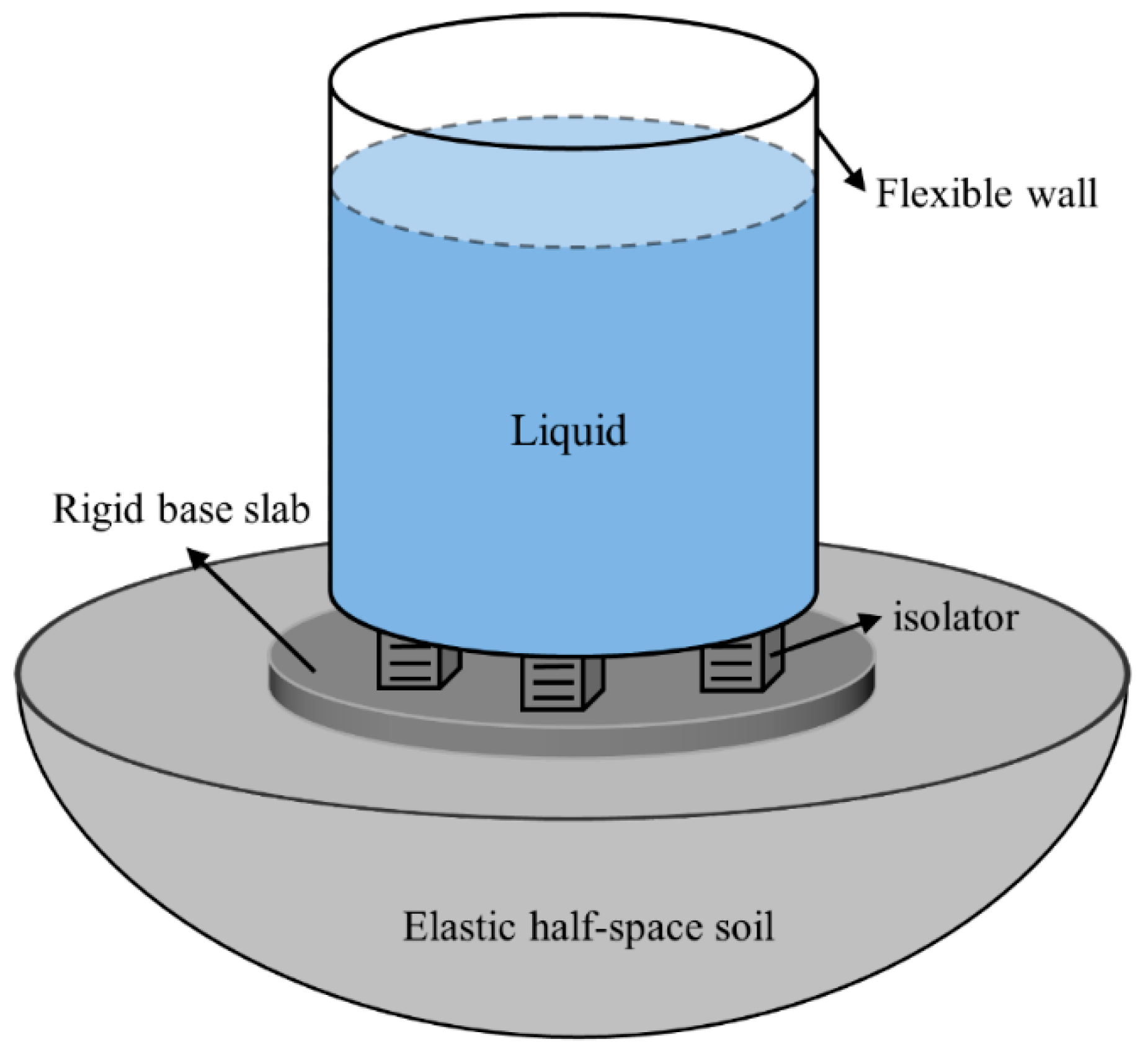
2. Mathematical Model of the Soil–Tank–Liquid System

A base-isolated flexible cylindrical tank partially filled with liquid is supported on elastic soil undergoing horizontal excitation in Figure 1. The tank base is assumed to be rigid. The liquid is inviscid, incompressible, and irrotational. The linearized sloshing theory is utilized by taking the small amplitude of the free surface into consideration.

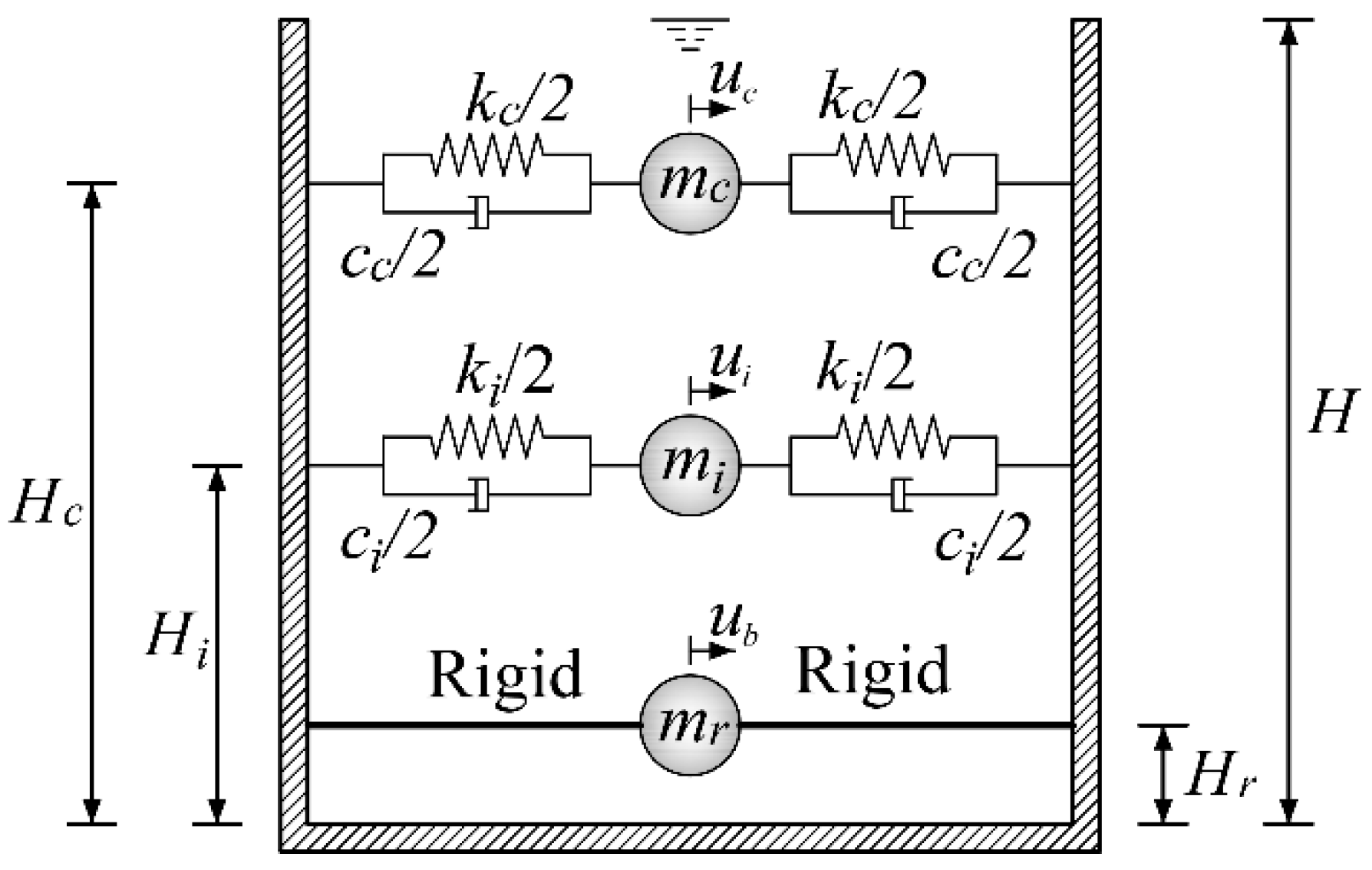
2.1. Tank–Liquid Interaction

The dynamic behavior of the liquid–shell subsystem is simulated by a spring–mass model presented by Haroun and Ellaithy [18] considering the horizontal and rocking movements of the rigid base. Mechanical parameters of the model are expressed as
m i = ( γ 1 2 / γ 7 ) m ,   m r = ( γ 2 γ 1 2 / γ 7 ) m ,
in which m i and m r are the impulsive and rigid masses, respectively; m denotes the mass of liquid with m = π R 2 H ρ l , where R, H, and ρ l denote the tank radius, liquid height, and liquid mass density, respectively; and dimensionless coefficients γ i (i = 1, 2, …, 7) are given by Haroun and Ellaithy [18]. The heights of the impulsive and rigid masses are represented as Hi and Hr, respectively, from the tank bottom. Detailed forms of the heights are expressed as
H i = ( γ 4 / γ 1 ) H ,   H r = ( γ 3 γ 7 γ 1 γ 4 H ) / ( γ 2 γ 7 γ 1 2 ) ,
The inertia moment of the rigid mass J r yields
J r = γ 6 m H m r H r 2 m i H i 2 .
The stiffness and damping of the impulsive mass has [18]
k i = 4 π E s t h s t m i m ( 0.000335 S 3 0.000021 S 2 0.016361 S + 0.065598 ) 2 ,
c i = 2 ζ i k i m i ,
in which S = H/R represents the tank aspect ratio; Est represents the elastic modulus of the wall; hst is the wall thickness; and ζi represents the damping factor of the impulsive mass.
For free surface sloshing in a similar rigid tank, the sloshing mass mc, the corresponding height Hc and the spring stiffness kc as well as the damping cc are obtained as [18]
m c = 0.455 π ρ l R 3 tanh ( 1.84 H R ) ,
H c = [ 1 R 1.84 t a n h ( 0.92 H R ) ] ,
k c = m c ω c 2 ,
c c = 2 ζ c m c ω c ,
ω c = 1.84 g R t a n h ( 1.84 H R ) ,
in which g denotes the gravity acceleration; ωc represents the associated sloshing natural frequency; and ζc represents the damping factor of the convective mass. The damping ratios and impulsive masses of sloshing are 0.005 and 0.02, given by Kim and Lee [41], respectively. The equivalent model of the considered tank is shown in Figure 2. It should be emphasized that the correctness and accuracy of the equivalent mechanical model of the liquid-flexible tank system has been validated by authors [19].

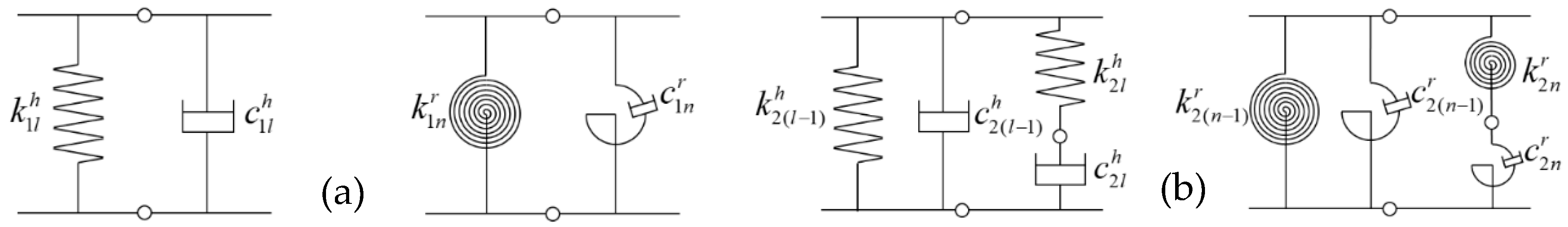
2.2. Soil–Foundation Dynamic Interaction

The base-isolated tank is supported on the elastic half-space overlying the rigid bedrock. Wu and Lee [42] proposed the efficient systematic lumped-parameter models (SLPMs) with frequency-independent parameters to describe the soil impedances. In this study, the SLPMs are employed to simulate the impedances of a circular surface foundation in a frequency range of interest. Utilizing two basic discrete-element models (seen in Figure 3), the horizontal and rocking impedances are represented using two SLPMs with Nh and Nr degrees of freedom, respectively. Q and P are the orders of corresponding second-order discrete-element models. The spring and damping coefficients of two SLPMs are [41]
k j l h = γ j l h K s h ,   c j l h = δ j l h R b V s K s h ,   ( l = 1 , ,   N h ) ,
k j n r = γ j n r K s r ,   c j n r = δ j n r R b V s K s r ,   ( n = 1 , ,   N r ) ,
in which k j l h and c j l h represent the spring and damping coefficients of horizontal SLPMs, respectively, k j n r and c j n r represent the spring and damping coefficients of rocking SLPMs, respectively. R b represents the foundation radius. The first notation (j = 1, 2) of the subscript denotes the type of the basic discrete-element model. K s h and K s r are the horizontal and rocking static impedances of the soil–foundation interactions, respectively. V s represents the shear wave velocity of the soil. The coefficients γ j l h , δ j l h , γ j n r , and δ j n r are the nondimensional spring and damping parameters for the model.

2.3. Soil–Tank Coupling System with the Base Isolator

In Figure 4, the isolators are regarded as laminated rubber bearings (LRBs) characterized by the linear force–deformation hysteresis given by Jangid and Datta [43]. Fb denotes the isolator restoring force.
The mass of the base slab m b between the isolation system and soil (seen in Figure 1) is considered as 5% of the liquid mass. The movement equation for the base-isolated storage tank resting on the elastic soil under the horizontal excitation can be obtained from Hamilton’s principle:
δ t 1 t 2 T V d t + t 1 t 2 δ W d t
The kinetic energy T and potential energy V for the coupling system yield
T = 1 2 m c x ˙ c + x ˙ b + H c φ ˙ 11 r + u ˙ g 2 + 1 2 m i x ˙ i + x ˙ b + H i φ ˙ 11 r + u ˙ g 2 + 1 2 m r + m b x ˙ b + H r φ ˙ 11 r + u ˙ g 2 + 1 2 J r + m b ( 3 R 2 + h c r 2 ) / 12 φ ˙ 11 r 2 ,
V = 1 2 k c x c 2 + 1 2 k i x i 2 + 1 2 k b x b x 11 h 2 + 1 2 l = 1 N h 2 Q k 1 l h x 1 l h x 1 ( l + 1 ) h 2 + 1 2 k 1 ( N h + 1 2 Q ) h x 1 ( N h + 1 2 Q ) h x 21 h 2 + 1 2 l = 1 , 3 , , 2 Q 3 k 2 l h x 2 l h x 2 ( l + 2 ) h 2 + k 2 ( l + 1 ) h x 2 l h x 2 ( l + 1 ) h 2 + 1 2 k 2 ( 2 Q 1 ) h x 2 ( 2 Q 1 ) h 2 + 1 2 k 2 ( 2 Q ) h x 2 ( 2 Q 1 ) h x 2 ( 2 Q ) h 2 + 1 2 n = 1 N r 2 P k 1 n r φ 1 n r φ 1 ( n + 1 ) r 2 + 1 2 k 1 ( N r + 1 2 P ) r φ 1 ( N r + 1 2 P ) r φ 21 r 2 + 1 2 n = 1 , 3 , , 2 P 3 k 2 n r φ 2 n r φ 2 ( n + 2 ) r 2 + k 2 ( n + 1 ) r φ 2 n r φ 2 ( n + 1 ) r 2 + 1 2 k 2 ( 2 P 1 ) r φ 2 ( 2 P 1 ) r 2 + 1 2 k 2 ( 2 P ) r φ 2 ( 2 P 1 ) r φ 2 ( 2 P ) r 2 .
The dissipated energy of damping forces δW has
δ W = c c x ˙ c δ x c c i x ˙ i δ x i c b ( x ˙ b x ˙ 11 ) δ ( x b x 11 h ) l = 1 N h 2 Q c 1 l h x ˙ 1 l h x ˙ 1 ( l + 1 ) h × δ x 1 l h x 1 ( l + 1 ) h l = 1 , 3 , , 2 Q 3 c 2 l h x ˙ 2 l h x ˙ 2 ( l + 2 ) h δ x 2 l h x 2 ( l + 2 ) h + c 2 ( l + 1 ) h x ˙ 2 ( l + 1 ) h x ˙ 2 ( l + 2 ) h δ x 2 ( l + 1 ) h x 2 ( l + 2 ) h c 1 ( N h + 1 2 Q ) h x ˙ 1 ( N h + 1 2 Q ) h x ˙ 21 h × δ x 1 ( N h + 1 2 Q ) h x 21 h c 2 ( 2 Q 1 ) h x ˙ 2 ( 2 Q 1 ) h δ x 2 ( 2 Q 1 ) h c 2 ( 2 Q ) h x ˙ 2 ( 2 Q ) h δ x 2 ( 2 Q ) h n = 1 N r 2 P c 1 n r φ ˙ 1 n r φ ˙ 1 ( n + 1 ) r δ φ 1 n r φ 1 ( n + 1 ) r c 1 ( N r + 1 2 P ) r φ ˙ 1 ( N r + 1 2 P ) r φ ˙ 21 r × δ φ 1 ( N r + 1 2 P ) r φ 21 r n = 1 , 3 , , 2 P 3 c 2 n r φ ˙ 2 n r φ ˙ 2 ( n + 2 ) r δ φ 2 n r φ 2 ( n + 2 ) r + c 2 ( n + 1 ) r φ ˙ 2 ( n + 1 ) r φ ˙ 2 ( n + 2 ) r δ φ 2 ( n + 1 ) r φ 2 ( n + 2 ) r c 2 ( 2 P 1 ) r φ ˙ 2 ( 2 P 1 ) r δ φ 2 ( 2 P 1 ) r c 2 ( 2 P ) r φ ˙ 2 ( 2 P ) r δ φ 2 ( 2 P ) r .
in which k b and c b denote the stiffness and viscous damping for the isolator, respectively. The geometry dimension of the base slab is considered as R with the thickness h c r . The LRB isolator is featured by the isolation time period T b and the isolation damping ratio ξ b , with T b = 2 π M / k b and ξ b = c b / 2 M k b , where M is the total mass of the base-isolated tank. The mechanical model for the soil–tank–liquid coupling system with the base isolator is illustrated in Figure 5.
Substituting Equations (14)–(16) into Equation (13) obtains the governing equation of system motion:
M x ¨ + C x ˙ + K x = M r u ¨ g ,
in which [M], [C], and [K] represent the mass, damping, and stiffness matrices, respectively, with the detailed expressions given in Appendix A; u ¨ g denotes the horizontal acceleration at the bedrock; x = x c , x i , x b , { x j l h } , { φ j n r }  denotes the generalized displacement vector; x c = u c u b denotes the displacement of the sloshing mass relative to that of the tank base; x i = u i u b denotes the displacement of the impulsive mass relative to that of the tank base; x b = u b u g denotes the base displacement at the top of the isolation bearing relative to that at the bedrock; u c , u i and u b are absolute displacements of the convective mass, impulsive mass, and the isolator top, respectively; x j l h represents the horizontal displacement of lth degree of freedom of the SLPM relative to that at the bedrock; φ j n r represents the rotation angle of the nth degree of freedom of the SLPM relative to that at the bedrock; and r = 0 , 0 , 0 , 1 , 0 , , 0 represents the coefficient vector representing impacts of the excitation direction on the load. J b is the base inertia moment. The linear Newmark-β approach is employed to obtain the dynamic responses of the tank system. Thus, the base shear V b and base moment M b have
V b = m c ( x ¨ c + x ¨ b + x ¨ 11 h + H c φ ¨ 11 r + u ¨ g ) + m i ( x ¨ i + x ¨ b + x ¨ 11 h + H i φ ¨ 11 r + u ¨ g ) + m r ( x ¨ b + x ¨ 11 h + H r φ ¨ 11 r + u ¨ g ) ,
M b = m c H c ( x ¨ c + x ¨ b + x ¨ 11 h + H c φ ¨ 11 r + u ¨ g ) + m i H i ( x ¨ i + x ¨ b + x ¨ 11 h + H i φ ¨ 11 r + u ¨ g ) + m r H r ( x ¨ b + x ¨ 11 h + H r φ ¨ 11 r + u ¨ g ) + ( J r + J b ) φ ¨ 11 r .

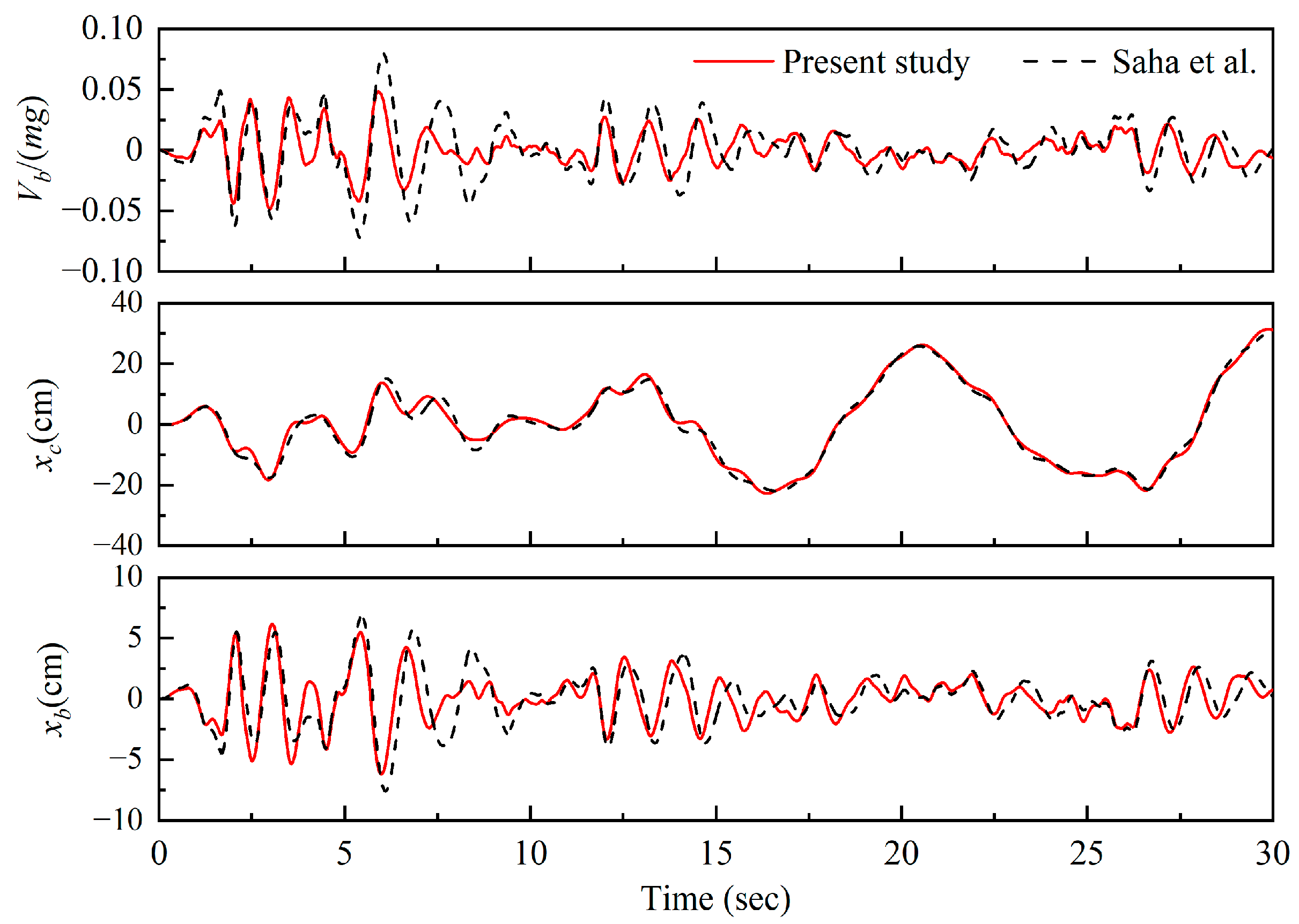
3. Model Verification

The time history of the liquid tank on the rigid foundation with Vs = 5000 m/s is in comparison with the published results from Saha et al. [44]. The component S00E of the Imperial Valley earthquake recorded at El Centro station in 1940 is utilized. The peak value of seismic acceleration excitation is 0.348 g. The tank parameters are considered as S = 0.6 and H = 14.6 m. The thickness of the tank is hst/R = 0.004. The elastic modulus of the steel tank is fixed at Est = 200 GPa, with the tank mass density ρst fixed at 7900 kg/m3 and the liquid mass density fixed at ρl = 1000 kg/m3. The isolation time period for the LRB isolator is T b = 2 s. The isolation damping ratio is ξ b = 0.1. Figure 6 plots the time history of the normalized base shear Vb/(mg) and the sloshing displacement xc as well as the base displacement xb. It is observed that the present results show an acceptable agreement with the reported ones, which implies the validity and feasibility of the present method. However, there is a discrepancy in the peak values of the normalized base shear between the present result and the existing result. It may be initiated from Saha’s assumption of the rigid foundation.

4. Parameter Analysis and Results

Two kinds of different tank configurations, namely, the broad tank (S = 0.6, H = 14.6 m) and the slender tank (S = 1.85, H = 11.3 m), are considered. The thicknesses of the broad and slender walls hst are considered as 0.0973 m and 0.0244 m, respectively. The spring and damping parameters, given in Equation (6), of the SLPM of the circular surface footing on the half-space soil medium with Poison’s ratio equal to 1/3 are adopted from Wu and Lee [40]. The three earthquake records considered in this study are the S00E, E90W, and N00S components of the Imperial Valley (1940), Northridge (1994), and Kobe (1995) seismic input movements recorded at the El Centro, Newhall, and JMA stations, respectively. The peak input accelerations of the three waves are 0.348 g, 0.583 g, and 0.834 g, respectively. Figure 7 shows the time histories and response spectra of the waves. Significantly, because the ratio of the sloshing displacement to the tank radius is consistent with the linear sloshing theory, the selection of the peak input accelerations of three waves is reasonable. The following analyses provide the detailed calculation results of the sloshing displacement. The spillage of the fluid from the top of the tank in open-top tanks or damage to the upper part of the wall or the roof for closed-top tanks is not ignored in the present study.

4.1. Effectiveness of Base Isolation

Figure 8 shows the time history of the seismic responses of the broad and slender tanks resting on the soft soil undergoing Imperial Valley earthquake excitation. As can be observed from Figure 8, the base shear and impulsive displacement of isolated tanks on soil are remarkably mitigated in comparison with those of non-isolated ones on soil. The decrease in base shear can reduce the thickness of the wall and makes for a more economic design. Additionally, the decrease in the impulsive displacement leads to a decline in the local buckling of the wall. However, the amplification in the sloshing displacement is found for the tanks with inclusion of isolation systems. This could be attributed to the truth that the lower natural period of the tank caused by the base isolation is closer to that of the sloshing mass.
Table 1 gives the peak responses for the broad and slender tanks resting on the soft soil subjected to the selected seismic input motions. It is obtained from Table 1 that the average percentages of the base shear reduction of isolated broad and slender tanks can reach 61% and 76%, respectively, in comparison with those of non-isolated ones. Similarly, the average percentages of the impulsive displacement reduction can reach 56% and 73%, respectively. Moreover, the decrease in the base shear and impulsive displacement of the slender tank is remarkably larger than that of the broad one, indicating that the slender tanks are more sensitive to the isolation system than the broad tanks.

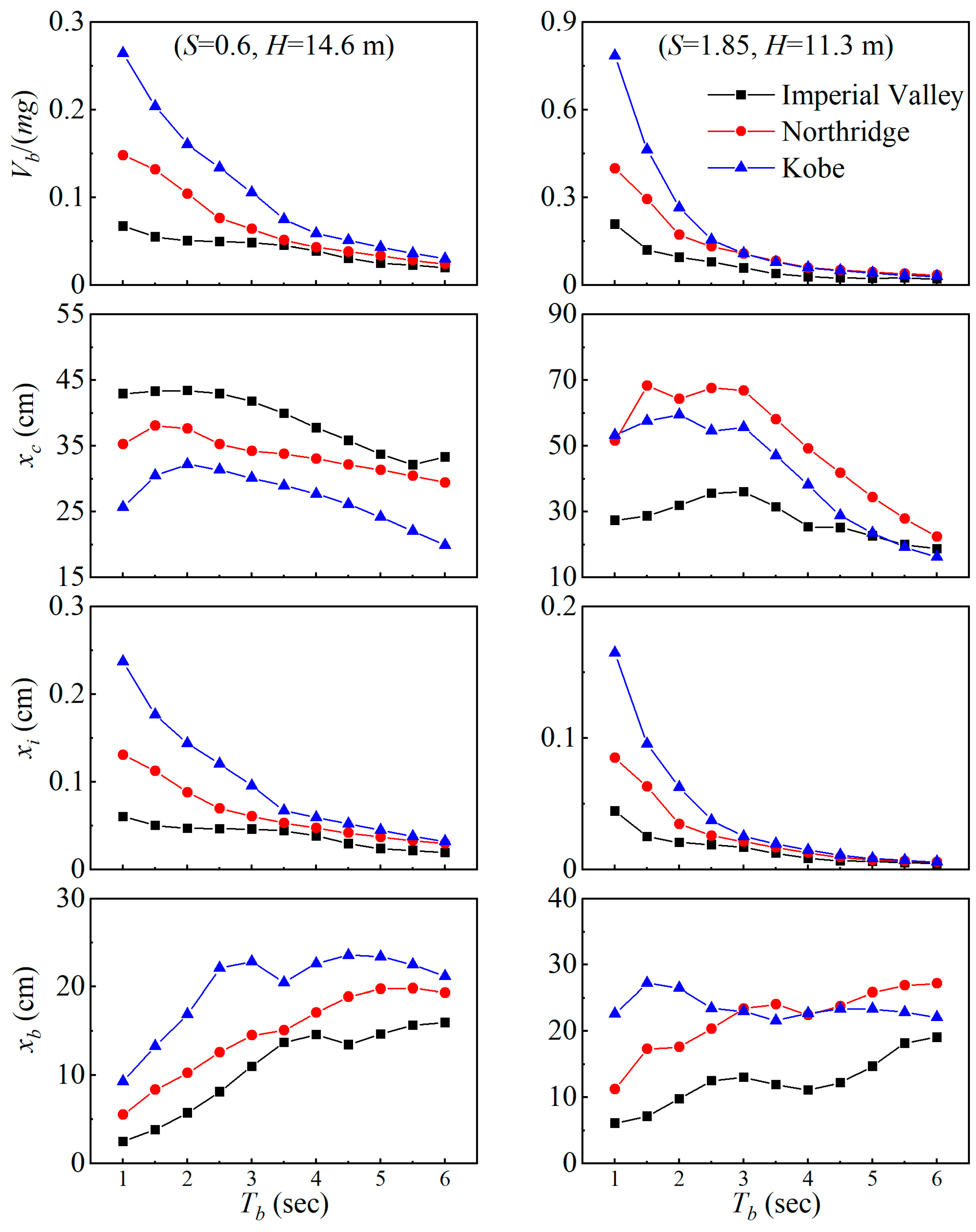
4.2. Effect of Isolation Period

Consider the isolation damping ratio ξb equal to 0.1. Effects of the isolation period Tb on the peak responses of the broad and slender tanks on the soft soil undergoing selected earthquake waves are reflected in Figure 9. It is clear that the base shear and impulsive displacement decline with increasing Tb. The increasing isolation period Tb makes the overall system become more flexible. Moreover, when Tb is less than 3 s, the base shear and impulsive displacement are remarkably dependent on driving motion. However, when Tb moves from 3 to 6 s, the base shear and impulsive displacement both decline slowly. The various seismic input motions have little effect on the base shear and impulsive displacement. In Figure 9, the sloshing displacements rely on the isolation period as well as the earthquake wave. The increase in Tb from 1 to 2 s induces the increase in sloshing displacements. When Tb is between 2 and 3 s, the peak values sloshing displacement can be obtained. With a further increase in Tb from 3 to 6 s, the sloshing displacements are declined. The base displacements generally increase with the increase in Tb.

4.3. Effect of Isolation Damping Ratio

The isolation period is considered as Tb = 2 s. The variations in the peak responses of the broad and slender tanks against the isolation damping ratio ξb under the soft soil are illustrated in Figure 10. The results indicate that the base shear and impulsive displacement decrease as the isolation damping ratio ξb grows up to about ξb = 0.15 for the broad tank and up to about ξb = 0.2 for the slender tank, where the minimum base shear and impulsive displacement are attained. Then, there is a sudden increase in the base shear and impulsive displacement. Thus, it can be concluded that there exists an optimum value for the isolation damping ratio of the isolation system that induces minimum dynamic responses. The sloshing and base displacements gradually reduce with the increase in ξb, dissipating more earthquake energy.

4.4. Effect of Tank Aspect Ratio

Soft soil (Vs = 100 m/s, ρs = 1800 kg/m3) and stiff soil (Vs = 508 m/s, ρs = 2400 kg/m3) are considered. Figure 11 depicts the effects of the change in the tank aspect ratio from 0.5 to 4.0 on the peak seismic responses under considered earthquakes. It should be mentioned that the liquid volume is kept constant at 104 m3 for all cases of the tank aspect ratios with hst = 0.0254 m. It is clear that the maximum base shear without the inclusion of isolators is sensitive to variation in the tank aspect ratio H/R and earthquake excitation. However, the application of the base isolation brings about a significant drop in the base shear.
In Figure 11, in general, the sloshing displacement increases with the increase in H/R. The sloshing displacement of the isolated tank is amplified by an order of 15–110% in comparison with that of the non-isolated one. This is attributed to the higher flexibility induced by the isolation device. Such an increase should be considered to provide the cylindrical tanks with sufficient freeboard, which prevents the spillage of liquid.
Also, it is observed that the impulsive displacement of the non-isolated tank is noticeably increased with increasing the liquid filling ratio. However, the impulsive displacement of the isolated tank illuminates a very marginal increase with the height of the tank radius ratio and is much less than that of the non-isolated one, which leads to a decline in the local buckling occurrence at the bottom of the steel wall. The base displacement slightly increases for H/R < 2. The base displacement seems to be almost flat in terms of the aspect ratio in the range of 2 to 4. The above results indicate the effectiveness of base isolation in decreasing the peak values of important response quantities for the tanks with all aspect ratios, H/R.

4.5. Effect of Soil–Structure Dynamic Interaction

The isolation period Tb and damping ratio ξb are 2 s and 0.1, respectively. To estimate dynamic responses of the tank sited on the deformable foundation, the various shear wave velocities of the supported soil Vs from 100 m/s (soft soil) to 1000 m/s (rigid foundation) are accounted for. The soil density is 1800 kg/m3. Influences of the flexible foundation on the responses of base-isolated tanks are displayed in Figure 12 under the different seismic waves.
It is obvious that the SSI effects on the dynamic responses are sensitive to seismic excitation. When Vs is less than 250 m/s, there is amplification of the base shear and displacements as the shear wave velocity Vs increases. The peak values of three structural responses are not affected by the further increase in soil stiffness. However, when the foundation soil becomes flexible, the sloshing displacement remains nearly unchanged.
In addition, the fundamental periods of the impulsive and convective components of the soil-isolation bearing–tank–liquid system are given in Table 2. It is found that the SSI remarkably affects the impulsive fundamental periods. The increase in the impulsive fundamental periods occurs as the soil stiffness declines. However, the foundation deformability has an insignificant influence on the convective fundamental periods. Therefore, this explains that the sloshing displacement does not depend on the change in the foundation properties.

5. Conclusions

The seismic behaviors of the cylindrical tanks isolated by the laminated rubber bearing resting on the elastic soil are reported. Two typical tanks with different configurations and two soil types are taken into account. Practical and useful ranges of the isolation period and damping ratio are considered. A comparison is made between non-isolated and isolated conditions to evaluate the effectiveness of the base isolation in the response reduction. Furthermore, the parameter investigation is performed to examine the influences of the characteristic properties of the isolator, tank aspect ratio, and soil stiffness on the dynamics of tanks. The conclusions are stated as follows:
  • When the base isolation is considered, the base shear and impulsive displacement can be reduced drastically. This result implies that seismic base isolation is an efficient way to reduce the tank responses. Moreover, the isolation system is more effective for the slender tanks in comparison with the broad ones.
  • There exists an amplification in the sloshing displacement due to isolation, especially for the slender tanks. Also, the flexibility of the isolator causes the excessive base displacements between the superstructure and the foundation.
  • As the isolation period grows, the isolation efficiency also increases. The base displacement, however, is greater in terms of the larger values of the isolation period. With the growth of the isolation damping ratio, the base displacement gradually decreases, whereas the excessive isolation damping ratio causes the increasing base shear and impulsive displacement.
  • For the isolated tanks, the effect of the tank aspect ratio on the base shear and impulsive displacement can be negligible. When Vs is less than 250 m/s, there is an amplification of the base shear, sloshing displacement, and base displacement as the shear wave velocity Vs increases. However, the sloshing displacement remains nearly unchanged with the soil becoming flexible.
The present study proposes a coupled mechanical model of a base-isolated cylindrical tank resting on homogeneous elastic soil. A seismic analysis is performed through selecting three earthquake waves. Further investigations will be carried out for base-isolated cylindrical tanks with annular baffles, which can reduce the sloshing displacements to avoid spillage of the fluid from the top of the tank in open-top tanks or damage to the upper part of the wall or the roof for closed-top tanks; moreover, a large number of earthquake waves are also considered to examine their effects on the performance of the isolators to draw a general conclusion on the reduction percentage points for structural responses of the system.

Author Contributions

Conceptualization, Y.S.; methodology, X.M.; software; validation, X.M.; formal analysis, X.M.; investigation, X.M.; resources, X.M., Y.S., H.H. and D.Z.; data curation, X.M.; writing—original draft preparation, X.M.; writing—review and editing, C.W., H.H. and D.Z.; visualization, X.M. and C.W.; supervision, Y.S.; project administration, H.H. and D.Z.; funding acquisition, H.H. and D.Z. All authors have read and agreed to the published version of the manuscript.

Funding

This research was funded by the Natural Science Foundation of Jiangsu Province (Grant Nos. BK20240942 and BK20210872), the Natural Science Foundation of the Jiangsu Higher Education Institutions of China (Grant Nos. 24KJB130005, 22KJB560031, and 21KJB560004), the National Natural Science Foundation of China (Grant Nos. 51978336 and 52108149), and the China Postdoctoral Science Foundation (2021M690623), and school-level research projects of the Yancheng Institute of Technology (xjr2023016), and the APC was funded by school-level research projects of the Yancheng Institute of Technology (xjr2023016).

Data Availability Statement

The datasets used and/or analyzed during the current study are available from the corresponding author on reasonable request.

Conflicts of Interest

Author Chi Wang was employed by the company State Grid Jiangsu Electric Power Engineering Consulting Co., Ltd. The remaining authors declare that the research was conducted in the absence of any commercial or financial relationships that could be construed as a potential conflict of interest.

Appendix A

The matrices [M], [C], and [K] are defined as follows:
M = m c 0 m c m c { 0 } ( N h 1 ) m c H c { 0 } ( N r 1 ) 0 m i m i m i { 0 } ( N h 1 ) m i H i { 0 } ( N r 1 ) m c m i M M { 0 } ( N h 1 ) m c H c + m i H i + m r H r { 0 } ( N r 1 ) m c m i M M + m b { 0 } ( N h 1 ) m c H c + m i H i + ( m r + m b ) H r { 0 } ( N r 1 ) { 0 } ( N h 1 ) T { 0 } ( N h 1 ) T { 0 } ( N h 1 ) T { 0 } ( N h 1 ) T [ 0 ] ( N h 1 ) × ( N h 1 ) T { 0 } ( N h 1 ) T [ 0 ] ( N h 1 ) × ( N r 1 ) T m c H c m i H i m c H c + m i H i + m r H r ( m r + m b ) H r + m c H c + m i H i { 0 } ( N h 1 ) ( m r + m b ) H r 2 + m c H c 2 + m i H i 2 + J r + J b { 0 } ( N r 1 ) { 0 } ( N r 1 ) T { 0 } ( N r 1 ) T { 0 } ( N r 1 ) T { 0 } ( N r 1 ) T [ 0 ] ( N r 1 ) × ( N h 1 ) T { 0 } ( N r 1 ) T [ 0 ] ( N r 1 ) × ( N r 1 ) T ( N + N h + N r + 2 ) × ( N + N h + N r + 2 )
C = C f C s h C s r ,   K = K f K s h K s r ,   K f = k c k i ,   C f = c c c i ,
C s h = c b c b 0 0 0 c b c 11 h + c b c 11 h 0 c 11 h c 11 h + c 12 h c 12 h c 12 h c 1 ( N h + 1 2 Q ) h c 1 ( N h + 1 2 Q ) h c 1 ( N h + 1 2 Q ) h + c 21 h 0 c 21 h 0 0 0 c 22 h c 22 h c 2 ( 2 Q 3 ) h c 21 h c 22 h i = 1 , 2 , 3 c 2 i h c 2 ( 2 Q 2 ) h c 2 ( 2 Q 3 ) h c 2 ( 2 Q 2 ) h i = 1 , 2 , 3 c 2 ( 2 Q i ) h 0 0 0 0 c 2 ( 2 Q ) h
C s r = c 11 r c 11 r 0 0 0 c 11 r c 11 r + c 12 r c 12 r 0 c 12 r c 1 ( N r + 1 2 P ) r c 1 ( N r + 1 2 P ) r c N r + 1 2 P r + c 21 r 0 c 21 r 0 0 c 22 r c 22 r 0 c 21 r c 22 r i = 1 , 2 , 3 c 2 i r c 2 ( 2 P 3 ) r c 2 ( 2 P 2 ) r c 2 ( 2 P 3 ) r c 2 ( 2 P 2 ) r i = 1 , 2 , 3 c 2 ( 2 P i ) r 0 0 0 0 0 c 2 ( 2 P ) r
K s h = k b k b 0 0 0 k b k 11 h + k b k 11 h 0 k 11 h k 11 h + k 12 h k 12 h k 12 h k 1 ( N h + 1 2 Q ) h 0 k 1 ( N h + 1 2 Q ) h k 1 ( N h + 1 2 Q ) h + k 21 h + k 22 h k 22 h k 21 h 0 k 22 h k 22 h k 21 h 0 i = 0 , 1 , 3 k 2 ( 2 Q i ) h k 2 ( 2 Q ) h 0 0 0 k 2 ( 2 Q ) h k 2 ( 2 Q ) h
K s r = k 11 r k 11 r 0 0 0 k 11 r k 11 r + k 12 r k 12 r 0 k 12 r k 1 ( N r + 1 2 P ) r 0 k 1 ( N r + 1 2 P ) r k 1 ( N r + 1 2 P ) r + k 21 r + k 22 r k 22 r k 21 r 0 k 22 r k 22 r k 21 r 0 i = 0 , 1 , 3 k 2 ( 2 P i ) r k 2 ( 2 P ) r 0 0 0 k 2 ( 2 P ) r k 2 ( 2 P ) r

References

  1. Zhang, Z.; Xu, J.; Cao, X.; Wang, Y.; Zhu, J.; Yao, L. Nonlinear transient heat transfer analysis of functionally graded material sandwich slabs by incremental differential quadrature element method. Fuhe Cailiao Xuebao/Acta Mater. Compos. Sin. 2024, 41, 6285–6297. [Google Scholar] [CrossRef]
  2. Al-Yacouby, A.M.; Hao, L.J.; Liew, M.S.; Ratnayake, R.M.C.; Samarakoon, S.M.K. Thin-walled cylindrical shell storage tank under blast impacts: Finite element analysis. Materials 2021, 14, 7100. [Google Scholar] [CrossRef] [PubMed]
  3. Sun, Y.; Zhou, D.; Wang, J. An equivalent mechanical model for fluid sloshing in a rigid cylindrical tank equipped with a rigid annular baffle. Appl. Math. Model. 2019, 72, 569–587. [Google Scholar] [CrossRef]
  4. Zhang, Q.; Shui, B.; Zhu, H. Study on sloshing characteristics in a liquid cargo tank under combination excitation. J. Mar. Sci. Eng. 2022, 10, 1100. [Google Scholar] [CrossRef]
  5. Wang, G.; Wang, T. Effect evaluation of filling medium parameters on operating and mechanical performances of liquid heavy metal heat storage tank. Sustainability 2022, 14, 14551. [Google Scholar] [CrossRef]
  6. Zhao, Z.; Hu, X.; Zhang, R.; Xie, M.; Liu, S. Advantages and design of inerters for isolated storage tanks incorporating soil conditions. Thin-Walled Struct. 2024, 195, 111356. [Google Scholar] [CrossRef]
  7. Chaithra, M.; Krishnamoorthy, A.; Avinash, A.R. A review on the modelling techniques of liquid storage tanks considering fluid–structure–soil interaction effects with a focus on the mitigation of seismic effects through base isolation techniques. Sustainability 2023, 15, 11040. [Google Scholar] [CrossRef]
  8. Jing, W.; Feng, H.; Cheng, X. Dynamic responses of liquid storage tanks caused by wind and earthquake in special environment. Appl. Sci. 2019, 9, 2376. [Google Scholar] [CrossRef]
  9. Hosseini, S.E.A.; Beskhyroun, S. Dynamic performance investigation of a full-scale unanchored thin-walled steel fluid storage tank via shake table tests. Structures 2024, 70, 107548. [Google Scholar] [CrossRef]
  10. Haroun, M.A. Vibration studies and tests of liquid storage tanks. Eng. Struct. Dyn. 1983, 11, 179–206. [Google Scholar] [CrossRef]
  11. Cho, J.R.; Lee, S.Y.; Song, M.S. Dynamic response characteristics of cylindrical baffled liquid storage tank to the baffle number. J. Mech. Sci. Technol. 2019, 33, 5979–5987. [Google Scholar] [CrossRef]
  12. Baghban, M.H.; Razavi Tosee, S.V.; Valerievich, K.A.; Najafi, L.; Faridmehr, I. Seismic analysis of baffle-reinforced elevated storage tank using finite element method. Buildings 2022, 12, 549. [Google Scholar] [CrossRef]
  13. Hernandez, D.H.; Larkin, T.; Chouw, N. Shake table investigation of nonlinear soil-structure-fuild interaction of a thin-walled storage tank under earthquake load. Thin-Walled Struct. 2021, 167, 108143. [Google Scholar] [CrossRef]
  14. Lee, J.H.; Lee, S.-H.; Han, S.-W. Nonlinear earthquake responses of unanchored cylindrical liquid storage tanks on flexible soil. Structures 2023, 54, 1465–1490. [Google Scholar] [CrossRef]
  15. Jing, W.; Shen, J.; Cheng, X.; Yang, W. Seismic responses of a liquid storage tank considering structure-soil-structure interaction. Structures 2022, 45, 2137–2150. [Google Scholar] [CrossRef]
  16. Jing, W.; Wang, S.; Shen, J.; Song, S. Influence of seismic wave incidence angle on dynamic responses and vibration control of adjacent liquid storage tanks. Int. J. Struct. Stab. Dyn. 2024, 24, 2450254. [Google Scholar] [CrossRef]
  17. Shan, W.C.; Liu, J.P.; Zhou, J.W. Uplift effect and soil-strucutre interaction on seismic responses of column suppoted steel tanks under multi-dimensional earthquakes. J. Constr. Steel Res. 2025, 226, 109235. [Google Scholar] [CrossRef]
  18. Haroun, M.A.; Ellaithy, H.M. Model for flexible tanks undergoing rocking. J. Eng. Mech. 1985, 111, 143–157. [Google Scholar] [CrossRef]
  19. Meng, X.; Li, X.H.; Xu, X.L.; Zhang, J.D.; Zhou, W.L.; Zhou, D. Earthquake Response of Cylindrical Storage Tanks on Elastic Soil. J. Vib. Eng. Technol. 2019, 7, 433–444. [Google Scholar] [CrossRef]
  20. Sun, Y.; Zhou, D.; Amabili, M.; Wang, J.; Han, H. Liquid sloshing in a rigid cylindrical tank equipped with a rigid annular baffle and on soil foundation. Int. J. Struct. Stab. Dyn. 2020, 20, 2050030. [Google Scholar] [CrossRef]
  21. Meng, X.; Zhou, D.; Lim, Y.M.; Wang, J.D.; Huo, R.L. Ssismic Response of Rectangular Liquid Container with Dual Horizontal Baffles on Deformable Soil Foundation. J. Earthq. Eng. 2023, 27, 1943–1972. [Google Scholar] [CrossRef]
  22. Peng, Q.; Wu, H.; Zhang, R.F.; Fang, Q. Numerical simulations of base-isolated LNG storage tanks subjected to large commercial aircraft crash. Thin-Walled Struct. 2021, 163, 107660. [Google Scholar] [CrossRef]
  23. Kalantari, A.; Nikoomanesh, M.R.; Goudarzi, M.A. Applicability of mass-spring models for seismically isolated liquid storage tanks. J. Earthq. Tsunami. 2019, 13, 1950002. [Google Scholar] [CrossRef]
  24. Jing, W.; Feng, J.; Wang, S.; Song, S. Failure probability of a liquid storage tank with three-dimensional base-isolation under earthquake action. Structures 2023, 58, 105633. [Google Scholar] [CrossRef]
  25. Rawat, A.; Matsagar, V.A.; Nagpal, A.K. Numerical study of base-isolated cylindrical liquid storage tanks using coupled acoustic-structural approach. Soil Dyn. Earthq. Eng. 2019, 119, 196–219. [Google Scholar] [CrossRef]
  26. Zhu, H.P.; Tang, Z.A.; Luo, H. Feasibility analyses of negative-stiffness dampers for seismic performance enhancement of a base-isolated liquid storage tank. Soil Dyn. Earthq. Eng. 2023, 164, 107575. [Google Scholar] [CrossRef]
  27. Zhang, R.; Weng, D.; Ge, Q. Shaking table experiment on a steel storage tank with multiple friction pendulum bearings. Struct. Eng. Mech. 2014, 52, 875–887. [Google Scholar] [CrossRef]
  28. Yue, H.; Zhenyun, T.; Zhenbao, L.; Xiuli, D. Seismic performance evaluation of VCFPB isolated storage tank using real-time hybrid simulation. Earthq. Eng. Eng. Vib. 2022, 21, 501–515. [Google Scholar] [CrossRef]
  29. Yu, Q.-Q.; Wu, J.-Y.; Gu, X.-L.; Zhou, F.-Y. Experimental study on effects of U-shape dampers on earthquake responses of a base-isolated LNG inner tank. Eng. Struct. 2022, 269, 114841. [Google Scholar] [CrossRef]
  30. Kumar, H.; Saha, S.K. Effects of uncertain soil parameters on seismic responses of fixed base and base-isolated liquid storage tanks. J. Earthq. Eng. 2024, 28, 176–201. [Google Scholar] [CrossRef]
  31. Cheng, X.; Jing, W.; Chen, J.; Zhang, X. Pounding dynamic responses of sliding base-isolated rectangular liquid-storage structure considering soil-structure interactions. Shock Vib. 2017, 2017, 1–14. [Google Scholar] [CrossRef]
  32. Kumar, H.; Saha, S.K. Effects of soil-structure interaction on seismic response of fixed base and base isolated liquid storage tanks. J. Earthq. Eng. 2022, 26, 6148–6171. [Google Scholar] [CrossRef]
  33. Shekari, M.R.; Hekmatzadeh, A.A.; Amiri, S.M. On the nonlinear dynamic analysis of base-isolated three-dimensional rectangular thin-walled steel tanks equipped with vertical baffle. Thin-Walled Struct. 2019, 138, 79–94. [Google Scholar] [CrossRef]
  34. Shekari, M.R. A coupled BE–FE–BE study for investigating the effect of earthquake frequency content and predominant period on seismic behavior of base-isolated concrete rectangular liquid tanks. J. Fluids Struct. 2018, 77, 19–35. [Google Scholar] [CrossRef]
  35. Shourestani, S.; Soltani, F.; Ghasemi, M.; Etedali, S. SSI effects on seismic behavior of smart base-isolated structures. Geomech. Eng. 2018, 14, 161–174. [Google Scholar] [CrossRef]
  36. Li, Z.; Zhang, R.; Liu, X.; Chen, S.; Li, X. Analysis of seismic response of a large-scale isolated LNG tank considering dynamic soil-pile interaction. Structures 2023, 58, 105460. [Google Scholar] [CrossRef]
  37. Luo, C.; Mu, H.; Wang, H.; Guo, X.; Liu, D.; Feng, H. Study on the seismic mitigation effects of inerter isolated storage tanks. Soil Dyn. Earthq. Eng. 2023, 173, 108140. [Google Scholar] [CrossRef]
  38. Zhao, M.; Zhou, J. Review of seismic studies of liquid storage tanks. Struct. Eng. Mech. 2018, 65, 557–572. [Google Scholar] [CrossRef]
  39. Sun, J.; Cui, L.; Li, X.; Wang, Z.; Liu, W.; Lv, Y. Design theory and method of LNG isolation. Earthq. Struct. 2019, 16, 1–9. [Google Scholar] [CrossRef]
  40. Zhang, H.; Song, C.; Wang, M.; Cheng, Y.; Yue, S.; Wu, C. A geotechnical seismic isolation system based on marine sand cushion for attenuating ground shock effect: Experimental investigation. Soil Dyn. Earthq. Eng. 2023, 168, 107854. [Google Scholar] [CrossRef]
  41. Kim, N.-S.; Lee, D.-G. Pseudodynamic test for evaluation of seismic performance of base-isolated liquid storage tanks. Eng. Struct. 1995, 17, 198–208. [Google Scholar] [CrossRef]
  42. Wu, W.-H.; Lee, W.-H. Systematic lumped-parameter models for foundations based on polynomial-fraction approximation. Earthq. Eng. Struct. Dyn. 2002, 31, 1383–1412. [Google Scholar] [CrossRef]
  43. Jangid, R.S.; Datta, T.K. Seismic behavior of base-isolated buildings: A state-of-the-art-review. Struct. Build. 1995, 110, 186–203. [Google Scholar] [CrossRef]
  44. Saha, S.K.; Matsagar, V.A.; Jain, A.K. Earthquake response of base-isolated liquid storage tanks for different isolator models. J. Earthq. Tsunami. 2014, 08, 1450013. [Google Scholar] [CrossRef]
Figure 1. The base-isolated cylindrical tank resting on soil.
Infrastructures 10 00136 g001
Figure 2. Equivalent mechanical model for the liquid storage tank.
Infrastructures 10 00136 g002
Figure 3. Basic discrete-element models: (a) first-order model; (b) second-order model.
Infrastructures 10 00136 g003
Figure 4. Laminated rubber bearing (LRB) isolator: (a) the profile; (b) the linear force–deformation behavior.
Infrastructures 10 00136 g004
Figure 5. Mechanical model of the soil–tank–liquid coupling system with the base isolator.
Infrastructures 10 00136 g005
Figure 6. Comparison of the present responses with those from Saha et al. [44]. for the isolated storage tank undergoing El Centro wave.
Infrastructures 10 00136 g006
Figure 7. The time histories and response spectra of the selected seismic waves.
Infrastructures 10 00136 g007
Figure 8. Time histories of the seismic responses of the broad and slender tanks resting on the soft soil (Vs = 100 m/s, ρs = 1800 kg/m3).
Infrastructures 10 00136 g008
Figure 9. Effects of the isolation period Tb on the peak responses of the isolated tanks on the soft soil (Vs = 100 m/s; ρs = 1800 kg/m3).
Infrastructures 10 00136 g009
Figure 10. Effects of the isolation damping ratio ξb on the peak responses of the isolated tanks on soft soil (Vs = 100 m/s; ρs = 1800 kg/m3).
Infrastructures 10 00136 g010
Figure 11. Effects of tank aspect ratio H/R on peak responses of the isolated tank (Tb = 2 s, ξb = 0.1).
Infrastructures 10 00136 g011
Figure 12. Effects of soil stiffness on the peak responses of the isolated tank (Infrastructures 10 00136 i001 Imperial Valley; Infrastructures 10 00136 i002 Northridge; Infrastructures 10 00136 i003 Kobe).
Infrastructures 10 00136 g012
Table 1. The peak responses for the broad and slender tanks resting on the soft soil (Vs = 100 m/s, ρs = 1800 kg/m3).
EarthquakeType of TankNon-Isolated TankIsolated Tank
Vb/mgxc (cm)xi (cm)Vb/mgxc (cm)xi (cm)
Imperial
Valley
Broad0.16742.40.1300.05143.50.047
Slender0.40125.70.0770.09531.90.021
NorthridgeBroad0.20930.00.1690.10437.60.088
Slender0.63750.00.1330.17364.40.035
KobeBroad0.42325.90.3380.16132.20.144
Slender1.24941.50.2510.26659.50.063
Table 2. Model analysis results of the overall system under different Vs (m/s).
Type of TankImpulsive Fundamental Period (s)Convective Fundamental Period (s)
Vs = 100Vs = 200Vs = 300Vs = 400Vs = 500Vs = 700Vs = 1000Vs = 100Vs = 200Vs = 300Vs = 400Vs = 500Vs = 700Vs = 1000
Broad tank1.581.351.301.291.281.271.278.388.328.318.318.308.308.30
Slender tank1.771.701.691.691.681.681.683.853.833.823.823.823.823.82
Disclaimer/Publisher’s Note: The statements, opinions and data contained in all publications are solely those of the individual author(s) and contributor(s) and not of MDPI and/or the editor(s). MDPI and/or the editor(s) disclaim responsibility for any injury to people or property resulting from any ideas, methods, instructions or products referred to in the content.

