Article

Study on the Ablation of Slide Plate by Pantograph–Catenary Arc Based on Pantograph Slide Material

1
Key Laboratory of Opto-Technology and Intelligent Control Ministry of Education, Lanzhou Jiaotong University, Lanzhou 730070, China
2
CRRC Nanjing Puzhen Co., Ltd., Nanjing 210031, China
*
Author to whom correspondence should be addressed.
Infrastructures 2025, 10(10), 276; https://doi.org/10.3390/infrastructures10100276
Submission received: 4 September 2025 / Revised: 29 September 2025 / Accepted: 11 October 2025 / Published: 15 October 2025

Abstract

The ablation of pantograph sliders caused by pantograph–catenary arcing is a critical issue in the operation of pantograph–catenary systems. The arc discharge induces localized high temperatures that lead to the melting and even evaporation of the slider material, resulting in material loss. This phenomenon directly impacts the power supply safety and economic efficiency of trains. This study establishes a mathematical model of pantograph–catenary arcing based on Magneto Hydro Dynamics (MHD) theory, incorporating the physical parameters of the arc as well as electromagnetic, thermal, and radiative phenomena. Through secondary development using COMSOL 6.2 finite element software, the temperature distribution within the arc column region and on the surfaces of the electrode plates in pantograph–catenary arcing was simulated. The effects of the pantograph–catenary gap and slider material on arc ablation were investigated. The results show that with the increase in the distance between the pantograph and catenary, the arc shape lengthens gradually, and the high-temperature area inside the slider material shrinks gradually. When the arc duration is constant, the copper-impregnated carbon slider exhibits the best ablation resistance. Increasing the sublimation latent heat of the slider material enhances its anti-ablation performance. The findings of this study provide a valuable reference for understanding and mitigating surface arc erosion in pantograph–catenary systems.

1. Introduction

As the operating speed of high-speed electric multiple units increased, the dynamic interaction between the pantograph and the catenary became increasingly complicated. Accordingly, research on pantograph–catenary arc phenomena was regarded as essential for advancing the construction and sustainable development of high-speed railway systems in China [1].
The generation of pantograph–catenary arcs was associated with the sliding-contact method of power collection adopted by high-speed electric multiple units (EMUs) [2]. During train operation, high-voltage electrical energy was obtained through the contact between the pantograph strip and the catenary contact wire. Inside the train, the electrical energy was transmitted via the traction main circuit to the traction motors and auxiliary equipment, thereby ensuring high-speed operation.
In actual operation, factors such as mechanical vibration, irregularities in catenary geometry (e.g., height and gradient), and the passage through neutral sections often caused transient separations, leading to arc-off phenomena. This phenomenon was directly related to the quality of the power supply and the stability of train operation. For a long time, the pantograph–catenary relationship had been regarded as one of the core technical issues in high-speed railway operation. Consequently, various optimization measures and advanced technologies have been applied to improve the compatibility between pantograph and catenary, thereby enhancing the reliability of power supply and the overall efficiency of high-speed railway operation [3,4].
Under the influence of the electric field, when the field intensity in the impending contact region exceeded the breakdown threshold of air, electrons in the air were accelerated and ionized, thereby initiating the ionization process and forming a micro-arc [5]. At this stage, the arc was in an unstable state. If the ionization process continued, the arc gradually became stabilized. Once stabilized, a high-temperature plasma channel was formed, in which the current density was extremely high, enabling the current to be conducted from the pantograph to the contact wire. Meanwhile, the generation of the arc was accompanied by intense luminous flashes, a phenomenon commonly referred to as pantograph–catenary arc discharge.
The effects of pantograph–catenary discharge phenomena on the pantograph–catenary system were highly complex and could mainly be summarized in three aspects: (1) High-temperature arcs and strong electromagnetic energy were released during electrical breakdown discharge, under which the carbon strip and contact wire were easily ablated, leading to physical damage and material degradation [6]. (2) Pantograph–catenary arcs generated electromagnetic interference and voltage fluctuations. These effects severely affected data transmission in railway signaling systems, resulting in instability of train operation information and further hindering normal train operation. In addition, communication systems were also likely to malfunction due to electromagnetic interference, which negatively affected the overall safety and efficiency [7,8]. (3) The enormous energy released by pantograph–catenary arcs posed a direct threat to the traction and control systems of the train. When the arc intensity was excessively high, short-circuit or open-circuit failures could occur in the traction power system, potentially causing equipment damage and, in severe cases, endangering the safety and stability of train operation [9].
Since the arc was essentially a plasma involving strong coupling of electric, magnetic, flow, and thermal fields, the MHD model was well-suited to integrate the relationships among these physical fields. In reference [10], a dynamic model of the pantograph–catenary arc was established based on MHD theory, and the dynamic characteristics of the arc during pantograph descent were analyzed. A two-dimensional simplified vacuum arc model was developed using finite element software in reference [11], and the arc motion under different magnetic field intensities was investigated, reflecting the movement state of the arc at various times and the changes in contact temperature. In reference [12], the urban rail pantograph–catenary arc was characterized by high temperatures, which directly acted on the surface of the pantograph–catenary system, causing severe ablation of the pantograph and contact wire and affecting the current transmission of the system. The relationship between arc core temperature, duration, and pantograph–catenary gap was studied. In reference [13], a mathematical model of the arc in a low-voltage circuit breaker was established to investigate the distribution of copper vapor during arc motion and its influence on the arc. In reference [14], arc ablation experiments were conducted using copper-impregnated carbon materials and pure copper electrodes to analyze the interaction mechanism and process between copper-impregnated carbon materials and the arc. Research and development of pantograph strip materials for high-speed trains were considered crucial for the stability, reliability, and efficiency of high-speed railway systems. With the successive development of strip materials, the performance of the strips was essential to ensure safe train operation. Therefore, understanding the arc ablation behavior on different strip materials was of significant importance.
Based on the MHD model, the theoretical foundation and modeling process of pantograph–catenary arcs were first introduced. Assumptions regarding the physical characteristics of arcs under simulation conditions were proposed. By combining the three fundamental equations of fluid dynamics with the electromagnetic field equations, a multi-physics coupling of the arc was carried out using COMSOL finite element software. The arc temperature distribution and the ablation effect on the pantograph strip were obtained. These distributions and related image data were analyzed to investigate the influence of pantograph–catenary distance and pantograph strip materials on arc-induced ablation of the strip.

2. Pantograph–Catenary Model Development

During starting and braking conditions, the ablation effect of the arc on electrode materials was significantly intensified, and even a fracture of the contact wire could be induced, posing potential safety hazards to station operations. In the process of train starting and stopping, frequent raising and lowering of the pantograph were accompanied by extremely high arc currents. It was therefore imperative to conduct an in-depth investigation into the arc plasma and the temperature distribution characteristics at the pantograph–catenary interface so as to reveal the underlying ablation mechanisms.

2.1. Assumed Properties

Pantograph–catenary arcing was inherently a highly complex phenomenon, involving the coupling of multiple physical fields, including electric, magnetic, flow, and thermal fields. In order to enhance computational efficiency, the following assumptions were adopted:
(1)
The initiation of the arc was not included in the simulation. A stable arc was assumed to be present at the start of the analysis.
(2)
The arc plasma was assumed to satisfy local thermal equilibrium.
(3)
The arc plasma was assumed to be electrically neutral, and its physical properties were assumed to vary with temperature.
(4)
Space charge near the electrodes was neglected, and the electrode sheath was assumed to have no influence on arc formation.

2.2. Pantograph–Catenary Arc Model

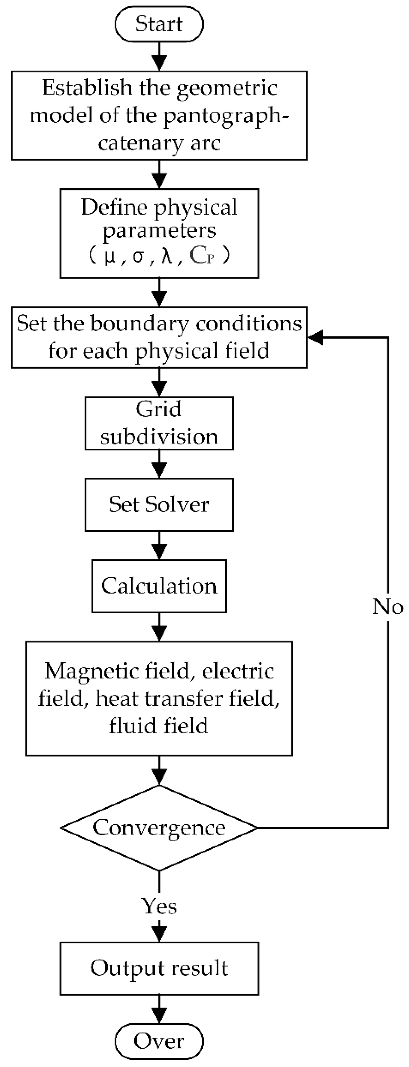
A coupling mechanism among the multiple physical fields during electrode ablation was established, as illustrated in Figure 1. The arc’s physical parameters—including electrical conductivity, specific heat capacity, and viscosity coefficient—served as the fundamental inputs for solving the electromagnetic equations. These parameters largely depended on temperature variations in the thermal field. The electric field was coupled with the magnetic field through electromagnetic induction, and Joule heating induced by the electric field also had a significant impact on the thermal field. The electric and magnetic fields were addressed separately using Faraday’s law and Ampère’s law, respectively. The Lorentz force arising from the electromagnetic field and the Joule heat from the thermal field were the key coupling parameters that linked the three fundamental fluid dynamics equations with the electromagnetic field equations. By solving these coupled equations, the temperature distribution of the arc was obtained. A finite element model of the pantograph–catenary arc temperature field was developed using commercial software, and the modeling process flowchart is shown in Figure 2.

2.3. Establishment of the Pantograph–Catenary Geometric Model

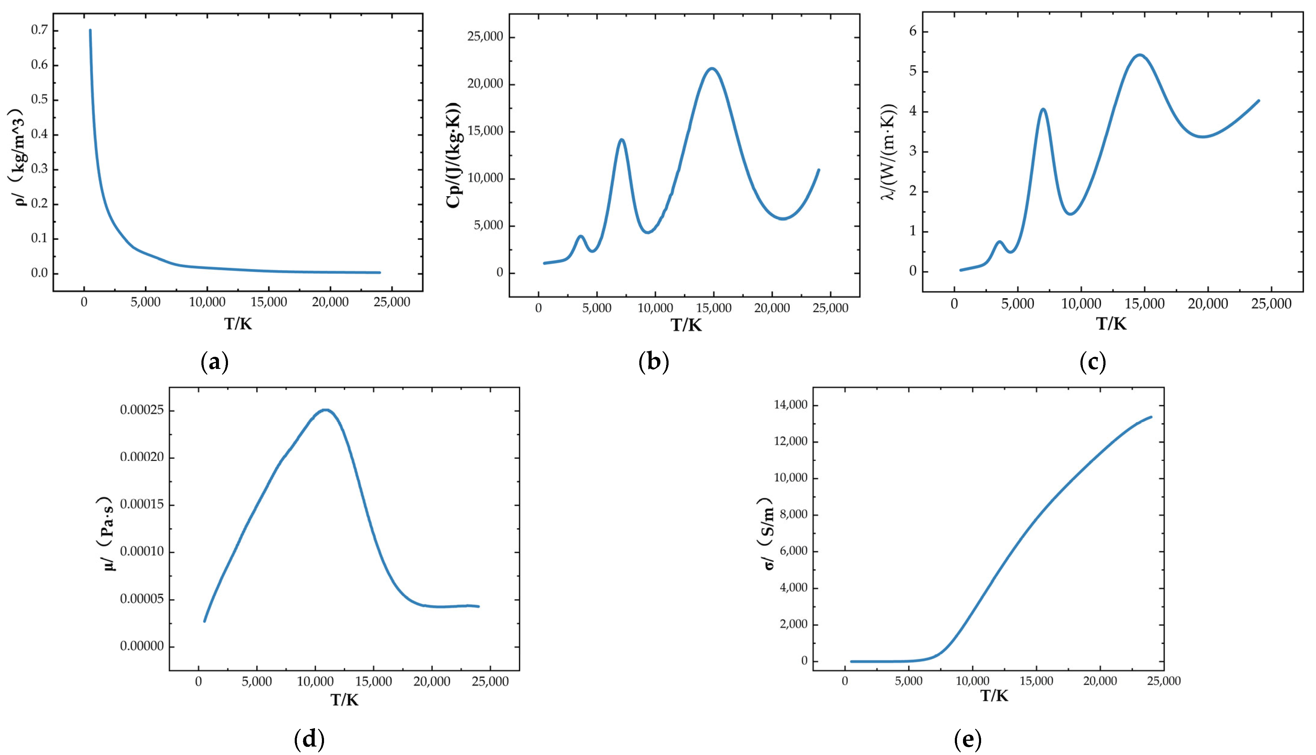
In this study, the geometric model of the pantograph–catenary system was established using the COMSOL finite-element software, as shown in Figure 3. The contact wire was assigned a lower radius of 6.45 mm, and the pantograph–catenary gap was set to 6 mm. The contact wire was modeled as a copper–tin alloy conductor, while three types of pantograph sliders were incorporated: pure-carbon, copper-impregnated carbon, and copper-based powder-metallurgy. The parameters of each slider are listed in Table 1. The physical properties of air within the solution domain—namely density, specific heat at constant pressure, dynamic viscosity, thermal conductivity, and electrical conductivity—were defined as temperature-dependent variables. Their variation with temperature was depicted in Figure 4 [15].

3. Governing Equations

In this study, a pantograph–catenary arc simulation model was established based on heat-transfer theory. The governing equations were derived by coupling the physical fields associated with the arc, and the solutions yielded the distributions of arc temperature, electric field, and current density.

3.1. MHD Model

During the model development, the conservation equations of mass, momentum, and energy were strictly followed [16,17]. The MHD model couples the three major conservation equations of fluid dynamics with electromagnetic fields. In the momentum and energy terms of the arc flow field equations, Joule heating (generated by the current) and the Lorentz force (induced by the magnetic field) were required, as shown in Figure 5 [18].
In the figure, the physical quantities were defined as follows: ρ (kg/m3) denoted the density, v (m/s) the velocity vector, T (K) the temperature, λ (W/(m·K)) the thermal conductivity, and Cp (J/(kg·K)) the specific heat capacity. The electromagnetic-related quantities were given as σ (S/m) for the electrical conductivity, J (A/m2) for the current density, ϕ (V) for the electric potential, A for the magnetic vector potential, μ0 (H/m) for the vacuum permeability, and B (T) for the magnetic flux density of the arc. In addition, r (m) is the vertical distance to the contact wire, and I is the identity matrix.
The electromagnetic–thermal–fluid boundary conditions of the model are shown in Figure 6 [19,20].

3.2. Surface Ablation Model

Arc erosion was recognized as a complex coupled physical process involving heating, melting, evaporation, and even splashing of molten liquid. To efficiently evaluate the total mass loss rate of the material while maintaining computational efficiency, a surface ablation model based on energy conservation was adopted in this study The core assumption of the model was that once the surface temperature of the material reached a critical ablation temperature—typically close to the sublimation or boiling point of the material—the net heat flux acting on the surface would be entirely utilized for phase change ablation, while the surface temperature remained near this critical value.
On the strip surface, the effective heat flux used for heating and ablating the material, denoted as qa, was defined by the following equation:
q a = h a ( T T 0 )
Equation (1) essentially described the rate at which arc energy was input to the material surface. When T0 was below the material’s critical ablation temperature, qa was primarily used for the solid-state heating of the material. When T0 reached and attempted to exceed this temperature, the ablation process was activated. The excess energy was then utilized for mass loss, thereby dynamically constraining T0 near the critical ablation temperature.
Upon initiation of the ablation process, the material ablation rate was given by the following:
v a = q a / ρ H s
where ρ was defined as the material density and Hs as the sublimation latent heat.

4. Model Validity Verification

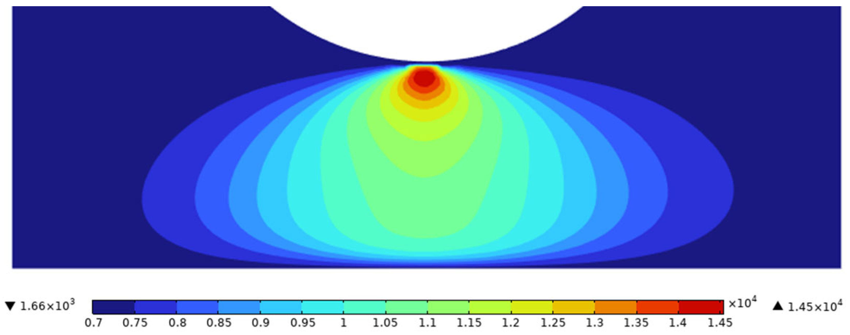
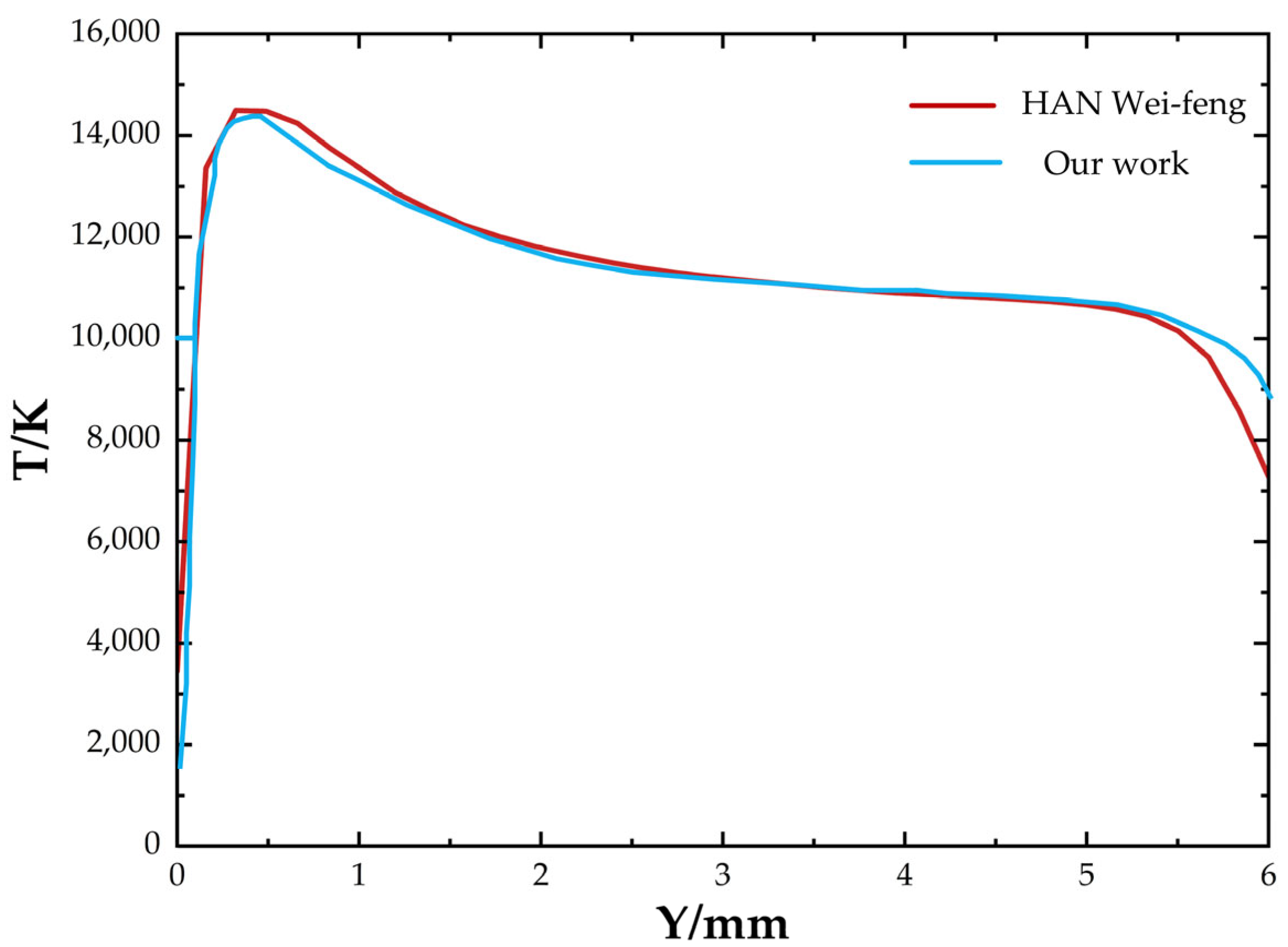
Prior to the investigation of the pantograph–catenary arc, a preliminary validation of the method and approach was required. A geometric model identical to that in Reference [21] was constructed, and the simulation results were compared with the data from the literature. The comparison results are presented in Figure 7 and Figure 8. Good agreement was observed between the obtained current density distribution and the results reported in Reference [21]. These findings confirmed the feasibility of the numerical calculations performed using the method and approach proposed in this study.

5. Simulation and Results Analysis

The high-temperature characteristics of the pantograph–catenary arc can cause ablation effects on the surface materials of the arc system, potentially leading to damage of the pantograph–catenary system components, which in turn may affect the safe operation of the vehicle [22]. Therefore, in order to understand the ablation phenomena occurring in the pantograph–catenary system during these processes, it was necessary to simulate and analyze the temperature distribution of the arc, as well as investigate various factors influencing arc-induced wear on the collector strip. An arc model was established using the COMSOL finite element software, where simulations were conducted to examine the effects of the pantograph–catenary distance and collector strip material on arc ablation.

5.1. Boundary Condition Settings

The distribution characteristics of various indices of the pantograph–catenary arc were studied. In the simulation model, the collector strip material was copper-impregnated carbon, and the contact wire was made of copper-tin alloy. According to the statistical analysis of the operation data of the 50 Hz, 2 × 27.5 kV, 20.5 km AT-fed high-speed railway line from Beijing, China, to Yizhuang [23]. Therefore, in this study, 200 A and the pantograph–catenary gap set at 6 mm were selected as representative working conditions for analysis.
The finite element software was utilized to set the boundary conditions of various physical fields and the material properties parameters and to calculate the arc temperature distribution. The results are shown in Figure 9. As shown in Figure 9a, the highest temperature of the arc column reached 16,800 K, and the plasma radius contracted away from the two poles. A centerline, labeled as AB, was drawn along the arc in Figure 9a to observe the temperature distribution across the cross-sectional area, with the results shown in Figure 9b. It can be observed that the highest temperature of the arc occurred near the contact wire. As the distance from the hotspot increased, the temperature dropped sharply. Figure 9c shows the temperature distribution of the catenary wire, with the maximum surface temperature reaching approximately 6930 K. Figure 9d presents the temperature distribution of the pantograph collector strip, with the highest temperature reaching 7170 K. It can be observed that the internal temperature distribution of the collector strip under the arc’s influence follows a similar trend to the contact wire, with the highest surface temperature at the point of contact with the arc and the temperature gradually decreasing in the direction away from the arc contact point.

5.2. Effects of Pantograph–Catenary Distance and Collector Strip Material on Arc Temperature Distribution

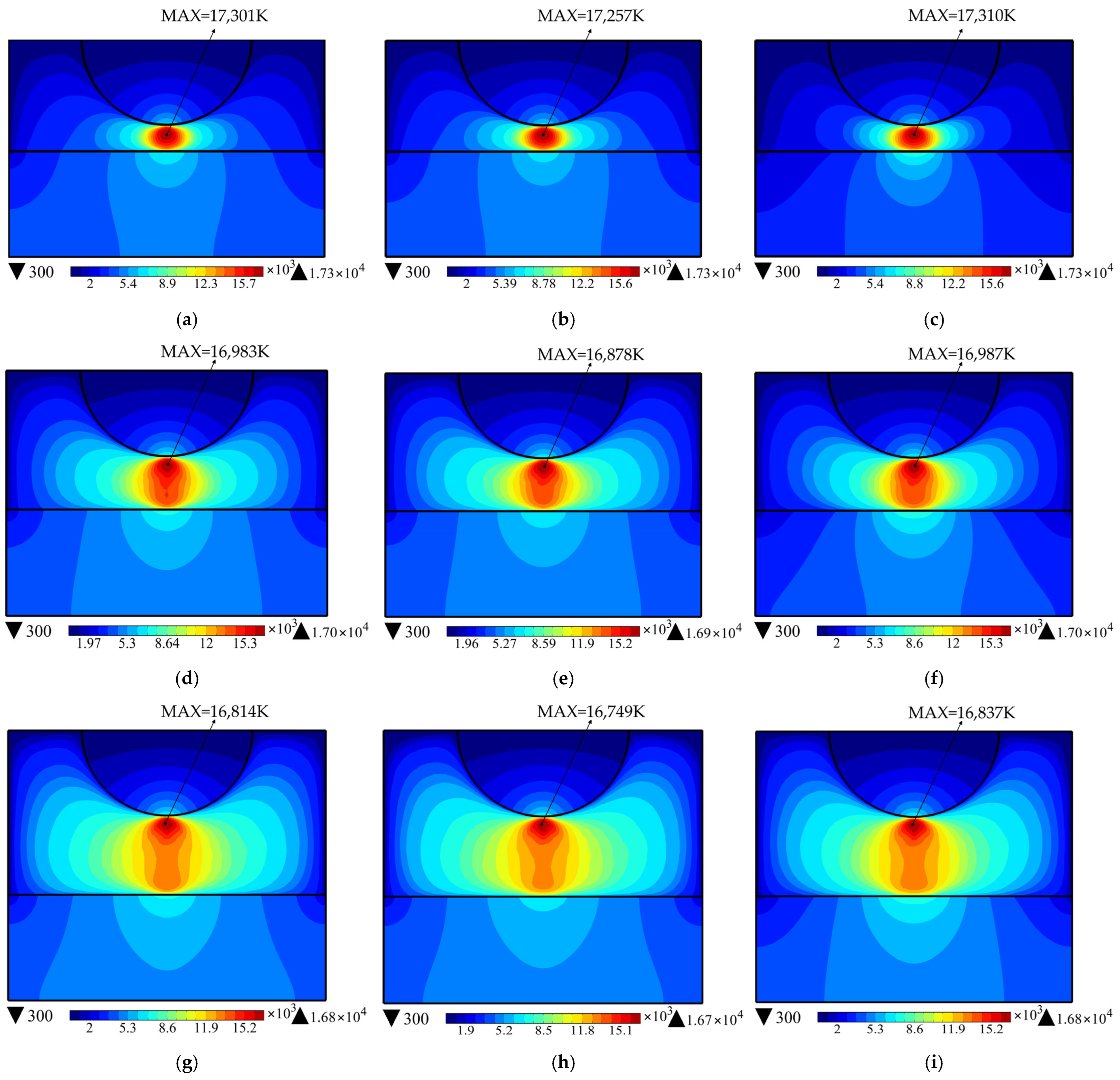
In the simulation software, with the initial conditions unchanged, calculations were performed for slider materials, including a copper-based powder metallurgy slider, a pure carbon slider, and a copper-impregnated carbon slider. The resulting arc temperature distribution of the pantograph–catenary system at distances of 2 mm, 4 mm, and 6 mm between the pantograph and catenary is shown in Figure 10.
The temperature distribution of the pantograph–catenary arc showed that when the slider material remained constant, the shape of the arc stretched as the pantograph–catenary gap increased, transforming from an elliptical shape to a spindle shape. The highest temperatures at both the arc center and the slider surface gradually decreased. When the pantograph–catenary gap remained fixed, changes in slider material led to slight variations in the maximum arc temperature. The copper-impregnated carbon slider exhibited the highest temperature, followed by the copper-based powder metallurgy slider, with the pure carbon slider showing the lowest temperature. For the slider surface temperature, the copper-impregnated carbon slider had the highest temperature, followed by the copper-based powder metallurgy slider, and the pure carbon slider had the lowest, as shown in Figure 11. This variation is related to the thermal conductivity of the slider materials. The copper-impregnated carbon slider, having lower thermal conductivity, slowed the rate of heat conduction within the slider. As a result, the heat generated by the arc on the slider surface could not diffuse efficiently, which confined the high temperature to a smaller area. This also affected the arc temperature distribution, causing the arc column near the slider to contract.

5.3. Effect of Different Slider Materials on Slider Ablation

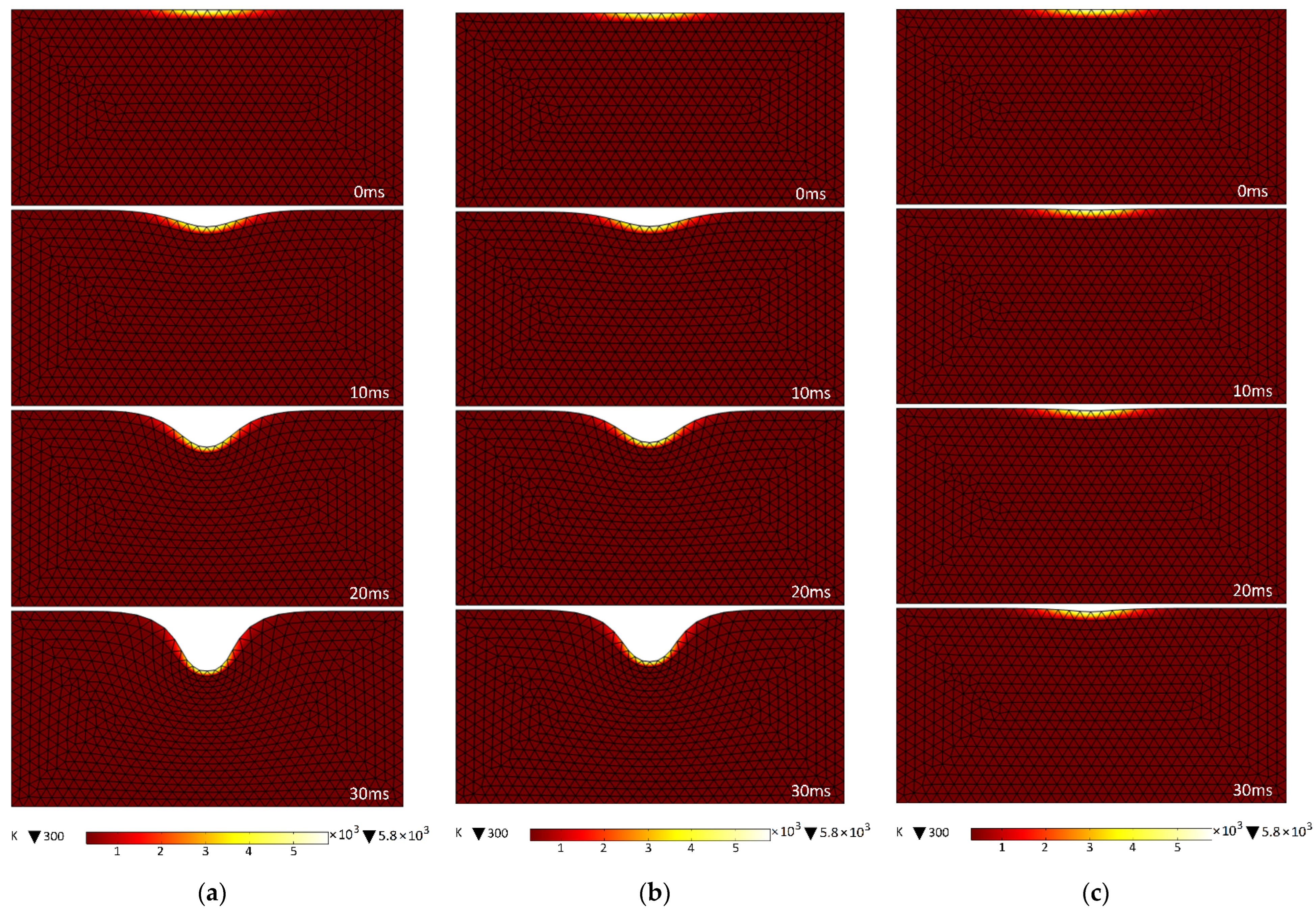
In the simulation software, the arc duration was set to 30 ms [24], and the pantograph–catenary gap was adjusted to 6 mm. The resulting molten pool formation due to arc ablation on the slider was obtained for slider materials, including copper-based powder metallurgy slider, pure carbon slider, and copper-impregnated carbon slider, as shown in Figure 12.
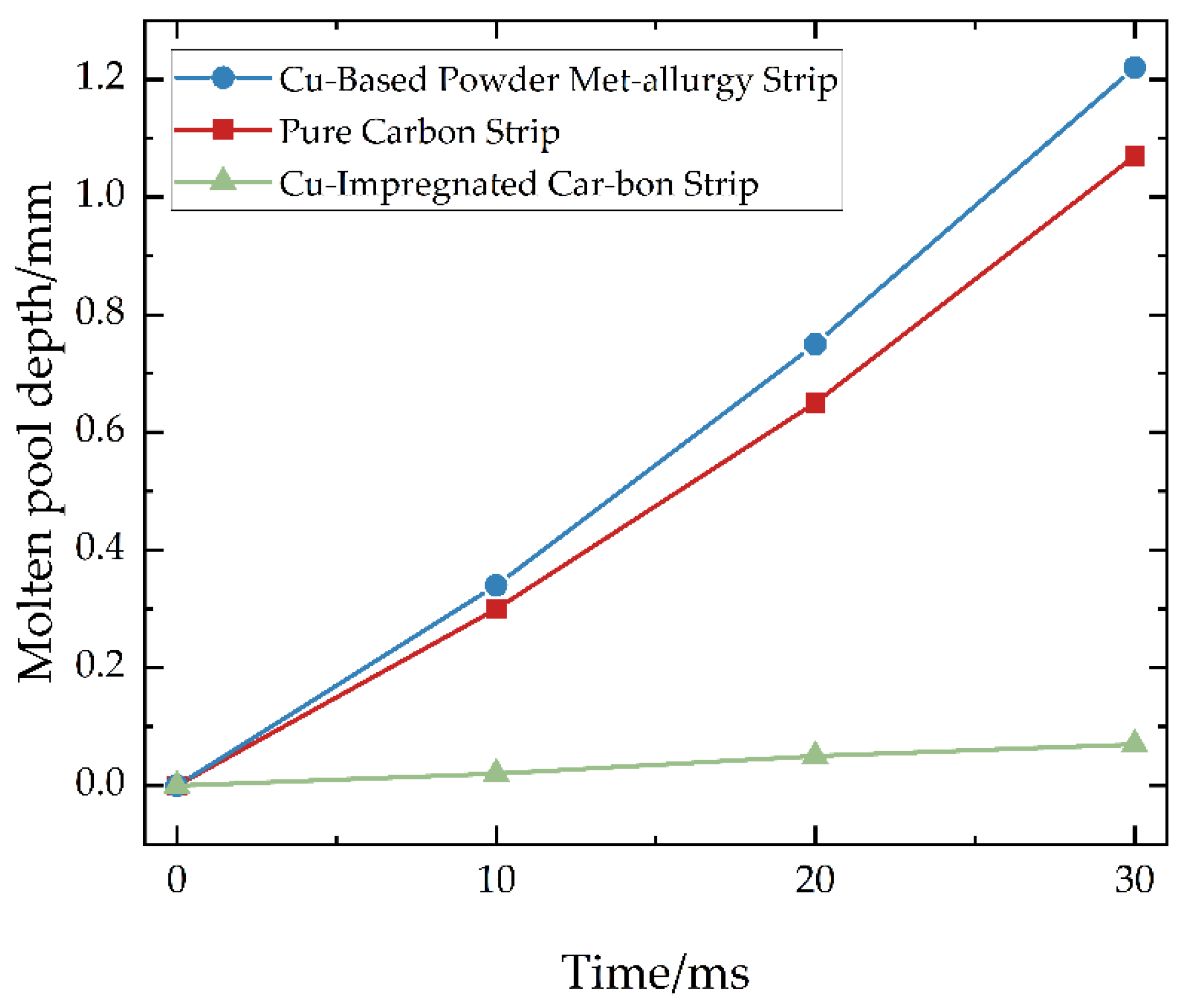
After evaporation and sublimation losses, an ablation molten pool pit was formed on the surface of the slider. Significant differences in the molten pool formation domain were observed for different materials, which can be attributed to their varying latent heat of sublimation. From the molten pool formation images, it was observed that, over time, arc ablation caused the formation of molten pools on the slider surface. The variation in the depth of the surface molten pool for different materials is summarized in Figure 13. Under the same conditions, the copper-impregnated carbon slider exhibited the best ablation resistance, with a molten pool depth of 0.07 mm at an arc duration of 30 ms. The pure carbon slider followed, with a molten pool depth of 1.07 mm at the same arc duration. The copper-based powder metallurgy slider showed the worst ablation resistance, with a molten pool depth of 1.22 mm at an arc duration of 30 ms.

5.4. Effect of Latent Heat of Sublimation on Slider Ablation

The latent heat of sublimation was defined as the amount of heat absorbed or released per unit mass when a substance changed directly from the solid state to the gaseous state. The factors influencing the latent heat of sublimation mainly include the chemical composition of the material, the purity of the material, the temperature and pressure conditions, and the manufacturing process. Therefore, by adjusting the chemical composition, purity, environmental conditions, and processing methods, the latent heat of sublimation could be modified to some extent. With other physical parameters of the contact material kept constant, the effect of the latent heat of sublimation on the molten pool formed on the slider surface was investigated. It was assumed that the latent heat of sublimation of the slider material gradually increased [25]. When the values were set to 6 × 10⁶, 11 × 106, 16 × 106, 21 × 106, 26 × 106, and 31 × 106 J/kg, the calculated maximum surface temperatures of the slider were obtained, as shown in Figure 14.
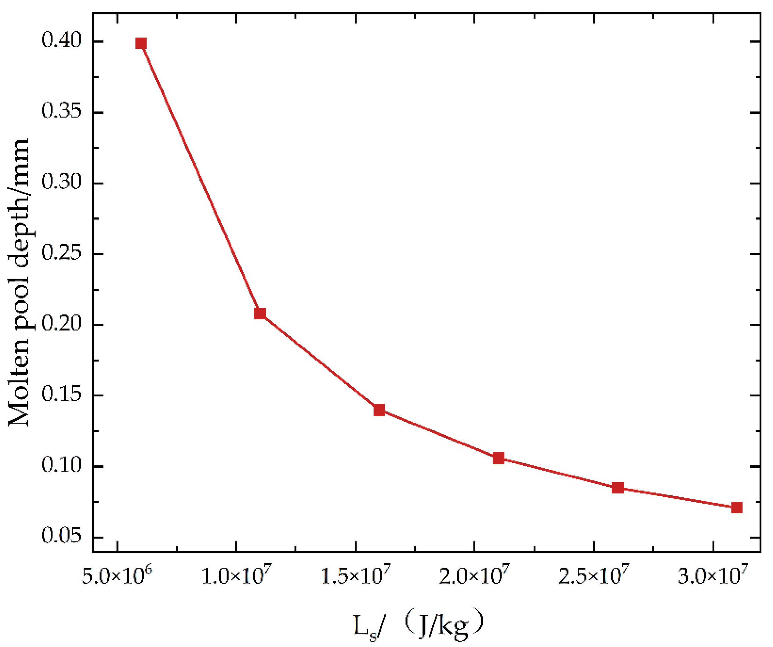
As shown in Figure 15, it was observed that with the increase in latent heat of sublimation, more heat was required for the transition of the slider material from the solid state to the gaseous state, which reduced the depth of the molten pool on the slider surface. When the latent heat of sublimation of the slider material increased from 6 × 10⁶ J/kg to 31 × 106 J/kg, the molten pool depth was reduced to one quarter of its initial value. Therefore, it was demonstrated that an increase in the latent heat of sublimation significantly enhanced the ablation resistance of the material.

6. Conclusions

The pantograph–catenary arc in electrified railway systems induces an ablation effect on the pantograph slider. To reveal the mechanism of arc ablation, reduce the losses in the pantograph–catenary system, and ultimately extend its service life, an MHD simulation model of the pantograph–catenary arc was established using COMSOL 6.2 finite element software. This model was used to solve the arc temperature field and generate arc temperature distribution maps and slider ablation effect images. The related image data were analyzed to investigate the effects of pantograph–catenary gap and slider materials on the slider under arc ablation conditions.
The following conclusions were drawn from the results:
(1)
The simulation revealed the symmetric distribution characteristic of the pantograph–catenary arc temperature, with the highest arc column temperature reaching 16,800 K, peaking near the catenary. The maximum slider surface temperature was 7170 K, and the high temperature caused material loss and changes in the surface morphology. These findings demonstrated that the high temperatures of the arc had a significant ablation effect on the material, providing key insights for material optimization design.
(2)
As the pantograph–catenary gap increased, the shape of the arc transformed from an elliptical to a spindle shape, and the highest temperatures at both the arc center and the slider surface decreased. The slider material had a significant impact on the arc and slider surface temperatures. The copper-impregnated carbon slider exhibited the highest temperature, followed by the copper-based powder metallurgy slider, and the pure carbon slider showed the lowest temperature. This was due to the lower thermal conductivity of the copper-impregnated carbon slider, which caused heat to accumulate on the surface and hinder its diffusion, resulting in a concentration of high-temperature areas. It also caused the arc column near the slider to contract.
(3)
The ablation resistance of different slider materials under arc ablation showed significant differences. The copper-impregnated carbon slider had the best ablation resistance, with a molten pool depth of only 0.07 mm at an arc duration of 30 ms. The pure carbon slider showed a molten pool depth of 1.07 mm, while the copper-based powder metallurgy slider exhibited the poorest ablation resistance, with a molten pool depth of 1.22 mm. Therefore, the latent heat of sublimation was found to be a determining factor in ablation resistance.
(4)
As the latent heat of sublimation of the material increased from 6 × 10⁶ J/kg to 31 × 106 J/kg, the molten pool depth on the slider surface was reduced to a quarter of its original value. By adjusting the chemical composition, purity, environmental conditions, and processing techniques, the latent heat of sublimation could be effectively increased, thereby reducing the degree of ablation on the slider surface and significantly improving the material’s ablation resistance.
This study systematically analyzed the temperature distribution characteristics of the pantograph–catenary arc and its ablation effect on slider materials, revealing the influence of pantograph–catenary gap, slider material, and latent heat of sublimation on arc ablation behavior. The results indicated that optimizing the latent heat of sublimation of the slider material is key to improving its ablation resistance. Future studies could further explore new composite materials and surface treatment technologies to enhance the durability of the slider in arc environments, providing more reliable material solutions for the safe operation of pantograph–catenary systems.

7. Discussion and Prospect

This study establishes a macro-scale simulation model. In actual operation, the ablation of the pantograph strip is the cumulative result of thousands of separation events. Variations in the surface roughness of both the pantograph strip and the contact wire significantly influence the thermal flux distribution and heat dissipation efficiency at the contact point. This important micro-scale physical mechanism represents a current limitation of our model. Integrating it into the existing framework will be a key focus of future research, aiming to more accurately quantify the cumulative ablation effect under repeated separation.

Author Contributions

Conceptualization, M.L. and R.T.; methodology, R.T. and S.-J.W.; software, S.-J.W.; validation, R.T. and S.-J.W.; investigation, J.L.; writing—original draft preparation, S.-J.W.; writing—review and editing, R.T. and S.-J.W.; visualization, R.T. and S.-J.W.; funding acquisition, M.L. and R.T. All authors have read and agreed to the published version of the manuscript.

Funding

This research was funded by the National Natural Science Foundation of China (Nos. 72467026 and 62361037); the Innovation Fund for University Teachers of the Education Department of Gansu Province (Nos. 2023A-034 and 2024CXPT-11); and the “Innovation Star” Program for Excellent Graduate Students of Gansu Province (No. 2027CXZX-687).

Data Availability Statement

The original contributions presented in this study are included in the article. Further inquiries can be directed to the corresponding author.

Conflicts of Interest

Author Jie Li was employed by the company CRRC Nanjing Puzhen Co., Ltd. The remaining authors declare that the research was conducted in the absence of any commercial or financial relationships that could be construed as a potential conflict of interest.

References

  1. Gao, Z.B.; Wu, G.N.; Lu, W. Research review of arc phenomenon between pantograph and catenary in high-speed electrified railway. High Volt. Appar. 2009, 47, 104–108. [Google Scholar]
  2. Guo, J.F.; Ke, Z.T.; Liu, J.Z. Identification of railway pantograph-catenary contact force based on data modeling. China Railw. Sci. 2021, 42, 147–174. [Google Scholar]
  3. Gao, S.B.; Liu, Z.G.; Yang, J. Research prospect for overhead contact system of 400 km/h high-speed railway. High Speed Railw. Technol. 2021, 12, 11–16. [Google Scholar]
  4. Huang, M.; Yang, B.; Liao, Z.; Lü, P.; Xiao, S.; Yang, G.; Zhu, T. Research on wear of pantograph slide plate: A review. J. Mech. Eng. 2025, 61, 193–213. [Google Scholar]
  5. Liu, Y.N.; Li, X.Q.; Wang, Q.F. Pantograph catenary off-line overvoltage characteristics of emu. Insul. Surge Arresters 2023, 2, 55–61. [Google Scholar]
  6. Huang, M.; Yang, B.; Xiao, S.N. Microscopic investigation on current-carrying wear on surface of pantograph carbon slide surface of metro train. Electr. Drive Locomot. 2022, 4, 133–139. [Google Scholar]
  7. Zhou, H.; Duan, F.; Liu, Z. Study on electric spark discharge between pantograph and catenary in electrified railway. IET Electr. Syst. Transp. 2022, 12, 128–142. [Google Scholar] [CrossRef]
  8. Tang, Y.T. Research on Model Characteristics and Emi of Pantograph-Catenary Arc of the High Speed Train. Master’s Thesis, Southwest Jiaotong University, Chengdu, China, 2021. [Google Scholar]
  9. Xiao, S.; Cao, Y.; Wu, G.N. Influence mechanism and suppression methodologies of the overvoltage of high-speed railway on the vehicle-mounted traction power supply system: Systematic review. Proc. CSEE 2024, 44, 4682–4702. [Google Scholar]
  10. Gao, G.Q.; Hao, J.; Wei, W.F. Dynamics of pantograph-catenary arc during the pantograph lowering process. IEEE Trans. Plasma Sci. 2016, 44, 2717–2723. [Google Scholar] [CrossRef]
  11. Ma, H.; Tian, E.; Yan, T. Study on the influence of different magnetic fields on vacuum arc based on COMSOL. J. Phys. Conf. Ser. 2019, 1486, 062038. [Google Scholar] [CrossRef]
  12. Yu, X.Y.; Song, M.J.; Wang, Z. Simulation and verification of effect of arc duration on arc temperature based on COMSOL. Machines 2023, 11, 2–13. [Google Scholar] [CrossRef]
  13. Ma, Q.; Rong, M.Z.; Anthony, B.M. Simulation and experimental research on air arc movement characteristics in low-voltage circuit breaker considering electrodes erosion. Proc. CSEE 2009, 29, 117–120. [Google Scholar]
  14. Shi, Y.D.; Zhou, Y.; Gao, G.Q. Interaction mechanism between copper-impregnated carbon materials and arc. Proc. CSEE 2018, 44, 3872–3979. [Google Scholar]
  15. Gleizes, A.; Gonzalez, J.J.; Freton, P. Thermal plasma modelling. J. Phys. D Appl. Phys. 2007, 38, R153. [Google Scholar] [CrossRef]
  16. Zhu, G.; Wu, G.; Han, W.; Gao, G.; Liu, X. Simulation and analysis on steady state characteristics of pantograph arc during static lifting and lifting of high-speed train. China Railw. Soc. 2016, 38, 42–47.22. [Google Scholar]
  17. Xu, Z.; Gao, G.; Wei, W. Characteristics of pantograph-catenary arc under low air pressure and strong airflow. High Volt. 2022, 7, 369–381. [Google Scholar] [CrossRef]
  18. Zhu, G.Y.; Gao, G.Q.; Wu, G.N. Modeling pantograph-catenary arcing. Proceedings of the Institution of Mechanical Engineers, Part F. J. Rail Rapid Transit 2016, 230, 1687–1697. [Google Scholar] [CrossRef]
  19. Hsu, K.C.; Etemadi, K.; Pfender, E. Study of the free-burning high-intensity argon arc. J. Appl. Phys. 1983, 74, 1293–1301. [Google Scholar] [CrossRef]
  20. Karetta, F.; Lindmayer, M. Simulation of the gas dynamic and electromagnetic processes in low voltage switching arcs. IEEE Trans. Compon. Packag. Manuf. Technol. Part A 1998, 21, 96–103. [Google Scholar] [CrossRef]
  21. Liu, Z.; Zhou, H.; Huang, K.; Song, Y.; Zheng, Z.; Cheng, Y. Extended black-box model of pantograph-catenary detachment arc considering pantograph-catenary dynamics in electrified railway. IEEE Trans. Ind. Appl. 2018, 55, 776–785. [Google Scholar] [CrossRef]
  22. Wang, W.G.; Wu, G.N.; Gao, G.Q. The pantograph-catenary arc test system for high-speed railways. Tiedao Xuebao/J. China Railw. Soc. 2012, 34, 22–27. [Google Scholar]
  23. Han, W.F.; Gao, G.Q.; Liu, X.R. MHD model of pantograph-catenary arc. J. China Railw. Soc. 2015, 5, 21–26. [Google Scholar]
  24. Xing, L.C.; Zhang, X.D.; Liu, B. Spectroscopy method used in temperature and electron density of pantograph-catenary arc. Spectrosc. Spectr. Anal. 2018, 38, 890–894. [Google Scholar]
  25. Shi, P.A. Effects of latent heat of phase change on dynamic behavior of fluid flow and heat transfer in laser weld pool of beryllium. Hot Work. Technol. 2009, 38, 1–5. [Google Scholar]
Figure 1. Multi-physics coupling mechanism of the pantograph–catenary arc ablation process.
Infrastructures 10 00276 g001
Figure 2. This is a figure. Schemes follow the same formatting.
Infrastructures 10 00276 g002
Figure 3. Pantograph–catenary arc: (a) geometric shape; (b) simplified model.
Infrastructures 10 00276 g003
Figure 4. Variation curves of air parameters with temperature: (a) density; (b) specific heat capacity at constant pressure; (c) thermal conductivity; (d) dynamic viscosity; (e) electrical conductivity.
Infrastructures 10 00276 g004
Figure 5. Schematic of the governing equations for MHD.
Infrastructures 10 00276 g005
Figure 6. Overall boundary condition setting.
Infrastructures 10 00276 g006
Figure 7. Arc simulation reproduction.
Infrastructures 10 00276 g007
Figure 8. Temperature comparison at the center of the arc.
Infrastructures 10 00276 g008
Figure 9. Temperature distribution: (a) arc; (b) central axis; (c) contact wire; (d) pantograph strip.
Infrastructures 10 00276 g009
Figure 10. Temperature distribution of pantograph strips under different pantograph–catenary distances: copper-based powder metallurgy strip—(a) 2 mm, (d) 4 mm, (g) 6 mm; pure carbon strip—(b) 2 mm, (e) 4 mm, (h) 6 mm; copper-impregnated carbon strip—(c) 2 mm, (f) 4 mm, (i) 6 mm.
Infrastructures 10 00276 g010
Figure 11. Surface temperature distribution curves of the pantograph strip under different pantograph–catenary distances: (a) 2 mm, (b) 4 mm, (c) 6 mm.
Infrastructures 10 00276 g011
Figure 12. Formation of the molten pool on pantograph strips: (a) copper-based powder metallurgy strip; (b) pure carbon strip; (c) copper-impregnated carbon strip.
Infrastructures 10 00276 g012
Figure 13. Variation of surface molten pool depth for different materials.
Infrastructures 10 00276 g013
Figure 14. Formation of the surface molten pool at 30 ms under different sublimation latent heats.
Infrastructures 10 00276 g014
Figure 15. Relationship between surface molten pool depth and sublimation latent heat.
Infrastructures 10 00276 g015
Table 1. Material parameters of contact wire and pantograph strip.
Physical ParametersCu–Sn Alloy ConductorCu-Based Powder Metallurgy StripPure Carbon StripCu-Impregnated Carbon Strip
Density/(kg·m−3)9020810024002320
Specific Heat Capacity/(J·kg−1·K−1)384376710478
Thermal Conductivity/(W·m−1·K−1)398801516
Electrical Resistivity/(μΩ·m)0.0240.353.810
Sublimation Latent Heat/(J·kg−1)-4.71 × 1063.26 × 1073.1 × 107
Disclaimer/Publisher’s Note: The statements, opinions and data contained in all publications are solely those of the individual author(s) and contributor(s) and not of MDPI and/or the editor(s). MDPI and/or the editor(s) disclaim responsibility for any injury to people or property resulting from any ideas, methods, instructions or products referred to in the content.