Article

Dynamic Response and Design Optimization of Box Girder Bridge with Corrugated Steel Webs Subjected to Blast Loads

1
China Construction Sixth Engineering Bureau Co., Ltd., Tianjin 300171, China
2
School of Civil Engineering, Tianjin University, Tianjin 300354, China
3
School of Mechanical Engineering, Tianjin University, Tianjin 300354, China
*
Author to whom correspondence should be addressed.
Infrastructures 2025, 10(10), 256; https://doi.org/10.3390/infrastructures10100256
Submission received: 13 August 2025 / Revised: 19 September 2025 / Accepted: 20 September 2025 / Published: 24 September 2025

Abstract

Throughout the service life, bridge structures may face blast hazards from military conflicts, terrorist attacks, and accidental explosions. Dynamic responses and damage modes of box girder bridges with corrugated steel webs under blast loading remain scarce. This study investigates the dynamic response and optimal design of box girder bridges with corrugated steel webs under blast loading. A box girder bridge model with corrugated steel webs is established through the software LS-DYNA, and the dynamic response of the bridge model subjected to blast loads is studied. Parametric studies are conducted to evaluate the effects of key geometric parameters, including the folding angle, height–span ratio, and dip angle of corrugated steel webs, on the blast-resistance performance of the bridge. The results indicate that a folding angle of 55° provides optimal blast resistance by balancing local stiffness and stress concentration. The 3.0 m height of corrugated steel webs maximizes the energy absorption capacity of corrugated steel webs while minimizing mid-span residual deflection. A dip angle of 85° ensures effective deformation constraint and load transfer, reducing damage in both the upper and bottom bridge decks. This study highlights the critical role of corrugated steel web geometry in enhancing blast resistance and provides practical guidelines for optimizing the design of box girder bridges with corrugated steel webs under extreme loading conditions.

1. Introduction

As an important component of transportation systems, bridges are widely used in modern life. The nonlinear behavior and damage modes of ordinary reinforced concrete (RC) bridges under various disasters such as earthquakes, corrosion, etc., have been extensively studied [1,2,3]. In 1975, a box girder bridge with corrugated steel webs (CSWs) was first proposed by Pierre Thivans [4]. Compared with traditional concrete box girder bridges, box girder bridges with CSWs have advantages such as having excellent mechanical properties, efficient prestressed concrete flanges, good economic performance, and being environmentally friendly [2]. Throughout their service life, bridge structures face blast hazards from military conflicts, terrorist attacks, and accidental explosions. Research on damage modes and dynamic responses of box girder bridges with CSWs under blast loading remains scarce.
In recent decades, researchers have conducted extensive research on the performance of box girder bridges with CSWs [5,6,7,8,9] under static loads. In the 1920s, Bergmann and Reissner studied the shear performance of corrugated steel plates. Based on the elastic theory, the rectangular corrugated steel plate was regarded as an orthotropic plate with different bending stiffness in two vertical directions, and the shear buckling load per unit length of corrugated steel plate was derived [10]. M. Elgaaly and H. Lewis found that the shear capacity of CSW beams was entirely controlled by the CSW, and the failure of the steel web was caused by buckling. When the corrugate was dense, the damage of the steel web was controlled by the overall buckling strength [11,12,13]. R. Luo and B. Edlund et al. studied the shear buckling strength of CSW by using a nonlinear finite element method. They found that the geometric parameters of CSWs have a significant impact on the buckling strength. The buckling strength increases with the increase in height, thickness, and folding angle of CSWs [14,15]. E. L. Metwally et al. experimentally studied the flexural performance of CSW beams. The results showed that when the beam section was subjected to bending moment, the longitudinal stress of the CSW was close to zero. The bending moment of the beam section could be regarded as being completely borne by the top and bottom decks of the CSW beam [16].
Blast load is characterized by a short duration and high peak overpressure, which is different from conventional static or dynamic loads [17,18]. The detonation of TNT explosive generates a shock wave that propagates radially, exerting significant impulsive force on structures [19]. Box girder bridges, commonly used in modern highway or railway infrastructure, are particularly vulnerable to blast-induced damage due to their thin-walled and open-section configurations [20,21]. Pan et al. [22] investigated the dynamic performance of three modern types of RC bridges under various blast loads, including a slab-on-girder bridge, a box-girder bridge, and a long-span cable-stayed bridge. The most critical blast-resistant scenarios are identified. Vaghefi and Mobaraki [23] studied the effect of an explosion accident on a concrete bridge deck, and through the numerical method the failure mode of the concrete bridge deck under 1000 kg of TNT was proposed. When subjected to blast load, bridges typically exhibit local deformation and cracking at the web–flange junction, followed by global instability if the blast load exceeds the yield strength and ductility of the material. The dynamic response of the box girder involves complex interactions between bending, shear, and axial forces, which can lead to shear buckling and local buckling under high impulsive load [24,25,26].
The dynamic performance and damage mechanism of composite structures with CSWs have been investigated. Yu et al. [27] investigated the blast resistance of composite structures with CSWs. Deformation characteristics and failure modes and identified key factors influencing blast resistance were analyzed. Moreover, the influence of different angle CSWs on the blast-resistance performance of composite structures has also been studied by Cao et al. [28]. The reflection laws of blast shock waves and CSWs, as well as the damage evolution mechanism of CSWs, have been analyzed, and a damage assessment method was proposed. Although the composite structures with CSWs have been widely used worldwide, current research about box girder bridges with CSWs mainly focuses on the shear buckling, bending resistance, torsion resistance, static load behavior, and dynamic load behavior [8,29,30]. The blast-resistance performance of box girder bridges with CSWs is rarely studied. The unique structure configuration of CSWs, characterized by reduced torsional stiffness and complex stress redistribution, may exacerbate the damage to the bridge caused by blast load. However, the dynamic response and damage laws of structures under explosive loads are still unclear. Therefore, research about the dynamic response of box girder bridges with CSWs subjected to blast load is crucial for ensuring the continuous operation of infrastructure under extreme load conditions.
In this study, the dynamic response and optimal design of box girder bridges with CSWs subjected to blast loading are investigated. The box girder bridge models with CSWs are established through the software LS-DYNA R11.1.0. The effect of folding angle, height–span ratio, and dip angle of CSWs on the blast-resistance performance of the bridge is studied. The force transmission mechanism of CSWs under explosion loading is analyzed, and the optimal design parameters are obtained.

2. Calculation Theory of Box Girder Bridges with CSWs

The axial force of the web plate is not considered in this paper, and it assumes that the web plate can expand and contract freely along the longitudinal bridge direction. Moreover, the vertical bending moment generated by the upper load is completely borne by the concrete top and bottom plates, and the shear force is borne and distributed evenly by the CSWs. This paper conducts force analysis on a box girder bridge with CSWs under bending and torsion states, and relevant design formulas are calculated and derived to provide the theoretical basis for subsequent finite element simulation.

2.1. Stress Calculation of Box Girder Bridge with CSWs

2.1.1. Bending Normal Stress Calculation

A box girder with CSWs under bending state conforms to the plane section assumption [31], and the bending normal stress of the concrete top and bottom plates presents a linear distribution, as shown in Figure 1. c is the distance from the top of the cross-section beam to the neutral axis of the cross-section, b1 and b2 are the widths of the top and bottom plates, t1 and t2 are the thicknesses of the top and bottom plates, t is the thickness of the corrugated steel webs, h1 is the height of the corrugated steel web plate, and h is the height of the box girder.
According to the traditional formula for calculating the bending normal stress of a beam, the longitudinal compression of the beam is ignored and not considered. It is assumed that all parts of the section are in a unidirectional stress state, and Ec is set as the elastic modulus of concrete. According to Hooke’s law [32], normal stress is
σ ( y ) = E ε ( y ) = E c φ y       ( c y c t 1   a n d   h c t 2 y h c ) 0                   ( c t 1 < y < h c t 2 )
According to the principle of static equilibrium, it can be concluded that
N = A σ d A = 0 A y d A = 0   ( c y c t 1   a n d   h c t 2 y h c )
M y = A σ z d A = 0 A y z d A = 0   ( c y c t 1   a n d   h c t 2 y h c )
M z = A σ y d A = M M = E c φ I z φ = M E c I z
I z = A y 2 d A = 0   ( c y c t 1   a n d   h c t 2 y h c )
where EcIz is the bending stiffness of the beam, and Iz is the inertia moment for the principal axis z of the centroid.
Bringing Equation (4) into Equation (1), the normal stress is obtained.
σ ( y ) = M I z y       ( c y c t 1   a n d   h c t 2 y h c ) 0                 ( c t 1 < y < h c t 2 )

2.1.2. Shearing Stress Calculation

Firstly, the shearing stress is calculated based on the straight web beam derivation. Same as ordinary beams, it is assumed that the shearing stress and force are in the same direction and are evenly distributed on the cross-section. The calculation diagram is shown in Figure 2, and it can be obtained.
x = 0 N 2 N 1 d Q * = 0
d Q * = τ b d x = τ b d x
N 1 = A σ 1 d A       N 2 = A σ 2 d A
Substitute Equation (5) into Equation (9), and then substitute Formula (7).
M ( x ) + d M ( x ) I z S Z * M ( x ) I z S Z * τ b d x = 0
The shearing stress formula is obtained.
τ = Q ( S z ) t 2 t I z
where Q is the shearing stress on the cross-section, and Sz is the area moment below the horizontal line of the required shear stress on the cross-section. Szt and Szb are the area moment of total roof and bottom area to neutral axis, respectively.

2.2. Deflection Calculation of Box Girder Bridge with CSWs

2.2.1. Deflection Caused by the Bending Deformation

According to the principle of virtual force, a general formula for calculating the displacement of the truss structure under external load is obtained.
f = f N + f M + f Q = N d u + M d φ + Q γ d s
Because the CSWs do not bear the axial force, and whether it is a traditional concrete box girder or a composite box girder with corrugated steel webs, the deflection caused by the bending deformation is hundreds of times the deflection caused by the axial deformation. Therefore, the axial deformation is very small, and fN is not considered.
The combination of Equations (4) and (12) can be obtained.
f M = M M p E c I z d s
where Ec is the elastic modulus of concrete, Iz is the total area moment of the concrete roof and bottom slab, and M and Mp are the bending moment generated by virtual load and real load.

2.2.2. Deflection Caused by the Shearing Deformation

R. P. Johnson et al. [7] verified the effective shear modulus Ge of corrugated steel webs through laboratory tests; the calculation formation is as follows:
G e = G s ( a w + b w ) / ( a w + c w )
where Ge and Gs are the effective shear modulus and the shear modulus, respectively. aw, bw, and cw are the length of the straight plate section, the length of the inclined plate section, and the horizontal projection length of the inclined plate section of the corrugated steel web, respectively.
The calculation formula of the overall shear stiffness of the box girder with corrugated steel webs is
G A = G e A w
where Aw is the cross-section area of the corrugated steel webs.
Based on the principle of the energy method, the calculation formula of deflection caused by shear deformation in the mid-span of a simply supported beam under uniformly distributed load is obtained.
Q γ p d s = τ d A · γ p d s = d s A τ τ p G d A
where Q and τ are the shear force and shear stress on the micro segment in the virtual state, respectively. τp and γpds are the shear stress in the actual state and the deformation of the micro segment, respectively.
If the shear stress distribution is simplified, it is assumed that the corrugated steel webs bear all the shear force, and it is evenly distributed along the beam height.
f Q = A Q Q p G e A w d s
The calculation formula of elastic deflection caused by the shearing deformation is obtained.
f = M M p E c I z d s + A Q Q p G e A w d s

3. Establishment and Calibration of Numerical Models of Box Girder Bridge with CSWs

3.1. Numerical Model of Box Girder Bridge with CSWs

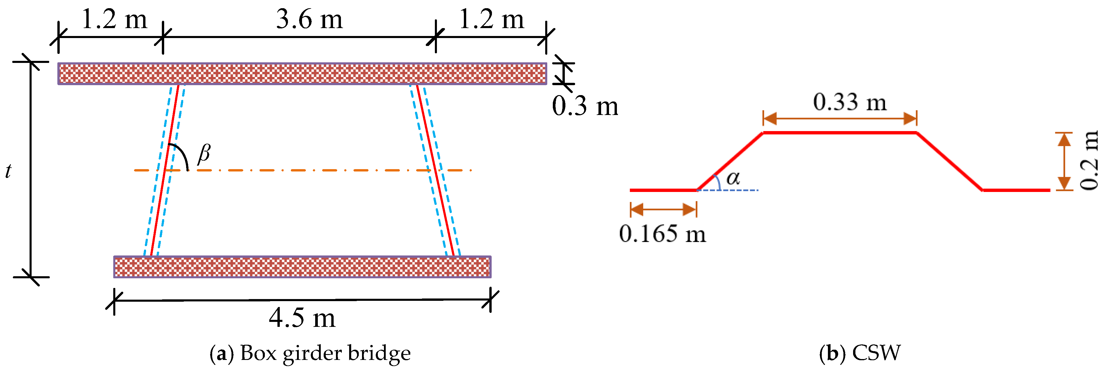
To study the dynamic response of a box girder bridge with CSWs subjected to blast load, the numerical model of a bridge with CSWs, as shown in Figure 3, is established via the software LS-DYNA. The geometric parameters of the bridge and CSW are given in Figure 4. The length of the bridge is 30 m. The semidiameter of the reinforcement is 0.01 m. The distance between the adjacent reinforcements is 0.15 m, and the geometric reinforcement ratio for the bridge is 1.6%, which meets the requirements of Specifications for Seismic Design of Highway Bridges (JTG/T 2231-01—2020) [33]. In the simulation, the material models and contact conditions of the numerical model are defined by the keywords in LS-DYNA. Table 1 gives the keywords used to define the numerical model. The material parameters for the numerical model are given in Table 2. The blast load applied to the numerical model is determined by the keyword *Load_ Blast_ Enhanced in LS-DYNA. According to Standard for blast protection design of civil buildings in China [34], the classification of TNT equivalent for various explosive threats shows that luggage bombs weigh less than 50 kg, while car bombs weigh between 250 and 10,000 kg. Considering China’s strict control over explosives, in this paper, luggage bombs weighing 50 kg are adopted. The blast load is induced by a TNT detonation with a mass of 50 kg and standoff distance of 1.5 m. The coordinates of the TNT detonation are x = 0 m, y = 1.5 m, z = −15 m.
The strain rate effect on the strength of concrete and reinforcement is described by the dynamic increase factor (DIF).
The DIFs for concrete are [35,36]
CDIF = f cd / f cs = 0.0419 ( log ε ˙ d ) + 1.2165 ,   ε ˙ d 30 s 1
CDIF = f cd / f cs = 0.8988 ( log ε ˙ d ) 2 2.8255 ( log ε ˙ d ) + 3.4907 ,   ε ˙ d > 30 s 1
TDIF = f td / f ts = 0.26 ( log ε ˙ d ) + 2.06 ,     ε ˙ d 1 s 1
TDIF = f td / f ts = 2 ( log ε ˙ d ) + 2.06 ,   1 s 1 <   ε ˙ d 2 s 1
TDIF = f td / f ts = 1.44331 ( log ε ˙ d ) + 2.2276 ,   2 s 1 <   ε ˙ d 150 s 1
The DIFs for reinforcement are [37]
DIF = ε ˙ 10 4 η
where η for the yield stress fy in MPa is η f y = 0.074 0.04 f y / 60 , and for the ultimate stress is η f u = 0.019 0.009 f y / 60 .

3.2. Calibration of Numerical Model

In order to investigate the grid sensitivity of the model, a mesh convergence test is conducted by using three mesh sizes of 0.15 m, 0.075 m, and 0.0375 m. The numerical model of a bridge composed of CSWs with folding angle α = 55° and dip angle β = 90° is established. Figure 5 shows the displacement time histories at E1 of bridges with different mesh sizes. As shown, the results obtained from the numerical models with mesh sizes 0.075 m and 0.0375 m are almost identical, whereas the numerical model with a 0.15 m mesh size gives different results. Therefore, the mesh size of 0.075 m is used in the subsequent study.
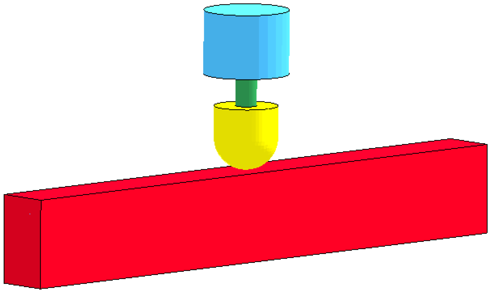
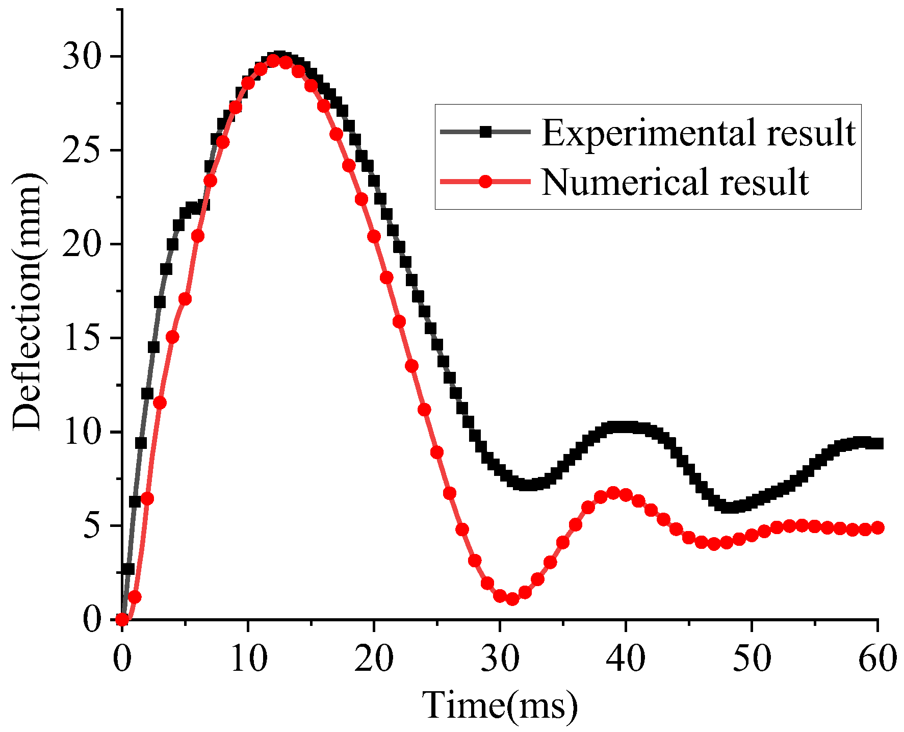
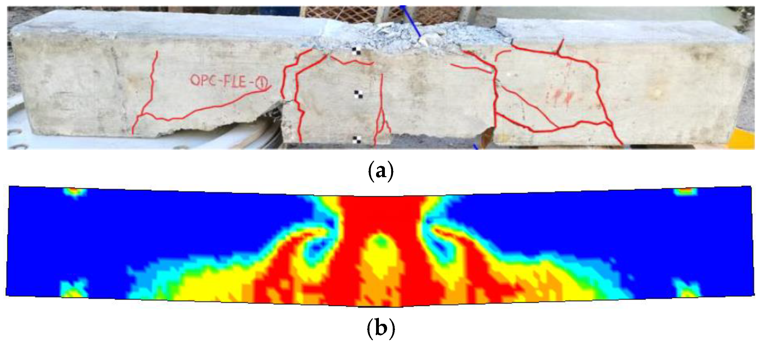
In this study, the test results of concrete beams under drop-weight impact reported in [38] are used to calibrate the numerical model. Figure 6 shows the numerical model of the concrete beam. The material parameters of concrete and reinforcement in the concrete beam are given in Table 2. Figure 7 compares the experimental and numerical results of midspan deflection. Figure 8a,b compare the damage modes of concrete beams subjected to drop-weight impact. The experimental and numerical results, including peak and residual displacement, are listed in Table 3. Experimental and numerical peak displacement are 30.1 mm and 29.2 mm, respectively, and the error is about −3%. But, the error of experimental and numerical residual displacement is about −49%. The reason may be that the material in the numerical model is homogeneous and does not consider the interfacial effects between aggregates. On the other hand, the boundaries in the numerical simulation are ideal boundary conditions, which can cause certain errors between the numerical results and the experimental results. However, the failure modes agree well with the testing results, and the change trend of deflection time–history curves is also consistent. Therefore, the numerical model in this paper can be used for subsequent numerical simulations.

4. Response of Box Girder Bridge with CSWs Subjected to Blast Load

4.1. Effect of Folding Angle of CSW on the Response of Box Girder Bridge

To study the effect of folding angle of CSW on the response of a box girder bridge, the dynamic responses of box girder bridges composed of CSWs with different folding angles are studied via the software LS-DYNA. The numerical models of CSWs with different folding angles (α = 25°, 40°, 55°, 70°, 85°) are established.
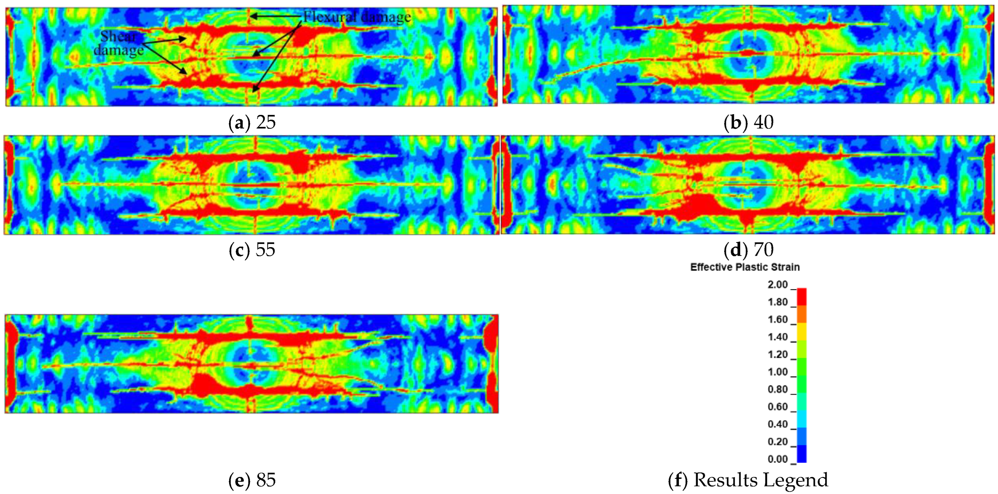
Figure 9 and Figure 10 show the damage modes of box girder bridges composed of various CSWs with different folding angles at t = 11 s. Figure 11 shows the damage modes of CSWs with different folding angles. As shown, the upper deck and bottom deck around the CSWs in the middle of the box girder bridge are severely damaged because of the significant stress concentration at the intersection of the CSW and the bridge deck. As shown in Figure 10, the damage to the bottom deck is more severe as the folding angle of the CSW increases. The local stiffness of the CSW increases with the increase in folding angle. As shown in Figure 11, the CSW with a low folding angle is more severely damaged than that with high folding angle, which means the shear capacity of the CSW increases with the increase in folding angle.
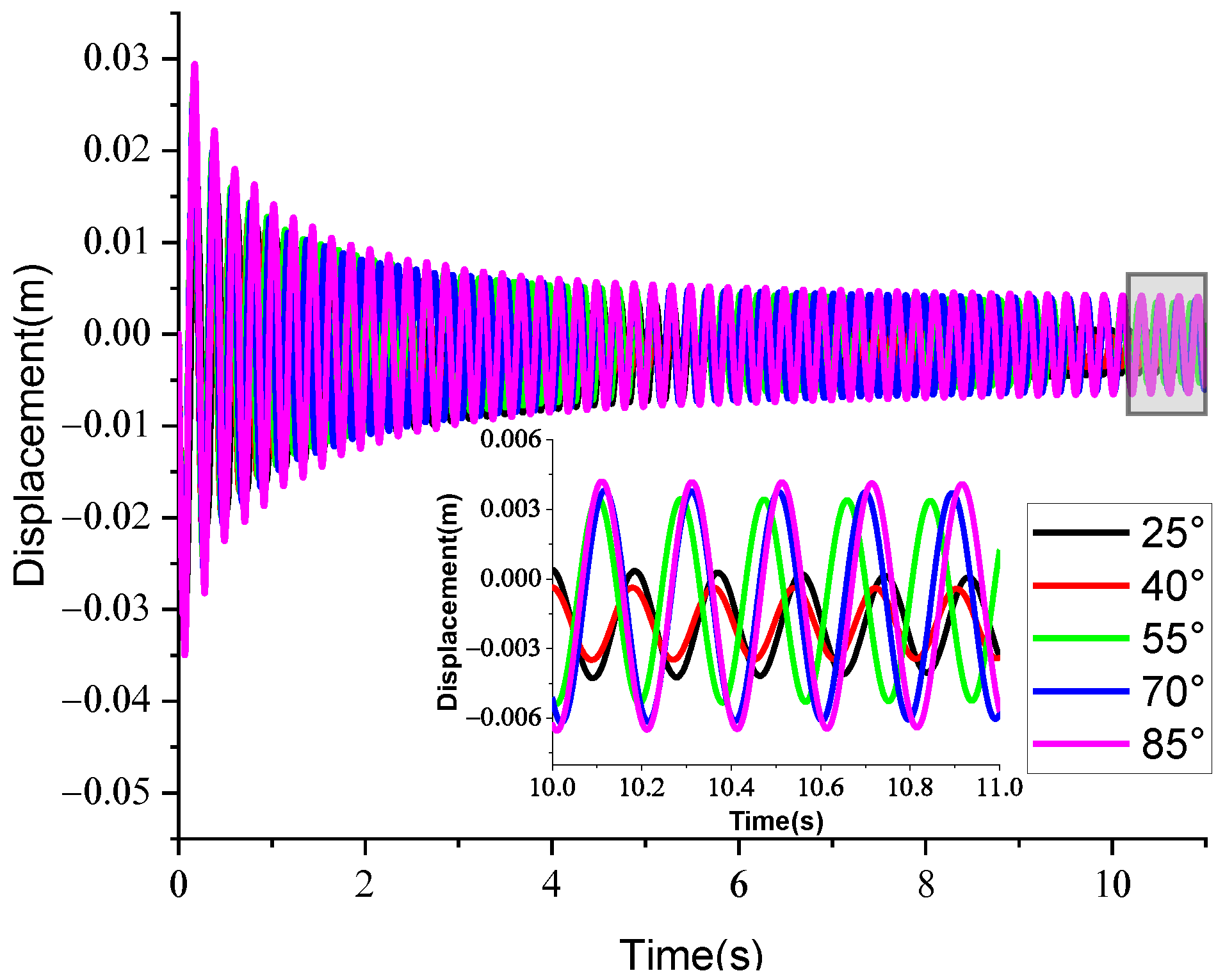
Figure 12 is the midspan deflection time histories of box girder bridges with different folding angles. As shown, the vibration period of box girder bridges with a low folding angle is higher than that with a big folding angle. The maximum and minimum values of midspan deflection of bridges with big folding angle are higher than those composed of CSWs with low folding angles. The cross-sectional stiffness of the bridge is increased with the increase in the folding angle of the CSW, which leads to more effective transmission of blast load to the bottom deck. The residual deflection of box girder bridges with a folding angle of 55° is less than those composed of other folding angles, which indicates the box girder bridge with a folding angle of 55° has better blast-resistance capacity than bridges composed of other folding angles. The blast-resistance performance of box girder bridges is related to the local stiffness of the CSW and the stress concentration at the bridge deck induced by the folding effect of the CSW.

4.2. Effect of Height–Span Ratio on the Response of Bridges with CSWs

Due to the special composition of box girder bridges with CSWs, the blast-resistance performance of bridges with CSWs is affect by the height–span ratio of the bridge. Therefore, the numerical models of bridges with cross-section heights of 2 m, 2.5 m, 3 m, and 3.5 m are established in this study to study the effect of height–span ratio on the dynamic response of box girder bridges with CSWs. In this section, the folding angle of the CSW is α = 55°.
Figure 13 and Figure 14 show the damage modes of bridge upper decks and bottom decks with different height–span ratios at t = 11 s. As shown, the upper deck and bottom deck are both shear damaged around the interface of the CSW and bridge deck because of the stress concentration induced by the CSW. As the height–span ratio increases, the bending stiffness of the CSW decreases, and then the flexural damage around the centerline of the upper deck gradually expands towards the interface of bridge deck and CSW (as shown in Figure 13d). It can also be seen that the damage area of the bottom deck around the interface of CSW and bridge deck decreases with the increase in CSW height.
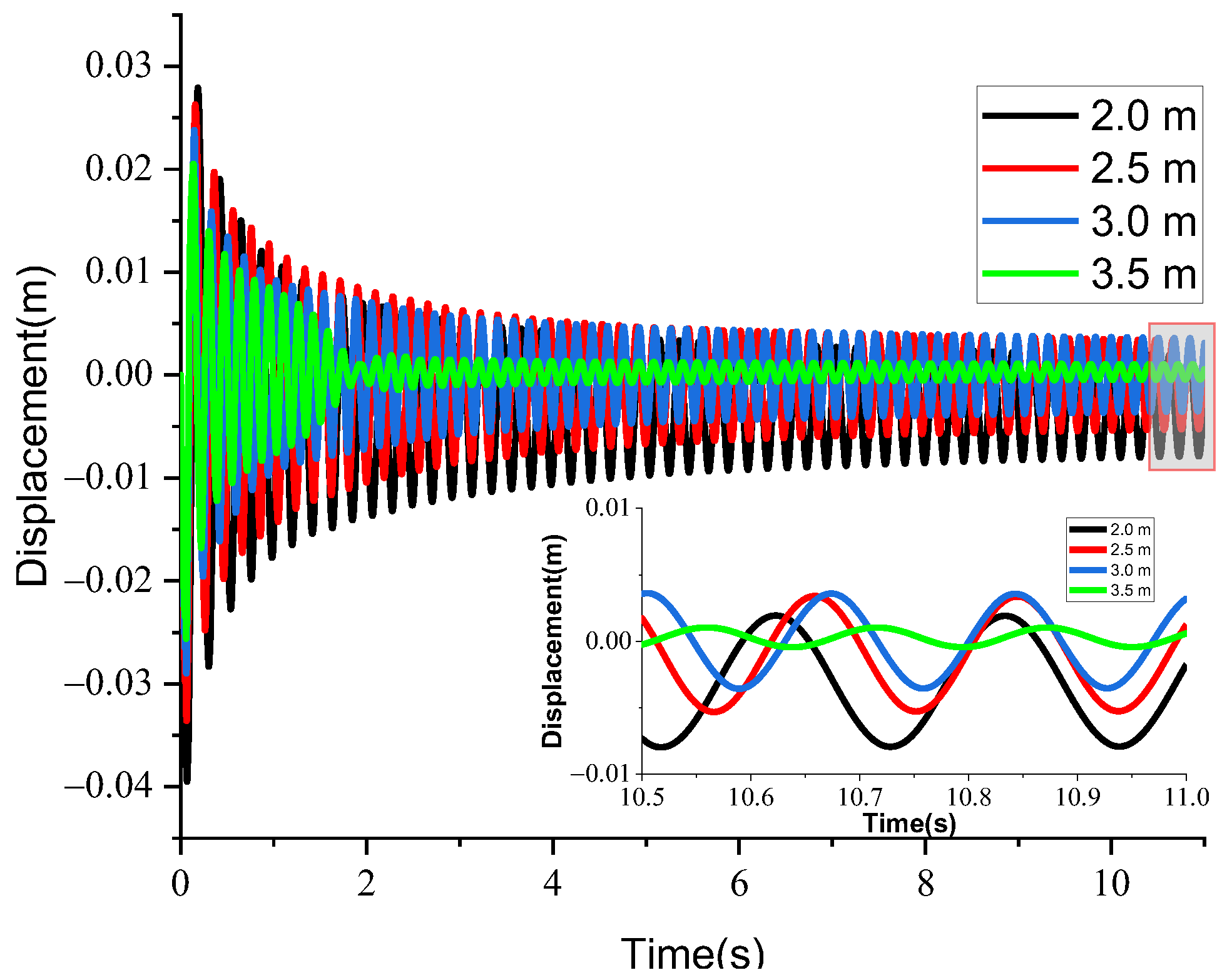
Figure 15 shows the midspan deflection time histories of bridges with different height–span ratios. Figure 16 shows the energy distribution time histories of bridges with different height–span ratios. As shown, the maximum and minimum values of displacement of the bridge bottom deck decrease with the increase in height–span ratio, which means the effect of blast load on the response of the bridge bottom deck decreases with the increase in height–span ratio. This is mainly because the shear stiffness of the bridge cross-section decreases as the height–span ratio of the bridge increases. As shown in Figure 15, the residual deflection of the bridge decreases with the increase of bridge height. However, the energy absorption capacity of the CSW is related to the height–span ratio of the bridge. As shown in Figure 16, the energy absorption capacity of the CSW corresponding to a height of 3.0 m is higher than that of other heights, which means the optimal height of the CSW is 3.0 m in order to improve the blast-resistance performance of a box girder bridge with CSWs.

4.3. Effect of Dip Angle on the Response of Bridges with CSWs

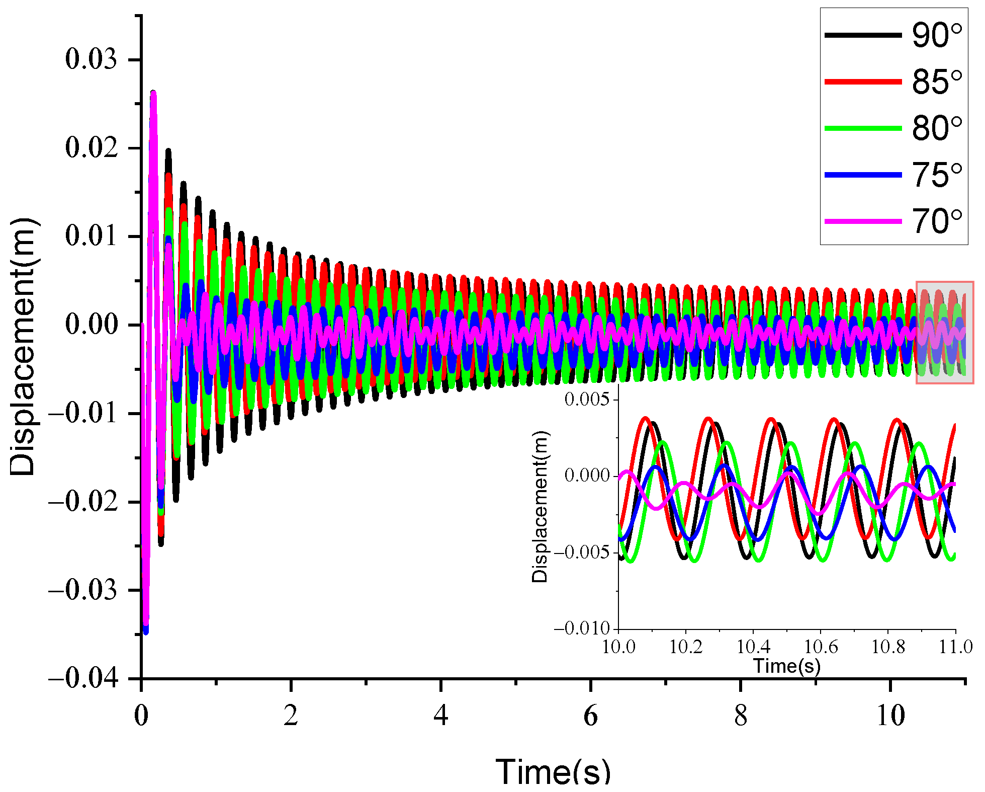
To study the effect of dip angle on the dynamic responses of box girder bridges with CSWs subjected to blast load, the numerical models of bridges with dip angles of 70°, 75°, 80°, 85°, and 90° are established in this study. The folding angle of the CSW is α = 55°. The cross-sectional height of the bridge is 2.5 m.
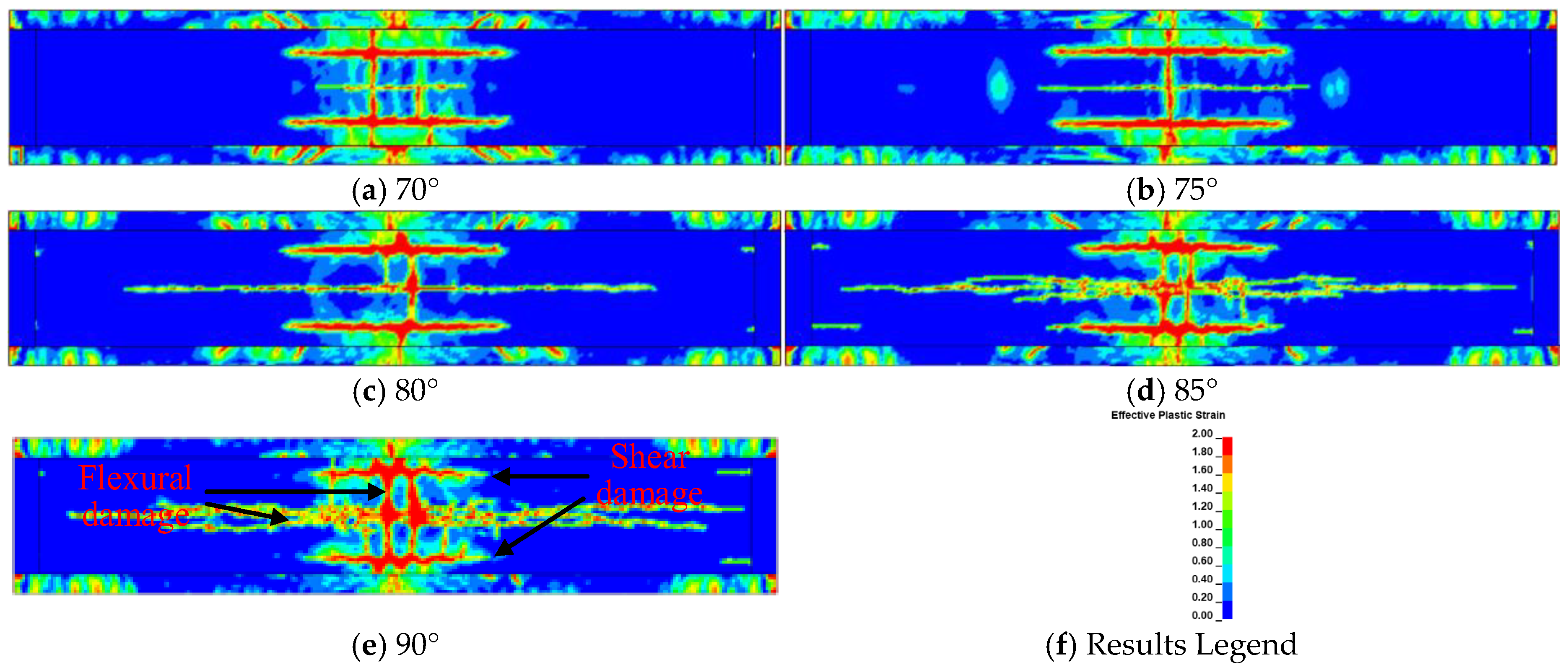
Figure 17 and Figure 18 show the damage modes of bridge upper decks and bottom decks with different dip angles at t = 11 s. As shown, the bridge upper deck corresponding to a dip angle of β = 70° is more severely damaged than those upper decks corresponding to other dip angles, and the damage degree of the bridge upper deck decreases with the increase in dip angle. However, with the increase in dip angle, the flexural damage and shear damage of the bridge bottom deck is more severe. This is because the cross-sectional stiffness and the shear capacity of the box girder bridge with CSWs increases with the increase in dip angle.
Figure 19 shows the midspan deflection time histories of bridges with different dip angles. As shown, the midspan deflection of the bridge bottom deck with a dip angle of β = 70° changes intensity non-periodically. This is because the dip angle of the CSW is too low, resulting in an ineffective vertical deformation constraint between the upper and bottom decks. The dynamic response caused by blast loading mainly occurs on the bridge upper deck, as shown in Figure 17 and Figure 18. As the dip angle of the CSW increases, the midspan deflection of the bridge bottom deck exhibits periodic vibration. By comparing the residual deflection at the midspan of the bridge, the optimal dip angle of the CSW for a box girder bridge is 85°. The bridge bottom deck with a dip angle of 90° experiences more severe shear damage compared to other dip angles, and for the CSW with a low dip angle, it is difficult to effectively transmit the deformation of the upper deck.

5. Discussion

The numerical investigation conducted in this study highlights the significant influence of key geometric parameters of corrugated steel webs (CSWs)—namely the folding angle, height–span ratio, and dip angle—on the blast resistance of box girder bridges. The findings provide valuable insights into the optimal design of CSWs under blast loading, yet also reveal several aspects that warrant further exploration.
The folding angle of CSWs markedly affects both the local stiffness and the stress distribution within the bridge deck. While larger folding angles enhance the shear capacity and local stiffness of the webs, they also intensify stress concentrations at the web–deck junctions, leading to more severe damage in the deck. The optimal folding angle of 55° identified in this study suggests a balance between structural stiffness and damage mitigation, emphasizing the need for a compromise between global stiffness and local stress reduction. The height–span ratio directly influences the global bending and shear stiffness of the bridge. Although increasing the cross-sectional height reduces the midspan deflection and damage in the bottom deck, it also diminishes the shear stiffness of the section. The identified optimal height of 3.0 m represents a trade-off between deformation control and energy absorption capacity. This implies that simply increasing the cross-sectional height may not always be beneficial for blast resistance, and a holistic view of energy dissipation mechanisms is necessary.
The dip angle of CSWs plays a critical role in governing the vertical deformation compatibility between the upper and bottom decks. Higher dip angles improve the overall sectional stiffness and shear resistance but exacerbate damage in the bottom deck due to more efficient transmission of blast-induced forces. Despite these insights, several limitations and future research directions should be addressed. First, the study primarily relies on numerical simulations validated against limited experimental data. Future work should include physical blast tests to verify the numerical models and capture more complex failure mechanisms. Second, the interaction between multiple parameters (e.g., combined effects of folding angle and dip angle) is not systematically studied; a parametric optimization study using methods such as response surface methodology or machine learning could provide more comprehensive design guidelines. Third, material nonlinearity, strain rate effects, and potential failure modes at connections are simplified in the models—more refined material models and detailed joint analyses are recommended. In conclusion, while this study offers practical guidance for the blast-resistance design of CSW bridges, it also underscores the need for multidisciplinary approaches integrating advanced modeling, experimental validation, and optimization techniques to enhance the safety and durability of such structures under extreme loads.
Furthermore, this paper assumes that corrugated steel webs do not carry axial force. The influence of axial force on the blast-resistance performance of building structures with CSWs has been studied by some scholars [39,40,41]. It is found that the presence of axial compression force in CSWs of building structures may reduce the buckling resistance of structures, increasing their susceptibility to instability and failure under blast loading. However, the influence of axial force on box girders with CSWs under explosion loading has not been studied. The numerical models in this paper do not consider the effect of material aging, corrosion of CSWs, and temperature variations on the blast resistance of box girders with CSWs. These issues can be addressed in future investigations.

6. Conclusions

In this study, the dynamic response of box girder bridges with CSWs subjected to blast load is studied. The optimal design of CSWs for box girder bridges subjected to blast loads is investigated. The numerical model of bridges with CSWs is established through the software LS-DYNA. The results are given below.
  • The bridge deck around the CSWs in the middle span of the bridge are severely damaged because of the stress concentration at the intersection of the CSWs and the bridge deck, and the bridge deck is more severely damaged with the increase in folding angle of the CSW. The local stiffness and the shear capacity of the CSW increases with the increase in folding angle. The box girder bridge with a folding angle of 55° has better blast-resistance capacity than bridges composed of other folding angles because the blast-resistance performance of box girder bridges with CSWs is related to the local stiffness of the CSW and the stress concentration at the bridge deck induced by the folding effect of the CSW.
  • As the height–span ratio increases, the bending stiffness of the CSW decreases, and the flexural damage around the centerline of the upper deck gradually expands toward to the interface of bridge deck and CSW. The damage area of the bottom deck around the interface of CSW and bridge deck decreases with the increase in CSW height. The shear stiffness of the bridge cross-section decreases as the height–span ratio of the bridge increases. The bottom deck of the bridge is less severely damaged with the increase in height–span ratio. Considering the residual deflection of the bridge bottom deck and the energy absorption capacity of the CSW, the optimal cross-sectional height of the bridge is 3 m.
  • The damage degree of the bridge upper deck decreases with the increase in CSW dip angle. The cross-sectional stiffness, the shear capacity, and vertical deformation constraint of the bridge with CSWs increases with the increase in dip angle. Therefore, the flexural damage and shear damage of the bridge bottom deck is more severe with the increase in CSW dip angle. The optimal dip angle of the CSWs for box girder bridges is 85° by comparing the residual deflection at the middle span of the bridge.

Author Contributions

Conceptualization, C.X. and H.J.; methodology, C.X. and H.J.; software, C.X., H.J. and Y.X.; validation, Y.X., X.H. and J.Z.; formal analysis, Y.X.; writing—original draft preparation, C.X., H.J. and Y.X.; writing—review and editing, C.X., X.H. and J.Z. All authors have read and agreed to the published version of the manuscript.

Funding

This study is supported by the China Construction Sixth Engineering Bureau Co., Ltd. via CSCEC-2022-Z-25.

Data Availability Statement

The data presented in this study are available from the corresponding author upon reasonable request.

Acknowledgments

The authors would like to thank China Construction Sixth Engineering Bureau Co., Ltd. for their support.

Conflicts of Interest

All Authors were employed by the company China Construction Sixth Engineering Bureau Co., Ltd. The funder was not involved in the study design, collection, analysis, interpretation of data, the writing of this article or the decision to submit it for publication.

References

  1. Katsimpini, P.S.; Papagiannopoulos, G.; Hatzigeorgiou, G. Nonlinear Analysis of Bridges Considering Soil–Structure Interaction and Travelling Wave Effects Under Combined Train and Near-Fault Seismic Loads. Appl. Sci. 2024, 14, 11688. [Google Scholar] [CrossRef]
  2. Fathy, E.; Eraky, A.; Mustafa, S.A.; Al-Sallami, A.A. Controlling seismic torsional behavior of skewed bridges to reduce the risk of unseating damage. Structures. Structures 2025, 80, 109874. [Google Scholar] [CrossRef]
  3. Xu, Y.; Xu, Z.D.; Hu, H.; Guo, Y.Q.; Huang, X.H.; Zhang, Z.W.; Zhang, T.; Xu, C. Experiment, Simulation, and Theoretical Investigation of a New Type of Interlayer Connections Enhanced Viscoelastic Damper. Int. J. Struct. Stab. Dyn. 2025, 25, 2550045. [Google Scholar] [CrossRef]
  4. Jiang, R.J.; Au, F.T.K.; Xiao, Y.F. Prestressed Concrete Girder Bridges with Corrugated Steel Webs: Review. J. Struct. Eng. 2015, 141, 04014108. [Google Scholar] [CrossRef]
  5. He, J.; Liu, Y.; Chen, A.; Yoda, T. Mechanical behavior and analysis of composite bridges with corrugated steel webs: State-of-the-art. Int. J. Steel Struct. 2012, 12, 321–338. [Google Scholar] [CrossRef]
  6. Easley, J.T. Buckling Formulas for Corrugated Metal Shear Diaphragms. J. Struct. Div. 1975, 101, 1403–1417. [Google Scholar] [CrossRef]
  7. Johnson, R.P.; Cafolla, J.; Bernard, C. Corrugated webs in plate girders for bridges. Struct. Build. 1997, 122, 157–164. [Google Scholar] [CrossRef]
  8. Driver, R.G.; Abbas, H.H.; Sause, R. Shear Behavior of Corrugated Web Bridge Girders. J. Struct. Eng. 2006, 132, 195–203. [Google Scholar] [CrossRef]
  9. Hassanein, M.F.; Kharoob, O.F. Shear buckling behavior of tapered bridge girders with steel corrugated webs. Eng. Struct. 2014, 74, 157–169. [Google Scholar] [CrossRef]
  10. Bergmann, L.; Reissner, E. On the Bending and Torsion of Rectangular Plates with Unequal Bending Stiffness in Two Perpendicular Directions. J. Appl. Mech. 1928, 5, 123–145. [Google Scholar]
  11. Elgaaly, M.; Seshadri, A.; Rodriquez, R.; Ibrahim, S. Bridge Girders with Corrugated Webs. Transp. Res. Rec. J. Transp. Res. Board 2000, 1696, 162–170. [Google Scholar] [CrossRef]
  12. Elgaaly, M.; Seshadri, A. Girders with Corrugated Webs under Partial Compressive Edge Loading. J. Struct. Eng. 1997, 123, 783–791. [Google Scholar] [CrossRef]
  13. Elgaaly, M.; Hamilton, R.W.; Seshadri, A. Shear Strength of Beams with Corrugated Webs. J. Struct. Eng. 1996, 122, 390–398. [Google Scholar] [CrossRef]
  14. Luo, R.; Edlund, B. Shear capacity of plate girders with trapezoidally corrugated webs. Thin-Walled Struct. 1996, 26, 19–44. [Google Scholar] [CrossRef]
  15. Luo, R.; Edlund, B. Ultimate strength of girders with trapezoidally corrugated webs under patch loading. Thin-Walled Struct. 1996, 24, 135–156. [Google Scholar] [CrossRef]
  16. El Metwally, A.; Loov, R.E. Corrugated steel webs for prestressed concrete girders. Mater. Struct. 2003, 36, 127–134. [Google Scholar] [CrossRef]
  17. Jin, H.; Hao, H.; Hao, Y.; Chen, W. Predicting the response of locally resonant concrete structure under blast load. Constr. Build. Mater. 2020, 252, 118920. [Google Scholar] [CrossRef]
  18. Jin, H.; Hao, H.; Xu, C.; Huang, Z.; Chen, W. Dynamic response of metaconcrete beam under blast load. Int. J. Struct. Stab. Dyn. 2023, 23, 2350178. [Google Scholar] [CrossRef]
  19. Jin, H.; Hao, H.; Chen, W.; Xu, C. Effect of enhanced coating layer on the bandgap characteristics and response of metaconcrete. Mech. Adv. Mater. Struct. 2021, 30, 175–188. [Google Scholar] [CrossRef]
  20. Yang, S.; Liu, Z.; Wang, S.; Zhong, W.; Zhang, R.; Yao, X. Dynamic response and failure analysis for urban bridges under far-field blast loads. Eng. Struct. 2023, 285, 116043. [Google Scholar] [CrossRef]
  21. Tetougueni, C.D.; Zampieri, P. Structural response of cable-stayed bridge subjected to blast load. Procedia Struct. Integr. 2019, 18, 765–774. [Google Scholar] [CrossRef]
  22. Pan, Y.; Ventura, C.E.; Cheung, M.M.S. Performance of highway bridges subjected to blast loads. Eng. Struct. 2017, 151, 788–801. [Google Scholar] [CrossRef]
  23. Vaghefi, M.; Mobaraki, B. Evaluation of the effect of explosion on the concrete bridge deck using LS-DYNA. Int. Rev. Civ. Eng. 2021, 12, 135. [Google Scholar] [CrossRef]
  24. Gholipour, G.; Billah, A.H.M.M.; Mousavi, A.A. Finite element-based reliability analysis of RC bridge piers subjected to the combination of barge impact and blast loads. Ocean Eng. 2022, 264, 112543. [Google Scholar] [CrossRef]
  25. Lv, C.; Yan, Q.; Li, L.; Li, S. Field test and probabilistic vulnerability assessment of a reinforced concrete bridge pier subjected to blast loads. Eng. Fail. Anal. 2023, 143, 106802. [Google Scholar] [CrossRef]
  26. Hashemi, S.K.; Bradford, M.A.; Valipour, H.R. Dynamic response of cable-stayed bridge under blast load. Eng. Struct. 2016, 127, 719–736. [Google Scholar] [CrossRef]
  27. Yu, S.; Wu, H.; Zhang, G.; Wang, Z.; Yao, J.; Li, H.; Liu, C. Experimental study on anti-shallow-buried-explosion capacity of a corrugated steel-plain concrete composite structure. Int. J. Impact Eng. 2023, 172, 104393. [Google Scholar] [CrossRef]
  28. Cao, K.; Fu, Q.; Zhang, J.; Tang, C.; Huang, J.; Wang, C.; Bai, W. Effect of corrugated steel angle on the damage characteristics and anti-explosion performance of corrugated steel–concrete composite structures. Struct. Des. Tall Spéc. Build. 2024, 33, e2112. [Google Scholar] [CrossRef]
  29. Mo, Y.L.; Jeng, C.H.; Chang, Y.S. Torsional behavior of prestressed concrete box-girder bridges with corrugated steel webs. Struct. J. 2000, 97, 849–859. [Google Scholar]
  30. Abbas, H.H.; Sause, R.; Driver, R.G. Shear Strength and Stability of High Performance Steel Corrugated Web Girders. In Proceedings of the Structural Stability Research Council 2002 Annual Stability Conference, Seattle, DC, USA, 24–27 April 2002. [Google Scholar]
  31. Zha, S.; Liu, D.; Zhang, J.; Deng, W.; Gu, J. Calculation method for flexural capacity of composite girders with corrugated steel webs. J. Constr. Steel Res. 2024, 214, 108476. [Google Scholar] [CrossRef]
  32. Cantor, B. Hooke’s Law //The Equations of Materials; Oxford University Press: Oxford, UK, 2020; pp. 207–225. [Google Scholar]
  33. JTG/T 2231-01—2020; Specifications for Seismic Design of Highway Bridges. China Communications Press: Beijing, China, 2020.
  34. T/CECS 736-202; Standard for Blast Protection Design of Civil Buildings. China Architecture & Building Press: Beijing, China, 2020.
  35. Malvar, L.J.; Ross, C.A. Review of strain rate effects for concrete in tension. ACl Mater. J. 1999, 96, 614–616. [Google Scholar]
  36. CEB; CEBFIP. Model Code 1990; Redwood Books: Wiltshire, UK, 1993. [Google Scholar]
  37. Malvar, L. Review of Static and Dynamic Properties of Steel Reinforcing Bars. ACI Mater. J. 1998, 95, 609–616. [Google Scholar] [CrossRef]
  38. Huang, Z.; Chen, W.; Hao, H.; Chen, Z.; Pham, T.M.; Tran, T.T.; Elchalakani, M. Shear behaviour of ambient cured geopolymer concrete beams reinforced with BFRP bars under static and impact loads. Eng. Struct. 2021, 231, 111730. [Google Scholar] [CrossRef]
  39. Tong, J.-Z.; Yu, C.-Q.; Tong, G.-S.; Xu, S.-L. Experimental study on axial resistant behavior of multi-celled corrugated-plate CFST walls. Eng. Struct. 2023, 295, 116795. [Google Scholar] [CrossRef]
  40. Yu, C.-Q.; Tong, J.-Z.; Tong, G.-S.; Xu, S.-L.; Chen, M. Axial compressive performance and design of multi-celled corrugated-plate CFST walls. Structures 2023, 57, 105303. [Google Scholar] [CrossRef]
  41. Lv, L.-J.; Peng, X.-T.; Yang, T.-C. Study on lateral-force resistance performance of cross-slanted corrugated steel plate shear wall. J. Phys. Conf. Ser. 2019, 1168, 022070. [Google Scholar]
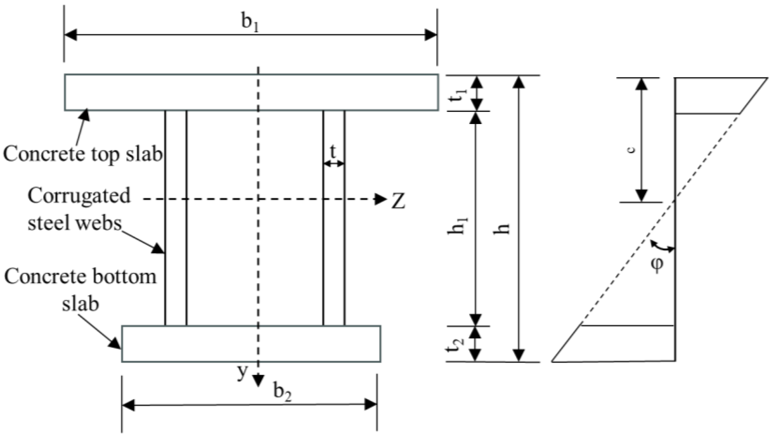
Figure 1. Cross-section and normal strain distribution mode of a box girder with CSWs.
Infrastructures 10 00256 g001
Figure 2. Shearing stress calculation diagram.
Infrastructures 10 00256 g002
Figure 3. Numerical model of box girder bridge with CSWs.
Infrastructures 10 00256 g003
Figure 4. Schematic diagram of box girder bridge with CSWs.
Infrastructures 10 00256 g004
Figure 5. Displacement time histories at E1 of bridges with different mesh sizes.
Infrastructures 10 00256 g005
Figure 6. Numerical model of concrete beam subjected to drop-weight impact.
Infrastructures 10 00256 g006
Figure 7. Comparison of midspan deflection.
Infrastructures 10 00256 g007
Figure 8. Comparison of damage modes: (a) experimental result, (b) numerical result.
Infrastructures 10 00256 g008
Figure 9. Damage modes of box girder bridges composed of various CSWs with different folding angles at t = 11 s.
Infrastructures 10 00256 g009
Figure 10. Damage modes of the bottom deck of box girder bridges at t = 11 s.
Infrastructures 10 00256 g010
Figure 11. Damage modes of CSWs with different folding angles.
Infrastructures 10 00256 g011
Figure 12. Midspan deflection time histories of box girder bridges with different folding angles.
Infrastructures 10 00256 g012
Figure 13. Damage modes of bridge upper decks with different height–span ratios at t = 11 s.
Infrastructures 10 00256 g013aInfrastructures 10 00256 g013b
Figure 14. Damage modes of bottom decks with different height–span ratios at t = 11 s.
Infrastructures 10 00256 g014
Figure 15. Midspan deflection time histories of bridges with different height–span ratios.
Infrastructures 10 00256 g015
Figure 16. Energy time histories of bridges with different height–span ratios.
Infrastructures 10 00256 g016
Figure 17. Damage modes of bridge upper decks with different dip angles at t = 11 s.
Infrastructures 10 00256 g017aInfrastructures 10 00256 g017b
Figure 18. Damage modes of bottom decks with different dip angles at t = 11 s.
Infrastructures 10 00256 g018
Figure 19. Midspan deflection time histories of bridges with different dip angles.
Infrastructures 10 00256 g019
Table 1. Keywords used to define the numerical model.
ComponentKeyword
Concrete deck, cushion plate, end plate* MAT_072R3
Reinforcement, CSW* Mat_Piecewise_Linear_Plasticity (Mat_024)
Erosion criterion of concrete* Mat_Add_Erosion
(Maximum principal strain: 0.1)
Contact conditionKeyword
Concrete deck and reinforcement
Concrete deck and CSW
* Constrained_Lagrange_in_Solid
Concrete deck, end plate, cushion plate* Automatic_ Surface_to_Surface
Table 2. Material parameters of different components.
MaterialParameterValue
Concrete (concrete deck, cushion plate, end plate)Compressive strength (MPa)34
Density (kg/m3)2300
Poisson’s ratio0.19
ReinforcementElastic modulus (GPa)200
Density (kg/m3)7800
Yield stress (MPa)300
Table 3. Comparison of experimental and numerical results.
DisplacementExperimental ResultNumerical ResultError
Peak displacement (mm)30.129.2−3%
Residual displacement(mm)9.64.9−49%
Disclaimer/Publisher’s Note: The statements, opinions and data contained in all publications are solely those of the individual author(s) and contributor(s) and not of MDPI and/or the editor(s). MDPI and/or the editor(s) disclaim responsibility for any injury to people or property resulting from any ideas, methods, instructions or products referred to in the content.