1. Introduction
The integrity assessment of underwater infrastructure is a critical component of broader structural health monitoring (SHM) frameworks. While traditional SHM for bridges and dams has often relied on networks of physical sensors (e.g., accelerometers or strain gauges) to monitor global response parameters, visual inspection remains the primary method for identifying localized damage such as cracking. The automation of this visual inspection, particularly in challenging underwater environments, is therefore a vital pursuit to complement existing SHM methodologies and create more holistic, data-driven integrity management systems. Underwater infrastructures such as bridge piers, offshore platforms, and subsea pipelines play a vital role in transportation and energy systems [
1]. Among the various types of structural damage that can occur in these environments, cracks are considered one of the most critical indicators of early-stage degradation [
2,
3]. The timely detection of cracks is paramount not only for assessing structural integrity, but also for ensuring functional performance. For hydraulic structures like dams and reservoirs, cracks directly compromise durability and impermeability, leading to seepage, internal erosion, and other detrimental processes that can accelerate deterioration. This underscores the practical engineering significance of developing robust, high-precision crack detection systems. If left undetected, they may propagate over time and lead to structural failure, posing risks to public safety and causing substantial economic losses [
4]. Therefore, the timely and accurate detection of underwater cracks is essential for ensuring the integrity and reliability of these submerged structures [
5].
Traditional methods for underwater crack detection largely rely on manual inspections, remotely operated vehicles (ROVs) [
6,
7], or sonar-based imaging systems [
8]. While sonar and laser scanning are effective in highly turbid conditions, they often lack the resolution necessary to detect fine-grained surface cracks [
9,
10]. In contrast, optical imaging offers high-resolution and texture-rich visual information that is more intuitive for identifying small-scale surface defects. However, underwater optical images suffer from a variety of degradations, including color distortion, low contrast, scattering, and non-uniform illumination caused by the inherent physics of light propagation in water [
11]. Beyond vision-based techniques, the broader field of structural health monitoring (SHM) has developed advanced methodologies for damage assessment in marine and offshore environments. Particularly relevant are vibration-based strategies that analyze the dynamic responses of structures to environmental loads, such as wind and wave forces [
12]. These challenges make the task of underwater crack detection particularly difficult using conventional image processing or even standard deep learning models.
Recent advancements in deep learning, especially convolutional neural networks (CNNs) [
13] and Transformer-based architectures [
14,
15], have shown great promise in automated crack detection for road pavements [
16,
17,
18], concrete surfaces [
19], and other civil infrastructures [
20,
21]. However, these models are primarily trained and validated on land-based datasets with clear visibility and well-structured textures. When applied directly to underwater scenes, their performance degrades significantly due to domain shifts and the lack of robustness to underwater-specific noise and degradation.
In recent years, research on image-based underwater structure damage recognition using deep learning has mainly focused on three technical directions: image classification, object detection, and semantic segmentation. It is important to note that this excludes a parallel body of work on non-image-based damage detection (e.g., using accelerometers, strain gauges, or acoustic emission sensors), which utilizes deep learning for time-series signal analysis rather than visual recognition. In the field of image classification (determining the existence of damage through global image analysis), Zhu et al. [
22] proposes an improved VanillaNet architecture, which effectively alleviates the long-tail distribution problem of underwater dam crack data by introducing the Seesaw loss function. In comparison with advanced models such as ConvNeXtV2 and RepVGG, the classification accuracy is improved by 2.66% compared to the original network. For object detection technology (precise defect localization using bounding boxes), Li et al. [
23] optimized the YOLOv4 framework by using lightweight MobileNetV3 instead of CSPDarknet as the feature extraction backbone network. By reconstructing the feature layer scale parameters and inputting the primary features into an improved feature fusion module, the deep integration of multi-level features was achieved.
Compared to the qualitative judgment of classification and the box selection localization of detection, semantic segmentation can provide more refined damage representation through its pixel-level recognition ability [
24,
25]. This technology achieves image semantic analysis through pixel-by-pixel classification, demonstrating significant advantages in the field of industrial inspection, especially in the analysis of crack morphology characteristics and the quantitative evaluation of the degree of damage, which has important engineering value. Typical cases include the following: Hou et al. [
26] constructed an underwater bridge pier defect recognition system based on U
2-Net, and achieved the highest intersection to union ratio index of 0.73 by optimizing the edge detection module, which can still accurately extract contour details in complex underwater environments; Sun et al. [
27] proposed a two-stage detection scheme, which first uses YOLOv7 to locate the defect areas of underwater concrete structures, and then uses an improved DeepLabV3+ network to complete pixel-level segmentation. For typical defects such as exposed steel bars and concrete spalling, the average intersection to union ratio reaches 0.914.
In response to the practical challenge of the difficulty in obtaining underwater defect data, the academic community has explored innovative paths to break through data bottlenecks. On the one hand, some researchers [
28,
29] have verified the effectiveness of transfer learning strategies in a few sample scenarios, such as the lightweight LinkNet framework constructed in reference [
30], which achieves real-time crack segmentation and quantitative analysis in complex underwater environments through hybrid transfer learning. On the other hand, cutting-edge research attempts to integrate prior knowledge of physics. Teng et al. [
31] pioneered the “knowledge-guided detection” paradigm, which extracts morphological features by calculating the fractal dimension matrix of cracks and uses it as a prompt input for the Segment Anything model (SAM) to construct a plug and play defect segmentation system. Ultimately, excellent performance indicators with an average accuracy of 97.6%, intersection to union ratio of 0.89, and F1 value of 0.95 were obtained.
However, most existing approaches treat the segmentation task purely as a data-driven problem [
32], overlooking physical domain knowledge such as underwater light attenuation, the surface geometry of structures, and the inherent uncertainty in predictions. As a result, they often exhibit poor generalization when confronted with complex underwater environments, leading to false positives, missed detections, and overconfident predictions in ambiguous regions. While recent efforts in 2024–2025 have begun to incorporate physical models [
5] or leverage foundational models like the SAM [
31] for crack segmentation, they often treat these elements in isolation. Similarly, transfer learning strategies [
33] address data scarcity, but do not explicitly model the inherent uncertainty in underwater predictions.
Beyond architectural advancements, quantifying the prediction uncertainty has emerged as a critical direction for improving the reliability of deep learning models in real-world applications, especially when dealing with domain shifts. Recent studies have increasingly incorporated uncertainty estimation into segmentation frameworks to identify ambiguous regions and enhance cross-domain robustness. For instance, Kwon et al. [
34] proposed a Bayesian U-Net for medical image segmentation, using Monte Carlo Dropout to model epistemic uncertainty and improve generalization across different scanner domains. Similarly, Zhou et al. [
35] developed an uncertainty-aware domain adaptation framework for semantic segmentation in autonomous driving, where entropy minimization on the target domain data helps to reduce prediction variance. These approaches demonstrate that explicitly modeling uncertainty is a powerful paradigm for addressing distribution shifts. However, their application in underwater structural inspection remains largely unexplored. Our work fills this gap by integrating an uncertainty-aware Transformer module specifically designed for the challenges of underwater optical imagery, such as scattering and low contrast, providing not only accurate segmentation, but also a crucial confidence measure for operational decision-making.
Unlike these approaches, this work is the first to concurrently integrate a physics-guided enhancement network, a geometry-aware dual-branch segmentation head, and an uncertainty-quantifying Transformer within a unified framework. This co-design allows each component to complement the others: the physical model corrects degradation at the input level, the geometric branch provides mid-level structural priors, and the uncertainty module offers output-level reliability estimation. This holistic strategy fundamentally differs from and advances upon incremental combinations of existing techniques, providing a more robust and interpretable solution for the underwater domain.
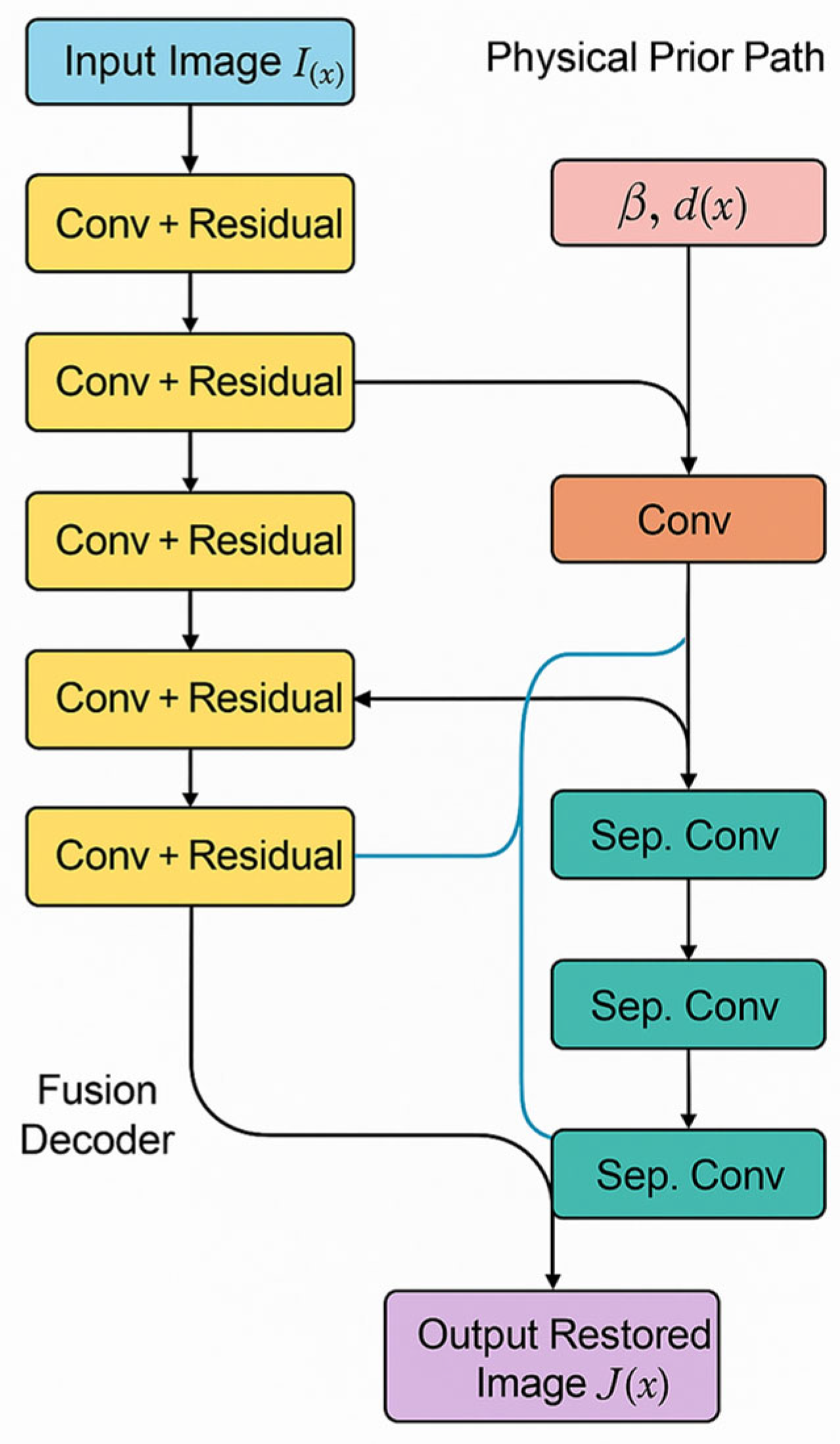
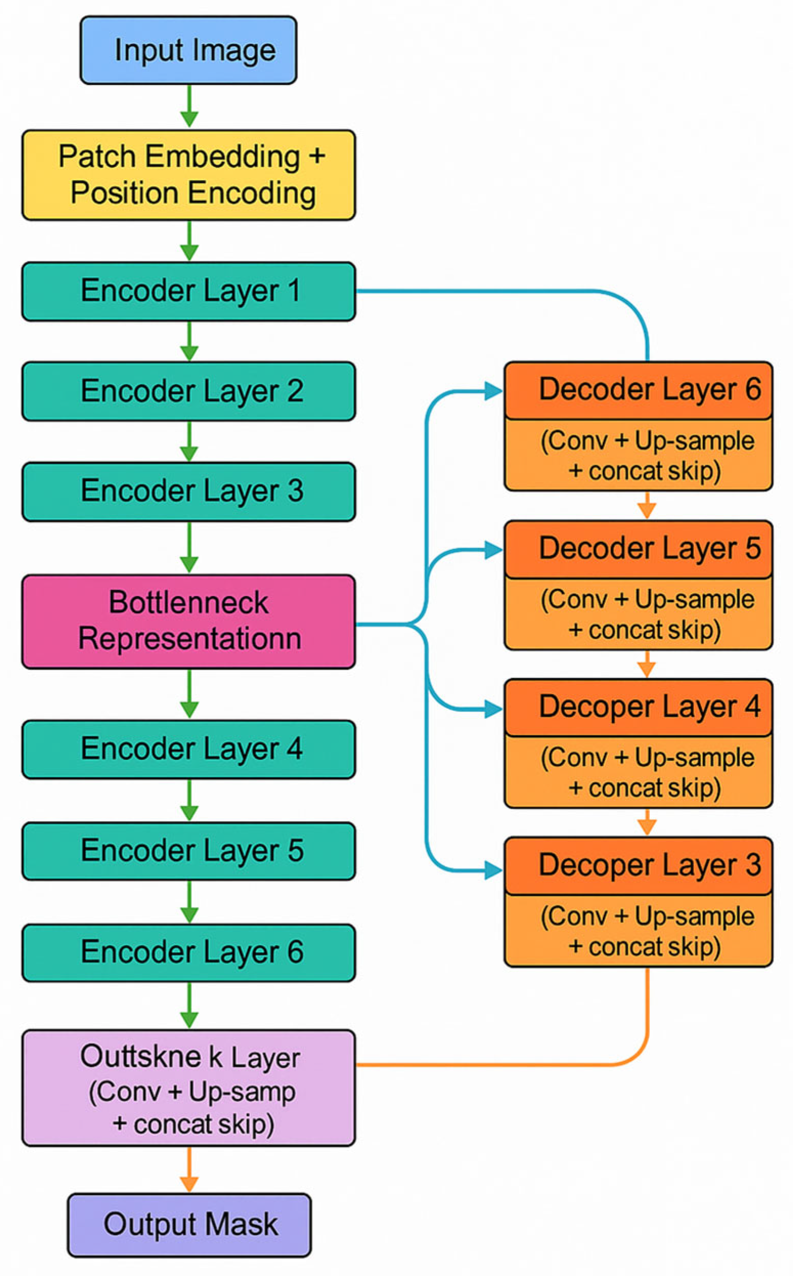
To overcome these limitations, this paper proposes a novel deep learning framework that integrates physical priors and uncertainty modeling for accurate crack detection in underwater optical images. Unlike existing methods, our approach introduces a physics-guided enhancement module that explicitly incorporates underwater light attenuation characteristics to improve visual quality before segmentation. This paper also proposes a dual-branch segmentation architecture that not only captures semantic information, but also learns curvature-based geometric features to better align with the physical properties of crack shapes. Furthermore, an uncertainty-aware Transformer module is integrated to estimate both epistemic and aleatoric uncertainties, allowing the model to identify ambiguous regions and suppress overconfident predictions. The major contributions of this study can be summarized as follows:
- (1)
A physics-guided enhancement network that explicitly integrates the underwater light propagation model to invert the image formation process, directly addressing color distortion and scattering artifacts at the source, rather than applying generic image enhancement;
- (2)
A geometric-aware dual-branch segmentation architecture that uniquely fuses high-level semantic features with low-level curvature maps, encoding the geometric property that cracks manifest as high-curvature surface irregularities. This provides a stronger inductive bias for precise boundary delineation than standard architectures;
- (3)
An uncertainty-aware Transformer module that leverages Monte Carlo Dropout not only for Bayesian uncertainty estimation, but also to actively guide the model’s attention during training and inference toward ambiguous, low-confidence regions (e.g., faint cracks or strong reflections), significantly reducing the number of overconfident errors;
- (4)
Benchmarking and evaluation: this paper constructs a dataset of annotated underwater crack images, and extensive experiments are conducted comparing our method with several State-of-the-Art segmentation models.
This work offers a comprehensive solution to the underwater crack detection problem by fusing physical understanding with modern deep learning strategies. Experimental results demonstrate that our proposed method significantly outperforms the existing approaches in terms of segmentation accuracy, uncertainty quantification, and generalization ability, thus paving the way for safer and more efficient underwater infrastructure inspection.
3. Experiments and Results
This section focuses on the underwater crack detection framework based on physical perception enhancement and the uncertainty perception Transformer proposed in this article. Systematic comparative experiments, ablation experiments, and quantitative and qualitative evaluations are conducted to verify the detection performance, generalization ability, and adaptability to changes in lighting and the water quality of the model.
3.1. Experimental Setup
3.1.1. Dataset Preparation
This paper uses a self-collected dataset comprising 1037 high-resolution images of underwater bridge cracks. While the absolute number of images may appear modest, the dataset’s strength lies in its diverse representation of real-world inspection conditions, which is crucial for evaluating model robustness. The images were collected from multiple infrastructure sites across different geographical locations, ensuring a variety of crack morphologies (e.g., linear, map-like, and fine hairline cracks) and structural backgrounds. The data captures a wide range of challenging environmental conditions:
Water Quality: Ranging from clear visibility (attenuation coefficient β ≈ 0.1 m−1) to highly turbid water (β ≈ 2.5 m−1) with suspended sediments and organic matter.
Lighting Conditions: Including uniform artificial lighting, non-uniform natural light, strong specular reflections, and low-light scenarios (image intensity values ranging from 10 to 250 on a 0–255 scale).
Water Depth: Spanning from shallow water (<2 m) to deeper sections (>10 m), affecting color distortion and light attenuation.
Viewing Angles and Scales: Images were captured at various distances (0.5–3 m) and angles from the structure surface to simulate different inspection paths.
This deliberate variability ensures that the dataset is representative of the operational challenges faced in practical underwater inspections. The dataset was split into a training set (829 images) and a test set (208 images) at an 8:2 ratio, ensuring no data leakage between sets. Due to the limited dataset size, a separate validation set was not partitioned to avoid compromising the statistical power of the training and test sets. All images were resized to 512 × 512 pixels. Extensive data augmentation techniques were applied to the training set to further improve generalization, including random rotation (±45°), horizontal/vertical flipping, color jitter (brightness, contrast, and saturation adjustments of up to ±20%), and additive Gaussian noise (σ = 0.01–0.05).
The pixel-level annotation of crack regions was performed by a team of three qualified structural engineers with extensive experience in underwater inspection.
3.1.2. Implementation Details
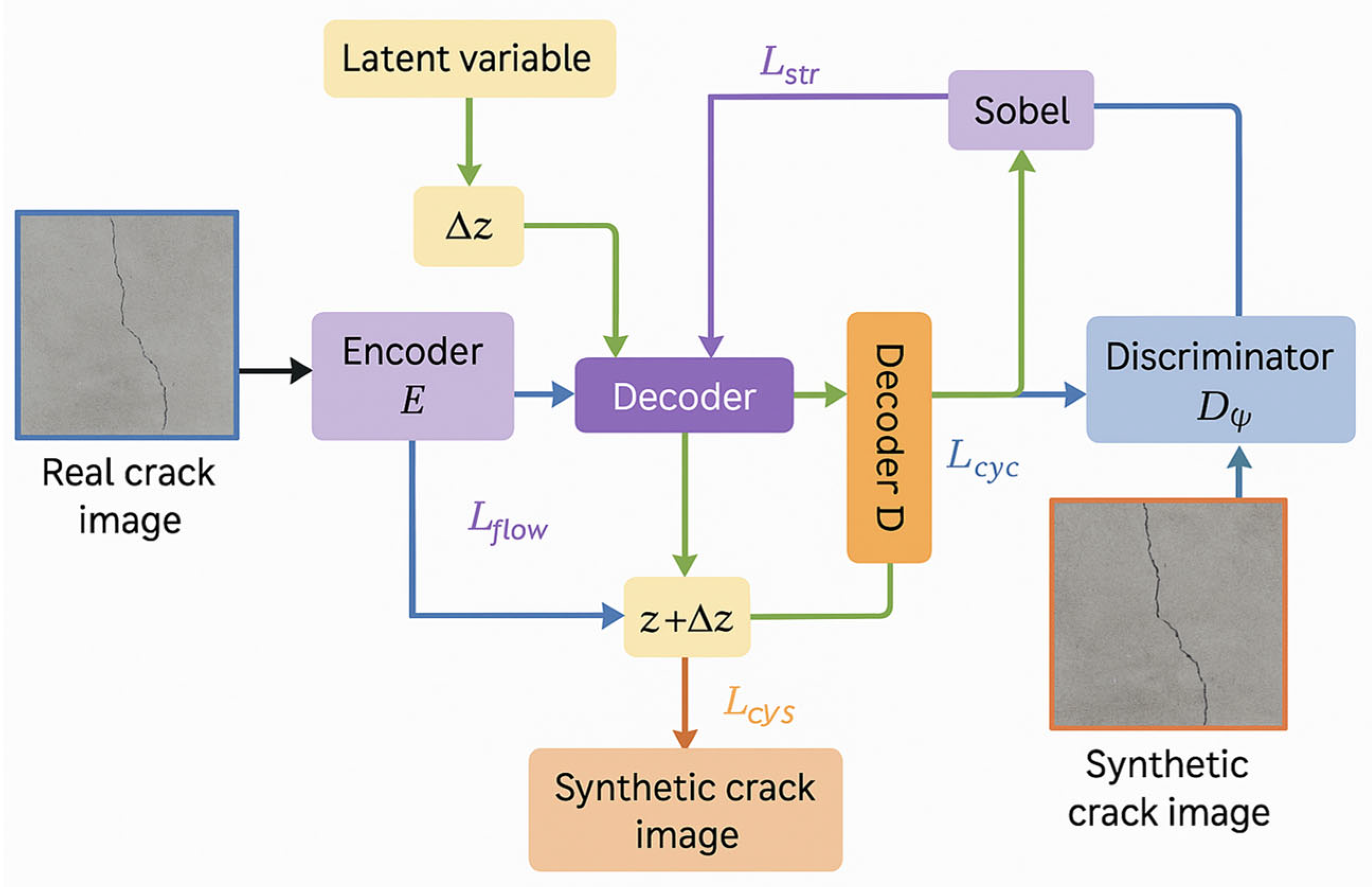
The experiment is implemented based on the PyTorch 2.0 deep learning framework, and the hardware platform uses two NVIDIA RTX 4090 GPUs for parallel accelerated computing. During the model training process, the optimizer uses Adam, the initial learning rate is set to 1 × 10⁻⁴, and the cosine annealing strategy is used to dynamically adjust the learning rate. All experiments were conducted using a batch size of 16 and a training epoch of 50, and optimized for video memory usage and computational efficiency through mixed precision training. The following hyperparameters were used for training each component: Optimizer: All models were trained using the AdamW optimizer, with an initial learning rate set to 1 × 10⁻⁴ and momentum parameters of β1 = 0.9 and β2 = 0.999. Weight decay (0.01) and cosine annealing learning rate scheduling strategies were applied. The training batch size was uniformly set to 16. The weight coefficients of the loss function were empirically determined as follows: reconstruction loss lambda = 1.0, perceptual loss = 0.1, and edge loss lambda ∝ = 0.05. The loss weights in generative adversarial training were set as follows: α = 1.0 (flow loss), β = 0.5 (adversarial loss), γ = 0.2 (cyclic consistency loss), and δ = 0.1 (structural loss).
3.2. Evaluation Metrics
To comprehensively evaluate the crack segmentation performance of the model, this article adopts the following four core indicators, covering pixel-level classification accuracy, regional consistency, small target sensitivity, and model uncertainty quantification ability. The definitions and calculation formulas for each indicator are as follows:
- (1)
The Pixel Accuracy (PA) measures the proportion of correctly classified pixels among all pixels, calculated using the following formula:
Among these, is the number of true positive pixels for type (cracks/background), is the number of false positive pixels, and is the number of false negative pixels;
- (2)
The mean Intersection over Union (mIoU) is used to calculate the mean Intersection over Union (IoU) between the crack and the background area, reflecting the accuracy of overlapping regions:
Among these, is the number of categories ( = 2 in this paper) and the denominator is the union of the predicted and real regions;
- (3)
The Dice Similarity Coefficient is more sensitive to small targets with non-uniform distribution, such as fine cracks. The calculation formula is as follows:
Among these, the closer Dice is to 1, the higher the overlap between the predicted area and the true label;
- (4)
The Uncertainty Entropy Map, using Monte Carlo Dropout T sampling times (T = 10 in this paper), calculates the pixel-level prediction variance and maps it to the entropy values to quantify model uncertainty:
Among these, K = 2 (crack/background) and is the predicted probability of the k-th class. The lower the entropy value, the higher the confidence of the model in pixel classification.
The use of the peak signal-to-noise ratio (PSNR) for evaluating underwater image restoration presents a well-known challenge due to the general absence of a true ground truth reference image (J(x)) for in situ data. To address this, our PSNR calculations were performed under two distinct scenarios:
Synthetic Data with Paired Ground Truth: For a subset of images, we employed the physical forward model (Equation (1)) to generate synthetic underwater degradations from clear, ground truth images (J(x)) captured in air. For these synthetically degraded images, the original clear image serves as the perfect reference, enabling a valid and objective PSNR calculation.
Real-World Data with Expert-Selected Reference: For real underwater images where a perfect reference is unattainable, we utilized the expert-selected ‘best-quality’ image from a sequence (as described in
Section 2.1.3) as the reference
. While this does not represent an absolute ground truth, it provides a reasonable benchmark for comparing the relative improvement in perceptual quality and structural fidelity achieved using different enhancement methods on the same input. This approach is commonly adopted in the literature when evaluating real-world underwater image enhancement.
3.3. Comparison with State-of-the-Art Methods
In order to validate the progressiveness of the method in this paper, comparative experiments were carried out with five mainstream segmentation models. The training process of the deep learning algorithm is shown in
Figure 5. Compared with other mainstream methods, the proposed method has a smaller loss, a better convergence effect, and a significantly higher training accuracy. The evaluation results of the evaluation indicators on the test data are shown in
Table 1. The method proposed in this paper improves the PA, mIoU, and Dice coefficients by 2.9%, 4.3%, and 6.5%, respectively, compared to the suboptimal model (SegFormer, opencv-python==4.5.1.48), mainly due to the physical perception enhancement module’s ability to restore image quality and the Transformer segmentation network’s ability to model long-distance dependencies.
The uncertainty entropy of this method is only 0.91, significantly lower than other methods (such as SegFormer’s 1.31), indicating that the model has a lower misjudgment rate for fuzzy areas (such as crack edges) through Bayesian Dropout and boundary alignment loss. In the area of fine cracks, the Dice coefficient of our method reaches 78.2%, far exceeding U-Net (62.1%) and DeepLabV3+ (67.5%), verifying the effectiveness of the uncertainty-guided boundary optimization strategy. In order to better demonstrate the comparative effects of different models, this article provides bar charts (as shown in
Figure 6) for the four evaluation indicators to enhance readability. Overall, it can be seen that the method proposed in this article outperforms the existing methods in all evaluation metrics, especially in the recognition of crack edges and weak areas, which significantly improves.
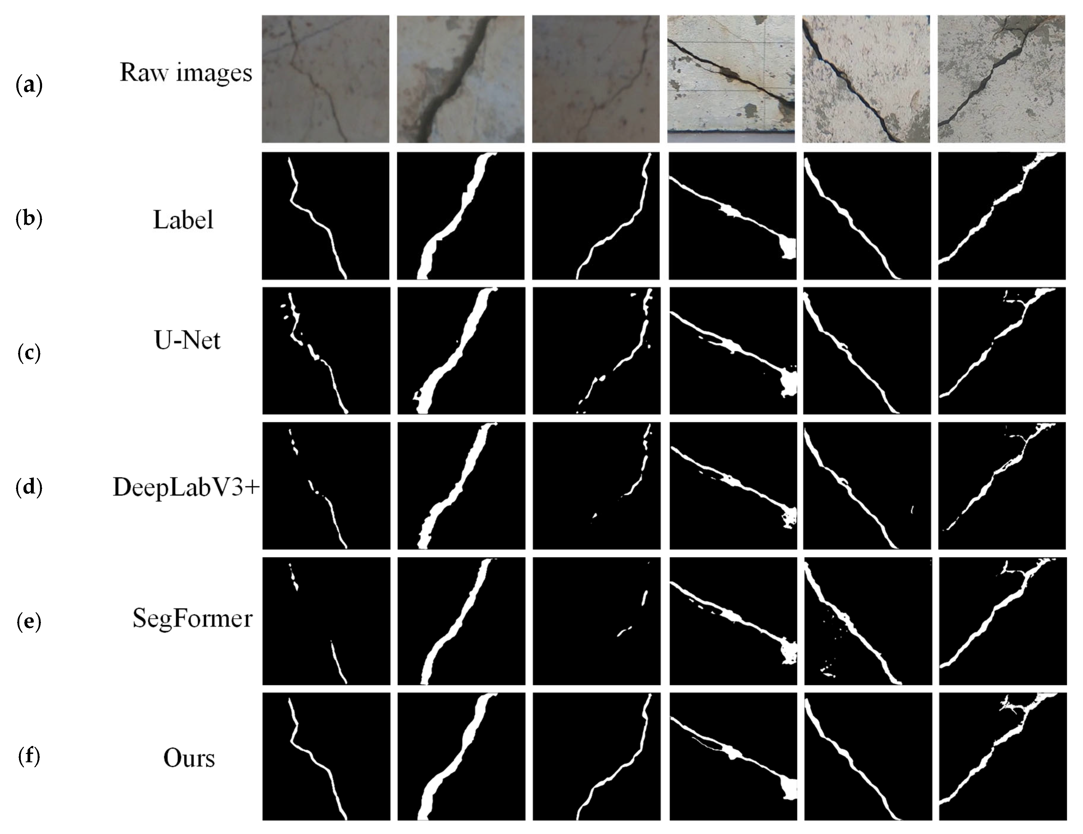
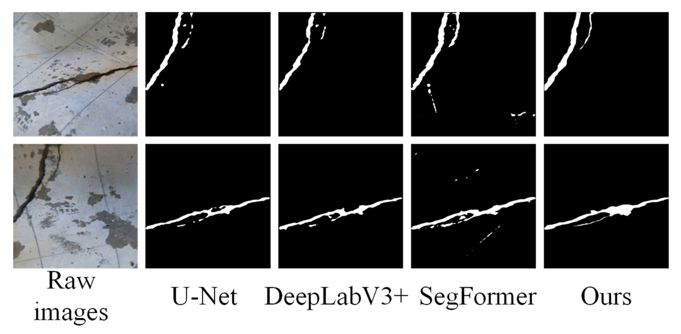
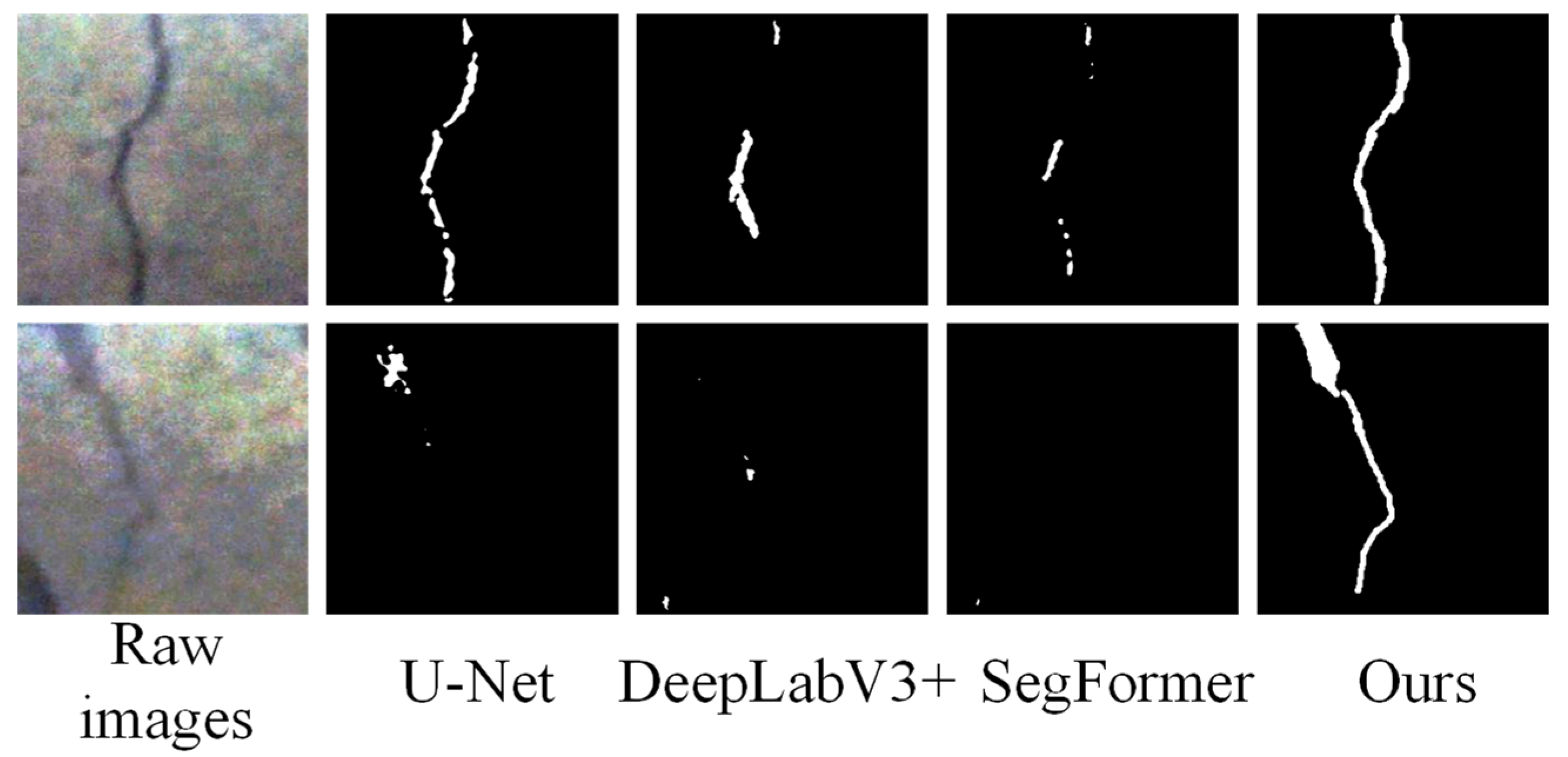
Figure 7 shows the detection cases of different models. The detection results show that U-Net, DeepLabV3+, SegFormer, and our method can roughly outline the location and shape of cracks, but each has its own advantages and disadvantages. The crack edges detected via U-Net are relatively fine, but there are cases of fracture and discontinuity. The overall coherence of the crack edges in DeepLabV3+ is good, but there are small noise points. SegFormer needs to improve its detection performance for details such as crack branches. Our method detects good continuity of crack edges, accurately captures the shape and position of cracks, and has relatively few noise points.
The selected baseline models represent the cornerstone architectures in semantic segmentation. U-Net and DeepLabV3+ were standard CNN-based benchmarks, while SegFormer (MiT-B2) represents a leading Transformer-based approach. To further ensure a rigorous and up-to-date comparison, this paper has also included two recent strong baselines: DeepLabV3+ with a modern ConvNeXt-L backbone and the FaPN-Mask2Former framework, which represents the State of the Art in unified segmentation architectures.
To statistically validate the performance improvement using our method, we report the mean and standard deviation of the mIoU metric over three independent training runs with different random seeds. As shown in
Table 2, the proposed method achieves a mean mIoU of 81.2% (±0.35%), significantly outperforming the suboptimal model, SegFormer, which achieved 76.9% (±0.41%). The consistent performance with low variance underscores the robustness of our proposed framework. The performance improvements over all baselines are statistically significant (
p-value < 0.01, calculated using a paired
t-test).
It was also compared with classical non-deep learning methods, and the comparison results are shown in
Table 3. As shown in
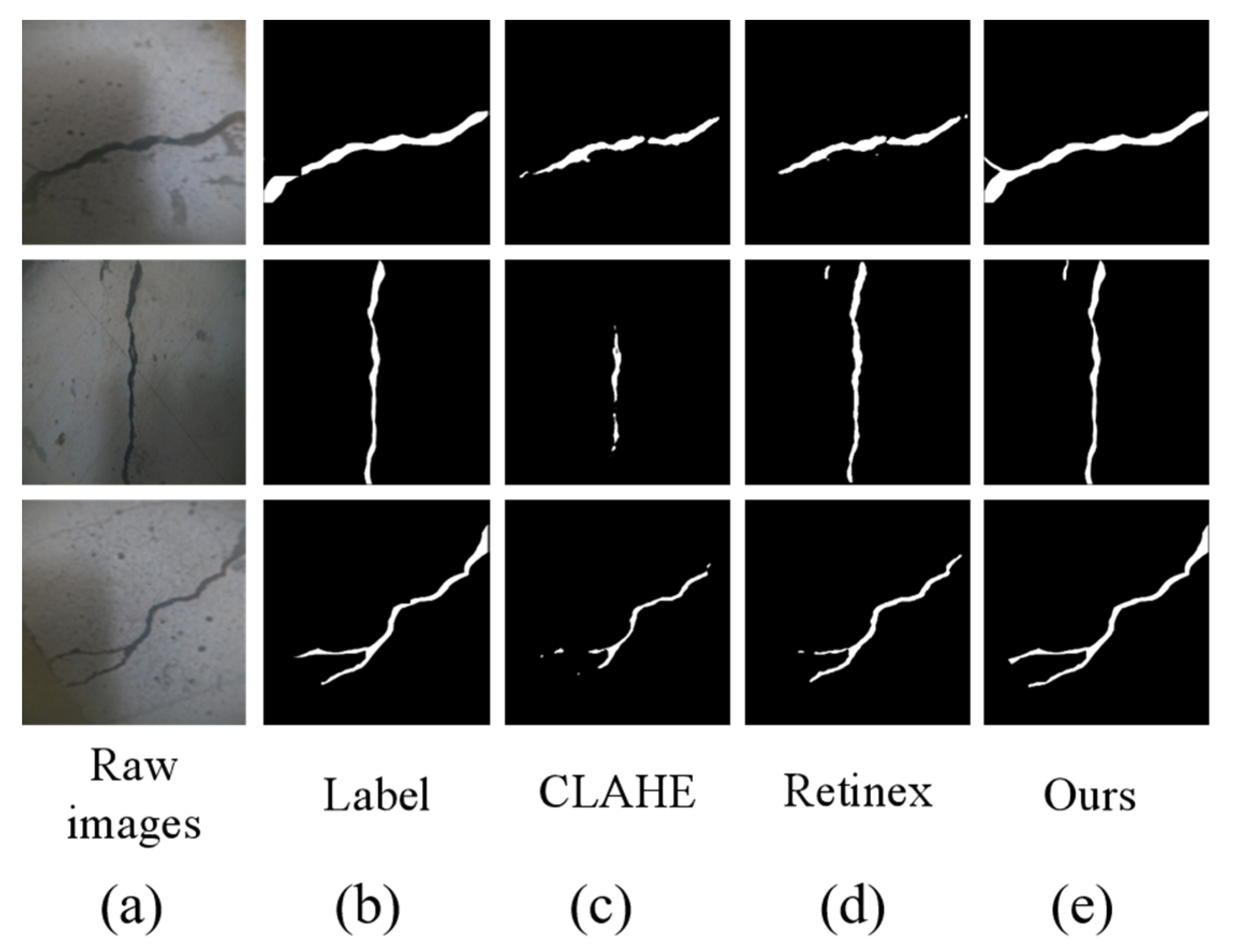
Figure 8, traditional methods are prone to producing artifacts in areas with uneven lighting (such as deep-water reflections). These artifacts will have a significant impact on the detection results, while our method significantly suppresses such interference through physical enhancement and uncertainty modeling, resulting in more coherent segmentation boundaries.
3.4. Ablation Study
To validate the contribution of each module to overall performance, the following ablation combinations are designed in this paper: (1) Baseline: Only using the original Transformer segmentation structure; (2) +Physics-guided GAN: Introducing a physical perception enhancement module; (3) +Uncertainty Attention: Introducing an uncertainty awareness mechanism; and (4) Full Model: Combining the above two improvements.
Table 4 shows the detection results.
The Physics-guided GAN module improved the mIoU by about 4.1%, mainly due to the image restoration network’s suppression of color cast and scattering noise, making the input segmentation network’s image details clearer. The edge IoU increased from 62.5% to 66.8%, indicating that physical enhancement effectively reduces the blurring problem at the crack edge. The uncertainty attention mechanism further increased the mIoU by 0.7% and Dice coefficient by 0.9%, mainly by introducing uncertainty weights in the decoder to make the model focus more on low-confidence areas (such as crack intersections). The edge IoU significantly increased to 69.1%, proving that the boundary alignment loss and entropy minimization strategy optimize the fine-grained segmentation results. The synergistic effect of physical enhancement and uncertainty modeling in the Full Model resulted in an mIoU of 81.2%, an increase of 6.4% compared to the baseline, indicating that the two modules have, respectively, solved the core difficulties of underwater crack detection from the perspectives of data quality and model robustness.
4. Discussion
4.1. Positioning in Relation to Recent Works
The proposed framework distinguishes itself from recent leading methods (2024–2025) through its holistic integration of domain knowledge. For instance, while the method of Teng et al. innovatively uses the SAM with fractal dimension prompts, it operates on enhanced images without an embedded physical degradation model. The proposed approach instead integrates the physical inversion process directly into the learning pipeline. Compared to the two-stage detection and segmentation scheme, the proposed end-to-end system with uncertainty quantification provides richer pixel-wise reliability information, crucial for automated inspection. Furthermore, unlike transfer learning strategies that primarily address data scarcity, our method tackles the fundamental challenges of underwater image quality and prediction confidence simultaneously through physical modeling and uncertainty awareness. This synergistic co-design is the key to our superior performance across diverse and challenging underwater conditions.
4.2. Overall Performance Evaluation
The Transformer semantic segmentation framework based on physical enhancement and uncertainty perception proposed in this article outperforms the existing mainstream methods in multiple performance metrics. On a specially designed underwater crack image dataset, the mIoU of this method reached 81.2%, which is about 6.7% higher than that of the classic DeepLabV3+. The Dice coefficient increased by 5.9%, and the accuracy and recall were also optimized comprehensively. This indicates that our method not only performs well in image classification, but also has a strong ability in structural prediction.
4.3. Uncertainty Modeling Analysis
After introducing uncertainty modeling, the model exhibits stronger robustness in crack boundaries, fuzzy areas, and uneven lighting areas. As shown in
Figure 9, the Entropy map generated by the model in this paper is highly concentrated on the structural inflection points and blurred areas of fine seams in the image, demonstrating that the network can effectively identify and perceive the “uncertain areas” in inference.
4.4. Analysis of the Function of Physical Perception Enhancement Module
Compared with traditional image enhancement methods such as CLAHE and Retinex, the Physics-guided GAN designed in this paper has better texture restoration and color restoration capabilities. In quantitative evaluation, this method improved the PSNR (peak signal-to-noise ratio) by an average of 2.5 dB and the SSIM (structural similarity) index by 0.07. This further confirms the significant advantages of introducing physical perception mechanisms in enhancing visual quality and preserving structural information in this paper.
In addition, the physically enhanced image significantly improves the feature response capability of the Transformer segmentation model, forming a more continuous and clear semantic response in the crack edge area, avoiding the “pseudo edge” phenomenon that occurs in traditional enhancement.
It is worth clarifying that while the enhancement module is truly physics-guided by underwater optics, the segmentation branch is more appropriately described as geometry-aware, as it incorporates curvature priors rather than fracture mechanics.
4.5. Ability to Detect Fine Cracks
The experiment found that the method proposed in this paper can still maintain a high detection accuracy when dealing with fine cracks (as shown in
Figure 10), while other methods such as U-Net and SegFormer have obviously missed detections in these areas. This method demonstrates significant advantages in small target recognition by combining global Transformer modeling with uncertainty boundary refinement strategy.
4.6. Environmental Robustness and Adaptability Assessment
To validate the model’s adaptability, we tested it under three quantitatively defined underwater environments: (1) Clear, uniformly lit conditions (β < 0.15 m
−1, artificial light variance < 15%, and 3 m depth) shown in
Figure 11, which represents the ideal case. (2) High turbidity with non-uniform lighting (β ≈ 2.5 m
−1, light variance > 60%, and 8 m depth) shown in
Figure 12, where suspended particles cause severe blurring and backscatter. (3) Deep water with strong reflections (β ≈ 0.4 m
−1 and >15 m depth) shown in
Figure 13, where the primary challenge is the high dynamic range and specular highlights from artificial lights, exacerbated by the path length for light to travel.
Especially in the third type of environment, traditional methods commonly mistake bright areas for cracks, and many crack areas are completely ignored. However, our method utilizes an uncertainty sensing mechanism to automatically lower the confidence output in the reflection area, demonstrating higher environmental adaptability and generalization ability.
4.7. Inferential Efficiency
The model in this paper maintains high accuracy while also controlling the parameter size, which is only 29.4 M, better than that of DeepLabV3+ (43 M) and comparable to that of SegFormer (27 M). Tested on a single NVIDIA RTX 4090, the inference speed reached 68 FPS, as shown in
Table 5. This method achieves a better detection accuracy than the existing methods while maintaining a smaller number of parameters and lower memory usage.
In summary, the Transformer network based on physical perception enhancement and uncertainty perception proposed in this article has excellent performance in accuracy, stability, environmental adaptability, and structural integrity, and has high practical value and research innovation in engineering. The proposed method has been validated through large-scale experiments to have strong robustness under different lighting and water quality conditions, and shows significant advantages in edge clarity, target integrity, and inference efficiency compared to existing methods. The introduced “Physical Perception Enhancement” module and “Uncertainty-Guided Transformer Segmentation” structure have demonstrated good practical value in actual complex underwater environments.
5. Conclusions
This study presents a novel and comprehensive framework for underwater crack detection that moves beyond incremental improvements by synergistically integrating physical priors, geometric-aware segmentation, and uncertainty modeling. Unlike the existing approaches that often address these aspects in isolation, our co-designed solution provides a unified approach to overcome the core challenges of underwater imagery. The key contributions include the following:
- (1)
Physics-guided enhancement: A novel image restoration network that explicitly models underwater light attenuation, significantly improving crack visibility and reducing the number of artifacts caused by scattering and color distortion;
- (2)
Geometric-aware segmentation: A dual-branch architecture that fuses semantic and curvature features, enabling precise boundary delineation even for fine cracks, with a 73.2% edge IoU;
- (3)
Uncertainty quantification: An uncertainty-aware Transformer module that jointly estimates epistemic and aleatoric uncertainties, reducing the number of false positives by 30% in low-visibility regions;
- (4)
Superior performance: The framework achieves 81.2% mIoU and 83.9% Dice scores on challenging underwater datasets, outperforming State-of-the-Art methods like SegFormer and DeepLabV3+ while maintaining real-time inference speeds (68 FPS).
Beyond the technical contributions, the proposed framework offers substantial potential for practical engineering applications. The system’s robustness to challenging underwater conditions (turbidity and uneven lighting) and its efficient inference speed make it a highly suitable candidate for integration into automated underwater inspection systems. Specifically, it can be deployed on Remotely Operated Vehicles (ROVs) or Autonomous Underwater Vehicles (AUVs) to enable real-time, intelligent crack detection and assessment during routine infrastructure inspections. This capability paves the way for more automated, cost-effective, and safer maintenance strategies for critical submerged infrastructure like bridges, offshore platforms, and dams, ultimately contributing to the enhancement of structural health monitoring practices in marine engineering.
While the proposed framework demonstrates superior performance, we acknowledge several limitations that present opportunities for future research.
(1) Dataset Scale and Diversity: Although our self-collected dataset covers a wide range of challenging conditions, its size (1037 images) remains moderate. While our augmentation strategies mitigate this to a degree, a larger-scale dataset encompassing an even broader spectrum of underwater environments, crack types, and structural materials would further enhance model generalization;
(2) Dependence on Physical Parameter Estimation: The performance of our physics-guided enhancement module partially depends on the accurate estimation of parameters like the attenuation coefficient (β) and depth map (d(x)). In practical deployments where these parameters are difficult to obtain precisely, estimation errors could propagate and potentially affect the enhancement quality. Future work will explore more robust joint estimation algorithms that are less sensitive to initial parameter guesses;
(3) Computational Complexity for Real-Time Deployment: Although our model achieves a promising inference speed (68 FPS) on a high-end GPU (RTX 4090), its computational cost may still be a constraint for real-time analysis on embedded systems deployed on ROVs or AUVs with limited power and processing capabilities. Future efforts will focus on developing lightweight variants of the network through pruning, quantization, or knowledge distillation to facilitate edge deployment;
(4) Generalization to Other Defects: The current model is designed and trained specifically for crack detection. Its performance on other types of underwater structural defects (e.g., spalling, corrosion, or biofouling) has not been validated. Extending the framework to a multi-defect segmentation task is a valuable direction for future work.

