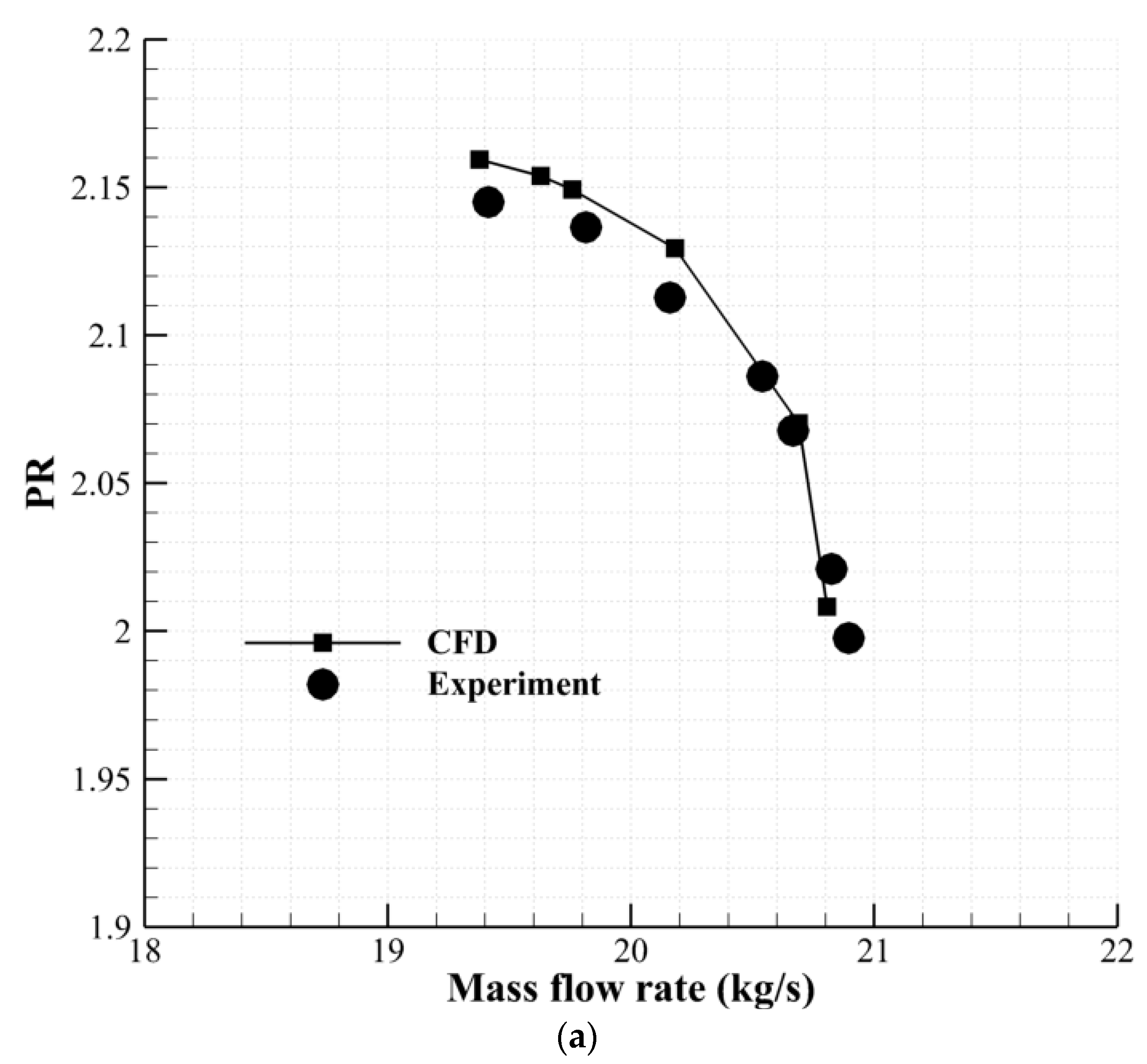
1. Introduction
Efforts to improve gas turbine engine performance while reducing size and weight have resulted in more complex turbomachinery flows [
1], stability problems [
2,
3,
4,
5,
6,
7], and manufacturing and assembly issues [
8]. The design point of aero compressors is typically located far enough from the stall point to prevent rotating stall and surge [
9]. Significant efforts have been dedicated to postponing the occurrence of these compressor aerodynamic instabilities, by using active and passive stall control methods. Casing and blade treatments are two passive approaches for enhancing compressor stability. Different types of casing treatment have been studied experimentally and numerically by a number of researchers [
10,
11,
12]. The most effective efforts have used circumferential grooves or axial slots over the compressor endwall casing. Smith and Cumpsty [
13] published the results of an experimental study on an axially skewed slot casing treatment. The slots had a total open area of about 0.7 and were inclined to the radial direction at a 60 degree angle. They showed that the provision of a flow path between the pressure and suction surfaces was the main impact of the casing treatment that causes compressor range extension. Emmrich et al. [
14] explored axial and radial skewed slots in a high subsonic compressor experimentally. A 50 percent increase in operating range was attained at the penalty of a 1.4 percent decrease in compressor efficiency. A numerical investigation on axial skewed slot casing treatment on a low-speed compressor was conducted by Crook et al. [
15]. They discovered that the slots avoided stall through two primary effects: suction of the low total pressure fluid at the rear of the passage and energizing of the tip leaking flow.
Blade treatment is another passive approach that has been suggested by some researchers recently (e.g., blade tip winglet, tip squealer, etc.). Gourdain and Leboeuf [
16] simulated an axial compressor with casing and blade treatments. Casing treatment with nonaxisymmetric slots demonstrated adequate control of tip leakage flow but did not improve boundary layer separation on the suction side. Nonetheless, an improvement in operability was achieved, with a penalty in efficiency. They also studied blade treatment, which consisted of a longitudinal groove at the tip of each rotor blade. Their results revealed that the treatment could control a majority of end wall flow, while the efficiency remained constant. They concluded that the blade treatment could be more effective than the casing treatment method. Ding et al. [
17] studied the influence of boundary layer suction holes created on the suction surface of a compressor cascade with a large camber angle, numerically and experimentally. The findings showed that both the side and middle suctions on the suction surface could efficiently remove low-energy fluid, hence increasing cascade load capacity, while successfully preventing corner flow separation. The aerodynamic efficiency of the cascade was clearly increased by center and side suctions, and it was also influenced by changes in suction location. The best location for middle suction holes was found to be 60–66 percent chord from the leading edge, whereas the optimum position for side suction holes was a bit downstream of the corner separation line. Chen et al. [
18] investigated the effect of boundary layer suction on flow characteristics in a highly loaded compressor cascade (with clearance). Different positions and distributions of suction holes were investigated. Results showed that boundary layer suction could reduce tip clearance flow losses. Zhao et al. [
19] conducted numerical research on the tip winglet and its influence on the stability of a high-load compressor stage. The results showed that the winglet chordwise thickness distribution had a significant impact on improving the stage operating range. They showed that the winglet reduces leakage mass flow by accelerating the flow at the tip of the blade, increasing the axial momentum while decreasing the circumferential momentum of the flow. The stall margin was increased by 25.39% in the optimum winglet case. Cui et al. [
20] investigated the effect of the pressure-side winglet on the stall margin of NASA Rotor-37. The simulations suggested that the pressure-side winglet had a considerable impact on the operating range and maximum efficiency of the rotor. The winglet had the same efficiency compared to the baseline and did not cause any appreciable aerodynamic losses at the blade tip. Furthermore, the results demonstrated that the optimum winglet reduced tip leakage mass flow by 20% while increasing operating range by 15%. Ji-bo et al. [
21] studied the impact of four different winglets at the tip of the NASA Rotor-37. All of the winglets extend the rotor’s operating range; however, the findings showed that the suction-side winglet was more effective than the pressure-side one. The best suction-side winglet increased the stability margin by 4.93% while maintaining the efficiency fixed. Syka et al. [
22] analyzed the influence of the so-called technological holes in a centrifugal compressor numerically. They demonstrated that in some specific cases, improper design of technological hole diameter, position, or orientation might result in substantially reduced performance parameters. Zhang et al. [
23] controlled flow separation in a highly loaded compressor cascade using unsteady pulsed suction through endwall bleeding holes. The optimum excitation frequencies were found to be integer multiples of vortex shedding’s natural frequency. Matas et al. [
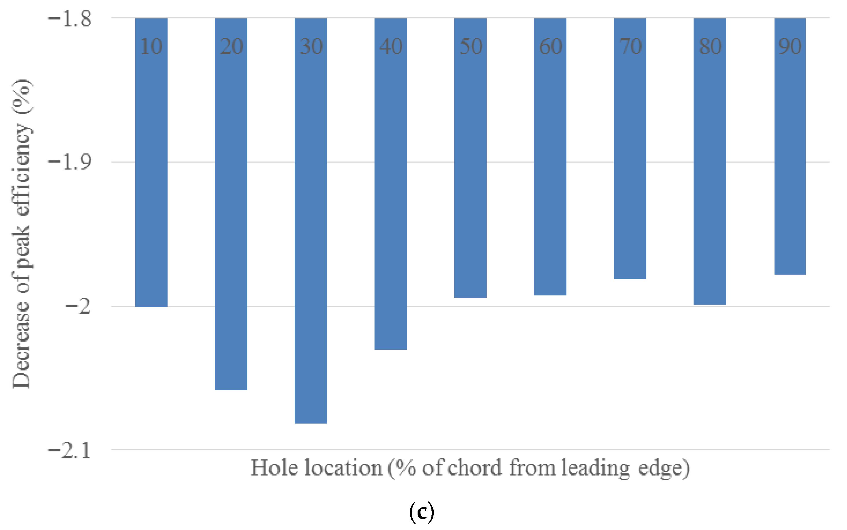
24] investigated the effect of technological holes on the performance of a centrifugal compressor experimentally and numerically. The simulation results with the technical holes showed a very small influence on the pressure characteristic and mass flow rate. Furthermore, efficiency was decreased by up to 1.8%, depending on the position of the holes. Jung et al. [
25] evaluated the impacts of a recessed blade tip on NASA Rotor-67. They demonstrated that the depth and length of the recessed blade tip can increase the rotor stall margin. They showed that a strong vortex was formed in the recess cavity, reducing the tip leakage flow. The best recess cavity increased the stall margin by 0.4% while keeping the efficiency unchanged. Tang et al. [
26] used blade-end slots to reorganize the flow at the blade ends of a highly loaded compressor cascade with a large incidence range. The findings demonstrated that the proposed method efficiently suppressed corner separation while also broadening the effective operating range. Flow details further showed that the blade end slots could create self-adaptive high-momentum jet flows, due to the pressure difference between the blade pressure and suction surface.
The main objective of this study is to investigate a novel blade treatment method on a high-speed axial flow compressor rotor. The treatment includes making special holes in the blade and near the tip section. Furthermore, the influence of the streamwise location and the angle of the holes is investigated in this research.
The blade treatment investigated in this study incorporates a circular hole located near the blade tip. When positioned at an appropriate location and angle, this hole is expected to displace the shock wave downstream within the rotor passage, thereby extending the rotor’s operating range. Furthermore, the hole reduces the pressure difference between the pressure and suction sides, resulting in decreased blade loading near the blade tip. This effect, coupled with the momentum transfer from the pressure to the suction side, contributes to an increase in rotor operating range. It should be noted that this method has been investigated on an isolated rotor. Further studies are required to extend this method to multi-stage compressors. In addition, the effectiveness of this method may differ in subsonic compressors.
4. Results and Discussion
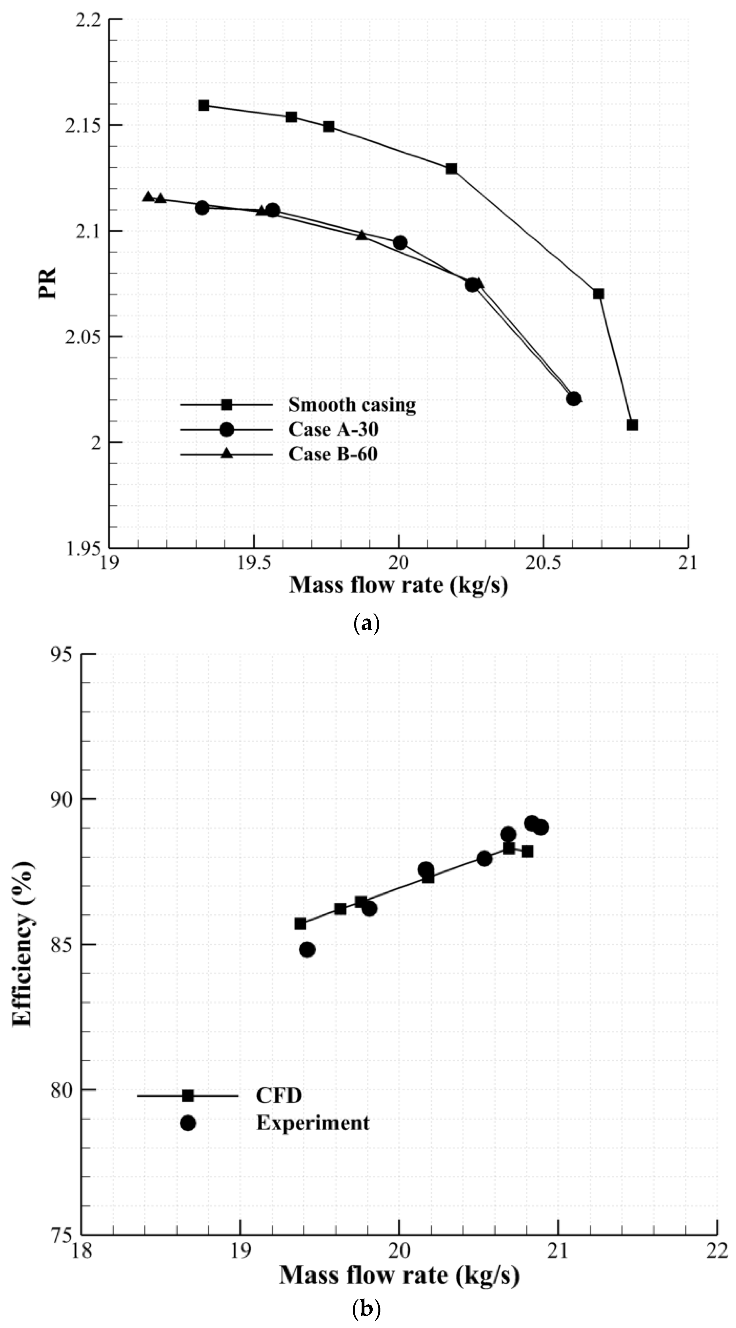
In order to investigate the importance of the hole angle, Case A-30 and Case B-60 have been simulated first. As was specified in
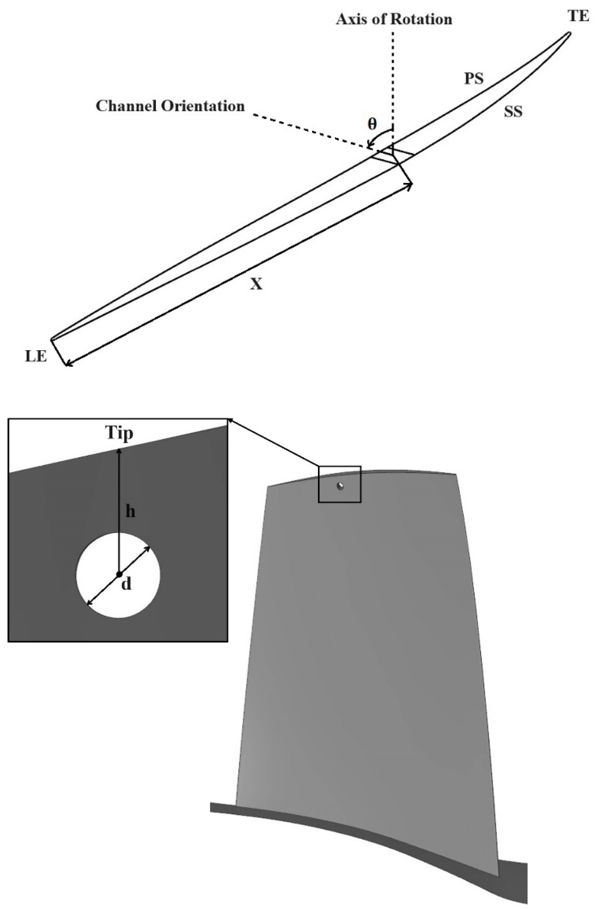
Table 2, in Case A-30 and Case B-60, the hole is located at 60 percent chord. However, in case A-30, the hole angle with respect to the axis shown in
Figure 1 is 30 degrees (the hole is almost perpendicular to the blade surface), whereas in Case B-60, the hole angle is 97.5 degrees.
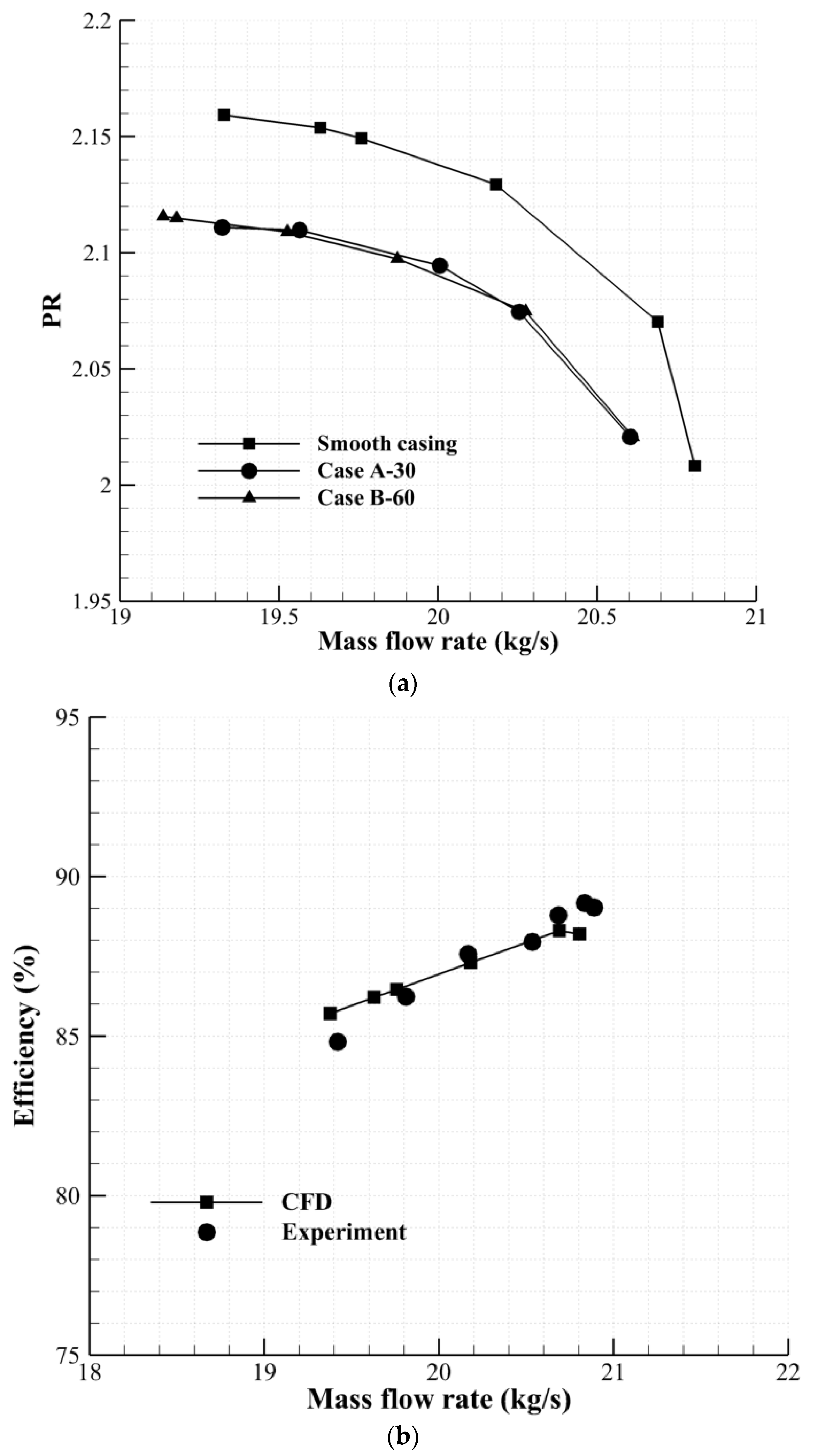
Figure 5 shows the performance curves of the two mentioned configurations. As can be seen in these figures, Case A-30 has slightly decreased (−1.5% based on Equation (3)) the operating range of the rotor. However, case B-60 shows considerable range extension (11% based on Equation (3)). Note that the operating range variation for all cases was calculated using Equation (3).
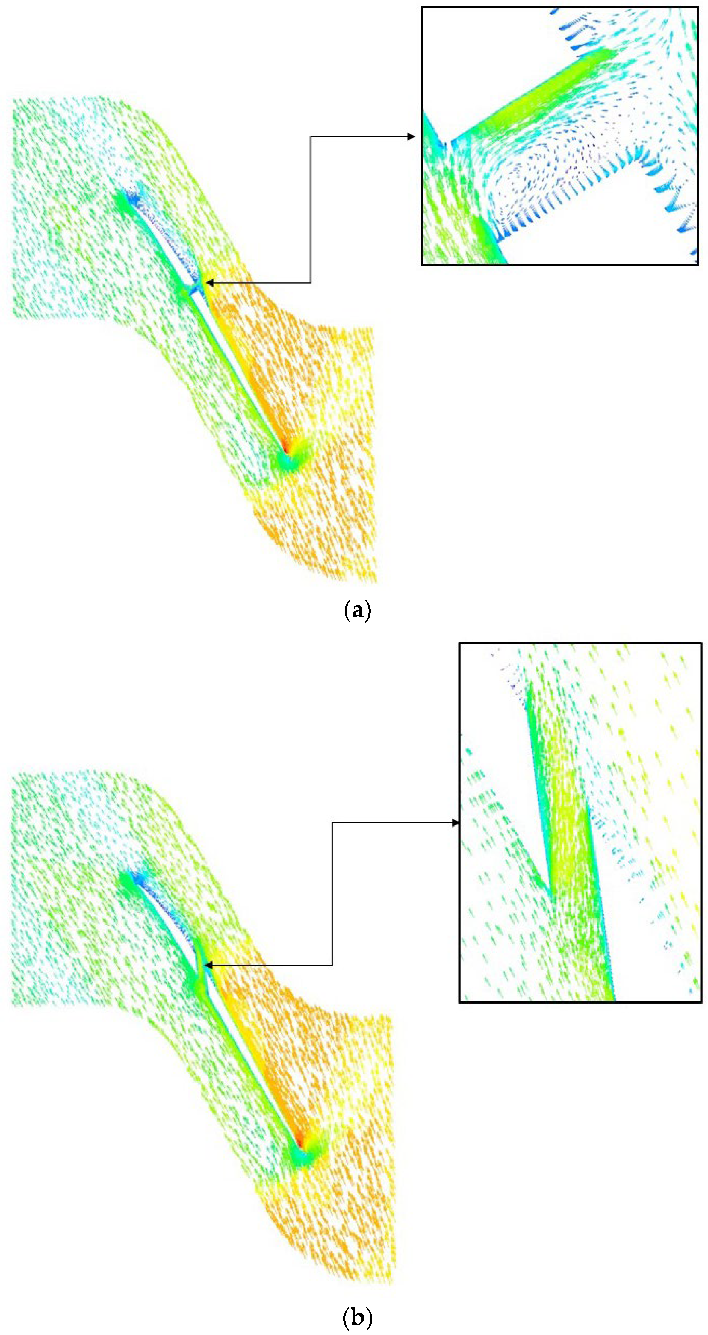
Figure 6 depicts the flow vectors shown on a surface passing through the middle height of the hole for Cases A-30 and B-60. As shown in
Figure 6a, in Case A-30, a vortex has been formed in the hole, which blocks the hole flow. However, in Case B-60, where the hole angle has been increased to 97.5 degrees, the vortex has been removed and the endwall air can flow from pressure to suction side almost uniformly, resulting in rotor range extension.
As shown above, the angle of the hole has an important effect on the operating range of the rotor. So, in this section, the hole angle is kept constant (at 97.5 degrees) and the effects of hole location on the performance of the rotor are studied.
As mentioned earlier, a parametric study of the effect of the hole’s streamwise location on the compressor performance and operability has been performed in this investigation. As shown in
Table 2, the streamwise location of the hole varied from 10 to 90 percent tip chord from the blade leading edge (Cases B-10 to B-90). Note that in these configurations, the hole angle is kept constant (at 97.5 degrees). Numerical computations have been performed from choke to near-stall for all of the configurations.
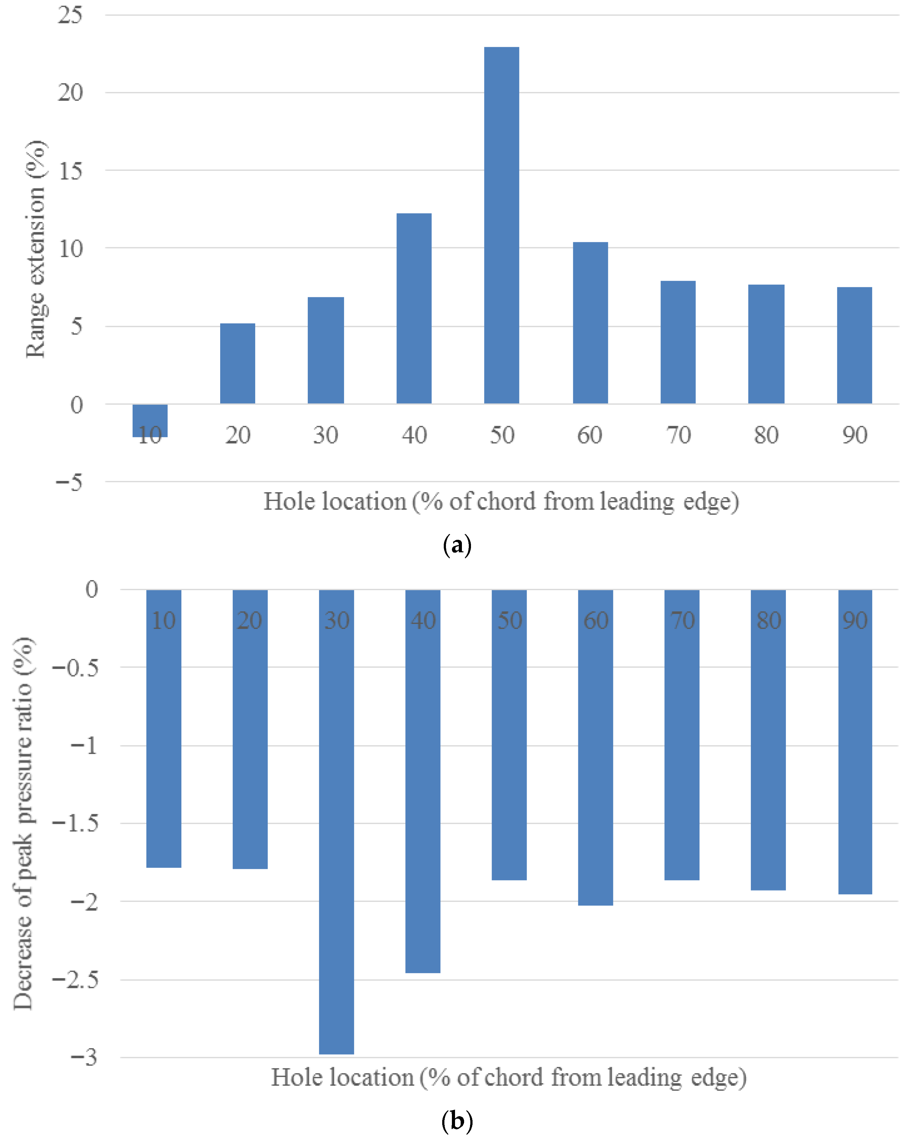
Figure 7 illustrates the effect of the hole position on the compressor performance (in terms of the change in the compressor operating range, peak pressure ratio, and peak efficiency). As shown in
Figure 7a, case B-10 (in which the hole is located near the blade leading edge), reduced the operating range by 3.5 percent. Moving the hole toward the blade trailing edge from 10 to 20 percent chord location (Case B-20) provides about 5 percent range extension. Increasing the distance between the hole center and the blade leading edge up to 50 percent chord is beneficial to rotor stability. Maximum range extension is achieved for Case B-50, which is equal to about 23 percent. However, behind the 50 percent chord location (Cases B-60 to B-90), the operating range extension is smaller, varying between about 11 and 7 percent. According to
Figure 7b, the treatment applied has reduced the rotor peak pressure ratio in all of the configurations. This reduction in the peak pressure ratio is approximately the same for different configurations (between 1.8 and 2 percent reference to the smooth blade), except Cases B-30 and B-40, for which the pressure loss is larger (2.5 to 3 percent). As will be shown later, the main reason is the shock-hole interaction near the stall-point condition. The rotor adiabatic efficiency also decreases in the treated configurations, as illustrated in
Figure 7c. Note that the maximum efficiency loss in different hole positions varies from 2 to 2.1 percent.
In summary, it can be stated that the hole can increase rotor stability (at the expense of some loss in the peak pressure ratio and efficiency), except when located close to the blade leading edge. Furthermore, there is an optimum location with maximum stability enhancement, which is at 50 percent chord in the current study.
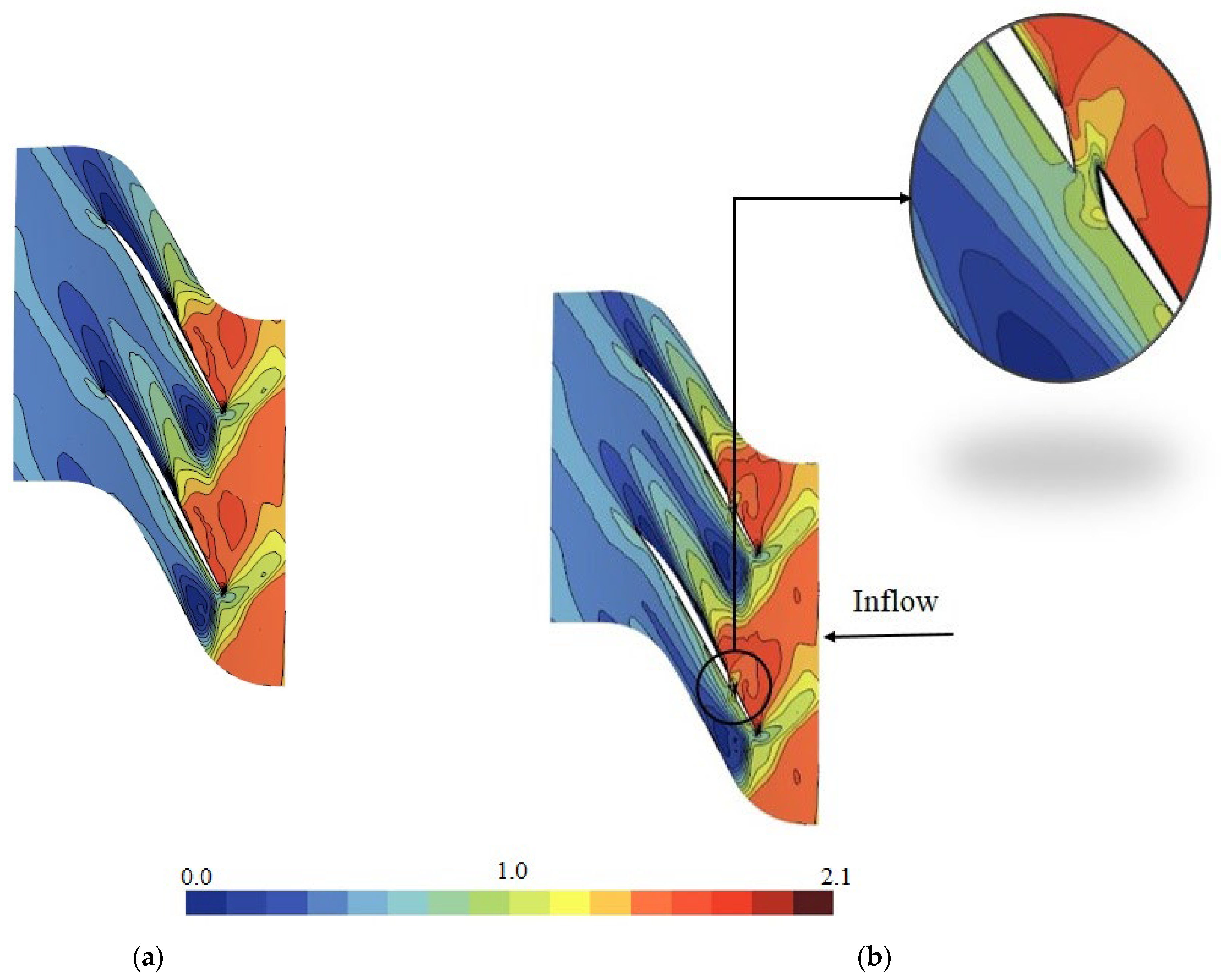
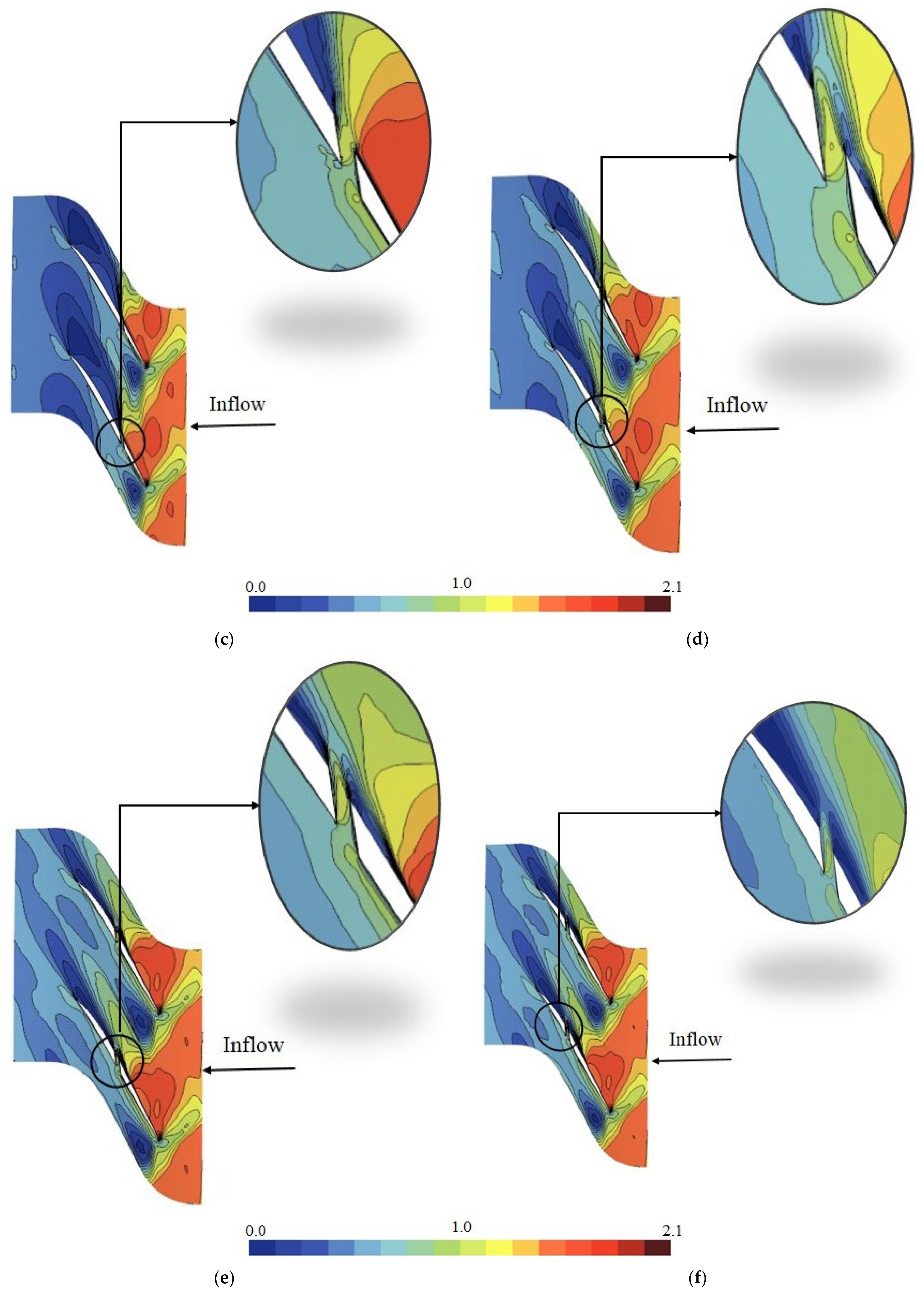
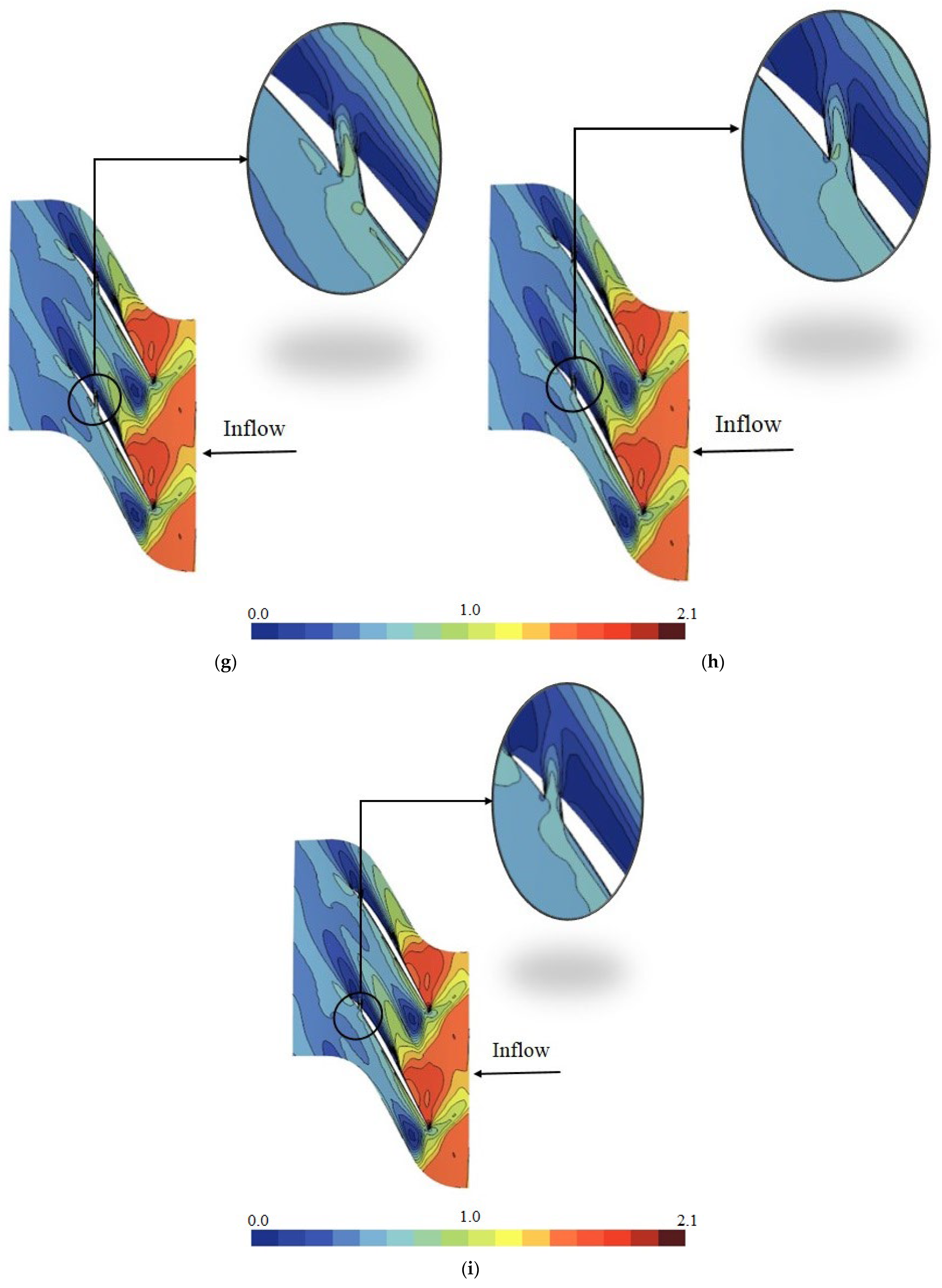
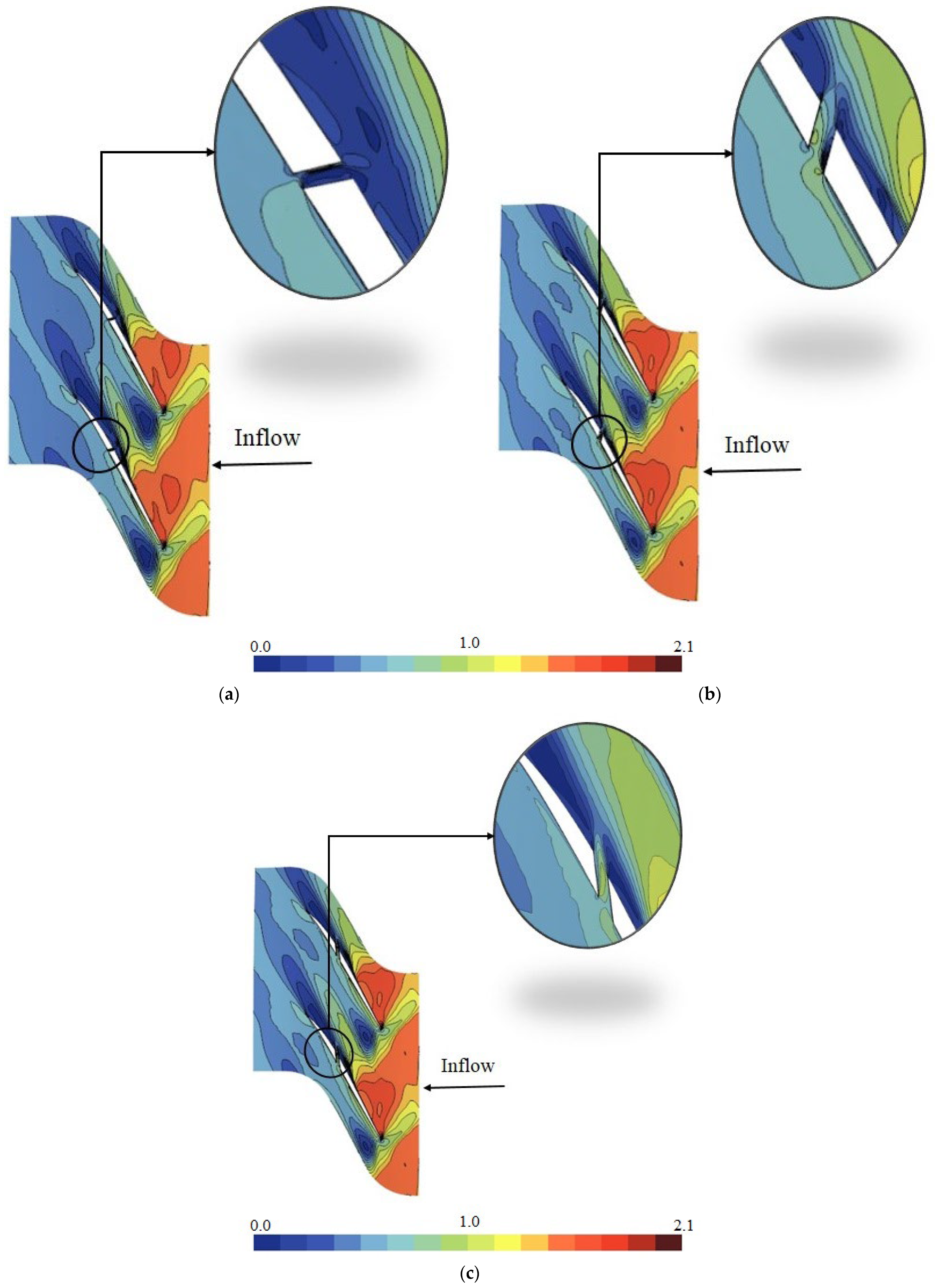
In order to uncover the causes of the above results and to investigate the flow mechanisms leading to operating range improvement, relative Mach number contours are shown at the center plane of the hole in
Figure 8. The smooth blade and Cases B-20 to B-90 are illustrated in this figure. In order to study the effect of the hole, all of the cases should be taken at the same mass flow rate. Therefore, the contour plots in
Figure 8 are all taken at the near-stall mass flow of the smooth blade. Case B-10 is not shown because its near-stall point is at a higher mass flow compared to the smooth blade. In addition,
Table 3 depicts the mass flow rate passing through the hole for all of the cases. According to
Table 3, the hole mass flow rate has decreased from Case B-10 to B-90. Given that the maximum mass flow rate is provided by Case B-10, one may think that this configuration should give maximum stability. However, as shown in
Figure 7, Case B-10 reduces the operating range compared to the smooth blade. The reason is that the blockage occurred on the pressure side due to the hole flow. Although Case B-20 shown in
Figure 8b creates some blockage on the pressure side of the blade, the shock is pushed downstream as compared to the smooth blade due to the hole flow (compare the location of the shock wave on the suction side in Case B-20 and the smooth blade). When the hole is moved toward the blade trailing edge in Case B-30, the pressure drop caused by the hole flow sucks the shock wave. This effect moves the shock upstream and leads to shock–hole interaction. As illustrated in
Figure 8c, the shock structure becomes different in this case. It should be noted that moving the shock upstream in the passage is generally a negative effect (if occurring due to an increase in the back pressure), because the shock strength increases. However, the story is different in Case B-30, because the shock has moved upstream due to the suction provided by the hole (and not due to back pressure). Therefore, the shock becomes more oblique and its strength reduces, resulting in some range extension (about 7 percent as was shown in
Figure 7). Moving the hole from 30 percent chord to 40, pulls the shock downstream in the passage, increasing the amount of range extension to about 12.2 percent. In the best configuration (Case B-50 which is shown in
Figure 8e), the hole is located slightly after the passage shock. The pressure contours show that the shock has moved downstream in Case B-50, compared to the smooth blade, which is due to the hole suction. Furthermore, the separated region on the suction side and near the blade tailing edge is comparatively smaller in Case B-50. The reason is that the hole is located just after the shock wave, and therefore can more effectively control the flow separation, as compared to Case B-30 or B-40. In Case B-60, the stability has been decreased because the effect of the hole on the shock wave has decreased, hence the shock has moved upstream, as compared to Case B-50. When the hole moves away from the shock wave in Cases B-70 to B-90, the effect of the hole on the shock decreases (as compared to Case B-60) and remains constant for these cases.
It is worth mentioning that in
Table 3, the mass flow rate of the hole abruptly decreases between Case B-30 and B-40, which is due to the shock–hole interaction.
In this section, the blade loading is investigated to provide a more detailed analysis of the flow physics described above.
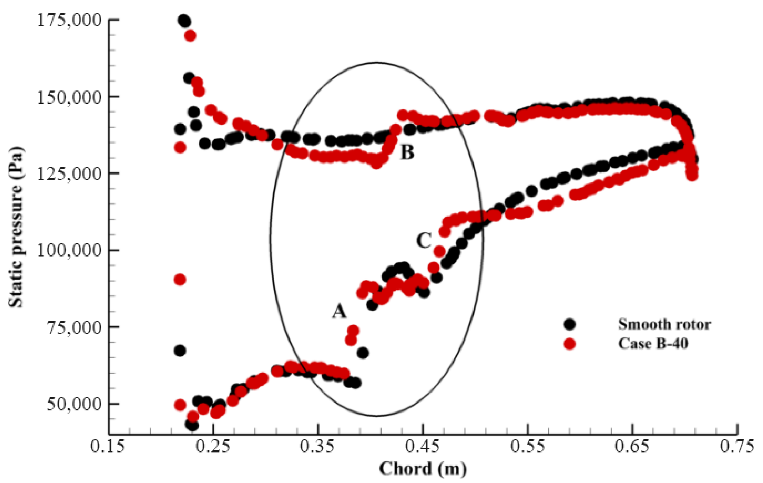
Figure 9 illustrates the blade loading at 99% span for both the smooth blade and Case B-40. Note that the hole center is located at 96.75% span. As can be seen, the hole has led to a decrease in blade loading upstream of its location near the leading edge. The reduction in blade loading, particularly near the leading edge, has enhanced rotor stability. The location of the hole is specified in
Figure 9. Region A refers to the upstream edge of the hole that interacts with the shock waves on the blade suction side. Region B explains the impact of the passage shock passing through the hole on the blade’s pressure surface, resulting in a sharp pressure rise in Case B-40. Note that the shock wave in the smooth rotor does not interact with the pressure surface, and therefore, no sudden pressure rise is observed on the pressure surface (compare the relative Mach number contours on the pressure surface and near the hole in
Figure 8a,d). The downstream edge of the hole is indicated by Region C. A sudden pressure rise occurs in this region (compare it with the smooth rotor). This sudden pressure rise indicates the influence of the shock wave interacting with the downstream edge of the hole, as depicted in
Figure 8d. The comparison of the smooth rotor loading with that of Case B-40 reveals that initial shock waves formed more rapidly in Case B-40. Comparison of the smooth rotor and Case B-40 reveals that shock waves formed earlier in Case B-40. In contrast, the smooth rotor experienced a sudden, stronger shock. In Case B-40, the shock dispersed more than in the smooth rotor (compare
Figure 8a,d). So, the shock moved until the downstream edge of the hole in Case B-40, which reduced the shock strength and pushed the shock waves back more than in the smooth rotor.
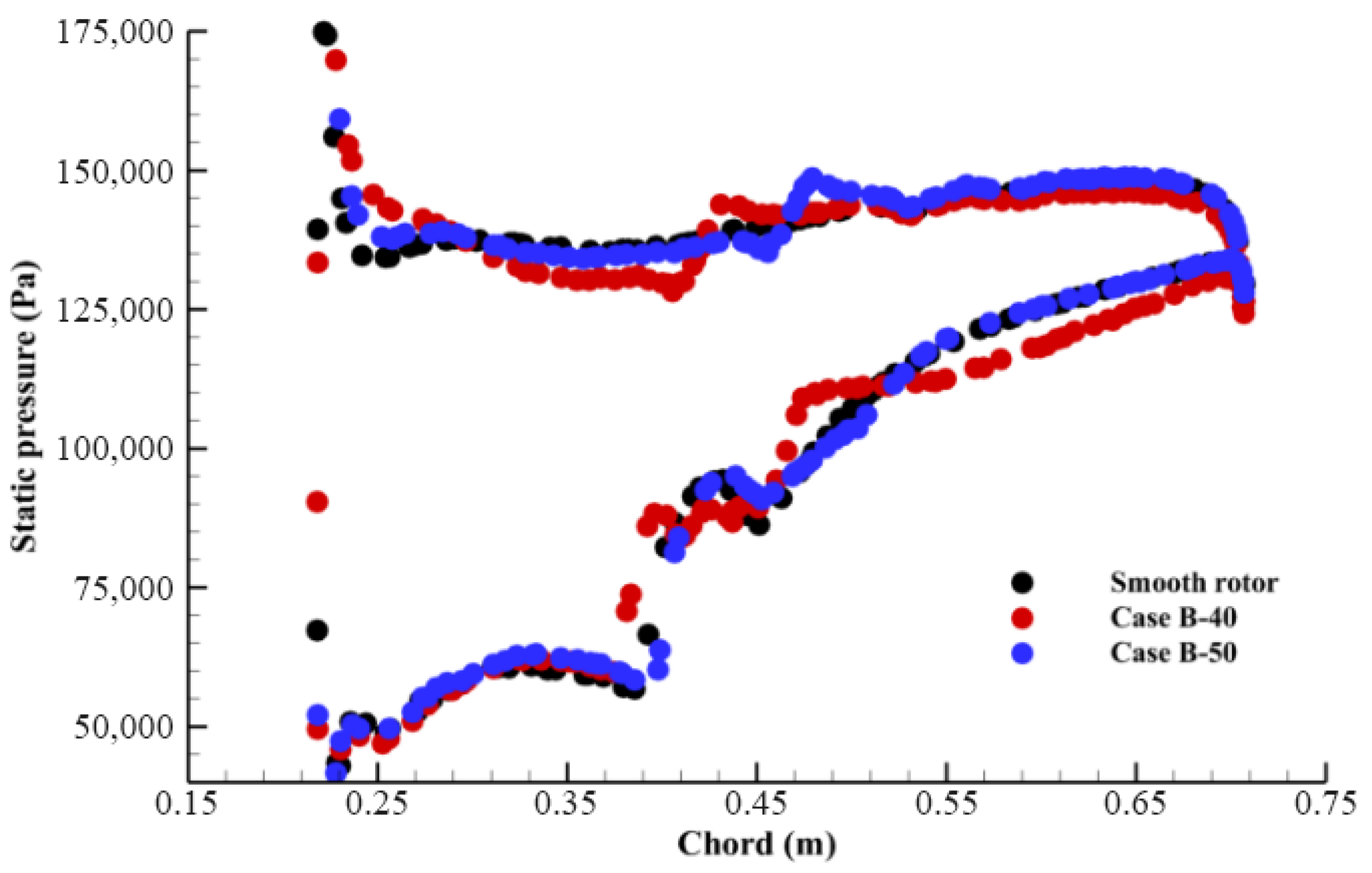
Figure 10 provides a comparison of the blade loading for Cases B-40, B-50, and the smooth rotor at 99% of the blade span. This figure compares the blade loading between Case B-40 and Case B-50, highlighting the reduction in blade loading near the trailing edge and after the hole in Case B-50. The reason for this is that in Case B-50, the shock occurred before the hole, and the hole does not affect the upstream flow. As shown in the figure, unlike Case B-40, the shock wave in Case B-50 moved downstream 3.56% relative to the smooth rotor (compare
Figure 8d,e).
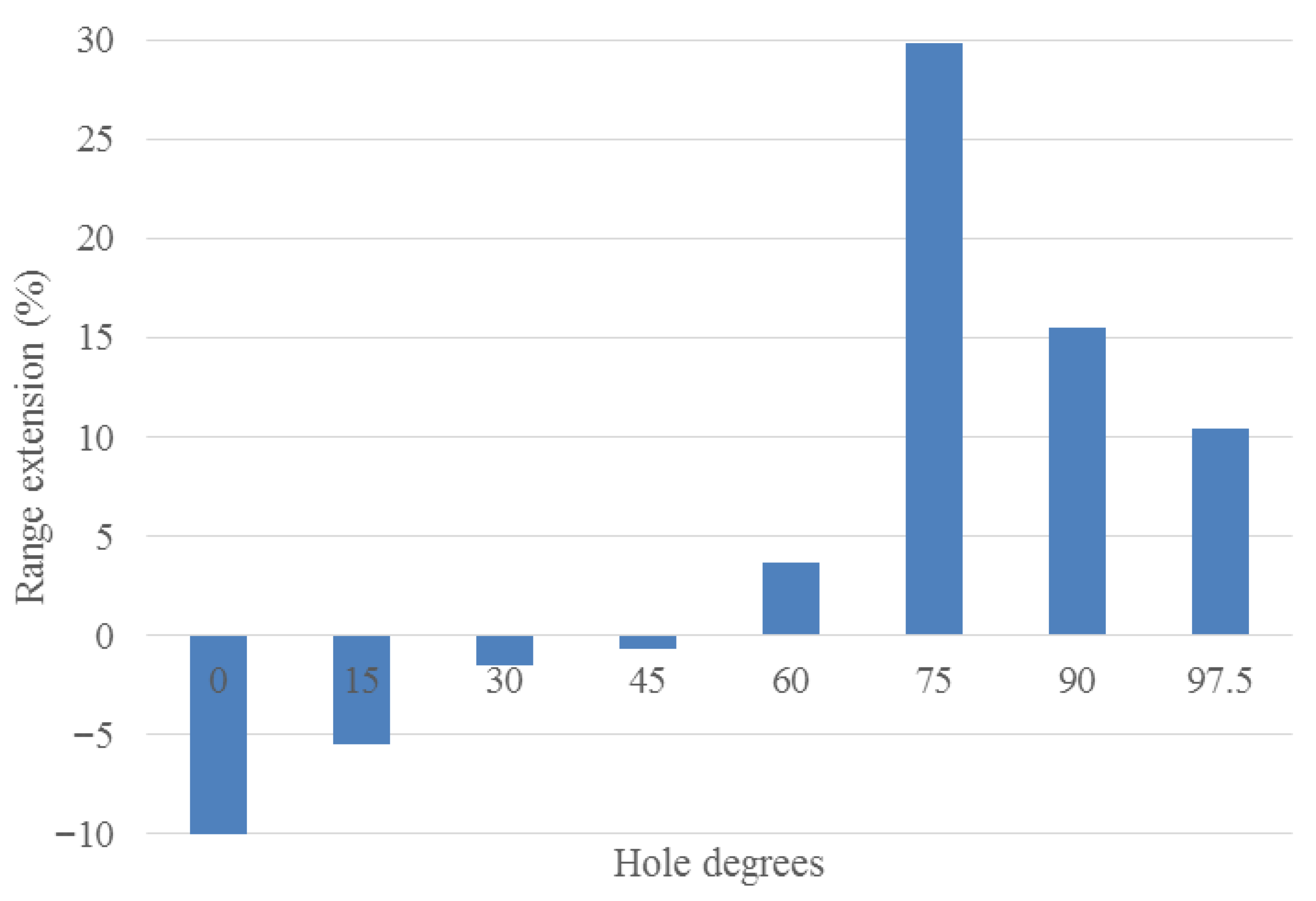
The angle of the hole is one of the key parameters, as demonstrated earlier (the comparison between Case B-60 and Case A-75 in
Figure 11). In order to evaluate the effect of the hole angle on rotor performance, the angle of Case B-60 varied from 0 to 97 degrees. Case B-60 is carefully chosen based on the above results, because maximum range extension was achieved when the hole could effectively pull the shock wave back. On the other hand, the effectiveness of Case B-60 was less than that of Case B-50. Therefore, the goal is to determine whether or not changing the hole angle can further pull the shock wave back.
Figure 11 depicts the impact of the hole angle for the mentioned configurations. As shown in this figure, the angle of the hole has a significant effect on rotor operability. The amount of stability enhancement in Case A-75 (the hole is located at 60 percent chord, and its angle is 75 degrees) is significantly greater than in the others. In order to explain this finding, the relative Mach number contours are plotted for Cases A-15, A-75, and B-60 in
Figure 12. These cases are shown at the near-stall condition of the smooth blade, except Case A-15, which is depicted at its stall point (because its stalling mass flow is greater than that of the smooth blade). In Case A-15, the injecting flow has increased the blockage on the blade suction side, which consequently reduces the rotor operating range (the same occurs in Cases A-0 to A-45). When the hole angle is increased (greater than 45 degrees), the stability also increases. Maximum stability is achieved in Case A-75 (approximately 30%).
Figure 12 shows that Case A-75 has further pulled the shock back in the passage, as compared to Case B-60.
Additionally, Case A-75 enhances the operating range more than Case B-50.
Figure 13 compares the characteristic curve of Case A-75 and Case B-50 (the best configurations in terms of operating range extension). Referring back to
Figure 7, with a hole angle of 97 degrees, the best configuration was Case B-50 (in terms of stability). However, Case A-75 appears to be more stable than Case B-50. This emphasizes the importance of the hole angle.
Table 4 illustrates the mass flow rate through the holes for different configurations (at the same mass flow rate corresponding to the stalling condition of the smooth blade). As shown in
Table 4, the mass flow rate through the hole is nearly constant for Cases A-0 to A-45, but for hole angles greater than 60 degrees (Cases A-60 to Case B-60), the mass flow rate increases as the hole’s angle increases. The reason is the formation of a vortex within the hole, which blocks the passing flow, as shown in
Figure 6a for Case A-30. By increasing the hole angle, the size of the formed vortex reduces, so that in Case A-90 and Case B-60 (hole angle equal to 90 and 97 degrees, respectively), the vortex has been removed. However, as previously stated, Case A-75 significantly improves rotor stability over Cases A-90 and B-60. The reason is more passage suction (hence more backward movement of the shock wave) provided by Case A-75, as compared to Case B-60.
