Article

Energy-Efficient Hybrid Wireless Power Transfer Technique for Relay-Based IIoT Applications

by
Vikash Singh
1,*,
Roshan Kumar
2,
Byomakesh Mahapatra
1,* and
Chrompet Ramesh Srinivasan
1,*
1
Department of Instrumentation and Control Engineering, Manipal Institute of Technology, Manipal Academy of Higher Education, Udupi 576104, India
2
Department of Electronic and Information Technology, Miami College, Henan University, Kaifeng 475004, China
*
Authors to whom correspondence should be addressed.
Designs 2024, 8(5), 84; https://doi.org/10.3390/designs8050084
Submission received: 19 June 2024 / Revised: 22 July 2024 / Accepted: 2 August 2024 / Published: 26 August 2024

Abstract

:
This paper introduces an innovative hybrid wireless power transfer (H-WPT) scheme tailored for IIoT networks employing multiple relay nodes. The scheme allows relay nodes to dynamically select their power source for energy harvesting based on real-time channel conditions. Our analysis evaluates outage probability within decode-and-forward (DF) relaying and adaptive power splitting (APS) frameworks, while also considering the energy used by relay nodes for ACK signaling. A notable feature of the H-WPT scheme is its decentralized operation, enabling relay nodes to independently choose the optimal relay and power source using instantaneous channel gain. This approach conserves significant energy otherwise wasted in centralized control methods, where extensive information exchange is required. This conservation is particularly beneficial for energy-constrained sensor networks, significantly extending their operational lifetime. Numerical results demonstrate that the proposed hybrid approach significantly outperforms the traditional distance-based power source selection approach, without additional energy consumption or increased system complexity. The scheme’s efficient power management capabilities underscore its potential for practical applications in IIoT environments, where resource optimization is crucial.
Keywords:
WPT; IIoT; SWIPT; APS

1. Introduction

The next-generation industry is enabled with different digital devices starting from the raw material extraction to the packaging of the outcome products. In a smart industry, all production units need to be interconnected through a dedicated communication infrastructure. To seamlessly interconnect these devices, the Industrial Internet of Things (IIoT) plays a crucial role in the upcoming Industrial Revolution, i.e., Industry 4.0. The inclusion of IIoT in the current industrial environment leads to various improvements such as enhanced productivity, reduced maintenance and capital costs, improved remote monitoring, and improved system reliability [1]. However, such improvement is only possible when the backbone of the network is robust in nature and energy efficient.
In an IIoT environment, sensors or data acquisition (DAQ) nodes are distributed across the industries to measure or collect data from the processing unit. These DAQ and sensor nodes are interconnected to each other and to the main control unit (MCU) through some wireless links, as shown in Figure 1. Sensor nodes distributed across industries can work as relay nodes during ideal or no-load conditions to improve signal quality and strength and help enhance connectivity and coverage in the IIoT environment. However, the main limitation of this sensor or relay node is the longevity of backup energy sources [2].
To prolong the life span of the sensor networks, a simultaneous wireless information and power transfer (SWIPT) scheme has been proposed. In SWIPT, the relay harvests energy from the existing radio frequency (RF) link between communicating nodes.

1.1. Literature Review

The idea of SWIPT has received attention in research. It was initially introduced in [3] and further explored in [4,5]; in these studies, the underlying assumption is that a receiver possesses the capability to not only decode information from the signal it receives but also harvest energy simultaneously. Although this concept offers possibilities for communication, the practical implementation of SWIPT faces challenges, as mentioned in [6,7]. To overcome these challenges, researchers have proposed techniques to make SWIPT feasible and effective in real-world scenarios. One interesting approach, as mentioned in [8] involves using time switching (TS) and power splitting (PS) techniques for designs. These techniques divide the received signal into two parts, either in terms of time or power, allowing for energy harvesting (EH) and information decoding (ID). The advantages and performance of these TS and PS techniques were assessed in [9], where they proposed TS and PS-based relaying protocols. These protocols are designed to make gathering energy and data processing easier at the relaying node. Furthermore, ref. [9] determined the transmission rate, considering amplify and forward (AF) relaying. In [10], protocols proposed in [9] were analyzed for decode and forward (DF) relaying. In [11,12], authors have proposed a co-channel interference-based energy harvesting technique for relay nodes used in a sensor network. To show the potential of the proposed method, the author has given various mathematical formulas for ergodic and outage capacities.
The concept of SWIPT is also applicable to networks with multiple cooperative relaying nodes. In [13], an analysis was conducted on a cooperative relaying system with energy harvesting (EH) for a two-hop transmission utilizing the power-splitting (PS-R) protocol. The study involved formulating optimization problems for determining the ratio at which the relays split the power, considering both DF and AF relaying protocols. To obtain optimal solutions, efficient algorithms were introduced. In [14], author have given a comparison of two relay selection methods, called opportunist relay selection (ORS) relay selection, and partial relay selection (PRS) is carried out on the basis of their respective outage performance. The investigation focused on decode and forward (DF) relaying and the time-switching energy harvesting (TS-EH) protocol. The researchers derived a formula that gives us information about the probability of experiencing outages in energy harvesting networks when using these relay selection schemes. In addition, to examine the evaluation of hop relaying with energy harvesting (EH) relays, researchers in [15] investigated the performance of two protocols: time switching (TSR) and power splitting (PSR). Using simulations, they compared different combinations of relays, with amplify and forward (AF) relaying. The findings revealed that combining TSR with AF relaying shows promise for improved coverage areas. Researchers explored a new multi-hop relaying scheme considering a relay clustering scheme in [16]. They discovered that their cluster-based technique considerably improved the performance of EH hop relay circuits.
In [17], researchers explored a relaying approach called time–power-switching relaying (TPS-R) under the assumption that data transmission times between source-to-relay and relay-to-destination are identical. However, this is unrealistic in amplify-and-forward (AF) relaying scenarios. This problem was rectified in [18] by proposing a hybrid protocol, where the EH relay boasts three operational modes: TS-R, PS-R, and even the ability to run both concurrently. A similar technique was investigated in [19], finding comparable results and emphasizing the usefulness of the hybrid relay strategy in EH networks.
In all of the preceding work, the source node is simply the network’s power source, from which the EH relay nodes may collect energy through the RF signal delivered by the source. As a consequence, if the source is also power-constrained such that it fails to provide relays with sufficient power, the performance will be degraded. To address this issue, ref. [20] proposes PS-based relaying with joint source-destination power transmission, in which both the source and the destination contribute power to the relay node. In [21], three basic wireless power transfer (WPT) schemes, i.e., source wireless power transfer (SWPT), destination wireless power transfer (DWPT), and joint source and destination wireless power transfer, were proposed. For a given distance between the source and relay, each WPT scheme was optimized. Furthermore, an optimal WPT strategy was proposed where, among the three WPT schemes, the one that provides the maximum throughput would be selected for a given set of network parameters. A two-phase relay transmission scheme for battery-less IoT networks is introduced in [22], but SWIPT is not possible. Researchers have developed a novel wireless charging and communication solution for Internet-of-Things (IoT) and mobile devices. This system leverages a single, two-coil inductive link to achieve simultaneous power transfer and bidirectional data exchange, eliminating the requirement for additional coils or antennas [23], it just deals with one to one SWIPT between two nodes.

1.2. Motivation and Contribution

In [21], however, the effect of the instantaneous channel gain and diversity gain provided by the broadcast nature of the radio signals in the IIoT scenario shown in Figure 1 was not considered. The impact of the power consumed by the relay node to broadcast the ACK signal was also not taken into account. Motivated by this, in this work, we propose an extension of the SWPT and destination-based DWPT proposed in [21,24]. The existing research has explored various relay selection and energy harvesting protocols. However, the impact of instantaneous channel gain and the energy consumed by relay nodes for ACK signaling in IIoT scenarios has not been adequately addressed. Motivated by these gaps, this study proposes a hybrid wireless power transfer (H-WPT) scheme that allows relay nodes to dynamically select the optimal power source based on real-time channel conditions.
The following are the primary contributions of this paper:
  • Present a relay-based network to enhance coverage and capacity in an Industrial IoT network.
  • Proposed a hybrid wireless power transfer (HWPT) scheme for IIoT network, where the relay may choose the optimal WPT method for each channel realization.
  • Developing mathematical models for hybrid relay-based communication channels tailored for IIoT applications.
  • Demonstrating how the proposed H-WPT scheme selects the optimum relay and power source in a decentralized manner using instantaneous channel gain, thus avoiding the significant energy waste associated with centralized control methods.
The proposed H-WPT scheme’s performance is analyzed, demonstrating its superiority over traditional distance-based strategies. The following is how this document is structured. The system and network models explored in this study are explained in Section 2, and their performance assessments are provided in Section 3. Section 4 includes numerical results and comparisons, followed by Section 5 concluding observations.

2. System and Network Models

This section provides a concise overview of the energy harvesting (EH) relay network model that is the focus of this paper.

2.1. Relay Network Model

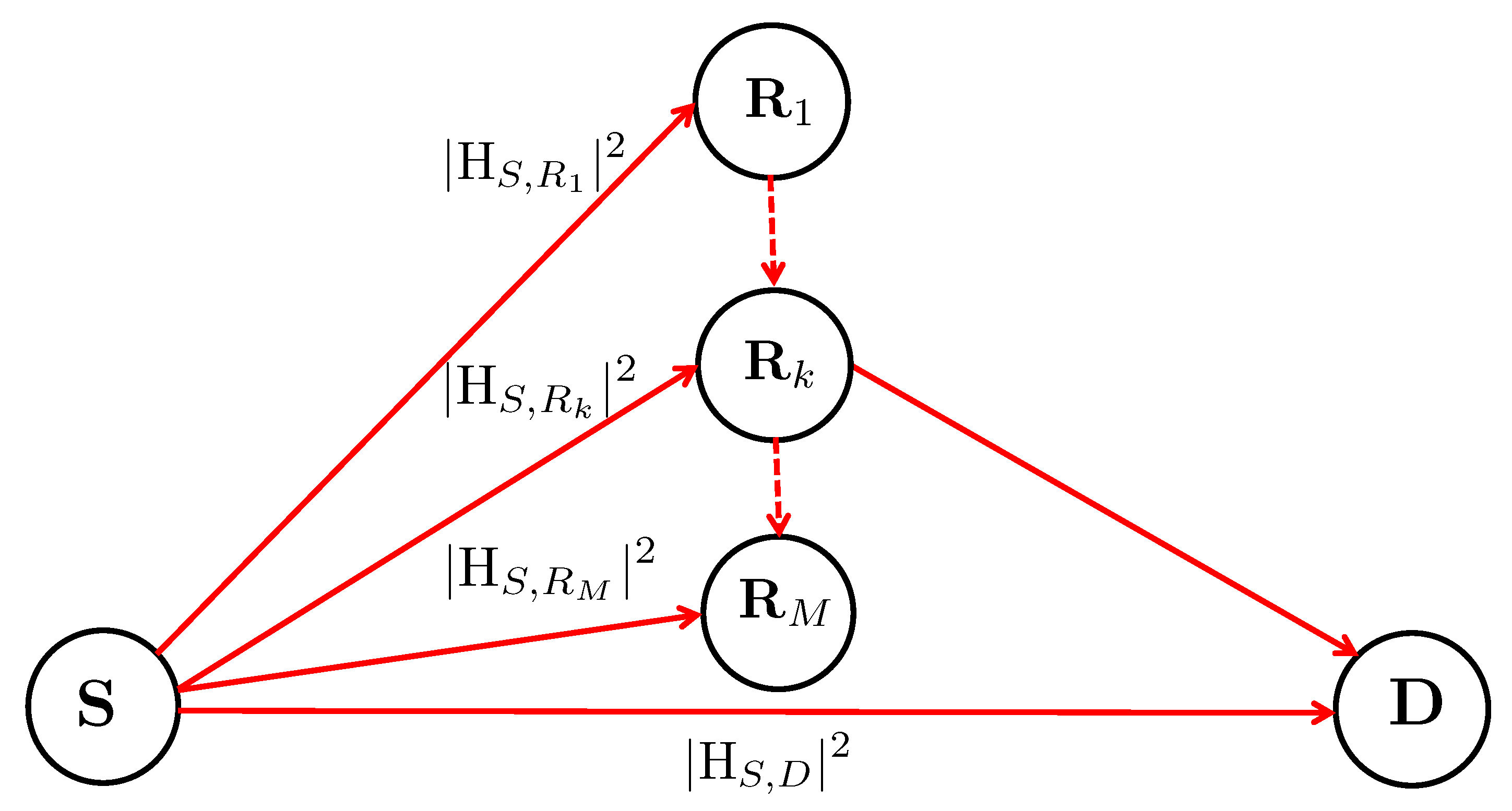
As shown in Figure 2, the network is made up of source node S, destination node D, and M EH relay nodes R k , k { 1 , 2 , , M } . Network devices are limited to just one antenna and are assumed to be half-duplex. This configuration is commonly found in low-cost sensor networks [25]. We assume that when the source broadcasts its message, all network nodes, including the destination, attempt to decode it. The relays that successfully decode the message during the first phase create a decoding set, indicated as D , which includes all of the relay nodes R k that successfully decoded the message. When the destination can not decode the information successfully in the first phase, it broadcasts a NACK to initiate the contention process at the beginning of the second phase. During this second phase, all the relay nodes in the decoding set D actively participate. The best relay among them is selected during the subsequent ACK process by the relays, which will transmit the decoded information in return for the energy received from either source or destination, i.e., SWPT or DWPT. The details of SWPT and DWPT are described in Section 3. We assume that the EH relays are equipped with an adaptive power splitting (APS) receiver [26], which enables them to efficiently perform simultaneous energy harvesting and information decoding from the received signal. The main purpose of employing the APS protocol is that the PS ratio is adaptive and need not be optimized as conventional PS protocol. The details of the APS protocol are covered in the subsequent section, and the symbols and their corresponding abbreviation are given in Section Abbreviation.

2.2. Channel Model

In order to streamline our subsequent analyses, we simplify the connections between the nodes by assuming that the signal strength remains constant throughout a time slot but may vary from one slot to another. Considering a connection experiencing Rayleigh fading, the channel gain is represented by h u , v R , where u { S , R k } and v { R k , D } . The probability density function (pdf) of h u , v is [27]
p h u , v ( x ) = 1 λ u , v exp x λ u , v
where λ u , v = E ( h u , v ) , with E ( · ) representing an expectation operation.
Let us assume w v denotes the additive white Gaussian noise (AWGN) at the vth relay node with variance σ v 2 , where v { R k , D } . Additionally, we consider that all the relay nodes in the network have the same noise level, i.e., σ R k 2 = σ R 2 for any k { 1 , , M } . For the sake of simplicity, we denote the channel gains related to fading between the various nodes, shown in Figure 2, as f | H S , D | 2 , g k | H S , R k | 2 , and h k | H R k , D | 2 . Let us assume the separation between S and D, S and R k , and R k and D is denoted by d S , D , d S , R k , and d R k , D , respectively. We then assume that d S , D = d 0 , d S , R k = d 1 , and d R k , D = d 2 for all k. Usually, clustering algorithms are utilized to group relay nodes together into clusters based on their geographical proximity. Additionally, we assume R k and D lie roughly along the same path from S. This translates to an approximate relationship between the distances such that d S , D d S , R k + d R k , D or in other words d 0 d 1 + d 2 . Note that these assumptions are only for simplicity and do not play an essential part in our subsequent analysis and results.

2.3. SWIPT Receiver

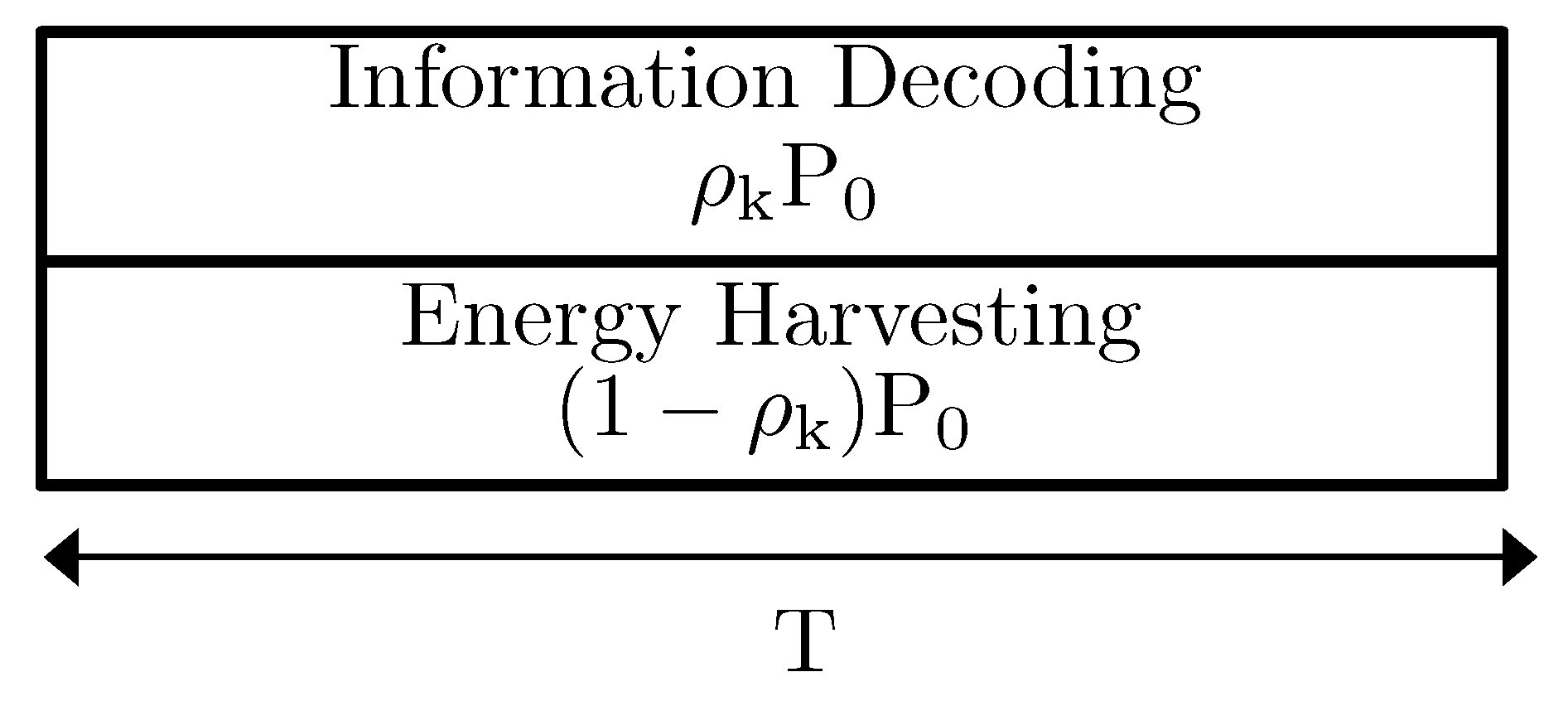
The adaptive power splitting (APS) protocol that is adopted for our SWIPT receiver is presented in Figure 3, where the incoming data stream is dynamically divided into two branches. A power-splitting ratio, denoted by ρ k (ranging from 0 to 1), determines the allocation of received signal power P between these branches. Specifically, ρ k P is allocated for ID, while the remaining portion, ( 1 ρ k ) P , is used for EH, as described in previous works [28,29]. The term adaptive is used for this protocol because the value of ρ k is determined dynamically based on the channel gain at each relay. This adaptation ensures that only the minimum required signal power is directed to the information decoding (ID) unit, while the remaining power is harvested by the EH unit. We assume that all the energy harvested in this phase will be used by the relay node to broadcast the ACK signal.
The achievable data rate for communication between S and receiver R k under the APS protocol can be described mathematically as
C S , R k = log 2 1 + ρ k P 0 g k σ R 2 d 1 m
in the above equation, P 0 represents the average power of the signal sent by the source node; T, on the other hand, signifies the total time allocated for data transmission across the entire link, encompassing the transmission from the transmitter to the receiver. Additionally, ρ k ( 0 , 1 ) denotes the PS ratio, m stands for the path loss exponent, and d 1 refers to the distance between the source and the relay cluster. For the desired data transmission rate R , a specific power allocation ratio ρ k is necessary for the relay to reliably detect the signal, which can be stated as follows.
ρ k = min 1 , 2 R 1 g k γ k
where
γ k = P 0 σ R 2 d 1 m .
With a designated power allocation ratio ρ k , the amount of energy captured by the kth relay can be determined as
E k = ζ ( 1 ρ k ) g k η P 0 d 1 m
where ζ ( 0 , 1 ] represent the conversion efficiency.
From (3), it can be observed that in the APS protocol, the relay can dynamically calibrate the PS ratio ρ k by leveraging the instantaneous channel state information (CSI). In the DF relaying, where the relay needs to successfully decode the received signal before it can take part in relaying, APS is the best approach as compared to the PS approach, where the PS ratio is predefined [26]. If we assume that the least energy required to broadcast the ACK signal by the relay node is E A , the minimum signal strength required to collect E A , the amount of energy, can be expressed as
Γ A = 2 R 1 σ R 2 d 1 m P 0 + E A d 1 m ζ η P 0
This formula can be broken down into two key components. The first part reflects the minimum signal strength necessary for the successful retrieval of the received information. The other part accounts for the signal strength needed to capture E A unit of energy. In our system model, the relay nodes can successfully decode the signal as well as harvest E A from the decoding set D . From (6), the probability that exactly n nodes are in the decoding set is given by the binomial distribution as [30]
p n P D = n = M n 1 F g ( Γ A ) n F g M n ( Γ A )
where
F g ( x ) = 1 exp x λ g
represent the cumulative distribution function (CDF) of random variable g with parameter λ g , | · | denotes the cardinality of the set, and M n = M ! ( M n ) ! n ! .

3. Performance Analysis

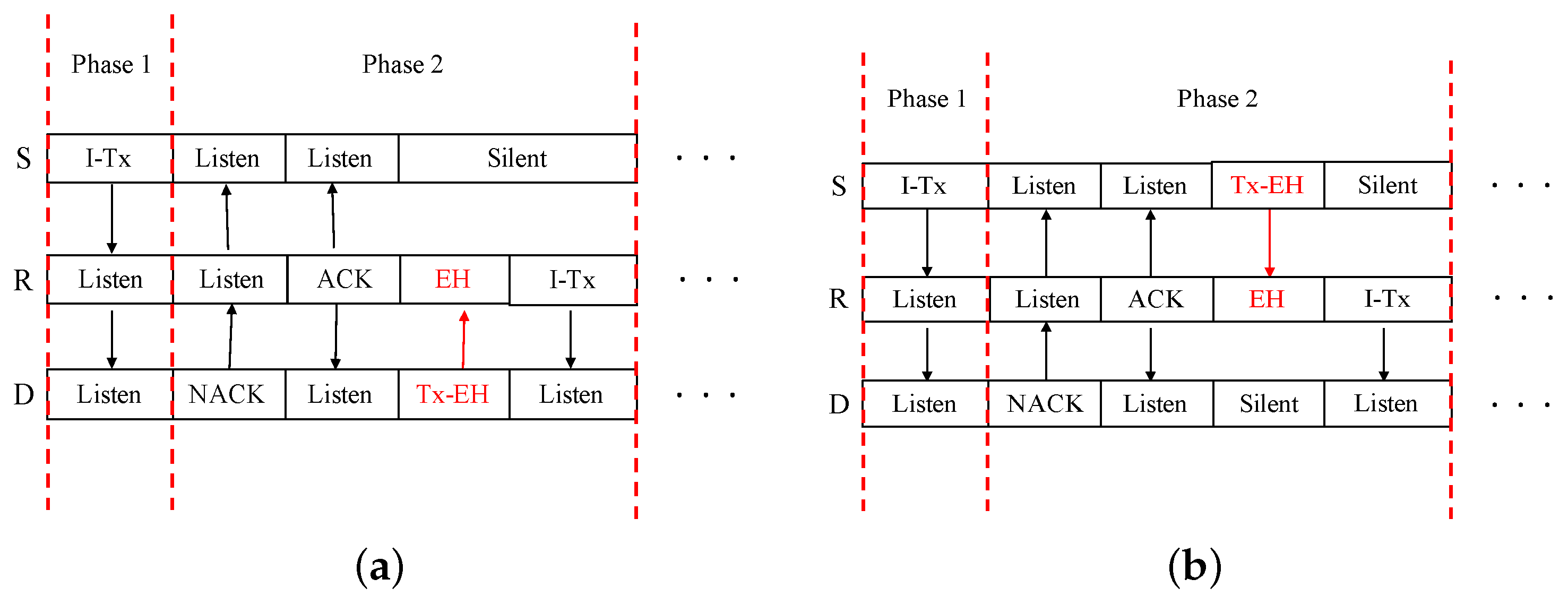
As shown in Figure 4, our procedure is divided into two distinct phases: Phase 1 and Phase 2. In Phase 1, the source broadcasts the information to all nodes. In Phase 2, if the destination fails to decode the information, it requests assistance from relay nodes by broadcasting the NACK signal. Based on the instantaneous channel gain, one of the relays is selected to re-transmit the decoded signal. The relay selection approach is explained in detail in the subsequent analysis. The energy required for this re-transmission is either provided by the destination, as shown in Figure 4a, or by source, as depicted in Figure 4b.
During Phase 1, the source disseminates the information, and all other nodes in the network attempt to decode it. The channel capacity at the destination can be expressed as follows:
C S , D = log 2 1 + P 0 f σ D 2 d 0 m
where f = | H S , D | 2 , and d 0 is the distance between S and D. From (9), the SNR required to decode the received signal can be represented as
Γ S D = ( 2 R 1 ) d 0 m σ D 2 P 0 .
In the first phase, when the destination fails to decode the message in the direct link between S and D it is said to be in outage, and its probability can be written as
P out = P f Γ S D = 1 exp ( λ f Γ S D ) .
As shown in Figure 4, when the direct link is in an outage, the protocol enters into the second phase, where the destination first broadcasts the NACK signal. The successful relays R k D then enters into contention. There are various ways to resolve the contention, and in this work we consider the timer-based algorithm proposed in [31], where as soon as the relay obtains the NACK from the destination, they set their respective timer with the following waiting time
T k = Δ h k
with Δ denoting a suitable time unit [31].
The relay with minimum waiting first signals its availability, prompting all other relays to withdraw their attempts to claim the task. As a result, the relay with the shortest waiting time, i.e., the relay with the best relay-to-destination connection, will be chosen to broadcast a 1-bit ACK signal. Note that if none of the relays broadcast ACK signals within the predetermined maximum time period, the source and destination would assume that the decoding set is empty. In such a case, the source should re-transmit the information. Additionally, all the energy harvested in the first phase, i.e., (5), will be utilized for the ACK broadcasting.

3.1. DWPT Schemes

In the DWPT scheme described in Figure 4a, in Phase 2, once the relay broadcasts the ACK signal with the other relays taking back off, the destination reciprocates with the energy signal. Let k denote the index of the selected relay R k . The relay R k then harvests energy through the signal, which can be expressed as
E k = ζ d 2 m h k P D T 0
where d 2 is the distance between R k (for any k) and D, T 0 is the time unit for energy harvesting, and P D is the power transmitted by the destination. Because the relay will use 100% of the gathered energy for data transmission, the mathematical representation of the chosen relay node’s transmission power may be expressed as
P r = E k T 0 = ζ d 2 m h k P D .
The mutual information for the link from the relay to the destination can be expressed as
C R k , D = 1 2 log 2 1 + P r h k d 2 m σ D 2 = 1 2 log 2 1 + ζ h k 2 P D d 2 2 m σ D 2
where σ D 2 is the AWGN at the destination. The channel gain h k 2 needed for reliable decoding of the received signal at the destination could be represented as
Γ R D = ( 2 2 R 1 ) d 2 2 m σ D 2 ζ P D .
In the D-WPT scheme, the system is said to be in outage if (i) all the links S D and S R k are in outage, or (ii) the links S D and R k D are in outage while at least one of the links S R k is not. The resulting outage probability can be expressed as
P out D E = P { ( f < Γ S D D = 0 ) ( f < Γ S D D 1 h k 2 < Γ R D ) }
with f = | H S , D | 2 and h k = | H R k , D | 2 , where Γ S D and Γ R D are derived in (10) and (16), respectively. Since all the links are independent, the above equation can be written as
P out D E = P { f < Γ S D } P { D = 0 } + P h k < Γ R D ( | D | 1 )
= F f ( Γ S D ) p 0 + n = 1 N p n F h n ( Γ R D )
where p n is defined in (7) and
F h ( x ) = 1 exp x λ h
is the CDF of the exponential random variable h with parameter λ h .

3.2. S-WPT Scheme

If the relay is closer to the source, the S-WPT could be a good choice. As shown in Figure 4b, it is the same as that of the D-WPT scheme except for the energy cooperation subplot, where the source rather than the destination helps relay. As a consequence, the relay selection criteria should be modified accordingly. For example, the waiting time for the S-WPT scheme should be expressed as
T k = Δ g k
where g k = | H S , R k | 2 . The energy harvested by the selected relay can be expressed as
E k = ζ d 1 m g k P 0 T 0
where d 1 is the distance between the source and relay, and P 0 is the power transmitted by the source node. The power at the selected relay can be calculated as
P r = E k T 0 = ζ d 1 m g k P 0 .
Maximum achievable data transmission rate at the destination can be written as
C R k , D = 1 2 log 2 1 + P r h k d 2 m σ D 2 = 1 2 log 2 1 + ζ g k h k P 0 d 1 m d 2 m σ D 2 .
The SNR required to reliably decode the signal at the destination could be formulated as
Γ R D = ( 2 2 R 1 ) d 1 m d 2 m σ D 2 ζ P 0 .
For a given Γ R D and the decoding set D , the probability of an outage can be written as
P out R D = P h k × max j D g j < Γ R D ,
when D = n , the above probability can be expressed as
P out R D = 0 F g n ( Γ R D / h k ) 1 F h ( h k ) d h k = 0 1 exp ( Γ R D / h k ) n exp ( h k ) d h k
with the help of the binomial series, the above equation can be formulated as
P out R D = = 0 n ( 1 ) n n 0 exp ( Γ R D / h k ) exp ( h k ) d h k
where ( 1 x ) n = = 0 n n ( 1 ) n x , the above equation can be expressed as
P out R D = 2 = 0 n ( 1 ) n n Γ R D K 1 2 Γ R D
where K 1 is the second kind of modified Bessel function. In the S-WPT scheme, the system is said to be in outage if (i) both links between S R k and S D are in outage, or (ii) the links R k D and S D are in outage whereas S R k is not. The probability of an outage can be calculated as
P out S E = P ( f < Γ S D ) D = 0 ( f < Γ S D ) ( D 1 ) ( g k h k < Γ R D )
which can be written as
P out S E = P { f < Γ S D } P { D = 0 } + P ( g k h k < Γ R D ) ( D 1 ) .
By using (7), (11), and (29), the probability of an outage can be formulated as
P out S E = F f ( Γ S D ) p 0 + 2 n = 1 M p n = 0 n ( 1 ) n n Γ R D K 1 2 Γ R D .

3.3. Hybrid Scheme

For each of D-WPT and S-WPT schemes, the energy sources are fixed and thus may not be necessarily optimal for a given channel realization. In order to overcome this, we propose a hybrid scheme, where they can select the best energy source for a given channel condition. The process of the hybrid scheme is the same as that of the D-WPT scheme, except for that in the proposed scheme, the relay node compares the instantaneous channel gain h k with the threshold Γ R D , which is given in (16). If the channel gain is greater than the required threshold, it will broadcast 1 and otherwise, it will broadcast 0. When the ACK signal is 1, the destination will provide energy to R k , i.e., it becomes D-WPT, and otherwise the source provides the energy, i.e., it becomes S-WPT. Otherwise,
ACK = 1 , i f h k Γ R D 0 , otherwise
where h k = max k D h k . The outage probability for the hybrid scheme can be expressed as
P out H Y = P out D E P out S E
where P out D E and P out S E are given in (18) and (32), respectively.

4. Numerical Results and Discussion

Building on the theoretical groundwork from previous sections, this section presents various numerical results and their interpretations. In this research work, the outage probability is the performance metric. The reliability of the analytic results derived in the previous section are corroborated with the help of simulation results obtained through Monte-Carlo simulations. The variables defined in Table 1 are considered for obtaining the simulation result. Further relevant variables will be introduced as required.

4.1. Analytical and Numerical Analysis

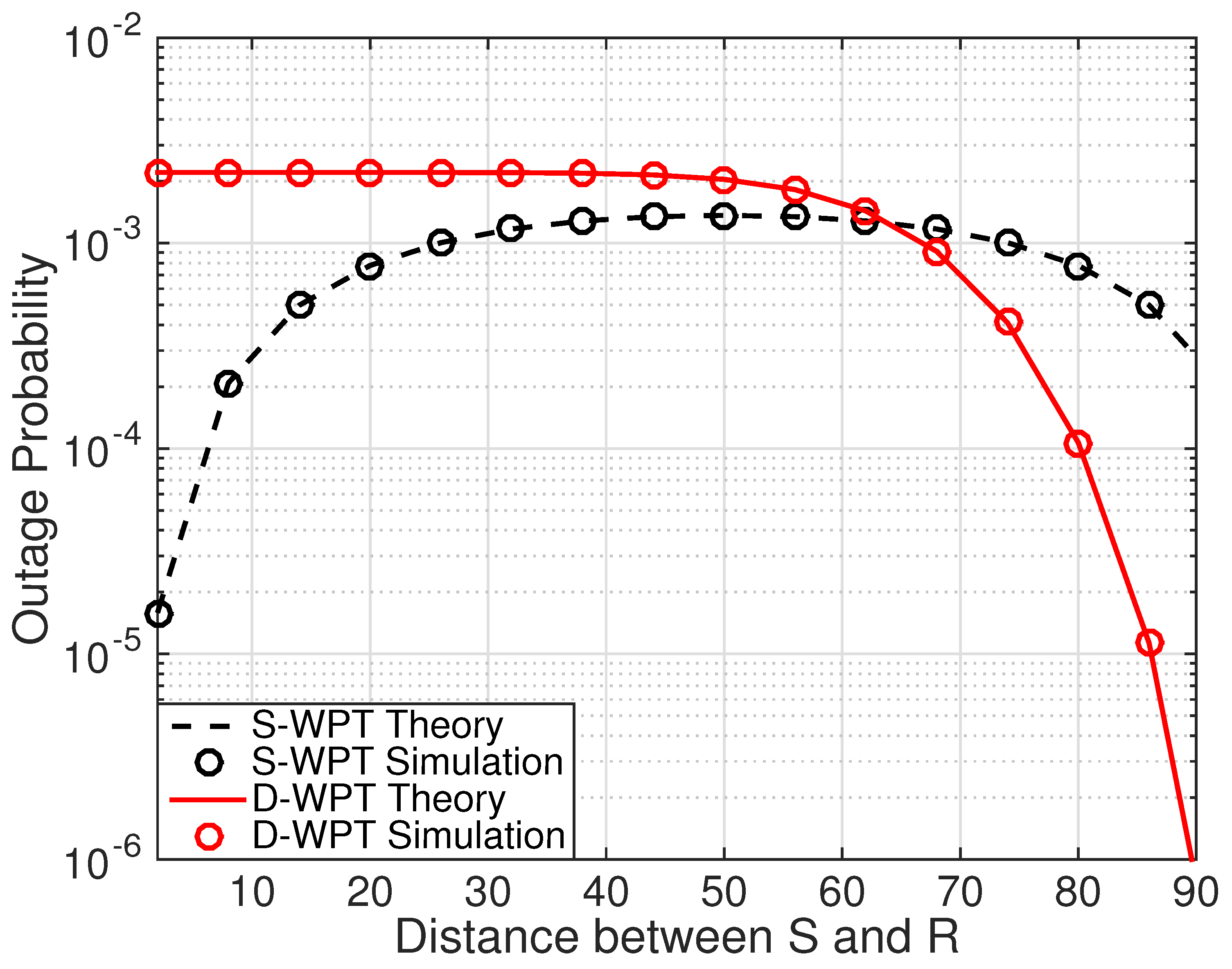
This subsection verifies and examines the analytical results obtained in the preceding sections for different schemes through simulation results. All simulation results are averaged over 10 7 channel realizations. Figure 5 presents a comparison of outage probabilities between theoretical predictions (lines) and simulation results (circular marks) for a Rayleigh fading channel.
The close agreement between theoretical and simulation results demonstrates the precision of our theoretical analysis. This concurrence confirms that our analytical models effectively represent the system’s behavior across different channel conditions and relay distances. By examining the impact of d 1 , we gain insights into how relay positioning affects outage probability, which can inform strategies for optimal relay placement to minimize outages. This comparison not only verifies the robustness of our theoretical models but also offers practical recommendations for system design in real-world applications.

4.2. Comparison with Hybrid Approach

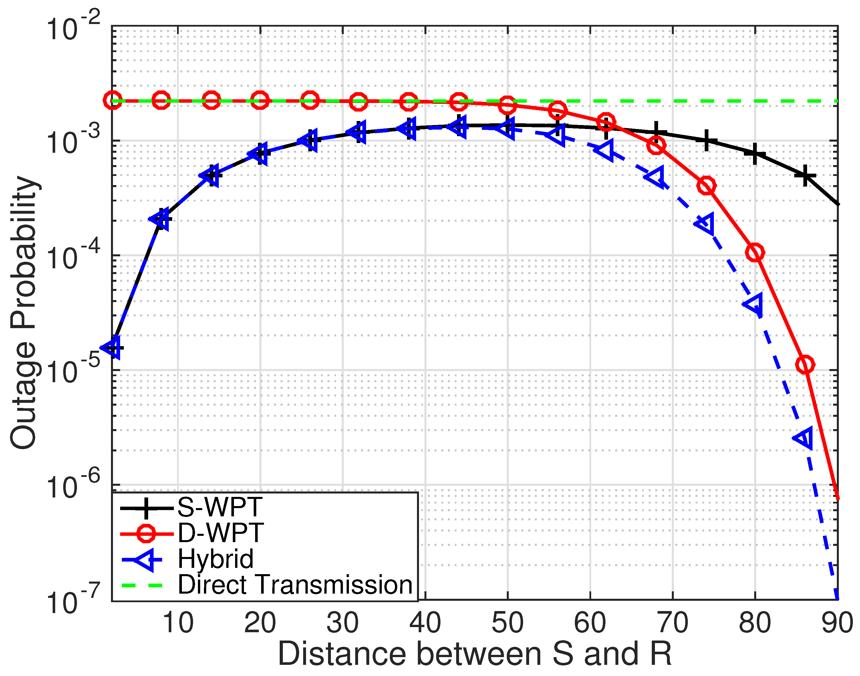
Figure 6 shows the outage performance of various WPT schemes. From the result, it can be observed that when the relay is closer to the source, the S-WPT scheme outperforms the D-WPT scheme, and vice versa is true when the relay is closer to the destination.
This can be explained by the differences in signal strength and path loss. A relay closer to the source benefits from a stronger initial signal, while a relay near the destination experiences reduced path loss during the second transmission hop.
Regarding the hybrid scheme, it mimics the S-WPT scheme’s performance when the relay is closer to the source due to the strong initial signal. However, as the relay moves closer to the destination and the outage probability of the S-WPT scheme intersects with that of the D-WPT scheme, the hybrid scheme begins to outperform both. This crossover highlights the hybrid scheme’s capability to switch adaptively between the strengths of both S-WPT and D-WPT schemes, thereby optimizing performance under varying conditions.
Importantly, the proposed hybrid scheme does not increase system complexity or signaling overhead. This is a crucial advantage, as it means the enhanced performance is achieved without additional resource usage or implementation difficulties. The scheme’s ability to efficiently manage energy transfer and maintain reliable communication links without added complexity underscores its practicality for real-world applications, where low complexity and minimal overhead are vital.
Additionally, the hybrid scheme’s adaptability ensures it can sustain optimal performance across different relay positions and network conditions. This versatility makes it suitable for a wide range of deployment scenarios, enhancing its potential for diverse wireless power transfer applications.

4.3. Effect of Relay Nodes

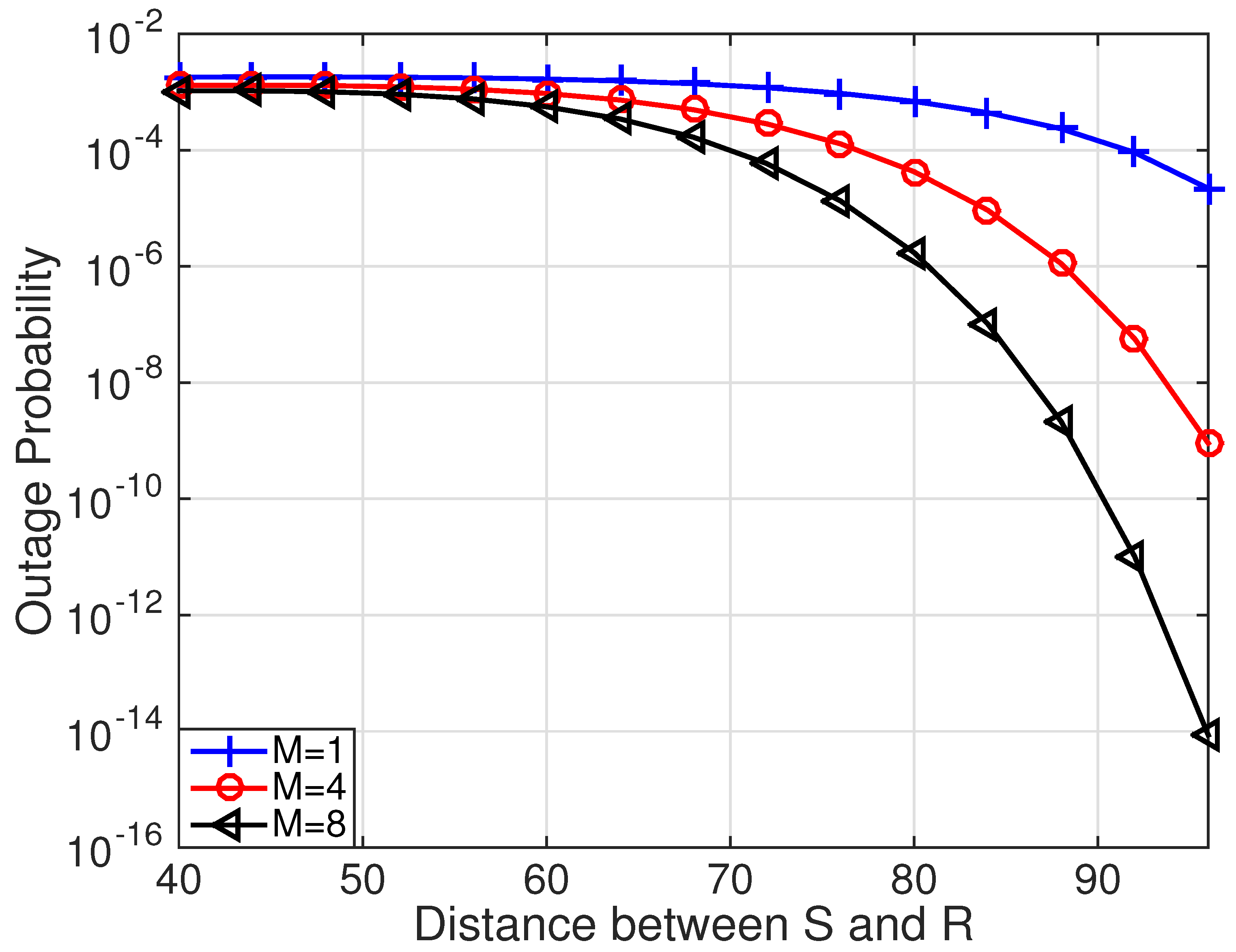
From this subsection onward, the hybrid schemes will be used for our numerical analysis. The relationship between d 1 and outage probability for various cases of relay nodes (M) is shown in Figure 7. The results indicate a positive correlation between the number of relay nodes and network performance. Specifically, we observe an enhancement in outage performance as the number of relay nodes increases.
This improvement can be attributed to the additional diversity and signal paths provided by multiple relay nodes, which help to counteract fading effects and reduce outage probability. The presence of more relay nodes introduces redundancy, creating multiple pathways for the signal and thereby enhancing the reliability and robustness of the communication link. This redundancy allows the network to better handle channel impairments, ensuring a more stable and consistent connection.
The data clearly show that with an increase in M, the network becomes more adept at managing adverse conditions, significantly lowering the outage probability. These findings highlight the crucial role of relay nodes in boosting network resilience and performance, especially in challenging environments. By utilizing multiple relay nodes, the hybrid scheme maximizes the chances of successful data transmission, demonstrating its effectiveness and practicality in real-world wireless communication scenarios.

4.4. Effect of Power Consumed by Relay to Broadcast ACK

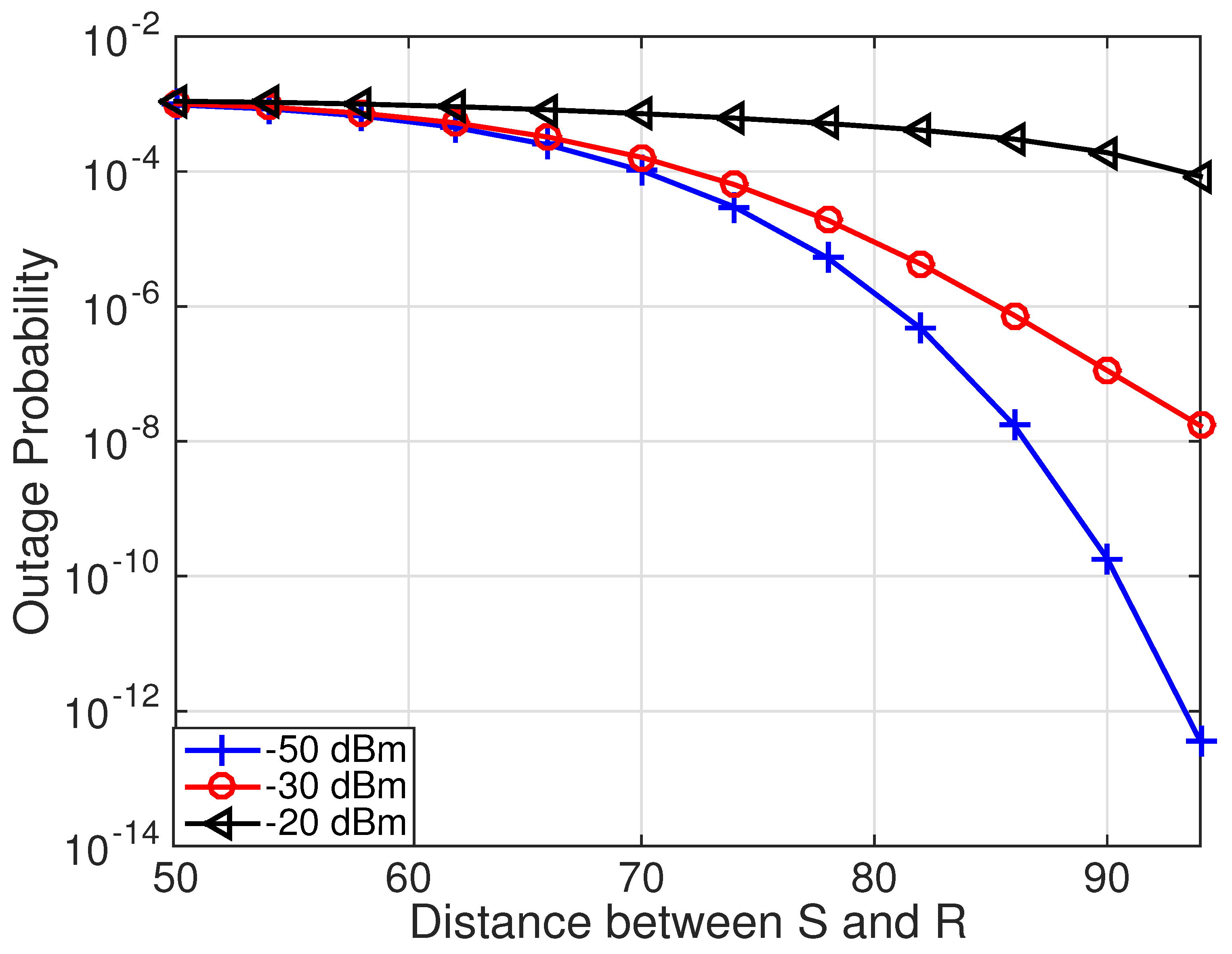
Finally, the relationship between the outage probability for various P A and d 1 is shown in Figure 8. From the results, it can be observed that the performance of the energy harvesting relaying network is greatly affected by the amount of power used by the relay node to broadcast the ACK signal. In this work, we have assumed that the relay utilizes the energy harvested in the first phase for the signaling purpose.
Furthermore, it is possible for the energy needed for signaling to be obtained from the NACK signal transmitted by the destination. This suggests that even if ACK signaling encounters constraints, the network can maintain its performance through the strategic use of NACK signals. This adaptability in sourcing energy for signaling ensures that the relay node continues to function effectively, thereby sustaining network performance under different energy conditions. Our results underscore the critical role of efficient energy management in energy harvesting relay networks.

5. Conclusions

This study presents a novel H-WPT scheme for IIoT networks with multiple relay nodes, enabling relay nodes to dynamically select their power source for energy harvesting based on real-time channel conditions. The scheme operates in a decentralized manner, allowing relay nodes to independently select the optimal relay and power source using instantaneous channel gain. This decentralized approach conserves energy that would otherwise be expended in centralized control, which involves extensive information exchange between nodes. This energy conservation is vital in energy-constrained sensor networks as it significantly extends the network’s operational lifetime. Numerical results show that the proposed hybrid approach outperforms individual D-WPT and S-WPT methods. This performance improvement is achieved without additional energy consumption or increased system complexity, making it an attractive solution for energy-harvesting cooperative relaying networks. The efficient power management and decentralized operation of the scheme highlight its potential for practical applications in IIoT environments, where optimizing resources is essential.

Author Contributions

Conceptualization, V.S.; methodology, V.S.; validation, V.S., R.K., B.M. and C.R.S.; formal analysis, V.S., R.K., B.M. and C.R.S.; investigation V.S., R.K., B.M. and C.R.S.; writing—original draft preparation V.S.; writing—review and editing R.K., B.M. and C.R.S. All authors have read and agreed to the published version of the manuscript.

Funding

The APC was funded by Manipal Academic of Higher Education, Manipal 576104, Karnataka, India.

Data Availability Statement

Data are contained within the article.

Conflicts of Interest

The authors declare no conflicts of interest.

Abbreviations

SymbolsDefinition
S and DSource and destination nodes
R k Relay node
h u , v Channel gain between S and D
w v Additive white Gaussian noise
PReceived signal power over a channel
P 0 Average signal power sent by a transmitting node over a time period T
σ R k 2 Noise level over a channel
ρ k P Power-splitting ratio
C S , R k Achievable data rate between S and R k
Γ A Minimum signal strength required to collect energy over a split channel
γ k Signal to noise ratio over a split channel
g k Gain of the channel
mPath loss exponent
ζ Conversion efficiency
T k Waiting time required by R k to receive an ACK or NACK message

References

  1. Chi, H.R.; Wu, C.K.; Huang, N.F.; Tsang, K.F.; Radwan, A. A Survey of Network Automation for Industrial Internet-of-Things Toward Industry 5.0. IEEE Trans. Ind. Inform. 2023, 19, 2065–2077. [Google Scholar] [CrossRef]
  2. Chen, Y.; Lyu, B.; Yang, Z.; Li, F. Wireless-Powered Relays Assisted Batteryless IoT Networks Empowered by Energy Beamforming. Inst. Electron. Inf. Commun. Eng. 2023, 106, 164–168. [Google Scholar] [CrossRef]
  3. Varshney, L.R. Transporting information and energy simultaneously. In Proceedings of the IEEE International Symposium on Information Theory, Toronto, ON, Canada, 6–11 July 2008; pp. 1612–1616. [Google Scholar]
  4. Grover, P.; Sahai, A. Shannon meets tesla: Wireless information and power transfer. In Proceedings of the IEEE International Symposium on Information Theory, Austin, TX, USA, 13–18 June 2010; pp. 2363–2367. [Google Scholar] [CrossRef]
  5. Fouladgar, A.M.; Simeone, O. On the transfer of information and energy in multi-user systems. IEEE Commun. Lett. 2012, 16, 1733–1736. [Google Scholar] [CrossRef]
  6. Choi, K.W.; Hwang, S.I.; Aziz, A.A.; Jang, H.H.; Kim, J.S.; Kang, D.S.; Kim, D.I. Simultaneous wireless information and power transfer (SWIPT) for Internet of Things: Novel receiver design and experimental validation. IEEE Internet Things J. 2020, 7, 2996–3012. [Google Scholar] [CrossRef]
  7. Liu, L.; Zhang, R.; Chua, K.C. Wireless Information Transfer with Opportunistic Energy Harvesting. IEEE Trans. Wirel. Commun. 2013, 12, 288–300. [Google Scholar] [CrossRef]
  8. Zhang, R.; Ho, C.K. MIMO Broadcasting for Simultaneous Wireless Information and Power Transfer. IEEE Trans. Wirel. Commun. 2013, 12, 1989–2001. [Google Scholar] [CrossRef]
  9. Nasir, A.A.; Zhou, X.; Durrani, S.; Kennedy, R.A. Relaying Protocols for Wireless Energy-Harvesting and Information Processing. IEEE Trans. Inf. Theory 2013, 12, 3622–3636. [Google Scholar] [CrossRef]
  10. Nasir, A.A.; Zhou, X.; Durrani, S.; Kennedy, R.A. Throughput and ergodic capacity of wireless energy harvesting based DF relaying network. In Proceedings of the 2014 IEEE International Conference on Communications, ICC 2014, Sydney, Australia, 10–14 June 2014; pp. 4066–4071. [Google Scholar] [CrossRef]
  11. Gu, Y.; Sonia, A. Interference Aided Energy Harvesting in Decode-and-Forward Relaying Systems. In Proceedings of the 2014 IEEE International Conference on Communications (ICC), Sydney, Australia, 10–14 June 2014; pp. 5389–5393. [Google Scholar]
  12. Gu, Y.; Sonia, A.; Aïssa, S. RF-Based Energy Harvesting in Decode-and-Forward Relaying Systems: Ergodic and Outage Capacities. IEEE Trans. Wirel. Commun. 2015, 14, 6425–6434. [Google Scholar] [CrossRef]
  13. Liu, Y. Wireless Information and Power Transfer for Multirelay-Assisted Cooperative Communication. IEEE Commun. Lett. 2016, 20, 784–787. [Google Scholar] [CrossRef]
  14. Do, N.T.; Bao, V.N.Q.; An, B. Outage Performance Analysis of Relay Selection Schemes in Wireless Energy Harvesting Cooperative Networks over Non-Identical Rayleigh Fading Channels. Sensors 2016, 16, 295. [Google Scholar] [CrossRef]
  15. Mao, M.; Cao, N.; Chen, Y.; Zhou, Y. Multi-Hop Relaying Using Energy Harvesting. IEEE Wirel. Commun. Lett. 2015, 4, 565–568. [Google Scholar] [CrossRef]
  16. Singh, V.; Ochiai, H. Performance analysis of the clustering-based multihop wireless energy harvesting sensor networks over symmetric and asymmetric fading channels. Int. J. Distrib. Sens. Netw. 2017, 13, 12. [Google Scholar] [CrossRef]
  17. Do, D.T. Optimal Throughput under Time Power Switching Based Relaying Protocol in Energy Harvesting Cooperative Networks. Mobile Inf. Syst. 2015, 2015, 8. [Google Scholar] [CrossRef]
  18. Atapattu, S.; Evans, J. Optimal energy harvesting protocols for wireless relay networks. IEEE Trans. Wirel. Commun. 2016, 15, 5789–5803. [Google Scholar] [CrossRef]
  19. Tao, R.; Salem, A.; Hamdi, K. Adaptive Relaying Protocol for Wireless Power Transfer and Information Processing. IEEE Commun. Lett. 2016, 20, 2027–2030. [Google Scholar] [CrossRef]
  20. Huang, Y.; Clerckx, B. Joint Wireless Information and Power Transfer for an Autonomous Multiple Antenna Relay System. IEEE Commun. Lett. 2015, 19, 1113–1116. [Google Scholar] [CrossRef]
  21. Zhang, C.; Chen, Y. Wireless Power Transfer Strategies for Cooperative Relay System to Maximize Information Throughput. IEEE Access 2017, 5, 2573–2582. [Google Scholar] [CrossRef]
  22. Lyu, B.; Hoang, D.T. Optimal time scheduling in relay assisted batteryless IoT networks. IEEE Wirel. Commun. Lett. 2020, 9, 706–710. [Google Scholar] [CrossRef]
  23. Jung, H.; Lee, B. Wireless Power and Bidirectional Data Transfer System for IoT and Mobile Devices. IEEE Trans. Ind. Electron. 2022, 69, 11832–11836. [Google Scholar] [CrossRef]
  24. Liu, Y.; Wang, L.; Elkashlan, M.; Duong, T.Q.; Nallanathan, A. Two-way relaying networks with wireless power transfer: Policies design and throughput analysis. In Proceedings of the 2014 IEEE Global Communications Conference, Austin, TX, USA, 8–12 December 2014. [Google Scholar] [CrossRef]
  25. Raghunathan, V.; Ganeriwal, S.; Srivastava, M. Emerging Techniques for Long Lived. IEEE Commun. Mag. 2006, 44, 108–114. [Google Scholar] [CrossRef]
  26. Singh, V.; Ochiai, H. An Efficient Time Switching Protocol with Adaptive Power Splitting for Wireless Energy Harvesting Relay Networks. In Proceedings of the 2017 IEEE 85th Vehicular Technology Conference (VTC Spring), Sydney, Australia, 4–7 June 2017. [Google Scholar] [CrossRef]
  27. Proakis, J.G.; Salehi, M. Digital Communications, 5th ed.; McGrawhill: New York, NY, USA, 2008. [Google Scholar]
  28. Singh, V.; Ochiai, H. Throughput Improvement by Cluster-Based Multihop Wireless Networks with Energy Harvesting Relays. In Proceedings of the IEEE Topical Conference on Wireless Sensors and Sensor Networks (WiSNet), Phoenix, AZ, USA, 15–18 January 2017; pp. 61–64. [Google Scholar]
  29. Ding, Z.; Krikidis, I.; Sharif, B.; Poor, H.V. Wireless information and power transfer in cooperative networks with spatially random relays. IEEE Trans. Wirel. Commun. 2014, 13, 4440–4453. [Google Scholar] [CrossRef]
  30. Tannious, R.; Nosratinia, A. Spectrally-efficient relay selection with limited feedback. IEEE J. Sel. Areas Commun. 2008, 26, 1419–1428. [Google Scholar] [CrossRef]
  31. Bletsas, A.; Khisti, A.; Reed, D.P.; Lippman, A. A Simple Cooperative Diversity Method Based on Network Path Selection. IEEE J. Sel. Areas Commun. 2006, 24, 659–672. [Google Scholar] [CrossRef]
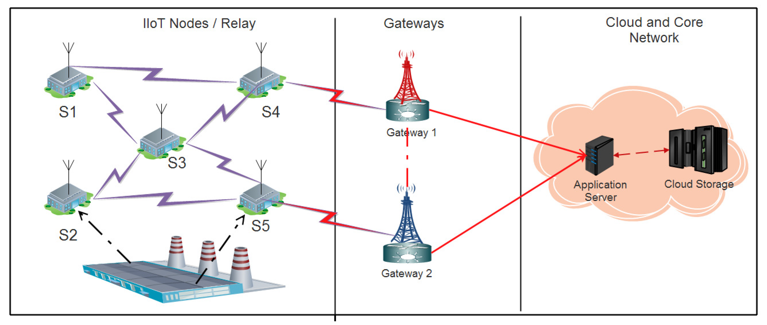
Figure 1. A relay network model.
Designs 08 00084 g001
Figure 2. A relay network with one source, destination pair, and multiple relay nodes.
Designs 08 00084 g002
Figure 3. Adaptive power splitting protocol.
Designs 08 00084 g003
Figure 4. A caption describing the overall figure. (a) Destination-based wireless power transfer scheme (DWPT). (b) Source-based wireless power transfer scheme (SWPT).
Designs 08 00084 g004
Figure 5. Outage probability versus the d 1 . Parameters: R = 3 , ζ = 0.8 , σ D 2 = 70 dBm, P A = 50 dBm, M = 4 , and P 0 = 3 dBm.
Designs 08 00084 g005
Figure 6. Outage probability versus d 1 . Parameters: R = 3 , ζ = 0.8 , σ D 2 = 70 dBm, P A = 50 dBm, M = 4 , and P 0 = 5 dBm.
Designs 08 00084 g006
Figure 7. Outage probability versus d 1 . Parameters: R = 3 , ζ = 0.8 , σ D 2 = 70 dBm, P A = 50 dBm, and P 0 = 5 dBm.
Designs 08 00084 g007
Figure 8. Outage probability versus d 1 . Parameters: R = 3 , ζ = 0.8 , σ D 2 = 70 dBm, M = 8 , and P 0 = 5 dBm.
Designs 08 00084 g008
Table 1. Simulation variables.
VariablesNumerical Value
Relay node count M = { 4 , 8 }
Spatial separation between S D d 0 = 100  m
Distance between R k D d 2 = d 0 d 1
Target transmission rate R = 3 bit per channel use
Propagation factor m = 2
Power conversion efficiency ζ = 0.8
Source power P 0 = 5  dBm
ACK signaling power of relay P A = 50  dBm
Power of noise σ i 2 = 70  dBm with i { R k , D }
Disclaimer/Publisher’s Note: The statements, opinions and data contained in all publications are solely those of the individual author(s) and contributor(s) and not of MDPI and/or the editor(s). MDPI and/or the editor(s) disclaim responsibility for any injury to people or property resulting from any ideas, methods, instructions or products referred to in the content.