Article

Determination of a High-Power THz Detector for EA-FEL Radiation Using Optical Sampling of GaAs and ZnTe Crystals

1
The Schlesinger Family Center for Compact Accelerators, Ariel University, Ariel 4076414, Israel
2
Department of Electrical Engineering, University of Ariel, Ariel 4076414, Israel
*
Author to whom correspondence should be addressed.
Designs 2022, 6(6), 109; https://doi.org/10.3390/designs6060109
Submission received: 11 September 2022 / Revised: 22 October 2022 / Accepted: 31 October 2022 / Published: 3 November 2022

Abstract

:
This paper presents a diagnostic method for THz pulses produced by EA-FEL. Experimental results present a comparison between ZnTe and GaAs crystals for the detection of a single terahertz pulse using electro-optic sampling. In order to match an electro-optic detector for the EA-FEL radiation, the THz pulse from a source was simultaneously detected by ZnTe and GaAs electro-optic detectors. The GaAs detection system was found to have a shorter response time but low signal-to-noise ratio (SNR) compared to the ZnTe system. The GaAs crystal is suitable for the detection of short THz pulses due to fiber coupling, and the SNR of the GaAs system can be improved using a faster and more sensitive photodetector.

1. Introduction

Millimeter-wave (MMW) and terahertz (THz) radiation, which are situated between the infrared and microwave radiations in the electromagnetic spectrum, can penetrate through dielectric materials, this property can be employed for several important applications [1,2,3,4]. The atmospheric scattering of THz radiation is relatively low compared to that of other radiations [5], and this radiation does not lead to an ionization hazard. Owing to these properties, THz radiation has been utilized in different types of detectors, such as bolometers, electro-optic detectors, and microfabricated antennas on semiconductors. Bolometers have long response times [6], and the development of microfabricated antennas on semiconductors using clean-room facilities requires specific expertise [7]. Although electro-optic detection requires dealing with phase-matching issues, electro-optic sampling is a popular method for terahertz detection due to the free-space electro-optic sampling offering a flat frequency response over an ultra-wide bandwidth and the potential for the simple cross-correlation signal of the terahertz and optical pulses [8,9]. Electro-optic sampling exploits the linear electro-optic effect (Pockels effect), in which an applied electric field induces a refractive index change in non-linear crystals at THz frequencies; this change is proportional to the applied field. The electro-optic Pockels effect in non-linear crystals can be used for electric field sensing via polarisation state modulation techniques. An external electric field results in polarisation rotation of the principal axes of the non-linear crystal that produces a polarization change of a laser beam propagating through the electro-optic crystal [10]. The change in polarization, which is converted into a change in optical power at a polarizer, can then be measured.
P = ( χ 1 + χ 2 E + χ 3 E 2 + . . . ) E
where P is the electric polarization and is proportional to the applied electric field E and χ ( E ) is the electric susceptibility. By expanding χ ( E ) in powers of the field E, the non-linear properties of the crystal can be described [11]. Usually, in the case of EOS, the optical pulse should be shorter than a half-cycle of the THz field to be observed [12,13], in which the electric field to be measured induces a polarization change in the sampling pulse. In this paper, we present the profile of the THz pulse. In this case, a CW laser is used to modulate the optical radiation by the THz wave. Experimental results present a THz detector through the modulation method. As the phase-matching of ZnTe crystals can be performed using 800-nm-wavelength lasers, these crystals have been widely used to detect ultrashort THz pulses using Ti:sapphire fs lasers at a wavelength of approximately 800 nm [14]. Similarly, the phase-matching of GaAs crystals can be performed using 1550-nm-wavelength lasers. The wavelength of 1550 nm is included in the communication range, which means that photodetectors and amplifiers are operational at this wavelength. Researchers have not presented a simultaneous comparison of two systems for single-pulse THz detection in parallel, and there is no reference to the response time and bandwidth of the detection system [14,15]. This paper presents a comparison among electro-optic sampling in ZnTe and GaAs crystals for the detection of a single high-power THz pulse. Experimental results simultaneously compare two different THz pulse detection systems. The comparison refers to the response time and bandwidth of each system, which may facilitate a wide range of future applications of the electro-optic sampling method.
The phase-matching condition of a THz wave is satisfied when the phase velocity of the wave equals the group velocity of the optical pulse [16]. To obtain the phase-matching condition, the Coherence Length, Lc, should be as large as possible [17].
L c = π c ω T H z n o p t i c λ d n o p t i c d λ n T H z
where c is the speed of light, ω T H z is the THz frequency, λ is the optical pulse wavelength, n o p t i c is the optical refractive index, and n T H z is the THz refractive index. Owing to the contribution of low-lying phonon resonances to the THz refractive index, the difference between the optical and THz refractive indices tends to be large in non-linear crystals. The optical refractive indices are obtained by the following equation.
n o p t i c 2 = A + B λ 2 λ 2 D
The values of parameters A, B, and D are listed in Table 1. The group index of the optical pulse with a refractive index n o p t i c is obtained by
n g r o u p = n o p t i c λ d n o p t i c d λ .
To obtain phase-matching conditions, the value of n T H z should be as close as possible to the value of n g r o u p . The selection of an appropriate crystal for the detection depends on the range of THz radiation, as well as on the wavelength of the laser used.

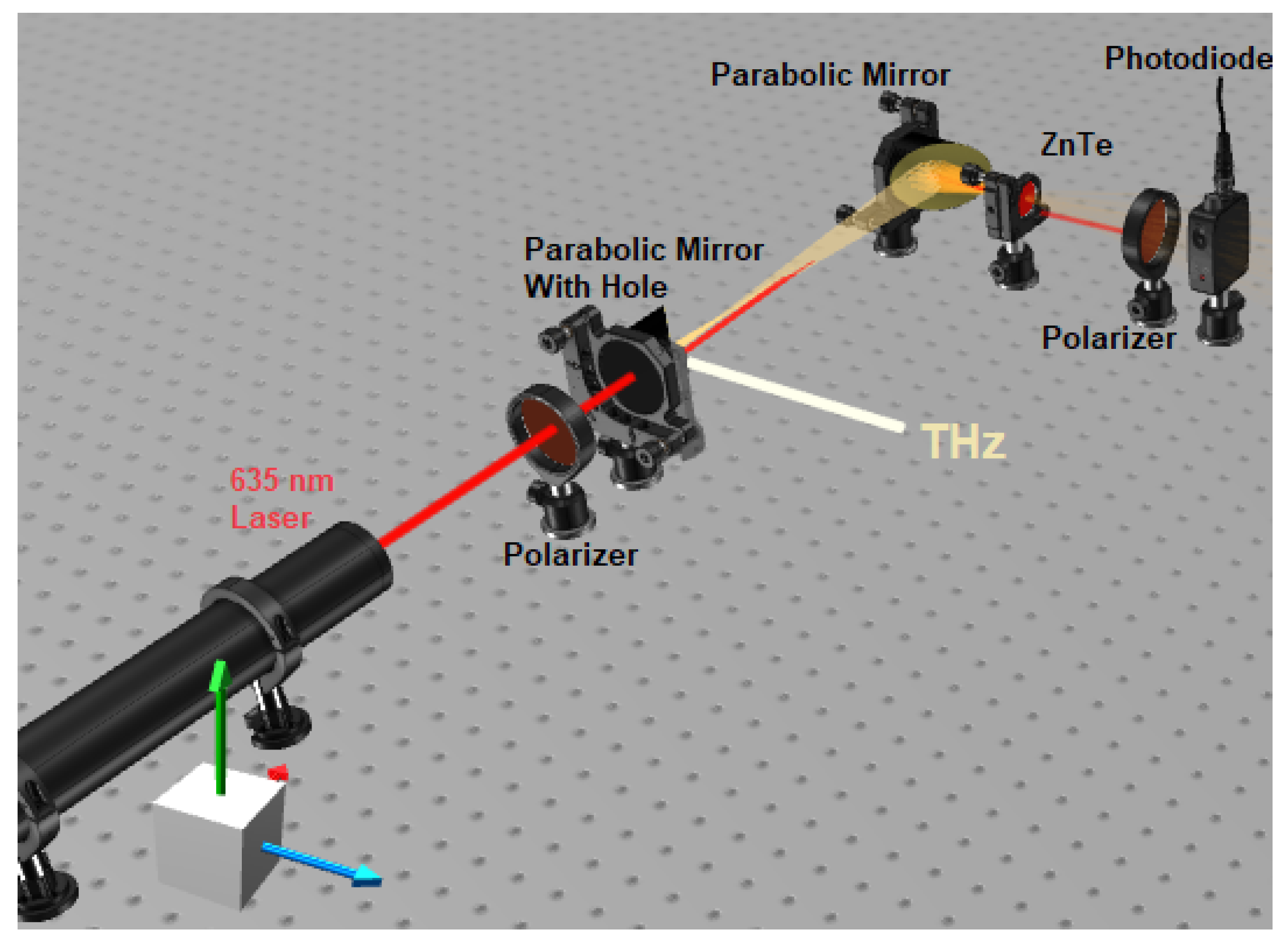
2. Materials and Methods

The MMW accelerator at Ariel University was used as the THz pulse source. The THz pulse had the following parameters: frequency 0.11 THz, width 10 µs, and power 5 kW [19]. A schematic diagram of the electro-optic detection system based on the ZnTe crystal is shown in Figure 1. A continuous wave (CW) laser with a wavelength of 635 nm and power of 200 mW was used as the pump laser. Two off-axis parabolic gold mirrors were used to focus the radiation on the crystal. Two polarizers were used to obtain the cross-polarization condition.
A ZnTe crystal with an orientation of <100> and thickness of 1 mm was used as the electro-optic crystal. A large-area balanced detector (Thorlabs, model PDB210, New Jersey, USA) was used as the photodetector, which was available (the balanced mode was not used). An oscilloscope (Keysight, item DSOX3104A, Hong Kong, China) with a bandwidth of 1 GHz and a maximum sample rate of 5 Gigasamples (GSa)/s was used to analyze the data.
A schematic of the electro-optic detection system using a GaAs crystal is shown in Figure 2. A GaAs crystal with an orientation of <110> and thickness of 1 mm was used as the electro-optic crystal. A CW fiber laser with a wavelength of 1535 nm and power of 40 mW was used as a pump laser. The laser beam was amplified by an erbium-doped fiber amplifier (EDFA) up to 200 mW prior to its incidence on the crystal. The optical signal originating from the GaAs crystal was coupled into the fiber to improve the sampling process, as shown in [20]. As shown in Figure 2, two off-axis gold parabolic mirrors were used to focus the THz pulse onto the GaAs crystal. The cross-polarization condition was obtained by polarizers. A Thorlabs (item DET10C) photodetector was used to detect the optical pulse.

Electrostatic Accelerator Free-Electron Lasers

Electrostatic accelerator free-electron lasers (EA-FEL) can operate in imaging and spectroscopy regimes for scientific and practical applications [21]. Due to the high optical quality of the coherence and power of the radiation beam, the EA-FEL is most fitting for studying THz technologies, especially in spectroscopy. The Israeli EA-FEL, which is based on an electrostatic van de Graaff accelerator, has a highly reliable frequency, radiation values, and output power [19,22]. The main properties of this EA-FEL are summarized in Table 2, while a schematic of the EA-FEL is shown in Figure 3.
The EA-FEL can generate long pulses of tens of microseconds, unlike other kinds of FELs, which, in principle, can be elongated indefinitely [23]. EA-FEL operates in a single longitudinal mode (single frequency), which allows the generation of coherent radiation and achieves high average power [24]. On the other hand, due to various thermal and electronic factors, a change in power and phase is obtained between each pulse. For this reason, it is necessary to split the THz pulse into two parts to obtain an efficient electro-optic detector for the EA-FEL radiation. Thus, each of the ZnTe and the GaAs detection systems receives the same THz pulse.

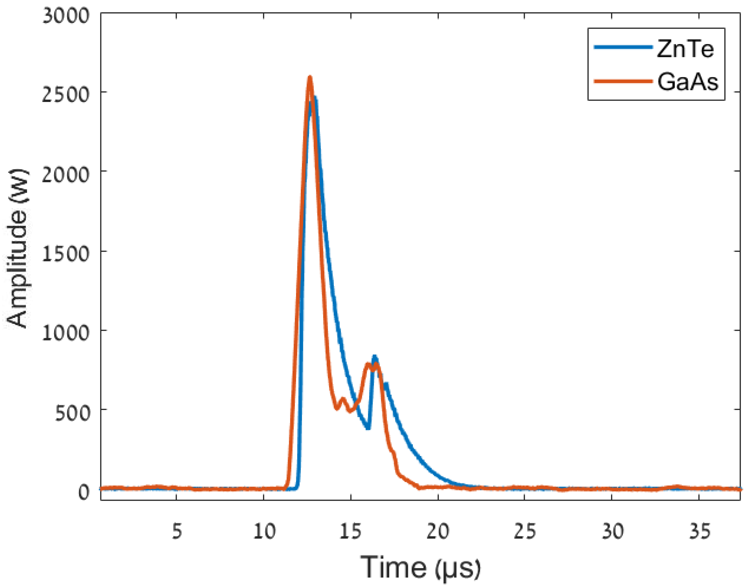
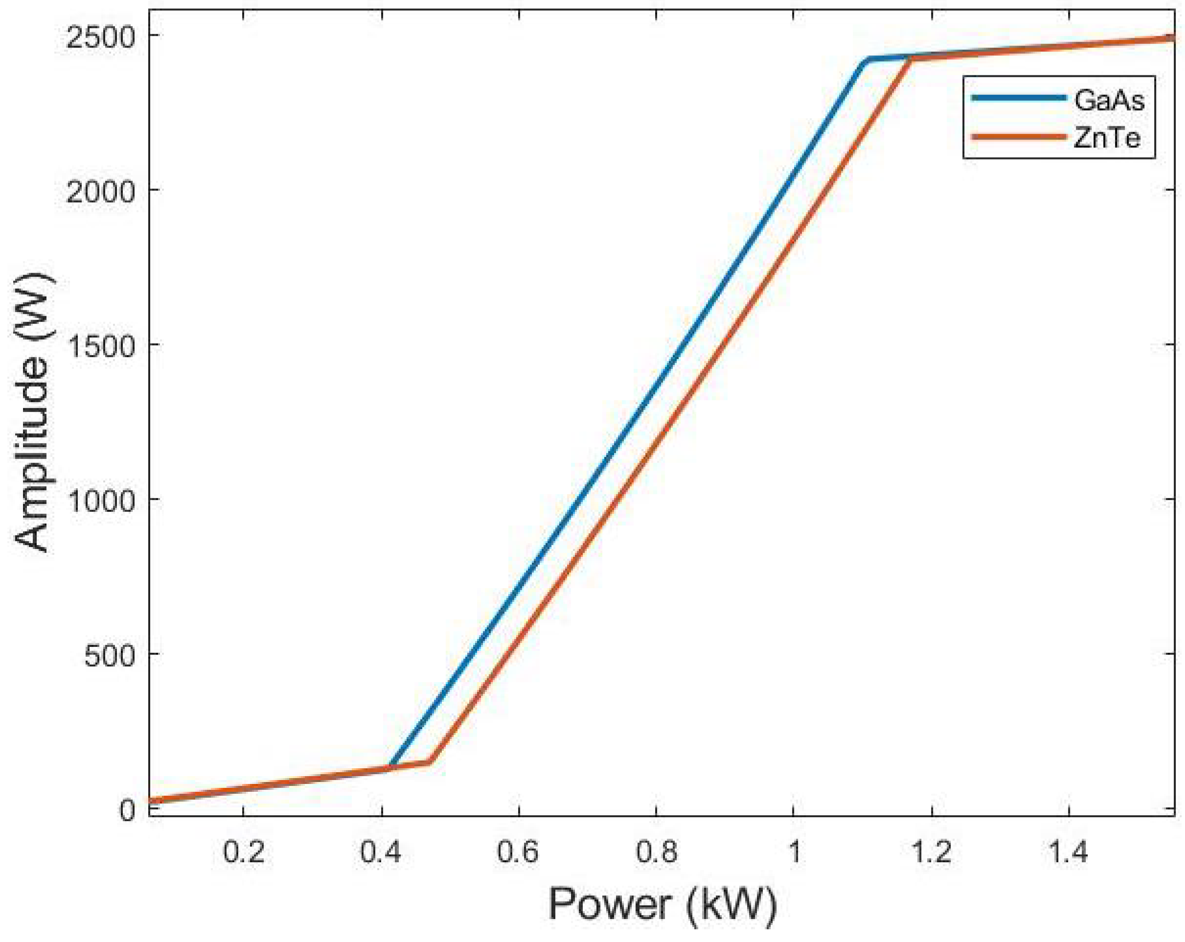
3. Results and Discussion

To ensure that the detection system can detect the THz pulse, it needs to obtain a phase-matching condition. Therefore, the values of n T H z and n g r o u p for ZnTe and GaAs crystals were measured to select the wavelength that maintains a phase-matching condition for each of the ZnTe and GaAs crystals.
It is necessary to ensure a phase-matching condition to obtain an effective comparison between two non-linear crystals. Therefore, we require a Coherence Length of Lc that is as long as possible. Figure 4 shows the Coherence Length Lc for the GaAs and the ZnTe crystals as a function of the laser wavelength. This measurement was performed for 0.11 THz radiation. Figure 4 shows that, for the ZnTe crystal, the Coherence Length is lower for wavelengths greater than 900 nm. Similarly, for GaAs crystals, the Coherence Length is very short at wavelengths smaller than 1300 nm. Therefore, in this experiment, a 635-nm-wavelength laser was used for the ZnTe detection system. A 1550-nm-wavelength laser was used for the GaAs detection system.
Figure 5 illustrates the behavior of the THz refractive index with respect to the group index of the optical pulse as a function of THz radiation. In this measurement, an 635 nm wavelength was used for the ZnTe crystal. An 1550 nm wavelength was used for the GaAs crystal measurement. Figure 5 shows that the ZnTe THz refractive index is congruent with the ZnTe group index up to 2 THz. Electro-optic sampling using a ZnTe crystal and an 635 nm laser can be useful for detecting radiation frequencies up to 2 THz. Likewise, the GaAs THz refractive index can be congruent with the GaAs group index up to 6 THz. This means that GaAs crystals can be useful for electro-optic sampling for the detection of THz radiation with frequencies up to 6 THz.
For an effective comparison between the electro-optic sampling of GaAs and ZnTe, the THz pulse was simultaneously detected by two alternative methods using the electro-optic detectors of the ZnTe and GaAs systems. An H-plane T junction was used in the setup to split the THz pulse. The ZnTe detector system was supplied with 20 dB less than the pulse, and the remaining was supplied to the GaAs system (The splitting system of the THz radiation was shown in [4]). Figure 6 shows the amplitude of the photodiode signal as function of the time. Figure 6 presents the high-power (1 kW) THz pulse detected by the GaAs (red) and (blue) system. The decay time and rise time of the GaAs detector are shorter than those of the ZnTe detector; therefore, the response time of the GaAs is shorter than that of the ZnTe detector. Thus, the GaAs system has a larger bandwidth than the ZnTe system. The rise time of the GaAs detector is 0.65 µs, and the rise time of the ZnTe detector is 0.75 µs. The fiber-coupling method allows for the amplification of the optical signal and the removal of noise around the signal. Which made it possible to receive a clear signal, by which it becomes easier to calculate the rise and decay time. To obtain an effective comparison between the GaAs and ZnTe systems, it is necessary to compare the SNR of both systems. The SNR is given by:
S N R = S E O s i g n a l / N E O n o i s e
where S E O s i g n a l is the obtained signal from the electro-optic detectors, the N E O n o i s e is the noise for the electro-optic detectors. The noise is given by dividing the theoretical signal between the electro-optic signal.
N E O n o i s e = S s i g n a l / S E O s i g n a l
where S s i g n a l is the theoretical signal from the accelerator which obtained from the theoretical simulation of the accelerator. The SNRs of the GaAs and ZnTe systems are 15.66 and 17.5 dB, respectively. The SNR of the GaAs system can be improved using a faster and more sensitive photodetector.
Figure 7 presents the low-power (35 W) THz pulse detected by the GaAs and ZnTe systems. The decay time and rise time of the ZnTe detector are longer than those of the GaAs detector. The rise time of the GaAs detector is 0.6 µs, and the rise time of the ZnTe detector is 0.8 µs. Thus, for low-power and shorter THz pulses, the GaAs detector has better reactivity and a larger bandwidth compared to that of the ZnTe detection system. Although the THz radiation detection by the GaAs system has a bandwidth greater than the ZnTe system, the GaAs system requires a fiber-coupling system to achieve accuracy in THz radiation detection. On the other hand, the coupling of the optical output signal of the electro-optic sampling into the fiber allows us to stretch and detect short THz pulses. Therefore, the GaAs detection system is suitable for the detection of short, single THz pulses, which may facilitate the future wide range of applications of this detection method.
Figure 8 presents the response of each of the detection systems for variable power pulses, i.e, the amplitude of the electric signal of the photo-diode as a function of the THz pulse power. The graph of the visible GaAs detection system is more sensitive to the low-power pulses. On the other hand, the THz pulses of the EA-FEL are high-power pulses. In the case of high-power THz pulses, the sensitivity of each of the ZnTe and the GaAs systems is equal. Therefore, in these cases, the factors of bandwidth and SNR are more interesting.

4. Conclusions

This paper presents the results of high-power MMW/THz pulse detection using electro-optic sampling by GaAs and ZnTe crystals, phase-matching condition calculation, and the determination of a THz range for each of the GaAs and ZnTe crystals in order to obtain a suitable electro-optic detector for the EA-FEL. In the case of the GaAs system, it is necessary to couple the optical pulse with a fiber, which is not necessary in the ZnTe system. However, the results indicate that the GaAs detection system has a shorter response time for electro-optic sampling than the ZnTe system. Furthermore, electro-optic sampling by the GaAs crystal can be used to detect short THz pulses due to fiber coupling. Although the ZnTe detection system has a better SNR, the SNR of the GaAs system can be improved using a faster and more sensitive photodetector, although sensitivity to low-power pulses is not relevant in the case of EA-FEL. However, it can be an important factor in the case of low-power THz systems. It was found that the GaAs detection method is more sensitive to low-power pulses.

Author Contributions

M.G. and A.H.Y. contributed equally to this paper. Conceptualization, A.H.Y.; Methodology, N.B. and M.G.; Data curation, N.B. and M.G.; Investigation, J.C.; Supervision, A.F.; Writing—original draft, A.H.Y. All authors have read and agreed to the published version of the manuscript.

Funding

This research was supported by the Schlesinger Family Center for Compact Accelerators, Ariel University, Israel.

Institutional Review Board Statement

Not applicable.

Informed Consent Statement

Not applicable.

Data Availability Statement

Data are contained within the article.

Conflicts of Interest

The funders had no role in the design of the study; in the collection, analyses, or interpretation of data; in the writing of the manuscript; or in the decision to publish the results.

References

  1. Ashish, Y.; Deepak, D. Terahertz technology and its applications. Drug Invent. Today 2013, 5, 157–163. [Google Scholar]
  2. Hafez1, H.; Chai, X.; Ibrahim, A. Intense terahertz radiation and their applications. J. Opt. 2016, 18, 093004. [Google Scholar] [CrossRef]
  3. Gabriel, M. Millimeter-Wave and Terahertz Integrated Circuit Antennas. Proc. IEEE 1992, 80, 1748–1770. [Google Scholar]
  4. Haj Yahya, A.; Avi, K. Comparison between up-conversion detection in glow-discharge detectors and the Schottky diode for MMW/THz high-power single pulse. Appl. Sci. 2021, 11, 4172. [Google Scholar] [CrossRef]
  5. Rogalski, A.; Sizov, F. Terahertz detectors and focal plane arrays. Opt. Electron. Rev. 2011, 19, 346–404. [Google Scholar] [CrossRef]
  6. Hou, L.; Hi, W. Fast THz continuous-wave detector based on weakly ionized plasma. IEEE Electron. Device Lett. 2012, 52, 1583–1585. [Google Scholar] [CrossRef]
  7. Jiang, Z.; Zhang, X.-C. Terahertz imaging via electro-optic effect. IEEE Trans. Microw. Theory Tech. 1999, 47, 2644–2650. [Google Scholar] [CrossRef] [Green Version]
  8. Pradarutti, B.; Matthäus, G. Highly efficient terahertz electro-optic sampling by material optimization at 1060 nm. Opt. Commun. 2008, 281, 5031–5035. [Google Scholar] [CrossRef]
  9. Wu, Q.; Zhanga, X. Free-space electro-optic sampling of terahertz beams. Appl. Phys. Lett. 1995, 67, 3523–3525. [Google Scholar] [CrossRef]
  10. Zhao, G.; Schouten, R.N. Design and performance of a THz emission and detection setup based on a semi-insulating GaAs emitter. Rev. Sci. Instrum. 2002, 73, 1715–1719. [Google Scholar] [CrossRef] [Green Version]
  11. Dexheimer, S.L. Principles and Applications. In Terahertz Spectroscopy, 1st ed.; CRC Press Taylor and Francis Group: Boca Raton, FL, USA, 2008; p. 360. [Google Scholar]
  12. Sabine, K.; Shawn, S. Electro-optic sampling of near-infrared waveforms. Nat. Photonics 2016, 10, 159–163. [Google Scholar]
  13. Tomasino, A.; Parisi, A. Wideband THz Time Domain Spectroscopy based on Optical Rectification and Electro-Optic Sampling. Sci. Rep. 2013, 3, 3116. [Google Scholar] [CrossRef] [PubMed] [Green Version]
  14. Bang, W.; Lei, C. Comparison of the detection performance of three nonlinear crystals for the electro-optic sampling of a FEL-THz source. In Proceedings of the 5th International Particle Accelerator Conference (IPAC 2014), Dresden, Germany, 15–20 June 2014; Volume 17, pp. 2891–2893. [Google Scholar]
  15. Xie, X.; Xu, J.; Zhang, X.-C. Terahertz wave generation and detection from a CdTe crystal characterized by different excitation wavelengths. Opt. Lett. 2006, 31, 978–980. [Google Scholar] [CrossRef] [PubMed]
  16. Kodo, K.; Manabu, S. Unidirectional radiation of widely tunable THz wave using a prism coupler under noncollinear phase matching condition. Appl. Phys. Lett. 1997, 71, 753–755. [Google Scholar]
  17. Ajay, N.; Aniruddha, S.W. A wideband coherent terahertz spectroscopy system using optical rectification and electro-optic sampling. Appl. Phys. Lett. 1996, 69, 2321–2323. [Google Scholar]
  18. Masaya, N.; Koichiro, T. Generation and detection of terahertz radiation by electro-optical process in GaAs using 1.56 mm fiber laser pulses. Appl. Phys. Lett. 2004, 85, 3974–3976. [Google Scholar]
  19. Marks, H.; Gover, A.; Lurie, Y. Enhancement Of Radiative Energy Extraction In An FEL Oscillartor by Post-Saturation Beam Energy Ramping. In Proceedings of the 38th Interntional Free Elctron Laser Conference, Santa Fe, NM, USA, 20–25 August 2017; pp. 244–246. [Google Scholar]
  20. Haj Yahya, A.; Avi, K. Improvement of the electro-optical process in GaAs for terahertz single pulse detection by using a fiber-coupling system. Appl. Sci. 2021, 11, 6859. [Google Scholar] [CrossRef]
  21. Marks, H.S.; Gover, A. Radiation Power Out-Coupling Optimization of a Free Electron Laser Oscillator. IEEE Trans. Microw. Theory Tech. 2016, 64, 1006–1014. [Google Scholar] [CrossRef]
  22. Liu, S.-G.; Liu, H.-X. Electrostatic free-electron laser. Phys. Rev. A 1987, 36, 3837. [Google Scholar] [CrossRef]
  23. Marks, M.; Borodin, D. Power and spectral evolution of a Free Electron Laser oscillator with electron beam energy ramping. Nuclear Inst. Methods Phys. Res. A 2021, 1004, 165376. [Google Scholar] [CrossRef]
  24. Marks, M.; Gover, A. Talbot Effect mm-Wave Resonator for an Electrostatic Accelerator Free Electron Laser. IEEE Trans. Microw. Theory Tech. 2018, 66, 3–10. [Google Scholar] [CrossRef]
Figure 1. Schematic of the ZnTe electro-optic detector.
Designs 06 00109 g001
Figure 2. Schematic of the GaAs electro-optic detector.
Designs 06 00109 g002
Figure 3. Schematic of the electrostatic accelerator FEL.
Designs 06 00109 g003
Figure 4. The coherence length for the GaAs and the ZnTe crystals.
Designs 06 00109 g004
Figure 5. THz refractive index and group refractive index of the GaAs and the ZnTe crystals.
Designs 06 00109 g005
Figure 6. High-power THz pulse detection by electro-optic sampling using GaAs and ZnTe.
Designs 06 00109 g006
Figure 7. Low-power THz pulse detection by the electro-optic sampling using GaAs, ZnTe.
Designs 06 00109 g007
Figure 8. The power responsivity for the electro-optic detectors.
Designs 06 00109 g008
Table 1. Optical refractive index parameters [18].
Parameter 1ZnTeGaAsGaP
A4.278.952.680
B3.012.0546.40
D0.1420.390.090327
Table 2. Israeli EA-FEL properties.
ParameterValue
Radiation Frequency95–110 GHz
Beam Energy1.35–1.45 MeV
Beam Current0.7–3 A
Free Spectral Range100 MHz
Publisher’s Note: MDPI stays neutral with regard to jurisdictional claims in published maps and institutional affiliations.

