Preliminary Analysis of a New Power Train Concept for a City Hybrid Vehicle
Abstract
1. Introduction
2. The Proposed Task
- (1)
- For turbine stages, the focus is on the investigation and development of technologies that would improve on-engine exhaust energy utilization compared to the conventional radial turbines in widespread use today;
- (2)
- For compressor stages, the focus is on investigating compressor design parameters beyond the range typically utilized in production (i.e., higher pressure ratios), to determine the potential efficiency benefits thereof;
- (3)
- For TC units, the focus is on the development of a robust bearing system that would provide higher bearing efficiencies compared to systems used in turbo-compound power turbines in production.
3. Turbocompressor Specifications
- It calculates the design volumetric suction flow rate (calculated at “standard conditions” specified by design standards);
- Once the flow rate and the pressure ratio are known, the preliminary “shape” of the compressor occurs; the specific work is given by:
- Based on the type of compressor, the tentative maximum peripheral speed, Umax, is fixed and the necessary Euler’s work is obtained:
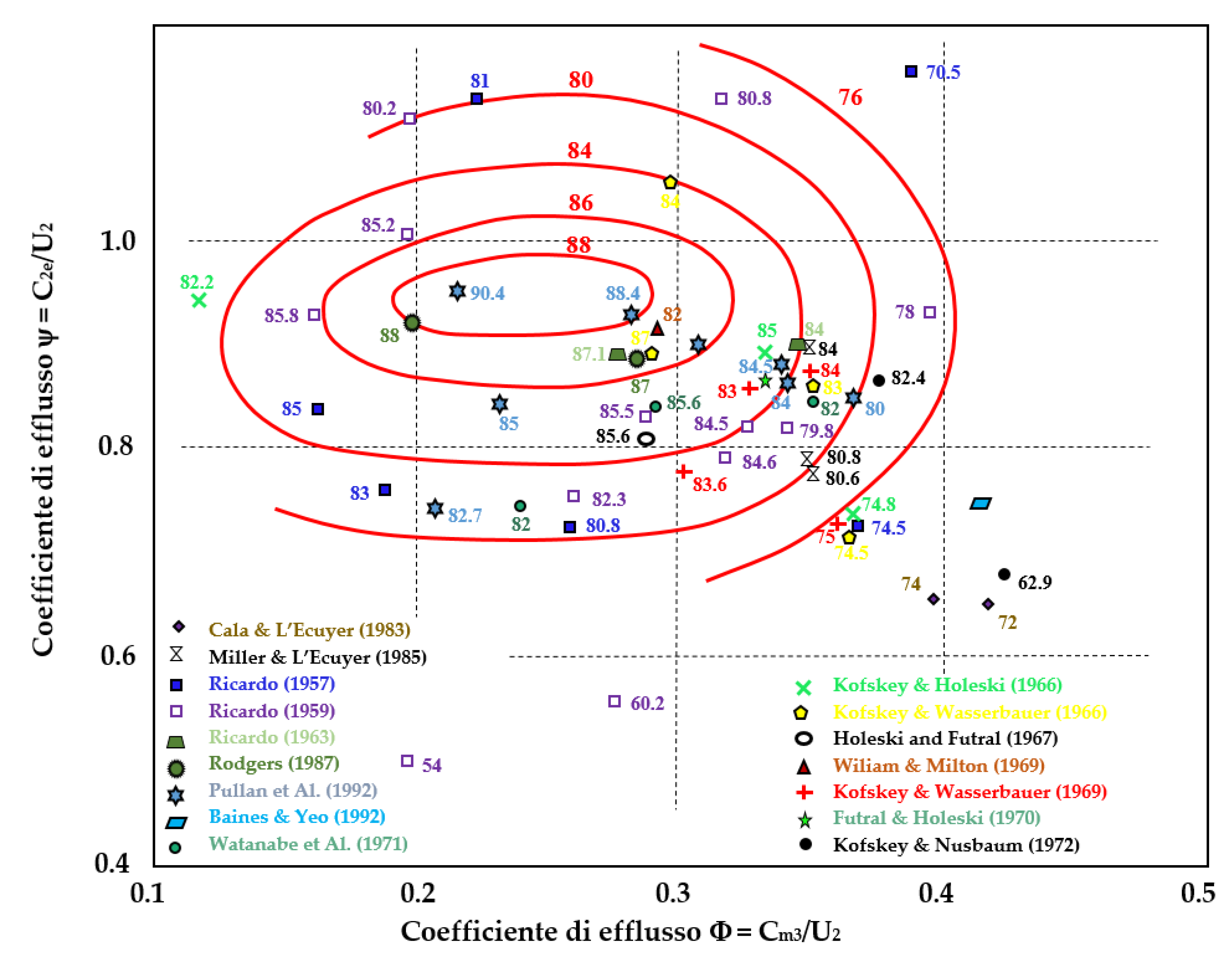
- If the value of the ψ2 obtained from the calculation is acceptable (i.e., falls within the field of values historically adopted in similar machines with technically satisfactory results), only one stage will be sufficient. Otherwise, there are two possibilities:
- (a)
- To increase the Umax, choosing a different geometry and return to step 3;
- (b)
- To keep the specification values for Umax and ψ2, and calculate the number of stages from the equation:
- (a)
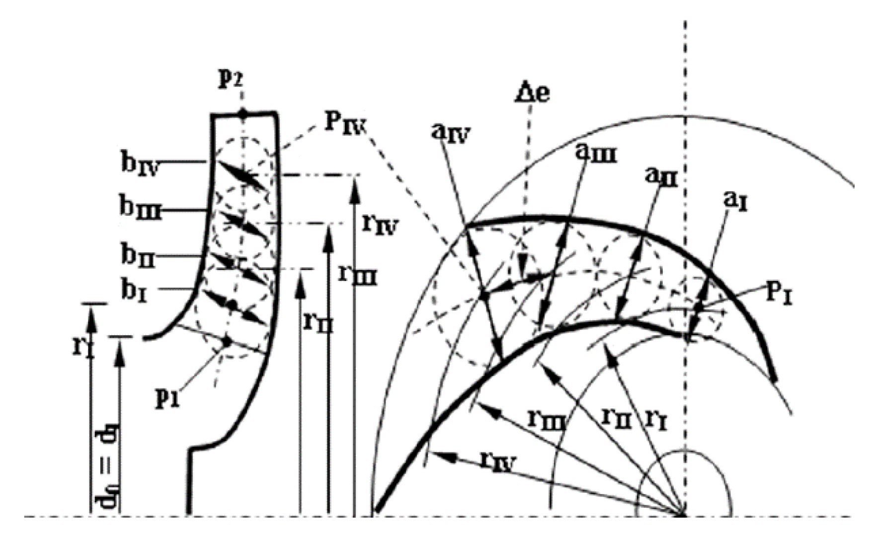
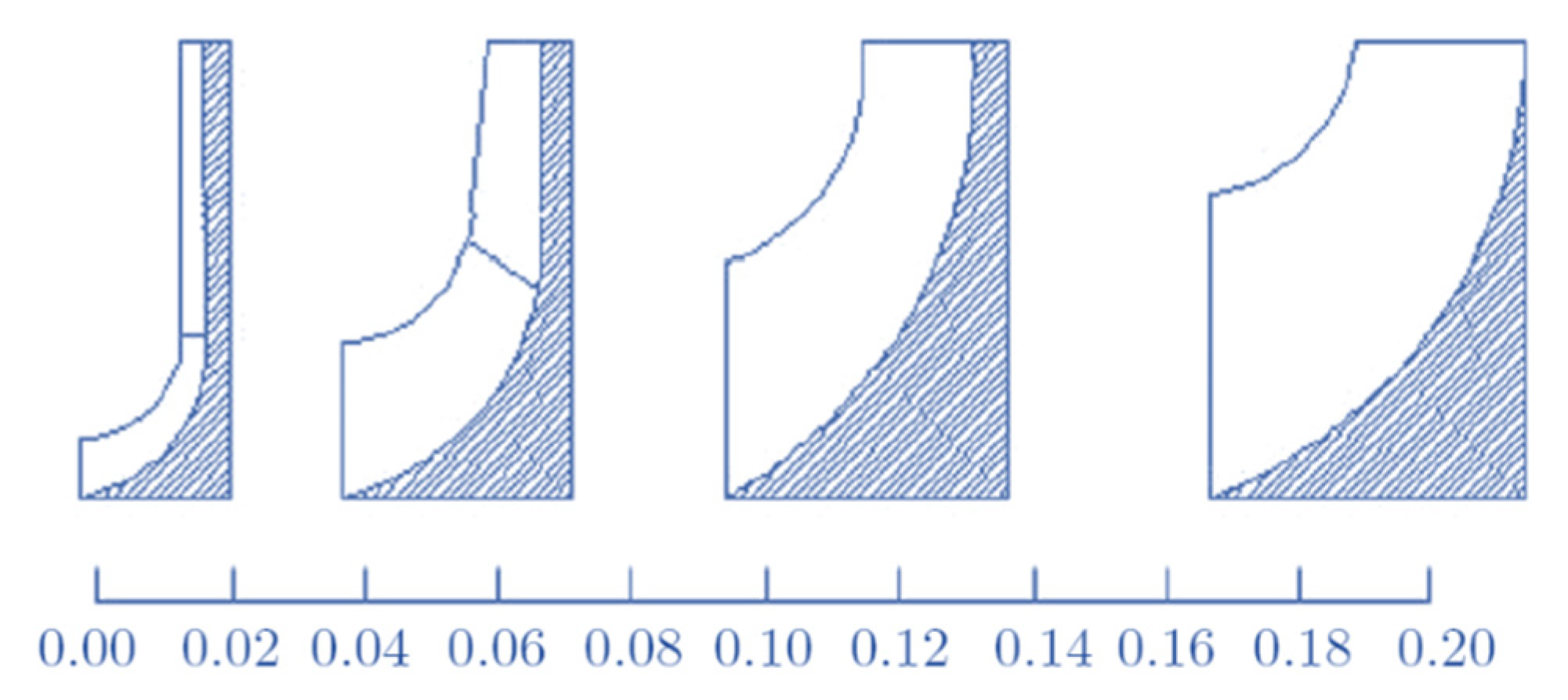
- the channel projection on the meridian section is calculated using a midline drawn by polynomial interpolation methods. The exact shape of the tracks on the meridian plane of the intersections of the hub and the case is obtained in two stages. In addition to any variations of δp with s, that can be (in the first approximation) neglected, the volumetric flow Q varies with s, due to the variation in the specific volume of the fluid during compression. The trend of p with s cannot be calculated exactly, and therefore it is estimated from the transformation diagram in the s/h plane. Once the trend of the passage area along the meridian line is known, the envelope of the circles of radius b(s) = A(s)/(2πr) is constructed. These two envelopes (one on the case side and the other on the hub), make up the walls of the canal.
- (b)
- The shape of the channel in the front view is based on the definition of a midline too: both blades with an Archimedes spiral (logarithmic) as the front profile can be adopted, that is, with the characteristic of forming a constant angle θ with the radius throughout its development, as well as profiles of arc circle blades or polycmetric arcs. Having chosen the number of blades, the front section remains automatically defined.
4. Turbine Definition
- the motion is permanent and stationary;
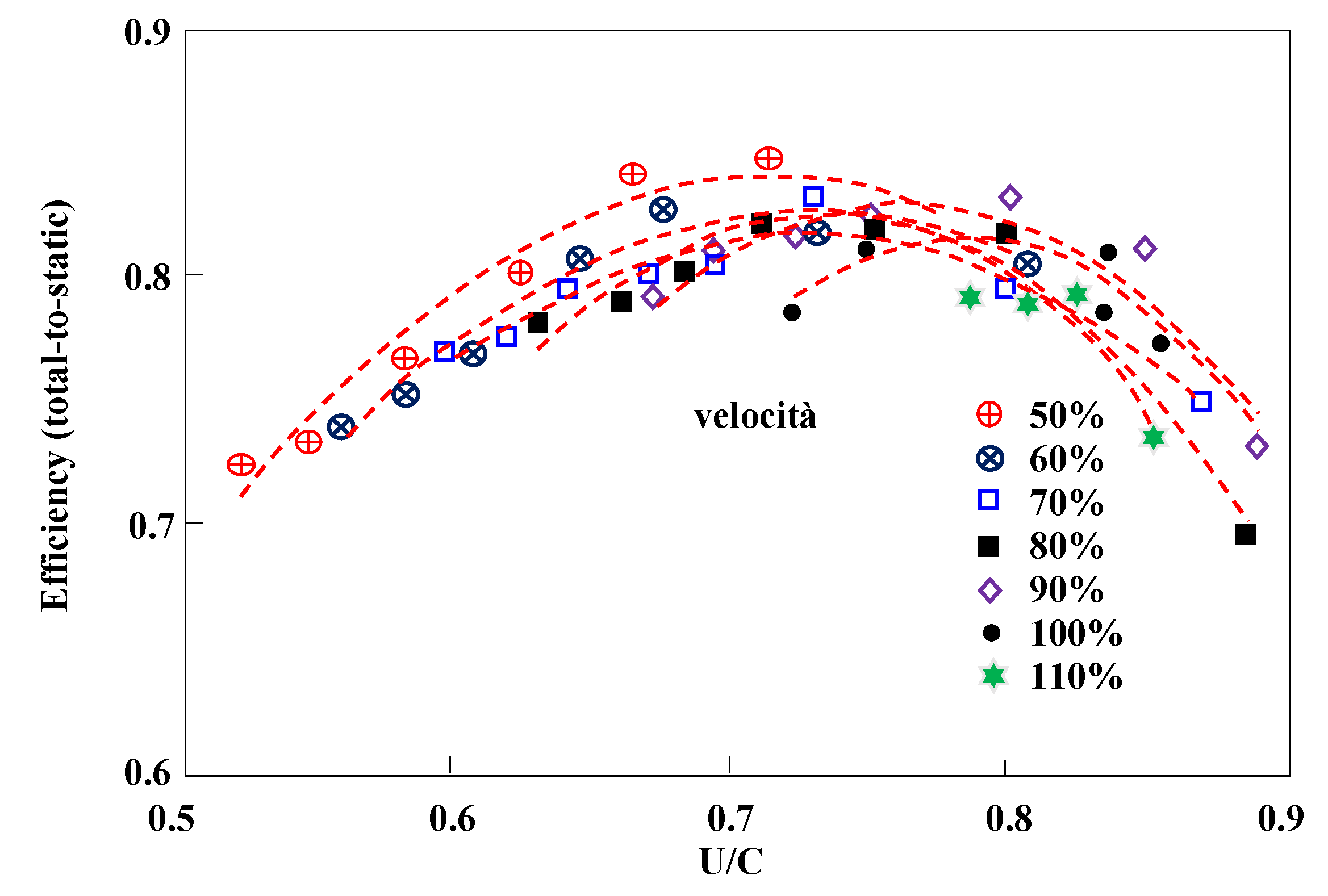
- the speed is constant on the exhaust section, or, if post-rotation is adopted, the law of variation of V2t with the radius is known;
- the motion in the fixed channels takes place by cylindrical flaps, and in the mobile channels for helical flaps;
- the speed is constant on the supply section.
- (a)
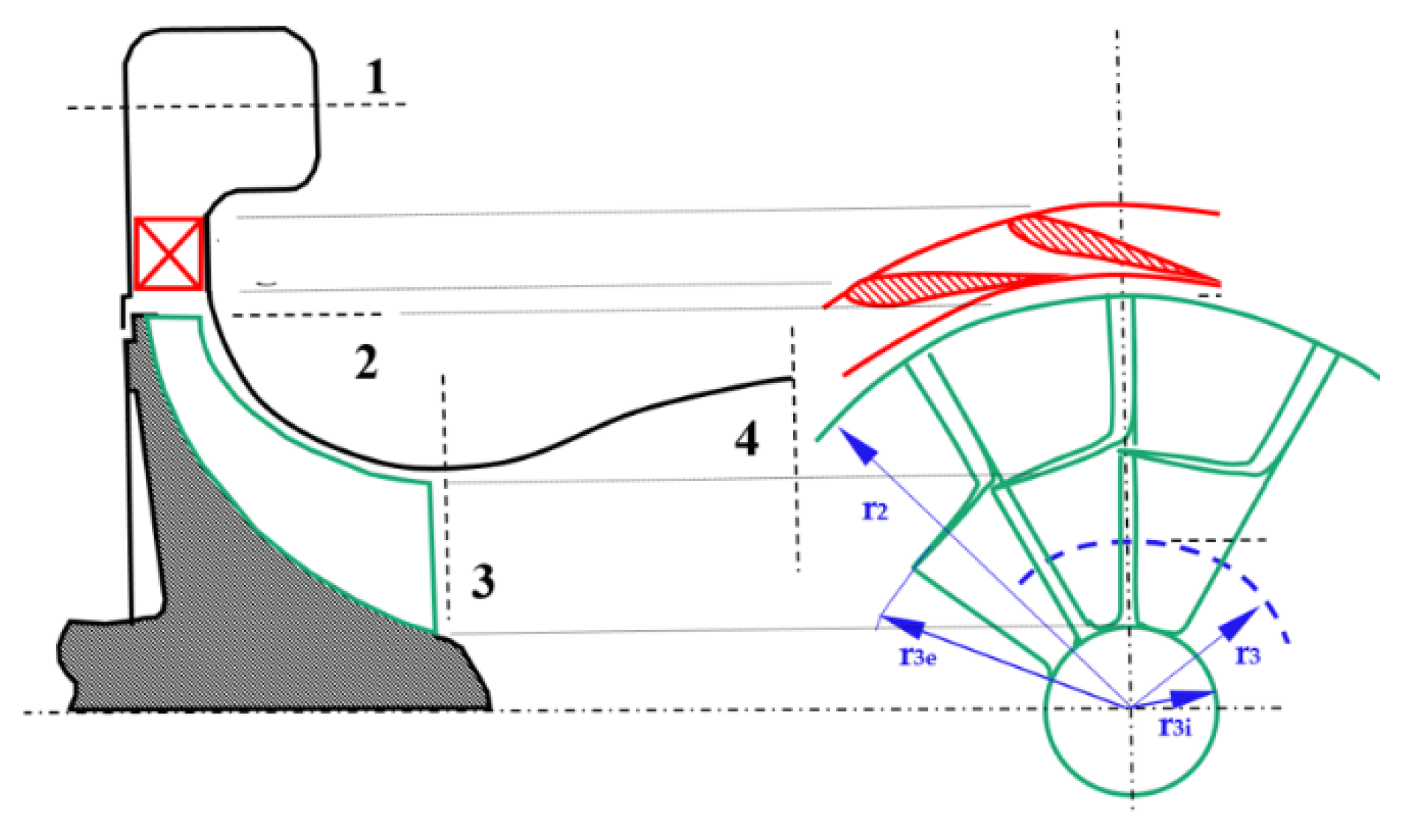
- the general shape of the channel in the meridian section is calculated on the basis of an average meridian line drawn by appropriate polynomial interpolation methods in a manner similar to what is seen in turbocompressors;
- (b)
- the exact shape of the traces on the meridian plane of the intersections of the hub and the case is obtained in two stages: first the law of the passage area is fixed, it is established as the area useful for the disposal of the various flow rate with the curvilinear axle measured along the medium meridian line. In fact, it is advisable to fix the law of variation of the meridian velocity Vm. Fixing A(s) the area at the abscissa s, results A(s) = Q/(Vm δp). In this case, the volumetric flow Q varies with s, due to the variation in the specific volume of the fluid during expansion. Finally, the envelope of the radius circles b(s) = A(s)/(2nr) is constructed: these two envelopes (one on the case side and the other on the hub side), make up the walls of the channel. The shape of the channel, in the front view, is also based on the definition of a midline: the profiles adopted are all chosen on the basis of structural resistance considerations, and therefore have the least possible curvatures. Widely used as a front profile is the Archimedes spiral (logarithmic), but mixed profile blades are also used, with a straight and a circular arch stroke. Having chosen the number of blades, the front section remains automatically defined.
5. Preliminary Analysis and Future Development
6. Conclusions
Funding
Conflicts of Interest
Nomenclature
| c | Specific Heat [J/kg K] |
| CFD | Computational Fluid Dynamic |
| FEM | Finite Elements |
| GT | Gas Turbine |
| ICE | Internal Combustion Engine |
| KERS | Kinetic Energy Recovery System |
| m | Mass Flow rate [kg/s] |
| N | Number of stages |
| n | Rotational speed |
| p | Pressure [Pa] |
| P | Power [W] |
| Q | Volumetric Flow rate [m3/s] |
| r | Radius [m] |
| R | Reaction degree |
| rpm | Revolutions per minute |
| U | Peripheral Velocity [m/s] |
| V | Absolute Velocity [m/s] |
| T | Temperature [K] |
| TC | Turbo compressor |
| W | Work [J/kg] |
| Greek Letter | |
| β | Compression ratio |
| χ | Hub to shroud ratio |
| δ | Blockage factor |
| η | Efficiency |
| φ | Flow Coefficient |
| ρ | Density [kg/m3] |
| ψ | Load Coefficient |
| ω | angular speed [rad/s] |
| Subscripts | |
| 1 | Inlet/Outlet section |
| 2 | Inlet/Outlet section |
| EUL | Eulerian |
| in | Inlet |
| out | Outlet |
| s | Specific |
References
- Zhao, D.; Winward, E.; Yang, Z.; Stobart, R. Decoupling Control of Electrified Turbocharged Diesel Engines. In Proceedings of the American Control Conference, Boston, MA, USA, 6–8 July 2016. [Google Scholar] [CrossRef]
- Gödeke, H.; Prevedel, K. Hybrid Turbocharger with Innovative Electric Motor. MTZ Worldw. 2014, 75, 26–31. [Google Scholar] [CrossRef]
- Chen, S.; Yan, F. Decoupled, Disturbance Rejection Control for A Turbocharged Diesel Engine with Dual-loop EGR System. IFAC-PapersOnLine 2016, 49, 619–624. [Google Scholar] [CrossRef]
- Jain, A.A.; Nueesch, T.; Naegele, C.; Lassus, P.M.; Onder, C.H. Modeling and Control of a Hybrid Electric Vehicle with an Electrically Assisted Turbocharger. IEEE Trans. Veh. Technol. 2016, 65, 4344–4358. [Google Scholar] [CrossRef]
- Balje, O. Turbomachines; John Wiley & Sons: Hoboken, NJ, USA, 1981. [Google Scholar]
- Shepherd, D.G. Principles of Turbomachinery; J. Macmillan Pub. Co.: New York, NY, USA, 1956. [Google Scholar]
- ATIP Scoop, Japan Office, Micro Gas Turbine Development. Available online: https://www.linkedin.com/company/asian-technology-information-program-atip-/ (accessed on 1 October 2020).
- Peirs, J.; Reynaerts, D.; Verplaetsen, F.; Norman, F.; Lefever, S. Development of a Micro Gas Turbine for Electric Power Generation. In Proceedings of the 14th Micromechanics Europe Workshop, Delfi, The Netherlands, 2–4 November 2003. [Google Scholar]
- Ishihama, M.; Sakai, I.; Matsuzuki, K.; Hikone, T. Structural Analysis of Rotating Parts of An Ultra Micro Gas Turbine. In Proceedings of the International Gas Turbine Congress 2003, Tokyo, Japan, 2–7 November 2003. [Google Scholar]
- Gaydamaka, I.V.; Efimov, A.V.; Ivanov, M.J.; Ivanov, O.I.; Nigmatullin, R.Z.; Ogarko, N.I. Some Aerodynamic Performances of Small Size Compressor and Turbine Stages. In Proceedings of the International Gas Turbine Congress 2003, Tokyo, Japan, 2–7 November 2003. [Google Scholar]
- Van den Braembussche, R.A. Thermo-Fluid-Dynamic Design of Ultra Micro Gas-Turbine Components. Available online: https://www.vki.ac.be/index.php/264-faculty/faculty-in-tu/417-rene-van-den-braembussche (accessed on 1 December 2019).
- Cuturi, N.; Sciubba, E. Improvements in the design of a tandem compressor for an innovative turbocharger configuration for a hybrid city car. Int. J. Turbomach. Propuls. Power 2020, in press. [Google Scholar]
- Matsuura, K.; Kato, C.; Yoshiki, H.; Matsuo, E.; Ikeda, H.; Nishimura, K.; Sapkota, R. Prototyping of Small-Sized Two Dimensional Radial Turbines. In Proceedings of the International Gas Turbine Congress 2003, Tokyo, Japan, 2–7 November 2003. [Google Scholar]
- Dixon, S.L.; Hall, C.A. Fluid Mechanics and Thermodynamics of Turbomachinery; Butterworth-Heinemann Pub.: Oxford, UK, 2010; ISBN 978-1-85617-793-1. [Google Scholar] [CrossRef]
- Frechette, L.G.; Jacobson, S.A.; Breuer, S.K.; Ehrich, F.F.; Ghodssi, R.; Khanna, R.; Wong, C.W.; Zhang, X.; Schimdt, M.A.; Epstein, A.H. High-Speed Micro-Fabricated Silicon Turbomachinery and Fluid Film Bearings. J. Microelectromechanical Syst. 2005, 14, 141–152. [Google Scholar] [CrossRef]
- Iwai, M. Thermodynamic Table for Performance Calculations in Gas Turbine Engine. In Proceedings of the International Gas Turbine Congress 2003, Tokyo, Japan, 2–7 November 2003. [Google Scholar]
- O’Brien, P. Development of a 50-kW, Low-Emission Turbogenerator for Hybrid Electric Vehicles. In Proceedings of the Conference of ASME 1998 International Gas Turbine and Aeroengine Congress and Exhibition, Stockholm, Sweden, 23 December 2014. Paper No.: 98-GT-400, V002T04A009; 6 pages. [Google Scholar] [CrossRef]
- Silvestri, T. CFD Analysis of a Radial Turbine Stage with Variable NGV Control. Master’s Thesis, Deptartment of Mechanical and Aerospace Engineering, University of Roma Sapienza, Roma, Italy, 2020. [Google Scholar]
- Capata, R.; Sciubba, E. The low emission Turbogas hybrid vehicle concept-preliminary simulation and vehicle packaging. J. Energy Resour. Technol. 2013, 135, 032203. [Google Scholar] [CrossRef]
- Fontaras, G.; Pistikopoulos, P.; Samaras, Z. Experimental evaluation of hybrid vehicle fuel economy and pollutant emissions over real-world simulation driving cycles. Atmos. Environ. 2008, 42, 4023–4035. [Google Scholar] [CrossRef]
- Oshiro, K.; Masui, T. Diffusion of low emission vehicles and their impact on CO2 emission reduction in Japan. Energy Policy 2015, 81, 215–225. [Google Scholar] [CrossRef]
- Capata, R. Urban and extra-urban hybrid vehicles: A technological review. Energies 2018, 11, 2924. [Google Scholar] [CrossRef]
- Capata, R. New Power Train Concept for a City Hybrid Vehicle. Proceedings 2020, 58, 6. [Google Scholar] [CrossRef]

| [kg/s] | 0.02 | WEUL [J/kg] | 44,652.74 | ψ2 | 1 |
| β | 1.4 | U2 [m/s] | 211.31 | ψ1 | 0 |
| cp [J/kg K] | 1004 | r2 [m] | 0.0144 | φ1 | 0.3 |
| T1 [K] | 293 | ΔΤ | 22.2 | φ2 | 0.55 |
| ω [rad/s] | 14,653 | ρ1 [kg/m3] | 1.20 | δp | 0.98 |
| ε | 0.42 | 1 [m3/s] | 0.0167 | Rρ | 0.5 |
| p1 [Pa] | 101,000 | r1e [m] | 0.0110 | χ | 0.65 |
| T2 [K] | 337 | r1i [m] | 0.0072 | (1 − χ2) | 0.58 |
| rpm ICE | [kg/s] | rpm | βc | Tin [K] | Tout [K] | P [W] | η |
|---|---|---|---|---|---|---|---|
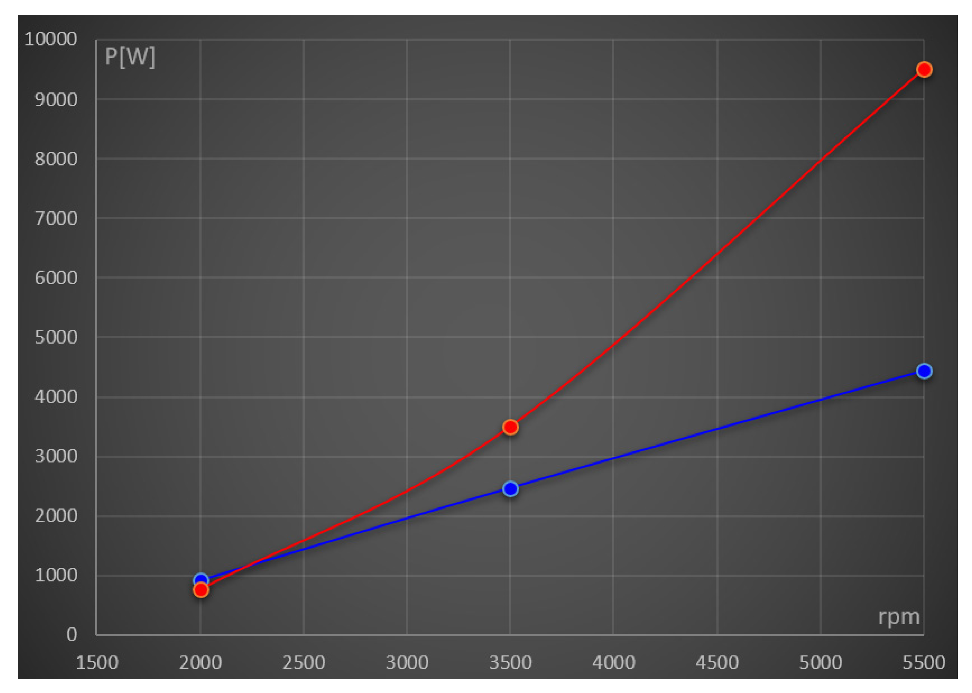
| 2000 | 0.021 | 145,000 | 1.42 | 298.4 | 344 | 920.71 | 0.68 |
| 3500 | 0.0408 | 180,000 | 1.64 | 297.5 | 354 | 2474.39 | 0.8 |
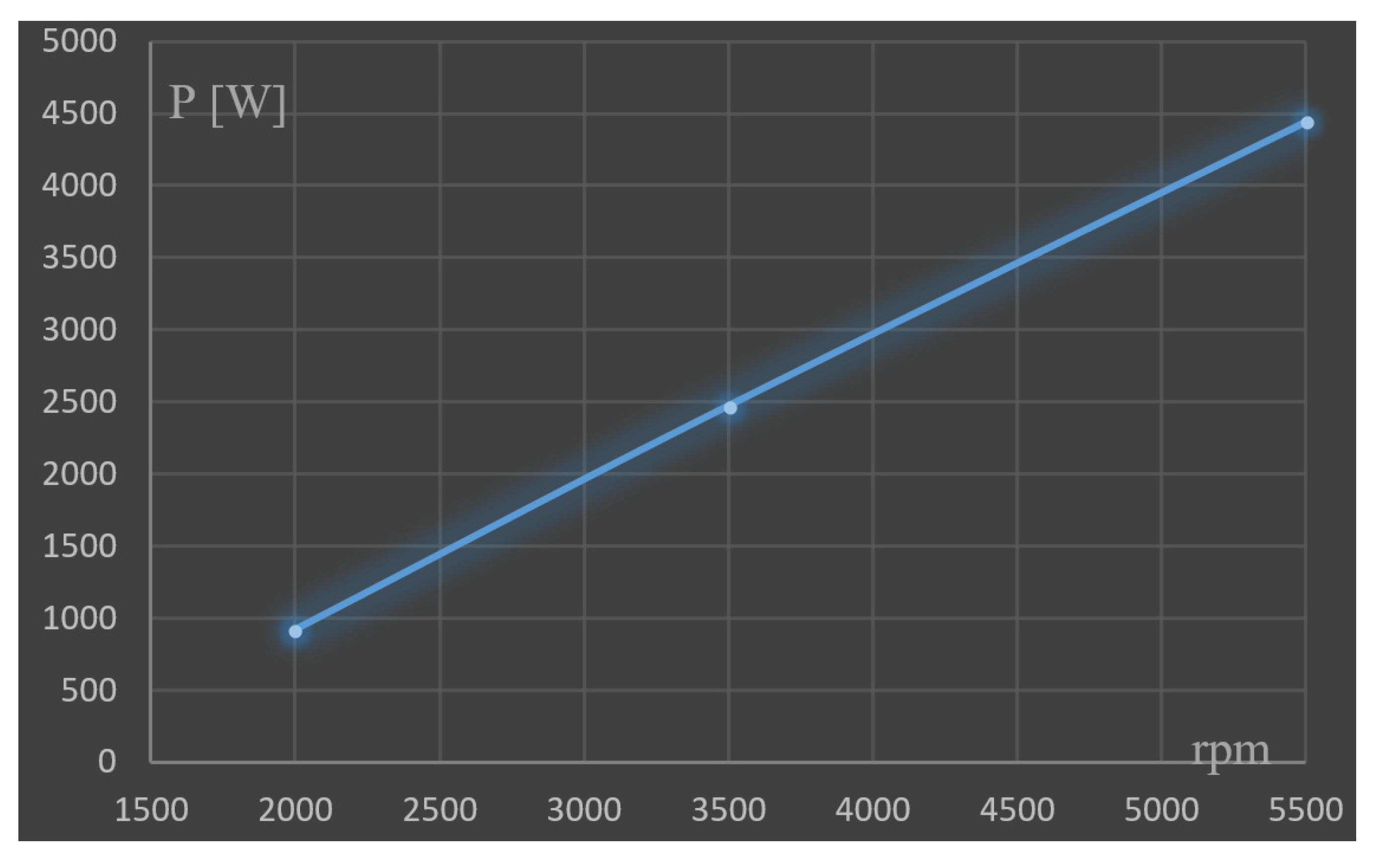
| 5500 | 0.0619 | 210,000 | 1.84 | 297.5 | 366.8 | 4444.96 | 0.82 |
| [kg/s] | 0.0021 | WEUL [J/kg] | 103,194.4 | ψ1 | 1 |
| β | 1.4 | U2 [m/s] | 321.24 | ψ2 | 0 |
| cp [J/kg K] | 1414 | r2 [m] | 0.051 | φ1 | 0.3 |
| T1 [K] | 980 | ΔΤ | 36.4 | φ2 | 0.4 |
| ω [rad/s] | 6280 | ρ2 [kg/m3] | 0.39 | δp | 0.98 |
| ε | 0.23 | 1 [m3/s] | 0.0054 | Rρ | 0.5 |
| p2 [Pa] | 101,000 | r2e [m] | 0.0112 | χ | 0.65 |
| T2 [K] | 907 | r2i [m] | 0.0072 | (1 − χ2) | 0.58 |
| rpm ICE | [kg/s] | rpm | βe | Tin [K] | Tout [K] | P [W] | η |
|---|---|---|---|---|---|---|---|
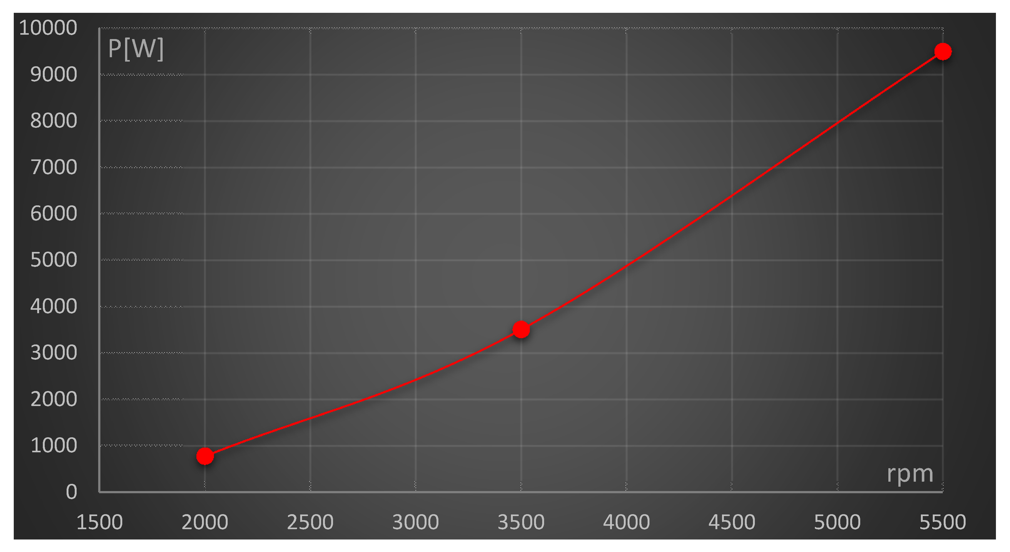
| 2000 | 0.024 | 82,170 | 1.2 | 954 | 922 | 780 | 0.87 |
| 3500 | 0.04 | 134,483 | 1.6 | 1005 | 930 | 3510 | 0.86 |
| 5500 | 0.07 | 164,002 | 2.00 | 1045 | 932 | 9500 | 0.81 |
Publisher’s Note: MDPI stays neutral with regard to jurisdictional claims in published maps and institutional affiliations. |
© 2021 by the author. Licensee MDPI, Basel, Switzerland. This article is an open access article distributed under the terms and conditions of the Creative Commons Attribution (CC BY) license (http://creativecommons.org/licenses/by/4.0/).
Share and Cite
Capata, R. Preliminary Analysis of a New Power Train Concept for a City Hybrid Vehicle. Designs 2021, 5, 19. https://doi.org/10.3390/designs5010019
Capata R. Preliminary Analysis of a New Power Train Concept for a City Hybrid Vehicle. Designs. 2021; 5(1):19. https://doi.org/10.3390/designs5010019
Chicago/Turabian StyleCapata, Roberto. 2021. "Preliminary Analysis of a New Power Train Concept for a City Hybrid Vehicle" Designs 5, no. 1: 19. https://doi.org/10.3390/designs5010019
APA StyleCapata, R. (2021). Preliminary Analysis of a New Power Train Concept for a City Hybrid Vehicle. Designs, 5(1), 19. https://doi.org/10.3390/designs5010019


