Article

Design and Analysis of Porous Functionally Graded Femoral Prostheses with Improved Stress Shielding

by
Morassa Jafari Chashmi
1,
Alireza Fathi
1,
Masoud Shirzad
1,2,
Ramazan-Ali Jafari-Talookolaei
1,
Mahdi Bodaghi
2,* and
Sayed Mahmood Rabiee
3
1
Department of Mechanical Engineering, Babol Noshirvani University of Technology, Babol 47148-71167, Iran
2
Department of Engineering, School of Science and Technology, Nottingham Trent University, Nottingham NG11 8NS, UK
3
Department of Materials Engineering, Babol Noshirvani University of Technology, Babol 47148-71167, Iran
*
Author to whom correspondence should be addressed.
Designs 2020, 4(2), 12; https://doi.org/10.3390/designs4020012
Submission received: 15 April 2020 / Revised: 5 May 2020 / Accepted: 29 May 2020 / Published: 2 June 2020

Abstract

:
One of the most important problems of total hip replacement is aseptic loosening of the femoral component, which is related to the changes of the stress distribution pattern after implantation of the prosthesis. Stress shielding of the femur is recognized as a primary factor in aseptic loosening of hip replacements. Utilizing different materials is one of the ordinary solutions for that problem, but using functionally graded materials (FGMs) could be better than the conventional solutions. This research work aims at investigating different porous FGM implants and a real femoral bone by a 3D finite element method. The results show that a neutral functionally graded prosthesis cannot extraordinarily make changes in the stress pattern of bone and prosthesis, but an increasing functionally graded prosthesis leads a lower level of stress in the prosthesis, and a decreasing functionally graded prosthesis can properly reduce the stress shielding among these three architectures. Due to the absence of similar results in the specialized literature, this paper is likely to fill a gap in the state-of-the-art bio-implants, and provide pertinent results that are instrumental in the design of porous femoral prostheses under normal walking loading conditions.

1. Introduction

Total hip replacement (THR) is known as the last solution for patients and can be helpful to relieve pain, restore function, and improve the quality of life for patients when conservative treatments have lost their efficacy. Despite the success of THR, there are some reasons that can negatively affect the utilizing of this treatment, such as stress shielding and aseptic loosening [1,2,3,4]. The mismatch between the stiffness of the bone and the inserted prosthesis can lead to a variation of the bone stress pattern. Additionally, the prosthesis is usually stiffer than the surrounded bone; therefore, the stress in the bone cannot reach an appropriate level, and it can cause bone resorption. This is a common process which is regarded as “stress shielding” [5,6]. The stress shielding of the prosthesis leads to the reduction of the strength of the cortical structure of the bone, and it can also cause aseptic loosening, which is one of the main reasons for failure of THRs [7,8]. There are many studies conducted to identify an appropriate material for fabricating prostheses and minimizing the stress shielding. In this regard, composite materials have been utilized in femoral prostheses [9,10,11]. Among the proposed composite materials, functionally graded materials (FGMs) have shown the most appropriate characteristics compared to the other composites because their excellent properties let them minimize the stress shielding [12,13,14]. The concept of FGMs originally stems from the hierarchical structures of the bones [15,16]. Additionally, their mechanical properties can be controlled and optimized by altering the volume fraction of each section to improve the biocompatibility, fracture toughness, and wearing resistance, which are extremely important for biomedical applications [17,18,19,20,21]. Porous architecture can be utilized to mimic FGM characteristics, and its medium increases the possibility of bone ingrowth and ensures prosthesis firm fixation in the implantation site. Based on the references mentioned above, triply periodic minimal surfaces (TPMS) can be a promising option for the tissue engineering scaffolds because they have many advantages in comparison with common structures like honeycombs and strut-based lattices. The structure of TPMS has the unique combination of properties consisting of high surface-to-volume ratio and stiffness-to-weight ratio, and their pores can easily be altered to a functionally graded (FG) architecture [22,23,24].
The prosthetic design safety and its mechanical behavior can be evaluated by some common analyses such as experimental and numerical procedures. The finite element method (FEM) is one of the main reliable means that can give promising results [3,25,26]. Typically, static FEMs are conducted by loads with a magnitude proportional with the body weight [27]; however, the negative influence of weight can escalate when it is followed by a movement. In the other words, the prosthesis should be investigated under a specific condition, rather than just static loading of the body weight [28,29].
In the present study, an FEM is developed to evaluate a model of a femur implanted with a porous functionally graded prosthesis considering normal walking loading conditions. Beside the FG architecture, the TPMS unit cells are implemented to propose a novel design for the femur prosthesis with improved stress shielding. Three different topologies are proposed for the porous FG architecture and analyzed under the normal walking condition to find the best FG architecture for non-cemented femoral prostheses. Finally, for all porous FG architectures, the bone and femoral prosthesis stress distribution and mechanical properties are investigated by the developed FEM.

2. Materials and Methods

2.1. Materials

According to the previous studies, the mechanical properties of the cortical and trabecular bone are presented in Table 1 [30,31]. The cortical bone is considered a transversely isotropic elastic material, but the cancellous bone is assigned to a linear isotropic elastic material. The implant is also considered titanium alloy (Ti) with the isotropic elastic material [32]. Young’s modulus of the Ti is assumed 110 GPa [33]. In order to allocate material properties of the cortical bone, elastic properties are inserted into the FEM software and a coordinate system is set to orient the properties appropriately. The whole structures of the cortical bone, cancellous bone, and implant are illustrated in Figure 1. Table 1 shows mechanical properties of the cortical and cancellous bone.

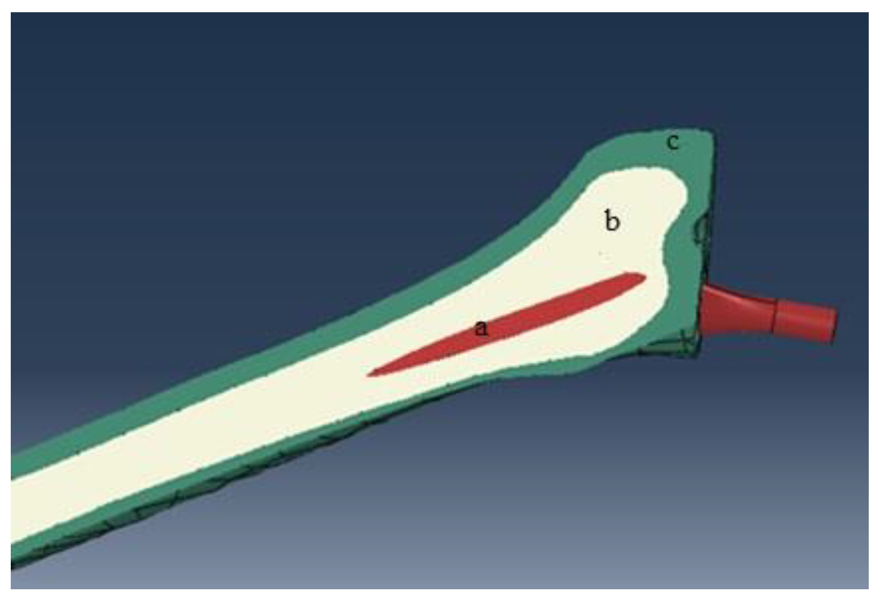
2.2. Design Methodology of the Femur Bone

A series of 2D computed tomography (CT) image slices of the femoral bone of a 28-year old male is used to rebuild the target area (see Figure 2). In this respect, a total of 251 images with 355 pixels × 251 pixels and a spatial resolution of 0.549 mm are utilized and exported to MIMICS® 15.0 software (Materialise, Leuven, Belgium). In the next step, the prosthesis is added to the femur bone in a computer-aided design (CAD) software (see Figure 1).

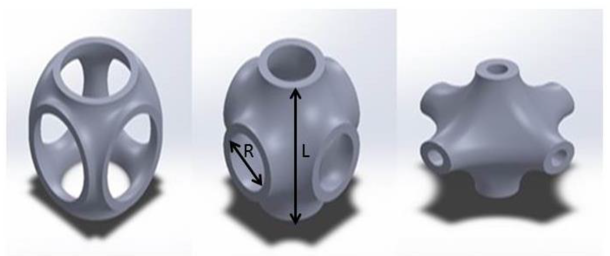
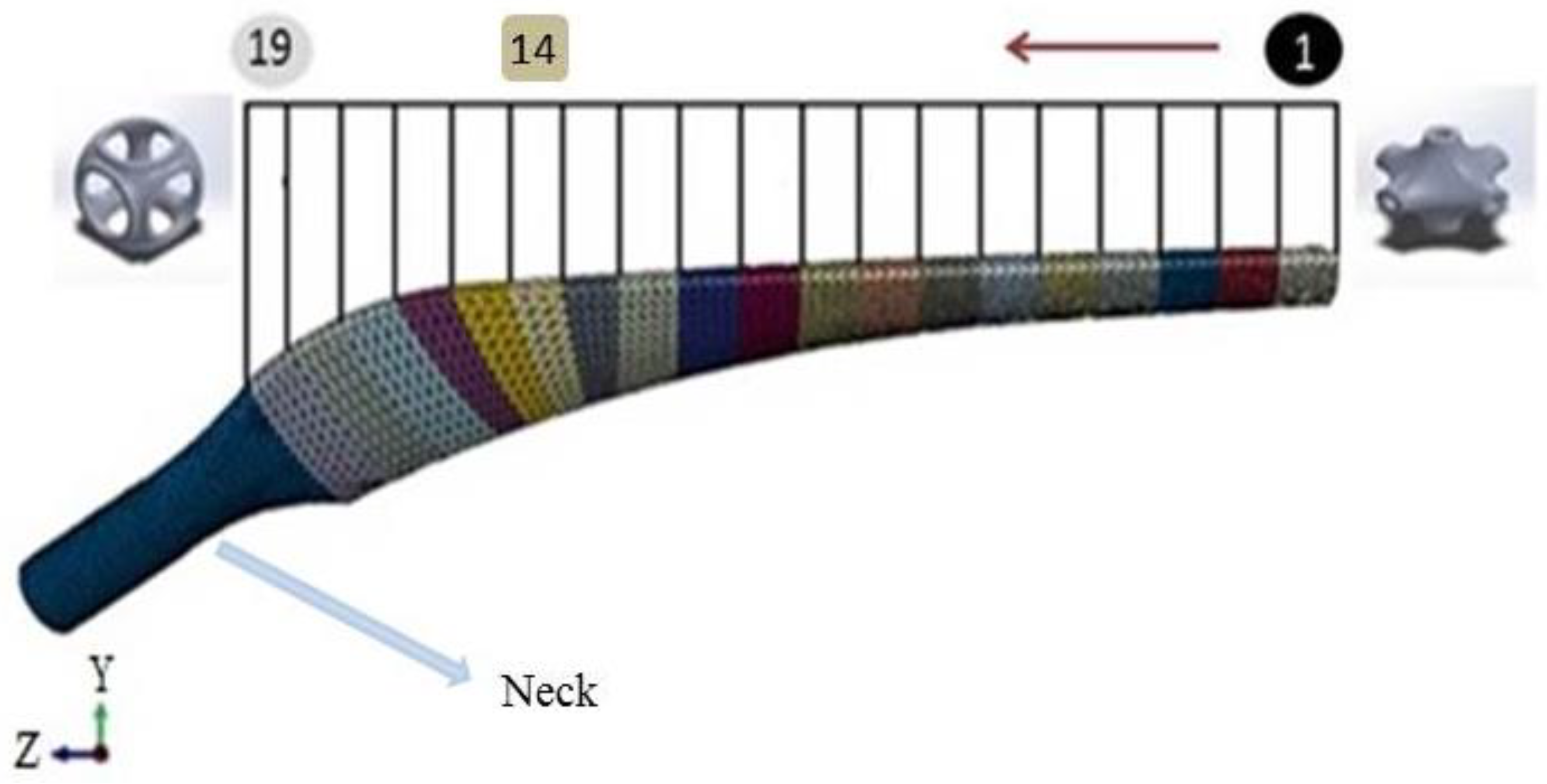
2.3. Designing of a Unit Cell and Implant

Minimal surfaces have many advantages that have been widely used in tissue engineering scaffolds. For example, they can facilitate cell migration and retain the high degree of structural stiffness [34,35]. Regarding that, the Schwarz Primitive (SP) triply periodic minimal surface (Figure 3) is opted for the base structure of the prosthesis. In Figure 3, R parameter represents the radius of the SP unit cell and L stands for the length of the unit cell. It should be noted that the prosthesis is divided into 19 separated layers (See Figure 4)—first fourteen layers have the same length (5 mm), but layers 15, 16, 17, 18, and 19 have shorter length (4 mm)—that are selected from Table 2; all of the different layers are constructed by an SP unit cell with various radius value, but identical thickness. Afterwards, the characteristics of the SP unit cell are assigned to the whole layer. As can be seen in Figure 4, the radius of each layer alters from layer number 1 to 19 to build the whole structure of the porous FG prosthesis; however, the neck of the implant has similar elasticity of the non-porous Ti.
In this study, three different morphologies for the FG architecture are investigated, as proposed in Table 3. The key point is the differences between increasing FG prosthesis (IFGP), decreasing FG prosthesis (DFGP), and neutral FG prosthesis (NFGP). In the IFGP, ratio of the radius to length of the unit cell (R/L) for the different layers is increased from layer number 1 to layer number 19; however, the pattern is reversed in DFGPs. The R/L of the NFGPs increases from layer number 1 to number 9 and then it decreases from number 9 to 19.

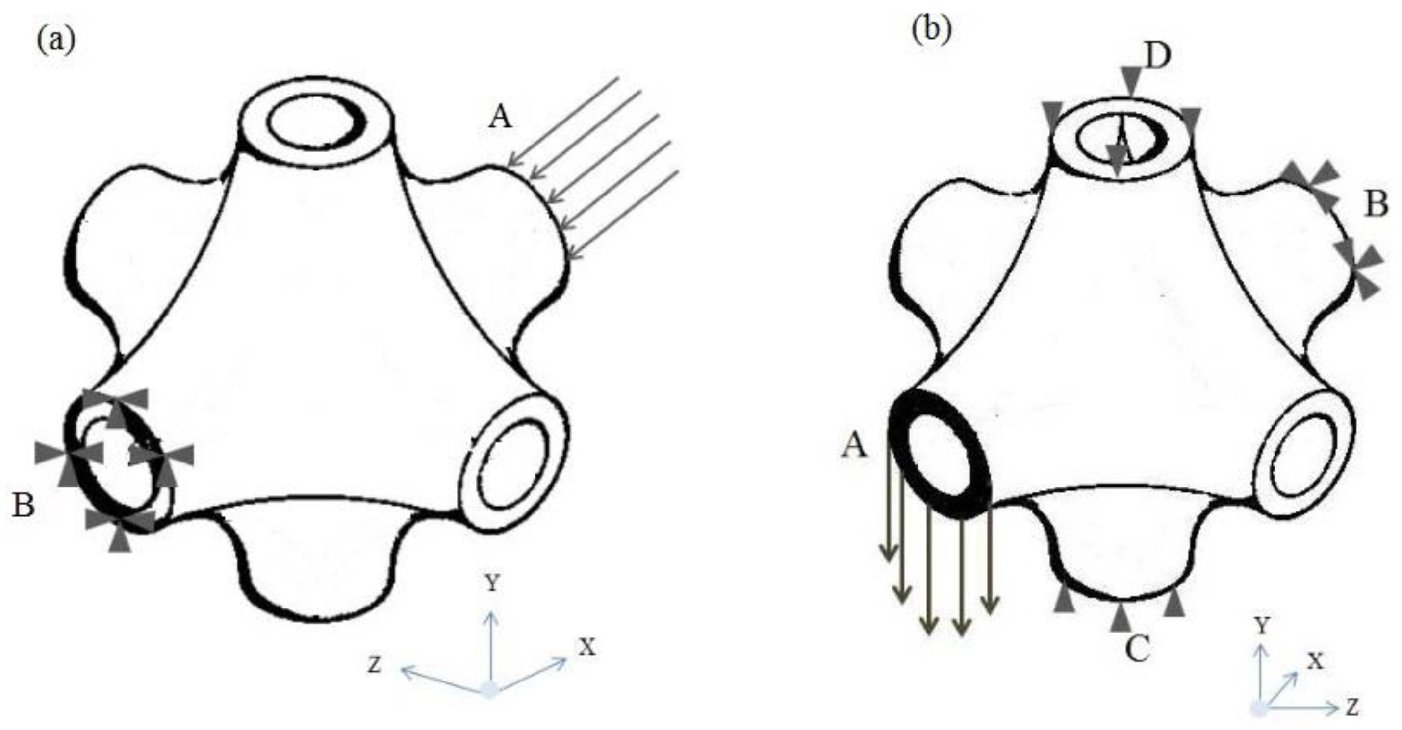
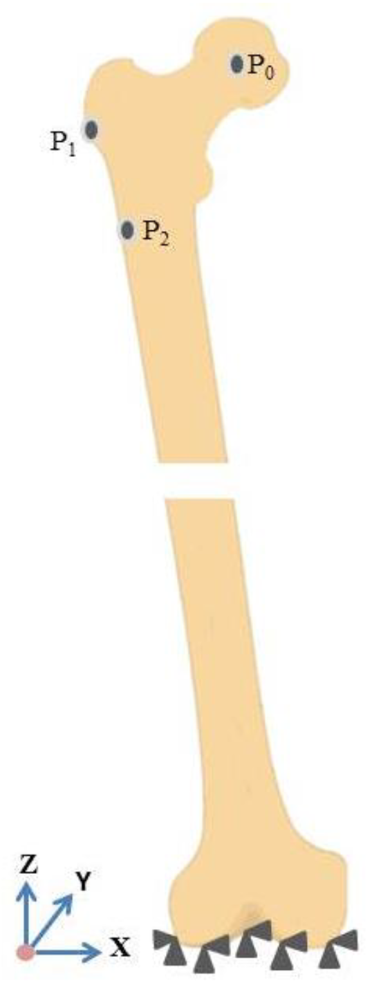
2.4. Finite Element Model and Boundary Conditions

As it has been mentioned in the previous section, the prosthesis consists of layers of different unit cells. Regarding that, the mechanical properties of the unit cells are computed by the FEM. Figure 5 shows the boundary conditions of the unit cell to calculate Young and shear moduli under different conditions. In Figure 5a, the compressive load is defined in the x direction, at the cross section of A, but the opposite cross section is totally fixed at any directions. In Figure 5b, two other cross sections (C and D) are prevented to move freely in the Y direction while applying a shear loading.
The femur bone made in the previous section is imported to an FEM-based software to investigate the mechanical properties of the prosthesis as well as the bone. Afterwards, regarding the physical elements and the complex shapes of the prosthesis and bone, a tetrahedral element possessing four nodes with three degrees of freedom at each node is selected. The optimized number of elements in each model is chosen by a sensitivity analysis conducted in this section. A statistical analysis is developed to simulate the loading condition on the implanted femur, and the highest contact force and the highest torsional moment in normal walking are employed too. Forces during normal walking are shown in Figure 6 and Table 4 [36].

3. Results and Discussion

In this study, a finite element investigation is performed to find optimum porous FG prosthesis with SP unit cells. Stress distribution of the uniform prosthesis (UP) for two paths (Figure 7) is compared with Ataollahi et al. [31] (see Figure 8). The results show a good agreement between results of the present model and those of Ataollahi et al. [31] verifying the FEM accuracy. The FEM model can reduce the cost of fabrication and precisely predict the mechanical properties of the prosthesis. This method can help researchers to find the best architecture of the prosthesis as well. In the following paragraphs, mechanical properties of different FG architecture will be investigated with the developed FEM. It is worth mentioning that there are many additive manufacturing works that investigated Ti lattice structures and the effects of pore size, boundary conditions, and process parameters [37,38]. However, utilizing an SP unit cell for femur prostheses is a novel work that does not have any counterpart. In this regard, the present study is comparable with some recent research works [31,39].

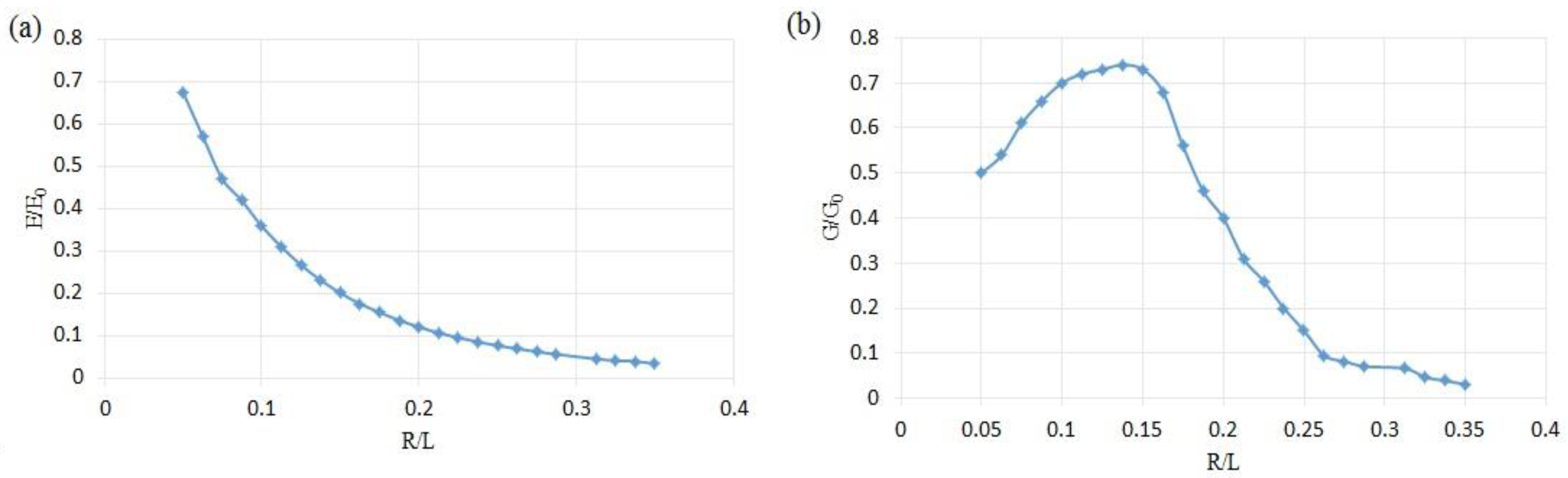
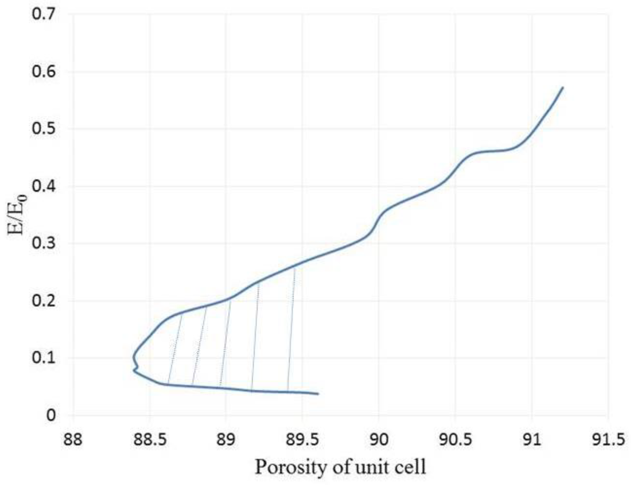
3.1. Mechanical Properties of the SP Unit Cells

The mechanical properties of the unit cells are investigated by the FEM software. Figure 9 illustrates the mechanical properties of 24 various unit cells. Figure 9 shows that increasing the radius of the SP unit cell can cause lower elastic modulus, but its slope decreases in a higher level of R/L. The normalized shear modulus has somewhat dissimilar to the elastic modulus. First, the value of the normalized shear modulus raises to R/L = 0.1373; afterwards, it decreases in higher values of the R/L. This unusual behavior can stem from the complex shape of the unit cell.
According to Figure 10, the SP unit cell can show same values of porosity in different points of modulus. This interesting characteristic can help a designer to select an appropriate quantity of the porosity regarding to the host tissue. This area has been hatched in Figure 10. Moreover, a higher value of the normalized elastic modulus can be reached by increasing the porosity. It illustrates the fact that the SP unit cell has an inherent potential to utilize in different organs with varying porosities. It should be noted that the non-dimensional results from the present elastic analysis, as shown in Figure 9, are independent of the material properties. Therefore, the trend of the diagrams in the following results will not change if other materials are selected. A similar conclusion was drawn in Ref. [39].

3.2. Investigation of the Bone and Prosthesis with Different Topologies

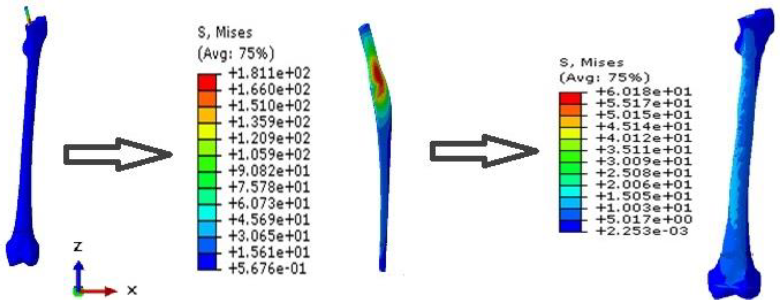
3.2.1. Uniform Prosthesis

After validation, the UP and the bone are investigated to better understand the stress distribution in both, and they will be compared with porous FG implants and their bones in the next sections (see Figure 11). Beside the stress distribution, two paths on the prosthesis are implemented to precisely detect the variation of the stress in the implant (see Figure 7).

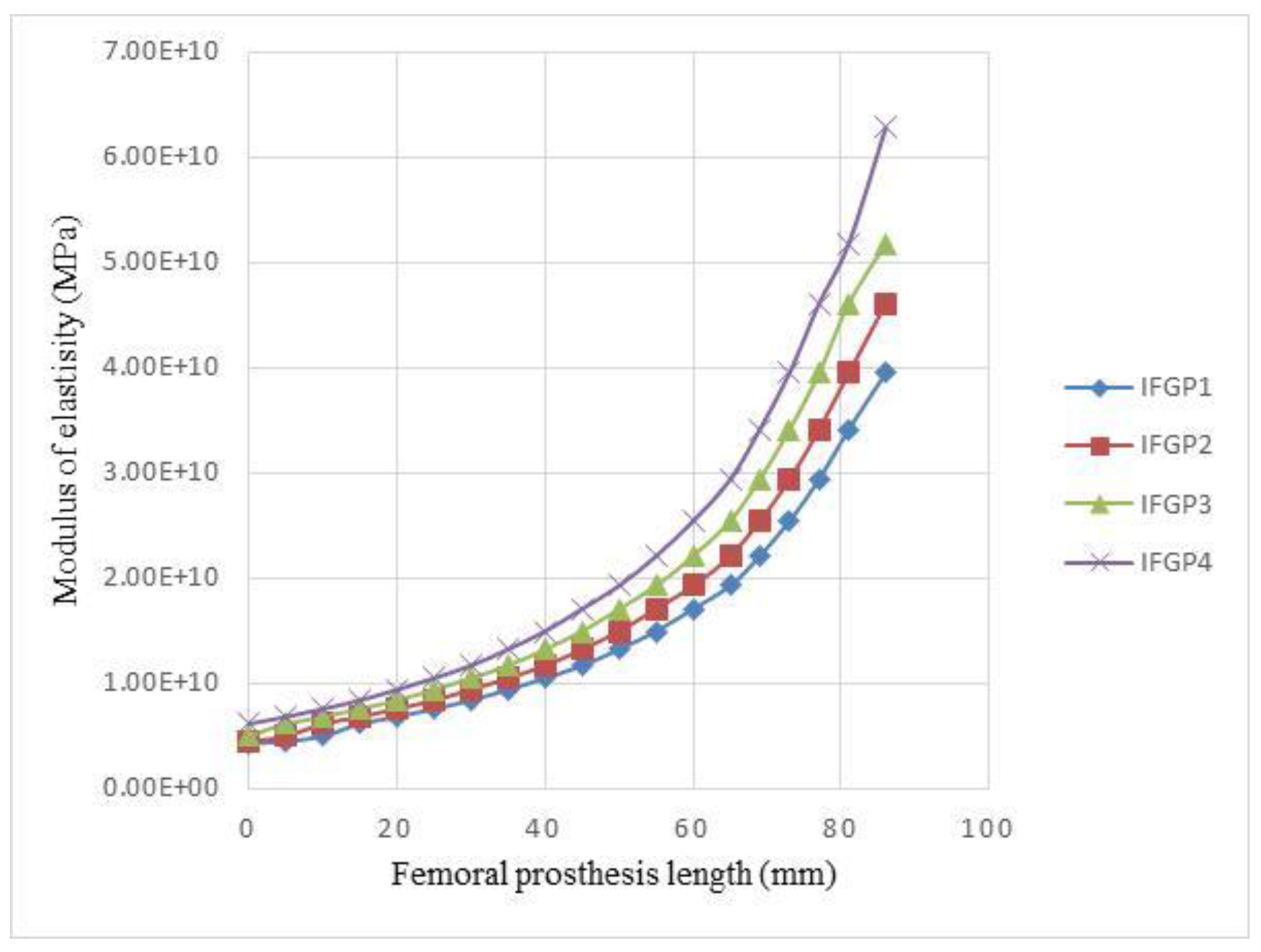
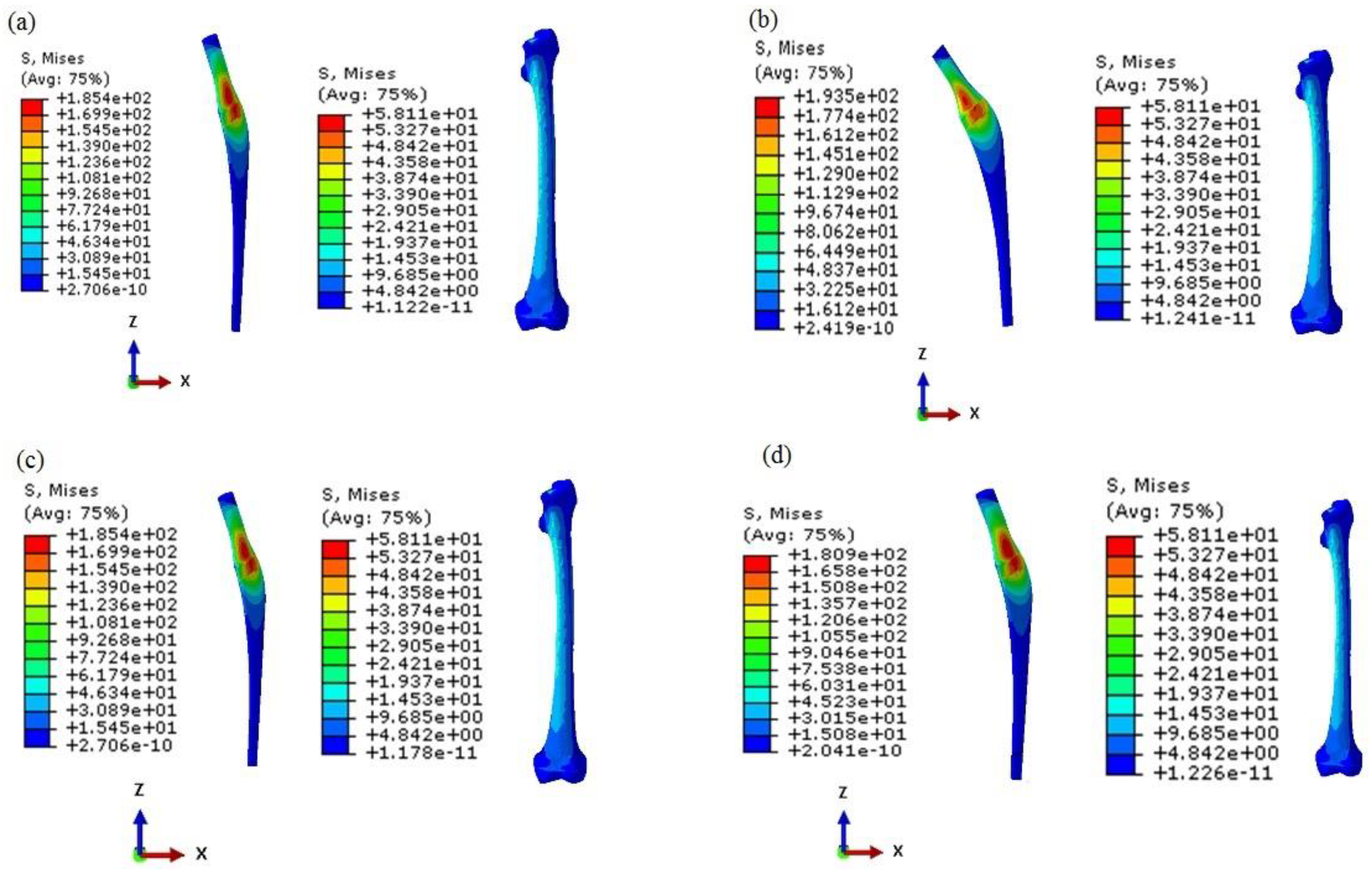
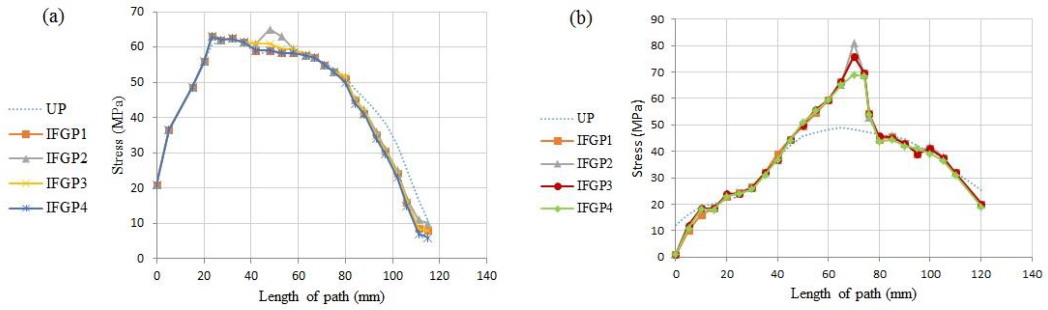
3.2.2. Increasing FG Prosthesis

As it has been mentioned before, in the IFGPs, the value of the R/L of the layers is increased from layer number 1 to number 19. This increasing topology is divided to four various increasing topologies, which are named IFGP1, IFGP2, IFGP3, and IFGP4. In these four increasing architectures, the IFGP4 has the lowest stress of the prosthesis, and provokes more stress on the bone. This can be the result of the reduction of the mismatch between bone and prosthesis, but in the IFGP1, IFGP2, and IFGP3, the lower elastic modulus leads to higher stress value, and increases mismatching between the prosthesis and bone. Figure 12 illustrates the fact that increasing the porosity in the neighborhood of the neck of the prosthesis can reduce the von Mises stress in the implant, but they make a stress concentration area in the proximal part of the bone (see Figure 13).
Figure 14 shows the stress distribution in two paths of P1 and P2. As can be seen in Figure 14a, the IFGPs and UP have roughly the same maximum stress value in path of P1, but, with moving away from the neck of the prosthesis in both directions, the UP illustrates higher values of stress in comparison to the IFGPs. The maximum stress in path P2 has the lower value in UP than IFGPs; however, they show higher values in other points (see Figure 14b). The bone maximum stress is about 60 MPa in UP and decreases to 50 MPa in IFGPs. This reducing stress in IFGPs lessens their chance to be selected as the best structure for the femoral prosthesis because it can stimulate the bone resorption [6].

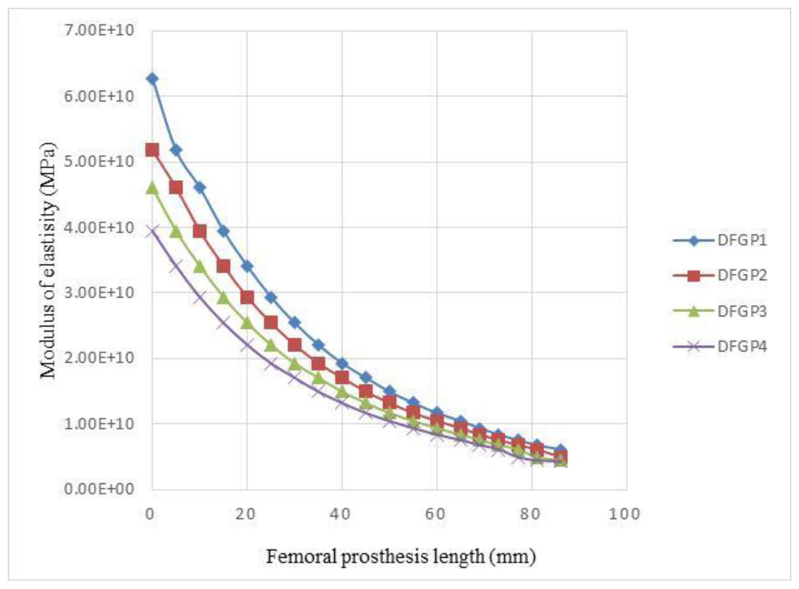
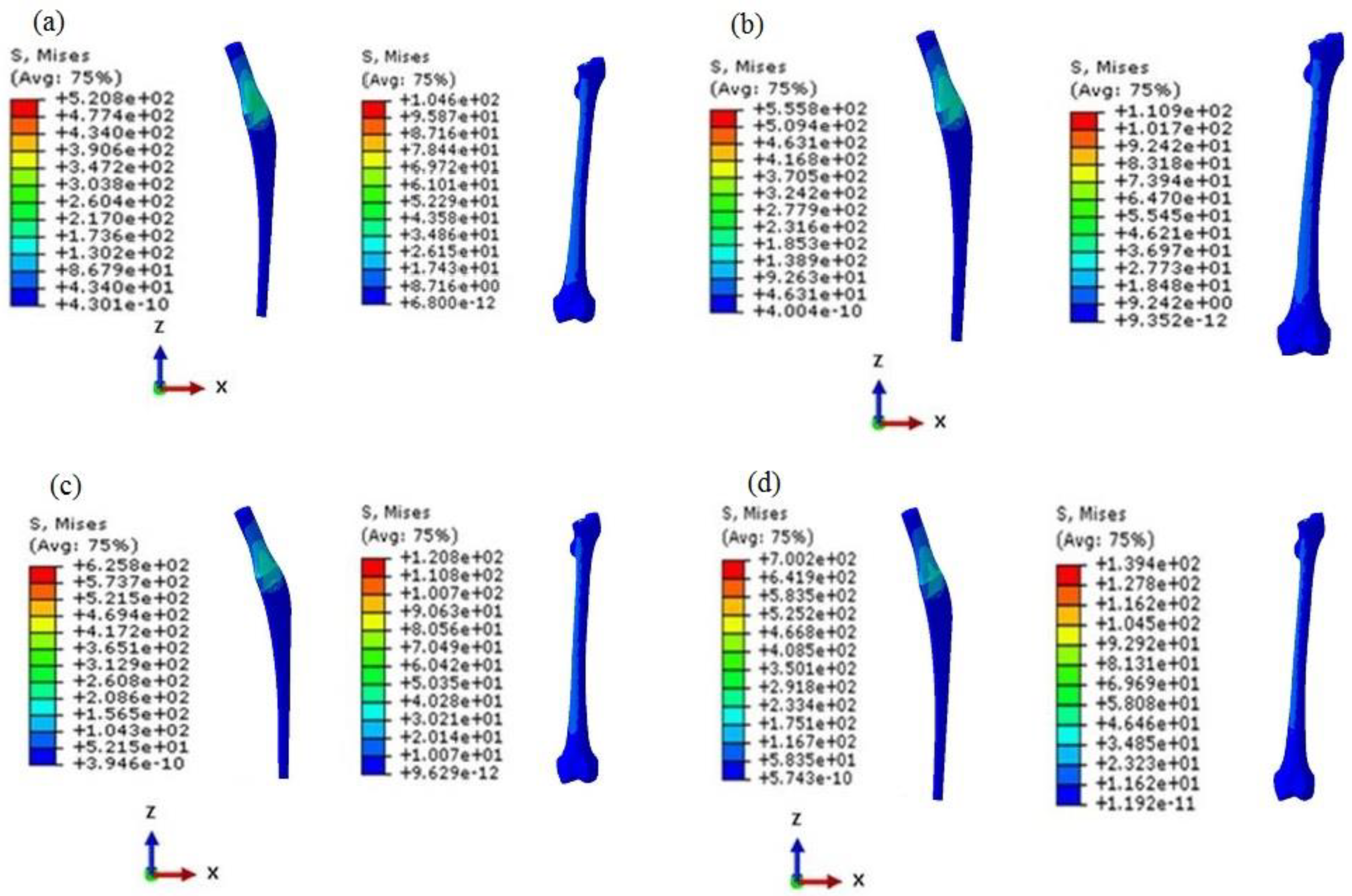
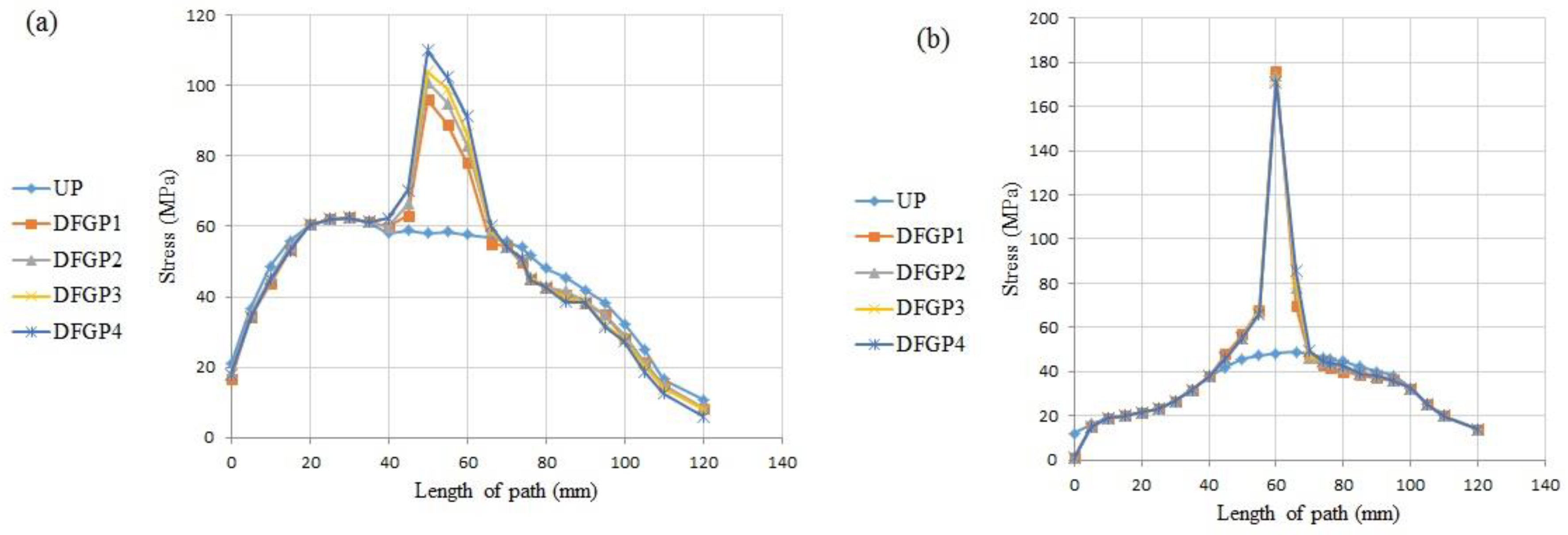
3.2.3. Decreasing FG Prosthesis

In the DFGPs, the value of R/L of the layers is decreased from layer number 1 to number 19. Four different scenarios are implemented for the DFGPs. Figure 15 illustrates the variations of the modulus of DFGPs. Figure 15, beside Figure 16, can help to find the best decreasing architecture for the prosthesis. The DFGP4 has the highest stress value, but has the lowest elastic modulus (see Figure 15). It shows that if the modulus of the elasticity is extremely lower than the elastic modulus of the neck, it will intensify the value of the maximum stress in the implant. Since the DFGP1 has a greater value of R/L, it can be more accurate than other DFGPs.
It is obvious that higher values of porosities of the layers can lead to higher stress values; therefore, the DFGPs tolerate higher stress than IFGPs, but the stress value of the bone can make DFGPs a better choice for the femoral implant. The maximum stresses in the bone reach to more than 100 MPa in the DFGPs. This rise in the stress value can elevate bone density and restrict the problems of the stress shielding behavior in a patient. The higher stress value of the implant can be compensated by choosing an appropriate material to endure loads in different conditions.
It can be interpreted from Figure 17 and according to the higher R/L values in proximity of the neck of the implant, that the stress value reaches to its peak in that area for the both paths, but the stress value of the DFGPs illustrates a lower quantity than the UP through the both paths. These lower and higher stress values in the bone make the DFGPs an eligible choice for the prosthesis. It can also reduce the mismatching between the stiffness of the prosthesis and the bone as a result of the reduction of the stress of the prosthesis. Moreover, decreasing the mismatching can remove the stress shielding and its negative influences.

3.2.4. Neutral FG Prosthesis

In the NFGPs, each R/L of the layers is increased from the layer number 1 to the middle of the prosthesis, but their value is decreased toward the neck and stem. The variation of elastic modulus of the layers is illustrated in Figure 18.
As demonstrated in Figure 19 and Figure 20, the NFGP cannot make any substantial changes in the prosthesis and bone, except that the stress values decrease in the stem part of the prosthesis. Actually, NFGPs have the same behavior as the UP under identical loading conditions.

4. Conclusions

The porous FG prosthesis was designed with three main architectures: IFGPs, DFGPs, and NFGP. It was found that the IFGPs result in better performances in the load bearing of the prosthesis in normal walking conditions, but they cannot elevate the stress that is imposed on the real scanned bone. The NFGP and UP totally have the same mechanical behavior in the prosthesis and the bone, but the DFGP results in an exceptional improvement at increasing the load on the bone. Their reduction of the elastic modulus of the base material of the prosthesis can diminish the mismatching between bone and prosthesis and prevent the stress shielding, which has many negative effects on a patient. Due to lack of any data on the porous FG prostheses with improved stress shielding, it is expected that the results supplied in the present work will be instrumental toward a reliable design of femoral prostheses under normal walking loading conditions.

Author Contributions

Conceptualization and Analysis, M.J.C.; Methodology and investigation, A.F., M.S., M.B., and S.M.R.; Project administration, A.F. and S.M.R.; Supervision and technical advice, A.F., M.B., S.M.R., and R.-A.J.-T.; Validation, M.J.C. and M.S.; Writing—original draft, M.S. and M.B.; Writing—review & editing, M.S. and M.B. All authors have read and agreed to the published version of the manuscript.

Funding

This research received no external funding.

Conflicts of Interest

The authors declare no conflict of interest.

References

  1. Tarlochan, F.; Mehboob, H.; Mehboob, A.; Chang, S.-H. Influence of functionally graded pores on bone ingrowth in cementless hip prosthesis: A finite element study using mechano-regulatory algorithm. Biomech. Model. Mechanobiol. 2017, 17, 701–716. [Google Scholar] [CrossRef] [PubMed]
  2. Alkhatib, S.E.; Tarlochan, F.; Mehboob, H.; Singh, R.; Kadirgama, K.; Harun, W.S.B.W. Finite element study of functionally graded porous femoral stems incorporating body-centered cubic structure. Artif. Organs 2019, 43, E152–E164. [Google Scholar] [CrossRef] [PubMed]
  3. Şensoy, A.T.; Çolak, M.; Kaymaz, I.; Findik, F. Optimal material selection for total hip implant: A finite element case study. Arab. J. Sci. Eng. 2019, 44, 10293–10301. [Google Scholar] [CrossRef]
  4. Hung, J.-P.; Bai, Y.-W.; Hung, C.-Q.; Lee, T.-E. Biomechanical performance of the cemented hip stem with different surface finish. Appl. Sci. 2019, 9, 4082. [Google Scholar] [CrossRef] [Green Version]
  5. Sola, A.; Bellucci, D.; Cannillo, V. Functionally graded materials for orthopedic applications–an update on design and manufacturing. Biotechnol. Adv. 2016, 34, 504–531. [Google Scholar] [CrossRef] [PubMed]
  6. Arabnejad, S.; Johnston, B.; Tanzer, M.; Pasini, D. Fully porous 3D printed titanium femoral stem to reduce stress-shielding following total hip arthroplasty. J. Orthop. Res. 2017, 35, 1774–1783. [Google Scholar] [CrossRef]
  7. Castro, A.; Completo, A.; Simões, J.; Flores, P. Modelling and simulation of alternative designs for the femur–implant interface of Journey patellofemoral prosthesis. Proc. Inst. Mech. Eng. Part L J. Mater. Des. Appl. 2019, 233, 1619–1628. [Google Scholar] [CrossRef]
  8. Cheruvu, B.; Venkatarayappa, I.; Goswami, T. Stress shielding in cemented hip implants assessed from computed tomography. Biomed. J. Sci. Tech. Res. 2019, 18, 13637–13641. [Google Scholar]
  9. Bougherara, H.; Bureau, M.; Campbell, M.; Vadean, A.; Yahia, L.H. Design of a biomimetic polymer-composite hip prosthesis. J. Biomed. Mater. Res. Part A 2007, 82, 27–40. [Google Scholar] [CrossRef] [Green Version]
  10. Rezaei, F.; Hassani, K.; Solhjoei, N.; Karimi, A. Carbon/PEEK composite materials as an alternative for stainless steel/titanium hip prosthesis: A finite element study. Australas. Phys. Eng. Sci. Med. 2015, 38, 569–580. [Google Scholar] [CrossRef]
  11. Naidubabu, Y.; Mohana Rao, G.; Rajasekhar, K.; Ratna Sunil, B. Design and simulation of polymethyl methacrylate-titanium composite bone fixing plates using finite element analysis: Optimizing the composition to minimize the stress shielding effect. Proc. Inst. Mech. Eng. Part C J. Mech. Eng. Sci. 2017, 231, 4402–4412. [Google Scholar] [CrossRef]
  12. Enab, T. Behavior of FGM-coated, HA-coated and uncoated femoral prostheses with different geometrical configurations. Int. J. Mech. Mechatron. Eng. 2016, 16, 198949870. [Google Scholar]
  13. Oshkour, A.; Osman, N.A.; Bayat, M.; Afshar, R.; Berto, F. Three-dimensional finite element analyses of functionally graded femoral prostheses with different geometrical configurations. Mater. Des. 2014, 56, 998–1008. [Google Scholar] [CrossRef]
  14. Shirzad, M.; Fathi, A.; Rabiee, S.M.; Ghaffari, S.; Zabihi-Neishabouri, E. Three-dimensional printing of truss-like structure for use in scaffold: Experimental, numerical, and analytical analyses. Proc. Inst. Mech. Eng. Part C J. Mech. Eng. Sci. 2020. [Google Scholar] [CrossRef]
  15. Pompe, W.; Worch, H.; Epple, M.; Friess, W.; Gelinsky, M.; Greil, P.; Hempel, U.; Scharnweber, D.; Schulte, K. Functionally graded materials for biomedical applications. Mater. Sci. Eng. A 2003, 362, 40–60. [Google Scholar] [CrossRef]
  16. Hambli, R.; Hattab, N. Application of neural network and finite element method for multiscale prediction of bone fatigue crack growth in cancellous bone. In Multiscale Computer Modeling in Biomechanics and Biomedical Engineering; Springer: Berlin/Heidelberg, Germany, 2013; pp. 3–30. [Google Scholar]
  17. Mehrali, M.; Shirazi, F.S.; Mehrali, M.; Metselaar, H.S.C.; Kadri, N.A.B.; Osman, N.A.A. Dental implants from functionally graded materials. J. Biomed. Mater. Res. Part A 2013, 101, 3046–3057. [Google Scholar] [CrossRef] [PubMed]
  18. Mahmoudi, M.; Saidi, A.R.; Hashemipour, M.A.; Amini, P. The use of functionally graded dental crowns to improve biocompatibility: A finite element analysis. Comput. Methods Biomech. Biomed. Eng. 2018, 21, 161–168. [Google Scholar] [CrossRef]
  19. Khoo, W.; Chung, S.M.; Lim, S.C.; Low, C.Y.; Shapiro, J.M.; Koh, C.T. Fracture behavior of multilayer fibrous scaffolds featuring microstructural gradients. Mater. Des. 2019, 184, 108184. [Google Scholar] [CrossRef]
  20. Loh, G.H.; Pei, E.; Harrison, D.; Monzon, M.D. An overview of functionally graded additive manufacturing. Addit. Manuf. 2018, 23, 34–44. [Google Scholar] [CrossRef] [Green Version]
  21. Yang, Q.; Cao, H.; Tang, Y.; Yang, B. Out-of-plane bending of functionally graded thin plates with a circular hole. Appl. Sci. 2020, 10, 2231. [Google Scholar] [CrossRef] [Green Version]
  22. Zhang, X.-Y.; Yan, X.-C.; Fang, G.; Liu, M. Biomechanical influence of structural variation strategies on functionally graded scaffolds constructed with triply periodic minimal surface. Addit. Manuf. 2020, 32, 101015. [Google Scholar] [CrossRef]
  23. Zhao, M.; Liu, F.; Fu, G.; Zhang, D.Z.; Zhang, T.; Zhou, H. Improved mechanical properties and energy absorption of BCC lattice structures with triply periodic minimal surfaces fabricated by SLM. Materials 2018, 11, 2411. [Google Scholar] [CrossRef] [PubMed] [Green Version]
  24. Rahmani, R.; Antonov, M.; Kollo, L.; Holovenko, Y.; Prashanth, K.G. Mechanical behavior of ti6Al4V scaffolds filled with caSiO3 for implant applications. Appl. Sci. 2019, 9, 3844. [Google Scholar] [CrossRef] [Green Version]
  25. Kluess, D.; Soodmand, E.; Lorenz, A.; Pahr, D.; Schwarze, M.; Cichon, R.; Varady, P.A.; Herrmann, S.; Buchmeier, B.; Schröder, C.; et al. A round-robin finite element analysis of human femur mechanics between seven participating laboratories with experimental validation. Comput. Methods Biomech. Biomed. Eng. 2019, 22, 1020–1031. [Google Scholar] [CrossRef]
  26. Moita, J.S.; Correia, V.F.; Soares, C.M.M.; Herskovits, J. Higher-order finite element models for the static linear and nonlinear behaviour of functionally graded material plate-shell structures. Compos. Struct. 2019, 212, 465–475. [Google Scholar] [CrossRef]
  27. Colic, K.; Sedmak, A.; Grbovic, A.; Tatic, U.; Sedmak, S.; Djordjevic, B. Finite element modeling of hip implant static loading. Procedia Eng. 2016, 149, 257–262. [Google Scholar] [CrossRef] [Green Version]
  28. Pandithevan, P.; Prasannavenkadesan, V. Investigation on the influence of hip joint loading in peak stress during various activities. In Proceedings of the 2nd International Conference on Computer Vision & Image Processing, Jaipur, India, 27–29 September 2018; pp. 249–254. [Google Scholar]
  29. Andreaus, U.A.; Colloca, M.; Toscano, A. Mechanical behaviour of a prosthesized human femur: A comparative analysis between walking and stair climbing by using the finite element method. Biophys. Bioeng. Lett. 2008, 1, 2774. [Google Scholar]
  30. Reggiani, B.; Cristofolini, L.; Varini, E.; Viceconti, M. Predicting the subject-specific primary stability of cementless implants during pre-operative planning: Preliminary validation of subject-specific finite-element models. J. Biomech. 2007, 40, 2552–2558. [Google Scholar] [CrossRef]
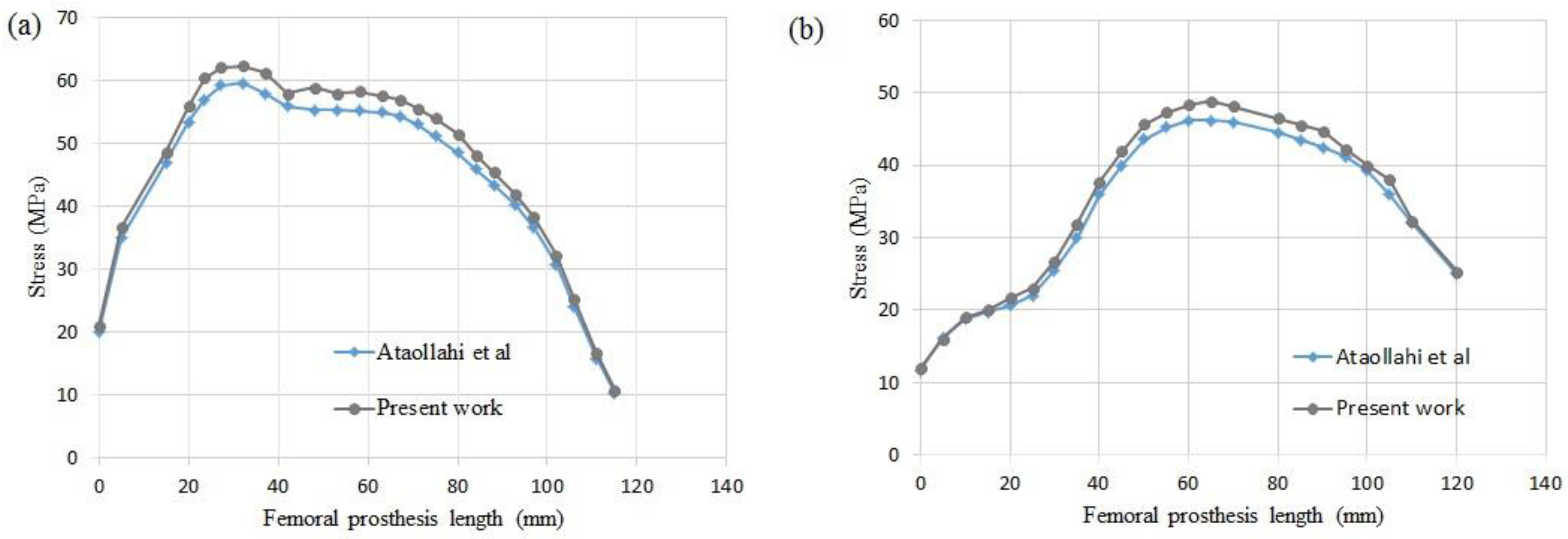
  31. Ataollahi Oshkour, A.; Talebi, H.; Shirazi, S.; Farid, S.; Bayat, M.; Yau, Y.H.; Tarlochan, F.; Osman, A.; Azuan, N. Comparison of various functionally graded femoral prostheses by finite element analysis. Sci. World J. 2014, 807621. [Google Scholar] [CrossRef]
  32. Ridzwan, M.I.Z.; Shuib, S.; Hassan, A.Y.; Shokri, A.A.; Ibrahim, M.M. Problem of stress shielding and improvement to the hip implant designs: A review. J. Med. Sci. 2007, 7, 460–467. [Google Scholar]
  33. Zhu, S.; Wang, X.; Qin, F.; Inoue, A. A new Ti-based bulk glassy alloy with potential for biomedical application. Mater. Sci. Eng. A 2007, 459, 233–237. [Google Scholar] [CrossRef]
  34. Kapfer, S.C.; Hyde, S.T.; Mecke, K.; Arns, C.H.; Schröder-Turk, G.E. Minimal surface scaffold designs for tissue engineering. Biomaterials 2011, 32, 6875–6882. [Google Scholar] [CrossRef] [PubMed]
  35. Zhu, L.-Y.; Cheng, M.; Sun, W.-C.; Yang, J.-Q.; Li, L.; Jiang, Q. Influence of deformed primitive architecture on mechanical behavior of artificial porous meniscus. Mater. Des. 2020, 186, 108303. [Google Scholar] [CrossRef]
  36. Heller, M.O.; Bergmann, G.; Kassi, J.-P.; Claes, L.; Haas, N.P.; Duda, G.N. Determination of muscle loading at the hip joint for use in pre-clinical testing. J. Biomech. 2005, 38, 1155–1163. [Google Scholar] [CrossRef] [PubMed]
  37. Asadi-Eydivand, M.; Solati-Hashjin, M.; Fathi, A.; Padashi, M.; Osman, N.A.A. Optimal design of a 3D-printed scaffold using intelligent evolutionary algorithms. Appl. Soft Comput. 2016, 39, 36–47. [Google Scholar] [CrossRef]
  38. Torres-Sanchez, C.; McLaughlin, J.; Fotticchia, A. Porosity and pore size effect on the properties of sintered Ti35Nb4Sn alloy scaffolds and their suitability for tissue engineering applications. J. Alloys Compd. 2018, 731, 189–199. [Google Scholar] [CrossRef] [Green Version]
  39. Almeida, H.A.; Bártolo, P.J. Design of tissue engineering scaffolds based on hyperbolic surfaces: Structural numerical evaluation. Med. Eng. Phys. 2014, 36, 1033–1040. [Google Scholar] [CrossRef]
Figure 1. The structure of the bone and implant: (a) implant, (b) cancellous bone, and (c) cortical bone.
Designs 04 00012 g001
Figure 2. Full femur scanned images turned to the CAD file.
Designs 04 00012 g002
Figure 3. The SP triply periodic minimal surface with different radius.
Designs 04 00012 g003
Figure 4. The gradient design of the prosthesis with nineteen different layers.
Designs 04 00012 g004
Figure 5. Boundary conditions of the SP unit cell: (a) compressive boundary condition, (b) shear boundary condition.
Designs 04 00012 g005
Figure 6. Boundary conditions of the femur bone.
Designs 04 00012 g006
Figure 7. Two paths toward the longitudinal direction of the prosthesis.
Designs 04 00012 g007
Figure 8. Validation of the present work with Ataollahi et al. for (a) path P1, (b) path P2.
Designs 04 00012 g008
Figure 9. The normalized modulus of SP unit cells at different R/L: (a) normalized elastic modulus, (b) normalized shear modulus.
Designs 04 00012 g009
Figure 10. The normalized elastic modulus versus the SP unit cell’s porosity.
Designs 04 00012 g010
Figure 11. Stress distribution of the UP and its bone.
Designs 04 00012 g011
Figure 12. Variations of the elastic modulus of IFGPs with different architectures.
Designs 04 00012 g012
Figure 13. The von Mises stress distribution of the prosthesis and bone in the IFGPs: (a) IFGP1, (b) IFGP2, (c) IFGP3, (d) IFGP4.
Designs 04 00012 g013
Figure 14. The stress distribution in two paths in the IFGPs: (a) path P1, (b) path P2.
Designs 04 00012 g014
Figure 15. Variations of the elastic modulus of DFGPs with different architectures.
Designs 04 00012 g015
Figure 16. The von Mises stress distribution of prosthesis and bone in the DFGPs: (a) DFGP1, (b) DFGP2, (c) DFGP3, (d) DFGP4.
Designs 04 00012 g016
Figure 17. The stress distribution in two paths in the DFGPs: (a) Path P1, (b) Path P2.
Designs 04 00012 g017
Figure 18. Variations of the elastic modulus of NFGP.
Designs 04 00012 g018
Figure 19. The von Mises stress distribution of prosthesis and bone in the NFGP.
Designs 04 00012 g019
Figure 20. The stress distribution in two paths in the NFGP: (a) path P1, (b) path P2.
Designs 04 00012 g020
Table 1. The mechanical properties of the cortical and cancellous bone.
MaterialPlaneModulus of Elasticity (GPa)Modulus of Rigidity (GPa)Poisson’s Ratio
xx11.53.60.51
Cortical boneyy11.53.30.31
zz173.30.31
Cancellous bone-2.13-0.3
Table 2. Physical characteristics and mechanical properties of the different SPs.
Unit Cell NumberR/LPorosity (%)Surface Area of the Reaction Force (mm2)Stress (MPa)Unit Cell NumberR/LPorosity (%)Surface Area of the Reaction Force (mm2)Stress (MPa)
10.0591.82.361350.5130.199888.3927.062401.6
20.062591.392.751143.9140.212388.3327.452134.4
30.074890.953.14942150.224888.3067.851901.9
40.087390.5353.53837.79160.237388.3178.24170.21
50.099890.1513.92719.6170.249888.3638.63152.71
60.112389.8034.31620.3180.262388.4449.03137.08
70.124889.4924.71534.16190.274888.5599.42123.34
80.137389.2175.1463.15200.287388.719.81111.04
90.149888.9775.49401.54210.312389.13110.689.89
100.162388.7755.89350.98220.324889.67710.9980.89
110.174888.6126.2311.16230.337389.911.3878.12
120.187388.4826.672712.7240.349890.0411.7765.47
Table 3. The FG prosthesis architecture.
TopologyIFGPDFGPNFGP
Range of R/LIFGP1IFGP2IFGP3IFGP4DFGP1DFGP2DFGP3DFGP4NFGP
Upper0.27480.28730.31230.32480.27480.28730.31230.32480.2748
Lower0.050.06250.07480.08730.050.06250.07480.08730.05
Table 4. The maximum contact force of normal walking.
Force (N)DirectionActs at Point
xyz
Hip contact−378−229.6−1604.4P0
Abductor40630.1605.5P1
Tensor fascia lata, proximal part50.481.292.4P1
Tensor fascia lata, distal part−3.5−4.9−133P1
Vastus lateralis−6.3129.5−650.3P2

