1. Introduction
Safety-critical CPS demand assures services under all considered load and fault assumptions in order to minimize the risk for people, property and the environment. Therefore, electronic systems are subject to domain-specific certification processes (e.g., ISO26262, IEC61508, and DO178/254), which provide documented evidence and safety arguments.
Time-triggered systems facilitate the establishment of safety arguments and have thus become prevalent in many safety-critical applications. Schedule tables are defined at development time and determine global points in time for the initiation of activities, such as sending a message or starting a computation. Major benefits are temporal predictability, temporal composability and support for fault containment [
1]. Time-triggered systems simplify the system design and reduce the probability of design faults by offering implicit synchronization, implicit flow control and transparent fault tolerance. By deriving all control signals from the global time base, there is no control flow between application components, which can be independently developed and seamlessly integrated. Furthermore, a priori knowledge about the permitted temporal behavior can be used by network guardians or operating systems for isolating faulty messages or tasks, thereby preventing fault propagation via shared resources. This fault containment is a prerequisite for active redundancy as well as modular and incremental certification [
2,
3].
Time-triggered operation has been realized at different levels. Many safety-critical distributed systems are deployed with time-triggered communication networks such as Time-Triggered Ethernet (TTE), Time-Triggered Protocol (TTP), FlexRay and IEEE 802.1Qbv/TSN [
1,
4]. Time-triggered operating systems and hypervisors (e.g., ARINC653 [
5]) adopt scheduling tables for cyclic time-based executions of partitions to virtualize the processor. Time-triggered multi-core architectures (e.g., TTMPSoC [
6] and COMPSoC [
7]) use time-triggered Network-on-Chips (NoCs) in analogy to the time-triggered networks in distributed systems.
At the same time, adaptive system behaviors upon relevant events are desirable to improve energy efficiency, reliability and context awareness. For example, execution slack enables energy management, such as voltage/frequency scaling and clock gating. Information about faults can serve for fault recovery by redistributing application services on the system’s remaining resources. Changing environmental conditions or operational modes may demand for different application services (e.g., take-off vs. in-flight of an airplane).
Time-triggered systems can support this adaptation through the deployment of precomputed schedules for the relevant events [
8]. However, the major challenge is preserving the properties of time-triggered systems, such as temporal predictability, fault containment and implicit synchronization. Therefore, all building blocks must consistently switch between schedules. This requires system-wide consistent information about the context events determining the adaptation. In addition, the adaptation must work correctly in the presence of faults to prevent the introduction of vulnerabilities. Further requirements are bounded times of adaptation for fault recovery and the efficient storage of large numbers of schedules.
This paper introduces the Adaptive Time-triggered Multi-core Architecture (ATMA) that fulfills these requirements. The architecture establishes a system-wide consistent agreement on context events as well as robust and efficient switching between schedules.
Prior work has addressed computing schedule graphs for time-triggered systems (e.g., [
9,
10]). However, the combination of agreement, adaptation and meta-scheduling as part of a time-triggered multi-core architecture supporting implicit synchronization, fault containment and timeliness is an open research problem. Furthermore, the presented techniques for minimizing the overhead of adaptation (e.g., difference encoding of multi-schedule graphs, and adjustable reconvergence horizons for events) enable scalability and the deployment in resource-constrained applications.
The paper builds on previous work of the authors where a non-adaptive time-triggered multi-core architecture [
6] was introduced as well as individual components for agreement [
11] and adaptation [
12]. This paper introduces the overall architecture of an adaptive time-triggered multi-core architecture along with the interplay of agreement, adaptation and meta scheduling. The paper provides experimental results for the overall architecture and shows the suitability for improved energy efficiency and fault tolerance. In addition, the paper introduces adaptation concepts for time-triggered systems and describes the services and system properties, which are essential to preserve implicit synchronization, temporal predictability and avoidance of resource conflicts.
The remainder of the paper is structured as follows.
Section 2 analyzes the challenges and requirements for adaptation in time-triggered systems. The ATMA is the focus of
Section 3.
Section 4 describes the computation of multiple schedules, each serving for certain context events.
Section 5 introduces agreement services, which establish chip-wide consistent context information. The context information is used for adaptive communication in
Section 6.
Section 7 presents example scenarios and the experimental evaluation.
2. Adaptation in Time-Triggered Systems
Adaptation in time-triggered systems is motivated by higher energy efficiency, fault recovery and the adjustment to changing environmental conditions. However, the fundamental properties and strengths of time-triggered systems must be preserved in order to obtain suitability for safety-critical systems.
2.1. Properties of Time-Triggered Systems
Time-triggered systems exhibit specific properties, which result from the dispatching of cyclic activities driven by the global time base and precomputed schedule tables:
Avoidance of resource contention without dynamic resource arbitration: The precomputed schedules ensure that each resource is used by at most one user at any particular point in time. Thus, dynamic resource arbitration is not necessary.
Implicit synchronization: The precomputed schedules satisfy synchronization requirements based on the global time including precedence constraints and avoidance of race conditions.
Guaranteeing of timing constraints: The computation of schedules at development time ensures that deadlines are met without further runtime efforts beyond time-triggered dispatching.
Implicit flow control: The computation of schedules considers the receivers’ ability for handling received messages. Therefore, an overload of receivers is prevented without acknowledgments or flow control protocols.
Fault containment: A priori knowledge about the permitted behavior of components allows to block faulty messages, thereby preventing fault propagation via shared resources.
These properties are essential characteristics of a time-triggered system and must be preserved despite adaptation. Henceforth, we call these properties the ATMA properties. In the ATMA, these properties are determined by the schedules computed offline, as well as the correct dispatching and schedule switching at runtime.
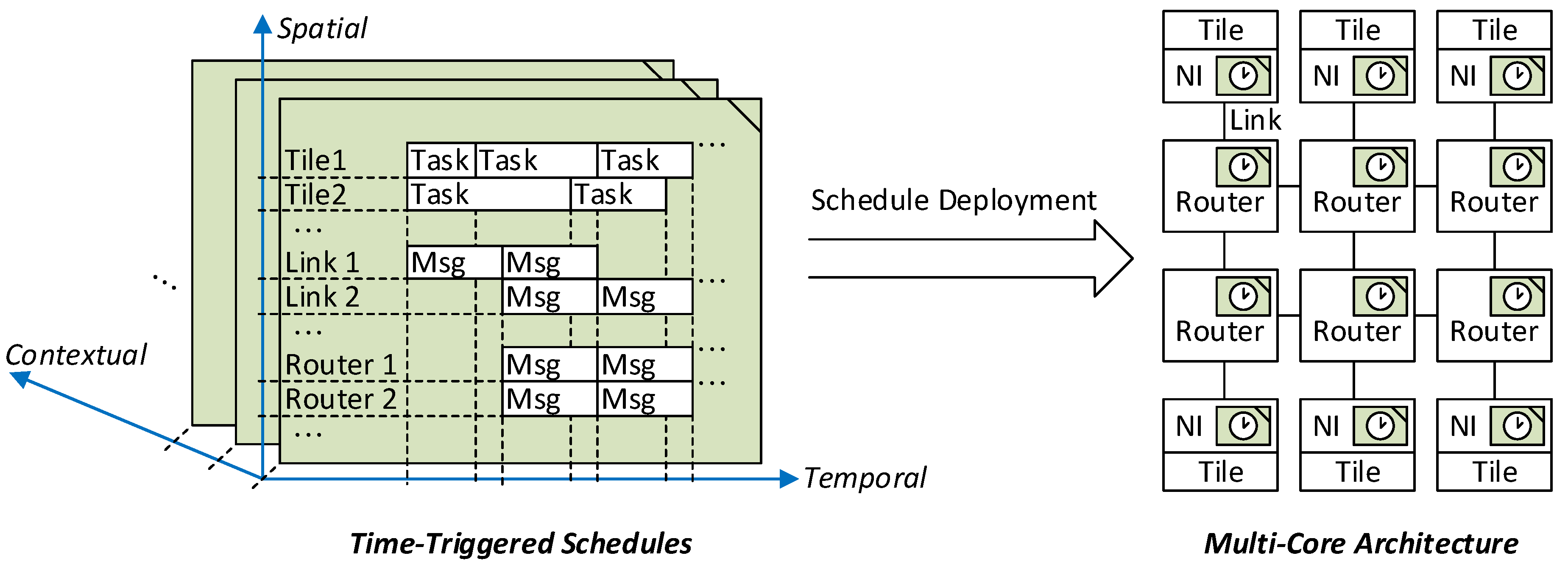
In order to realize these properties, a schedule encompasses three dimensions as depicted in
Figure 1. The schedule defines in the temporal dimension when activities need to be dispatched with respect to the global time base. In the spatial dimension, the schedule defines the triggers for the different resources of the multi-core architecture such as Network Interfaces (NIs), routers and communication links. The third dimension corresponds to the contextual dimension, where different plans for the context events are distinguished. Overall, the time-triggered schedule thus defines what activities shall be dispatched for each resource and each relevant context event at which global points in time.
In general, the schedules must be deployed in multiple building blocks of the architecture as depicted on the right hand side of
Figure 1. Each schedule is fragmented along the spatial dimension and the resulting parts are assigned to the resources. NIs are the target in case of NoCs with source-based routing and routers in case of distributed routing. Furthermore, in order to acquire the ATMA properties, consistency of the schedules in temporal and spatial dimension is essential. For instance, messages must be passed without resource conflicts along the communication links in the spatial and temporal dimensions, while satisfying the deadlines and precedence constraints.
2.2. Need for Adaptation
In the following, the motivation for adaptation in time-triggered systems is detailed.
2.2.1. Energy Efficiency
Energy efficiency is relevant for many safety-critical systems. Examples are battery-operated devices (e.g., medical equipment, wireless sensors for railway systems [
13]) and systems with thermal constraints (e.g., avionics [
14]). While techniques for energy management such as Dynamic Voltage and Frequency Scaling (DVFS) and clock gating are common in many application areas (e.g., consumer electronics), the applicability for safety-critical systems is often limited. Certification and the computation of Worst Case Execution Times (WCETs) for multi-core processors is challenging by itself [
15] and further complicated by energy management. If dynamic slack of one task is exploited for dynamic modifications of frequencies or clock gating, then unpredictable timing effects and fault propagation can occur for other tasks due to shared resources such as caches and I/O.
In safety-critical systems, we can distinguish between two types of energy sensitivity with respect to safety certification:
Energy efficiency without detrimental effects on safety. Energy management is desirable for availability or economic reasons (e.g., energy cost) but not required for safety. For example, a safe state is reached when energy resources are depleted. Therefore, energy management must not affect the system’s safety functions.
Energy efficiency as part of the safety argument. Energy efficiency is part of the safety argument, e.g., because battery capacity must suffice for the mission time or thermal constraints must be satisfied under all load and fault conditions.
Both types can be effectively supported by adaptable time-triggered systems. Adaptable time-triggered systems promise to improve energy efficiency without detrimental effects on temporal predictability and fault containment. Different schedules serve for potential system conditions like various dynamic-slack values. Each schedule can be analyzed in isolation as in a fully static time-triggered system.
2.2.2. Lower Cost for Fault-Tolerance by Fault Recovery and Reduced Redundancy Degrees
In safety-critical applications, an embedded computer system has to provide its services with a dependability that is better than the dependability of any of its constituent components. Considering the failure-rate data of available electronic components, the required level of dependability can only be achieved if the system supports fault tolerance.
N-modular redundancy is a widely deployed technique, where the assumptions concerning failure modes and failure rates determine the necessary replication degrees. For example, a triple-triple redundant primary fight computer is deployed in the Boeing 777 aircraft [
16]. However, emerging application areas with safety-critical embedded systems and stringent cost-pressure for electronic equipment cannot afford the high cost associated with excessive replication. For example, fully autonomous vehicles depend on ASIL-D [
17] functions for environmental sensing and vehicle control. At the same time, the extreme cost pressure of the automotive industry precludes the massive deployment of redundant components.
Fault recovery is a viable alternative by switching to configurations that do not use failed resources. The following fault-recovery approaches can be deployed to achieve fault-tolerance:
Modifying allocation of services to resources. The system design involves scheduling and allocations decisions in order to perform a spatial and temporal mapping of the application (e.g., computational service, message-based communication) to the resources (e.g., routers, communication links, processing cores). Fault recovery by reconfiguration activates a configuration with a changed mapping, thereby avoiding the use of failed resources.
Substitution of failed services. In many cases applications can be reconfigured in order to provide services using alternative computational paths or different sensory inputs. For example, a failure of the sensor measuring the steering angle in a car can be compensated by determining the curve radius of the vehicle via rotational sensors of the wheels [
18].
Degraded service modes. If remaining resources are insufficient for providing all services, then a degraded service mode should ensure a minimal level of service to guarantee safety.
ATMA supports this goal by precomputing configurations for different types of faults. However, in order to comply with the requirements of safety-critical systems and to have a consistent fault-recovery, a number of challenges need to be addressed. The key challenges are the completeness of considering all potential faults, while also analyzing each configuration individually to ensure correct system states (e.g., no resource collisions, satisfaction of precedence constraints, timeliness). Another major challenge is the fault-tolerance of the fault recovery mechanism itself. A fault affecting the reconfiguration must not lead to an incorrect system state such as the partitioning of the system into subsystems with the old and the new configuration.
2.3. Challenges for Adaptation
The main challenges for adopting an adaptive system behavior in a time-triggered system are as follows:
2.3.1. System-Wide Consistent State After Adaptation
A fundamental requirement for a time-triggered multi-core architecture is a consistent state of all building blocks at any point in time (e.g., tiles, NIs, routers). System-wide consistency of the active schedules with respect to the temporal and contextual dimensions is a prerequisite to maintain the ATMA properties. The consistency upon adaptation depends on:
Consistent context information: At runtime, each tile must be provided with consistent information about the context events triggering the adaptation.
Computation of aligned schedules: Schedules must be precomputed at development time for each context event and each building block of the ATMA. The schedules must be temporally and spatially aligned according to the required ATMA properties.
Consistent and robust switching: At runtime, the execution of consistent distributed switching actions is a prerequisite for a consistent new state.
2.3.2. Bounded Time for Adaptation
The delay of reacting to context events often determines the utility of adaptation (e.g., exploitation of slack for energy efficiency). In particular, adaptation within bounded time is essential for fault recovery where the dynamics of the controlled object determine the permitted time intervals without service provision (e.g., maximum actuator freezing time).
2.3.3. Fault-Tolerant Adaptation
The adaptation must be fault tolerant to ensure that a hardware or software fault does not bring the system into an erroneous state through faulty schedule switching.
2.3.4. Avoidance of State Explosion
The scheduling algorithm for computing the schedules needs to avoid state explosion. For example, enforcing reconvergence horizons for context events prevents an exponential growth of the number of schedules with increasing numbers of context events [
19].
Furthermore, a memory-efficient representation and storage of the schedules is required. Since schedules for different context events will typically differ only in small parts, differential representations are most suitable.
3. Adaptive Time-Triggered Multi-Core Architecture
3.1. Architectural Building Blocks
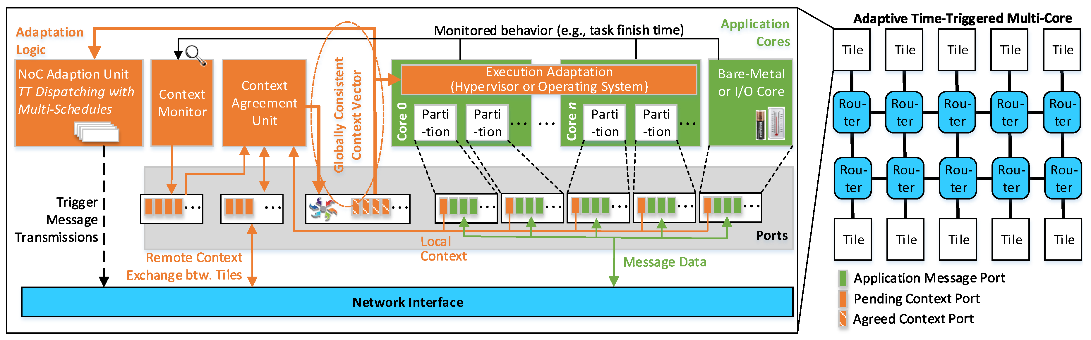
Figure 2 gives an overview of the
Adaptive Time-triggered Multi-core Architecture (ATMA). The architecture encompasses tiles, which are interconnected by a NoC. The NoC consists of routers, each of which is connected to other routers and to tiles using communication links. A tile includes three parts: cores for the application services (cf. green area in
Figure 2), adaptation logic (cf. orange area in
Figure 2) and the NI for accessing the NoC (cf. blue area in
Figure 2).
The cores of a tile can be heterogeneous encompassing processors that are managed by an operating system, processors with bare-metal application software or state machines implemented in hardware. Regardless of the implementation, message-based ports provide the interface of the cores towards the adaptation logic and the NI.
The adaptation logic is the key element for the consistent and timely processing of context events. It includes the following building blocks:
The context monitor is responsible for observing the behavior of the cores and generating local context information. An example is a slack event when a task finishes before its WCET. Another example of a context event is a relevant change of state observed via input/output channels (e.g., low battery state and environmental conditions).
The context agreement unit establishes unanimous context information, which is globally consistent at a chip-wide level. Despite multiple clock domains and the occurrence of faults, the context agreement unit ensures that all operational tiles possess identical context information.
The NoC adaptation unit contains multiple schedules and the next schedule is chosen based on the context information provided by the context agreement unit. The potential switching between schedules is triggered in a time-triggered manner and has its own schedule. Since the context information is chip-wide consistent, it is guaranteed that all tiles perform aligned schedule changes.
In analogy to the adaptation at the network level, adaptation for the execution resources is supported by the execution adaptation. The consistent context information serves for switching between cyclic schedules of time-triggered operating systems or hypervisors.
The NI serves as an interface to the NoC for the processing cores by injecting the messages into the NoC as well as delivering the received messages from the NoC to the cores. The NI generates the message segments (known as packets and flits), in the case a message needs to be injected into the interconnect. At the opposite direction, i.e., for the incoming messages, the NI assembles each message from the received segments and stores it to be read by the connected core.
3.2. Local and Global Adaptation
We distinguish between local and global adaptations. Local adaptations are those changes in a subsystem, which do not introduce any changes in the use of shared resources. For example, dynamic slack in a processor core would result in the early completion of a task and the generation of a message before its transmission is due according to the time-triggered schedule. DVFS can be used locally within the processor to complete the task and produce the message just before the scheduled transmission time. In this case, energy is saved locally without any implications on the rest of the system and the time-triggered schedule.
Global adaptations, in contrast, are those changes in a subsystem, which result in a temporal or spatial change in the usage of the shared resources. For example, dynamic slack of a sender can be used to transmit a message earlier. The receivers can then start their computations earlier with more time until their deadlines. The longer time budget can be used for DVFS in the receivers, thereby saving more energy because several receivers are clocked down instead of a single sender. However, a new schedule is required for global adaptation in order to preserve the ATMA properties. Such global adaptations and schedule changes must not introduce an inconsistency in the system and thus need to be harmonized over the entire chip.
To establish a chip-wide aligned adaptation of subsystems, the operation of the dispatchers of different tiles shall be harmonized by a
global time base to have a common understanding of the time, despite different clock domains. The global time base is a low-frequency digital clock, which is based on the concept of a sparse time base [
20]. The global time base provides a system-wide
notion of the time between different components.
3.3. Fault Tolerance
ATMA offers inherent temporal predictability and fault containment for processing cores. The adaptation unit is deployed with a schedule that provides a priori knowledge about the permitted temporal behavior of messages. Using this knowledge, the adaptation unit blocks untimely messages from the processing cores, thereby preventing resource contention in the NoC. Likewise, the adaptation units and the network interfaces autonomously insert the source-based routing information into messages, thus a faulty processing core cannot influence the correct routing of messages in the NoC.
While faults of the processing cores are rigorously contained, faults affecting the adaptation units, context-agreement units, network interfaces and routers have the potential to cause the failure of the entire multi-core chip. In previous work on time-triggered multi-core architectures, the network interfaces and routers have thus been denoted as a
trusted subsystem [
6]. The risk of a failure due to design faults can be minimized through a rigorous design of these building blocks.
Two strategies can be distinguished for dealing with random faults of the trusted subsystem:
Fault-tolerant trusted system: Fault-tolerance techniques can be deployed for the adaptation units, context-agreement units, network interfaces and routers. For example, these building blocks can be synthesized as design units with triple modular redundancy [
21].
Consideration in reliability models and off-chip fault-tolerance: Alternatively, the designer can accept the risk from random faults and consider the fault propagation probabilities from adaptation units, context-agreement units, network interfaces and routers, which potentially represent single points of failures. Evidently, this strategy is only reasonable if the chip area consumed by the processor cores is dominant. In many safety-critical systems (e.g., ultra-reliable fail-operational systems such as ADAS systems with highest SAE levels [
22]), on-chip fault-tolerance mechanisms are complemented by off-chip fault-tolerance techniques because of non-negligible probabilities of chip failures (e.g., due to shared power supply, common clock source, spatial proximity [
23] (p. 155)). In these systems, the fault-tolerance mechanisms of ATMA serve for increasing the reliability, but do not replace off-chip redundancy.
Another prerequisite for correct adaptation is the correctness of the schedules. The state of the art offers algorithms and tools supporting the verification of time-triggered schedules (e.g., TTPVerify [
1] (p. 489)), which can be applied on each node of the multi-schedule graph.
4. Meta Scheduling
The meta scheduler [
24] is an offline tool for computing time-triggered schedules considering the system’s contextual, spatial and temporal dimensions. Different schedules are computed for all relevant context events and are deployed in the NoC adaptation units and the execution adaptation. For a given context, the corresponding schedules determine the dispatching of each resource at any point in time within the system’s period.
Two types of schedules are taken into consideration: The computational schedules are computed for the tasks and define their allocation to cores and their start times. The communication schedules define the paths and injection times of the messages on the NoC. The computational and communication schedules must be synchronized as the messages to be sent are computed by the tasks.
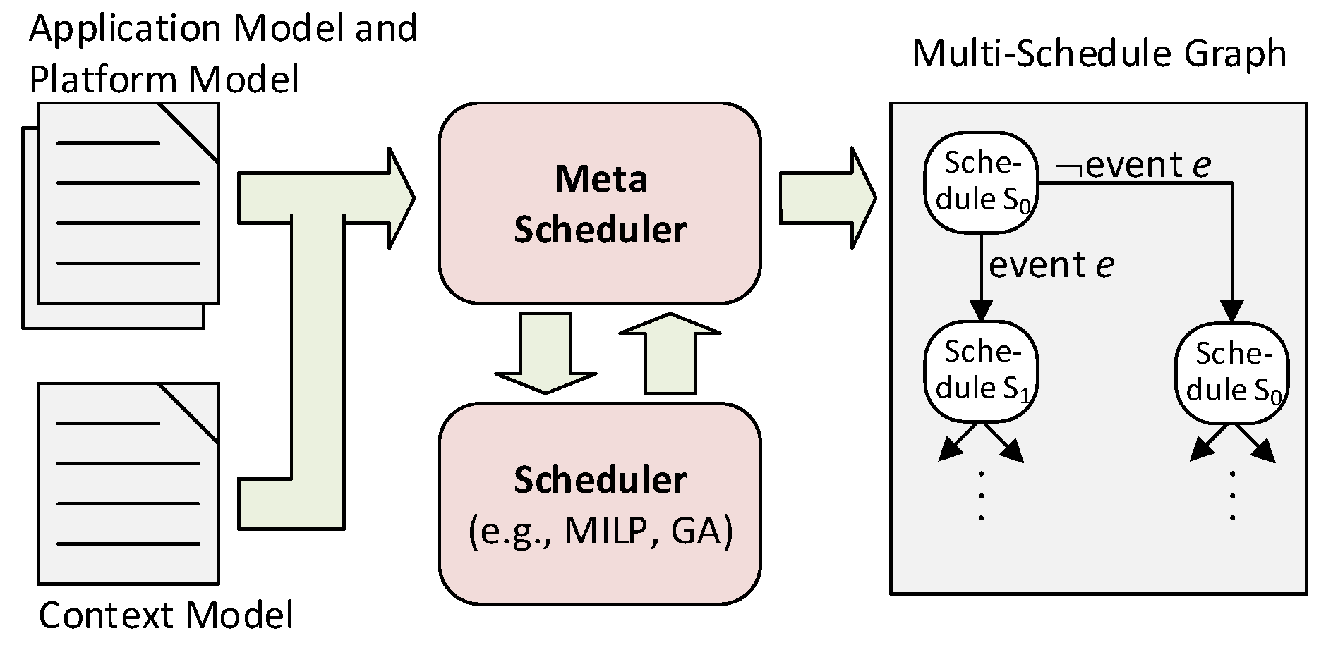
4.1. Input Models
The meta scheduler requires the following three types of models as input (cf.
Figure 3):
Application Model: The application model describes the computational tasks with their deadlines, WCETs and resource requirements (e.g., memory, I/O). The assumed WCET of a task is based on its criticality [
25]. High-criticality tasks must be considered with a more pessimistic WCET in order for the schedule to assure that applications have enough time to finish the task within the assigned time frame. In addition, the application model describes each message with its sender task and receiver tasks, thereby reflecting the precedence constraints between the tasks and the messages.
Platform Model: The platform model informs the meta scheduler about the available hardware resources, such as cores, memories, I/Os, routers and the interconnection pattern of routers.
Context Model: The context model covers all context events that are relevant for the adaptation including faults, dynamic slack, resource alerts and environmental changes. Examples of faults are permanent failures of cores and routers, which require a recovery action such as the reallocation of tasks and messages. Dynamic slack of a task occurs if the execution time of the task is shorter than its WCET. It can be exploited by DVFS or by clock/power-gating of resources to save energy. Alternatively, dynamic slack can be passed to subsequent tasks or messages. An example of a resource alert is a high thermal level of passively-cooled electronics that demands for a reduction of the computational load to avoid thermal damage. Likewise, certain battery levels motivate degradation concepts such as disabling comfort functions in an electric vehicle. Environmental changes are context events that originate from outside the computer system, e.g., entering of the takeoff phase in an airplane.
4.2. Meta Scheduling
The meta scheduler computes a Multi-schedule Graph (MG) using the application, platform and context models. The MG is a directed acyclic graph of time-triggered schedules, which are precomputed at development time. At any instant during runtime, the time-triggered system is in one of the nodes of the multi-schedule graph. This node defines the temporal and spatial allocation of all computational and communication resources. Upon a relevant event from the context model, the node is left and the system traverses to another node of the multi-schedule graph.
To compute the MG, the meta scheduler repeatedly invokes a scheduler (cf.
Figure 3). The scheduler takes an application model and a platform model as inputs and computes a time-triggered schedule fulfilling the scheduling constraints (e.g., collision avoidance, precedence constraints, and deadlines). The decision variables are the allocations of tasks to cores, start times of tasks, messages paths along routers, message injection times and fetch times for the adaptation manager to read the latest instance of the context vector.
Decision variables also include parameters for improving energy efficiency such as the time intervals for clock gating and DVFS. The time-triggered schedule specifies the frequencies of cores and routers in different time intervals of the time-triggered schedule [
24,
26]. The resulting overhead such as the time needed to adjust the voltage needs to be considered in the constraints of the optimization problem.
The state of the art encompasses a broad spectrum of algorithms (e.g., genetic algorithms, SAT/SMT, and MILP) to solve this static scheduling problem.
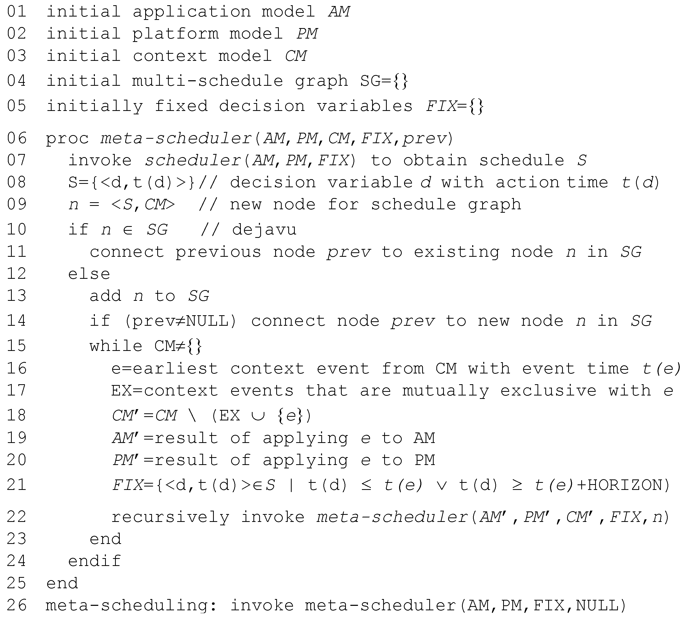
The algorithm of the meta scheduler is depicted in
Figure 4. The meta scheduler starts in an initial state
assuming the absence of faults, slack events and resource alerts. It invokes the scheduler to obtain a schedule for
. The meta scheduler then performs a time step until one of the events from the context model can occur.
Some events such as the occurrence of a particular dynamic-slack value occur at specific points in time (e.g., termination of a task after 50% of its WCET). For events that can occur at any time such as faults and resource alerts, predefined sampling points for fault detection or resource levels are assumed.
The meta scheduler applies the earliest context event, which results in a changed application or platform model. For example, a fault event results in the removal of a resource from the platform model. A dynamic slack event results in a shorter execution time of a task. Thereafter, the meta scheduler invokes the scheduler again to compute a new schedule for the updated application and platform models. Some decision variables are fixed in the new scheduling problem, namely those that correspond to actions before the time of the processed context event.
Subsequently, the meta scheduler continues to perform time steps, each time applying the context event, invoking the scheduler and adding the new schedule to the MG. In this process, the meta scheduler considers the different potential state traces. For example, the second potential context event will be applied in both schedule as well as in schedule . Therefore, each context event results in a branching point of the MG, since the context event may occur or it can remain inactive.
The meta scheduler considers mutually exclusive events. For example, a certain dynamic slack value for a task precludes another dynamic slack event for the same task.
A major challenge in meta scheduling is the avoidance of state explosion in the MG. The meta scheduling addresses this challenge using the following techniques:
Reconvergence of paths in MG. Whenever the meta scheduler computes a new node for the MG, it is checked whether this node was generated before. In this case, the meta scheduler connects the predecessor node to the existing node and terminates the further exploration of the current path (see Line 11 in
Figure 4).
Reconvergence horizon. For a given context event, the new schedule may only differ from the previous schedule within a limited time interval after the occurrence of the context event. All decision variables after this horizon are fixed in analogy to the decision variables corresponding to actions before the time of the context event (see Line 21 in
Figure 4). Thereby, reconvergence of paths in the MG is ensured.
The size of the MG depends on the application, platform and context models. There is a linear relationship between the size of the MG and the number of tasks and messages in the application model, since the schedule must provide a resource allocation for each of these elements from the application model. In addition, the size of the MG depends linearly on the number of resources, which are deployed with dedicated schedules such as cores in case of source-based routing. For those resources, which are only referred to with indices by the schedules, there is a logarithmic relationship between the schedule size and the number of resources (e.g., routers in case of source-based routing). Without reconvergence, there would be an exponential relationship between the number of events in the context model and the schedule size. With a constant reconvergence horizon, there is a polynomial dependency between the number of events and the size of the MG [
19].
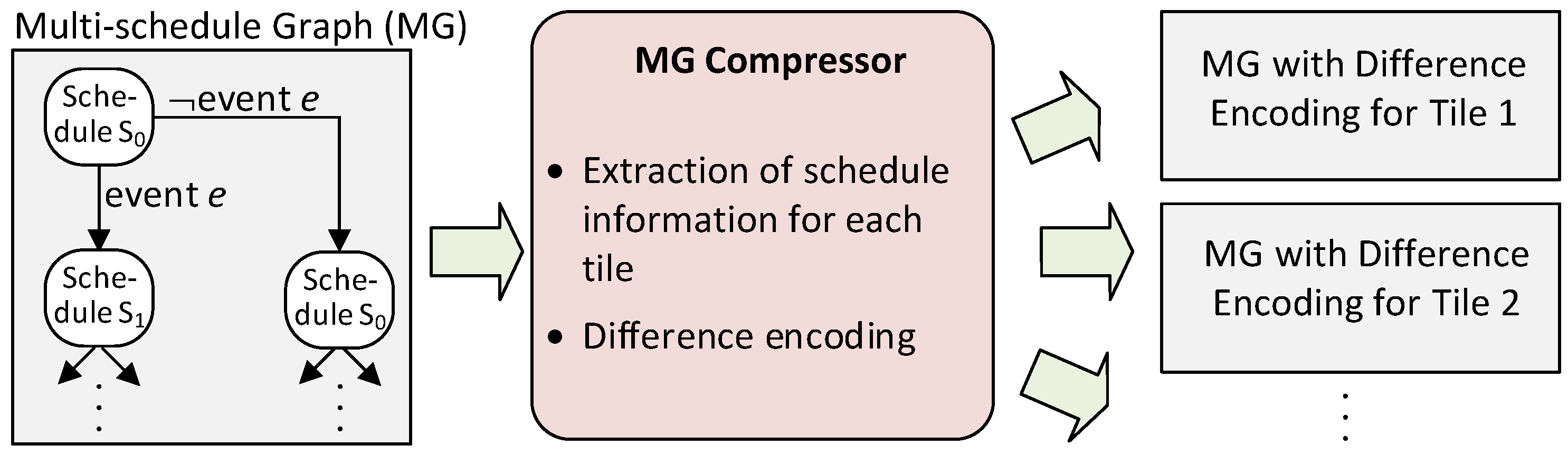
4.3. Tile-Specific Schedule Extraction and Difference Encoding
Even with reconvergence, the meta scheduler can still generate MGs with hundreds or sometimes thousands of nodes. Storing those schedules in the memory space of the tiles would consume significant chip resources. Therefore, we extract an individual MG for each tile and we introduce difference encoding. This transformation of MGs is performed by the
MG compressor in
Figure 5.
The meta scheduler computes a MG where each node provides a schedule for the entire system with all tiles. However, an event will typically lead to changes in message injections at only a small subset of the tiles. Therefore, the graph compressor extracts graphs for the individual tiles from the MG. Each of the resulting tile-specific graphs contains a subset of the original nodes and the nodes contain a subset of the decision variables. Consequently, the resulting graphs are significantly smaller than the original MG.
Each tile is deployed with its complete base schedule, but it stores only the differences of the other schedules in the graph-based structure. As shown in
Figure 5, the MG generator extracts for each tile the schedule information and their changes and stores them in a format that is suitable for the NoC adaptation unit. The NoC adaptation unit, in turn, uses the schedule information to control the source-based NoC and to change the NI behavior at runtime based on the global context information that is provided by the context agreement unit.
The effectiveness of the difference encoding depends on the number of tasks and messages with changed temporal/spatial resource allocations after an event. The ratio between the reconvergence horizon and the makespan provides a lower bound for the compression ratio, if the number of messages and tasks per unit of time is uniform throughout the makespan.
The effectiveness of the schedule extraction is determined by the number of resources (e.g., tiles in case of source-based routing) with changed scheduling information after an event. In the worst-case, all resources are effected by an event, thus yielding no benefit from the schedule extraction. However, typically only a small fraction of the resources requires updated schedules after an event. For example, the extraction results in an average reduction of the schedule size by 71% in the three experimental scenarios described in
Section 7.
The compression also has an impact on the fault-tolerance of the multi-core architecture. On the one hand, the reduced size of the schedule information decreases the susceptibility to Single Event Upsets (SEUs). On the other hand, an SEUs affecting the schedule information for a task or a message can have a more severe effect, potentially corrupting also the parameters of subsequent tasks and messages.
5. Context Monitor and Agreement Unit
All decisions taken by the adaptation unit are taken in a distributed manner at each tile. This helps to avoid having a central tile with the role of a managing device that collects the information of all tiles and pushes the new schedule to the entire system. Otherwise, such a tile would represent a single point of failure and could degrade scalability as well as performance. However, in the proposed distributed manner for decision making, we must ensure that all tiles are aware of the same global context to achieve a coherent distributed decision process. Inconsistencies in the global view can lead to inconsistent schedule changes, which in turn can cause collisions on the NoC and deadline misses.
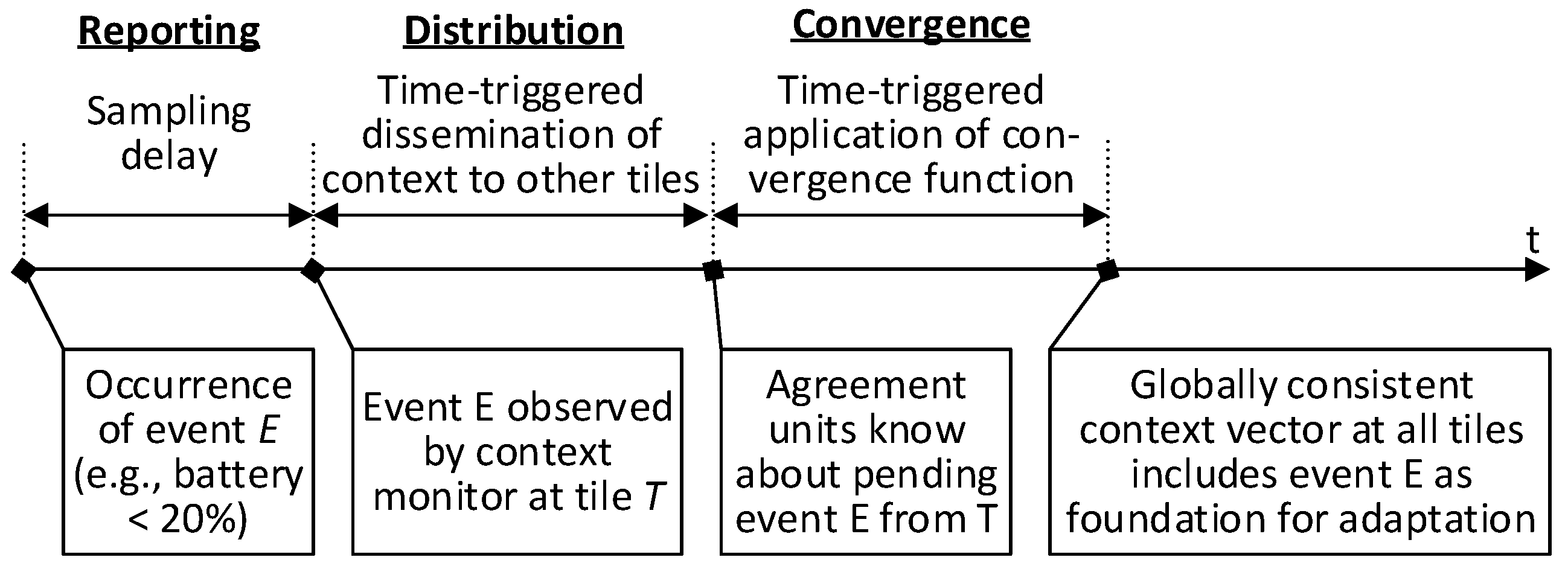
As shown in
Figure 6, the context monitors and the context-agreement units in ATMA establish a global view on the context using the following three steps: (1) context reporting, (2) context distribution; and (3) context convergence. At the beginning of the process each tile has only a local view on the context and is not aware of the status of the other tiles. The three steps are explained in the following.
5.1. Context Reporting
The context monitor focuses on the collection of the local context events within the associated context-agreement units.
We differentiate events based on their temporal properties and the safety implications:
Synchrony.Synchronous context events are predictable in terms of their occurrence time and thus can be checked at particular points in time. Such events either happen at a particular time within the period or they will never happen. This kind of events allows for predictable changes. For instance, if slack happens, it can be used for clock gating or for applying DVFS. Asynchronous context events, on the other hand, happen at random and unconstrained points in time throughout the system lifetime. They indicate a degradation of the system health or resource availability which needs to be reacted to (e.g., fault or low battery level). These events are detected at runtime through periodic sampling performed by the respective context monitors.
Urgency. The urgency of a context event indicates how long the information about its occurrence can be used before it loses its worth for the adaptation. Slack for example is highly urgent, as it expires at the latest by the corresponding task’s WCET. The synchronous events have a predictable offset between the potential occurrence and the resulting schedule change, therefore we can schedule the agreement to fit to the event’s urgency. Asynchronous events, on the other hand, are unpredictable in terms of their occurrence. These events can only be sampled and agreed on regularly, which can lead to protocol overhead, as the events may not occur at all during runtime. The more often the asynchronous events are monitored and agreed on, the faster the system can adapt to them. Depending on the safety requirements and the dynamics of the environment, a frequent observation of the context can be necessary for fault tolerance, as the adaptation of the network must be performed quickly after the fault event is detected. Hence, the frequency for the sampling of asynchronous events is a trade-off between the overhead caused by the agreement and the gain that a short delay for reconfiguration can provide for the system.
Safety. Safety-critical events and non-safety-critical events can be distinguished depending on the impact with respect to functional safety. For example, fault recovery through adaptation can be necessary to avoid critical failure modes of the system after fault events. In contrast, slack events are often relevant for energy-efficiency and availability without direct safety implications.
The context reporting is performed by context monitors in ATMA. These monitors observe the system state with respect to relevant indicators serving as context. The context typically comprises both state information from within the computer system and from the environment. Therefore, monitors and sensors are realized in hardware and software. Software monitors are driver functions that can be used by the application to give direct feedback to the agreement unit. Hardware monitors contain sensors to evaluate the system or the environment. The output of the monitors consists of a bit for every potential event, indicating whether the event actually occurred. For example, an event can represent the exceeding of a threshold value at a sensor (e.g., battery level and temperature).
This information is encoded in a bit string where each event is mapped to a single bit within the string. The event bit thus indicates if the event occurred. This context string is prepared by each tile locally and thus encodes only the locally observed events, therefore we refer to this bit string as the local context. This local context bitstring is the information that is distributed in the following phase.
The monitors write the context information into dedicated ports. Each context event has a dedicated bit in one of the ports.
5.2. Context Distribution
The agreement on the context is realized by a broadcast protocol, which sends the messages with the context using a ring relay between all tiles, meaning that a message is sent by each tile to its neighbor and gets incrementally relayed until reaching the original sender [
11].
The protocol is triggered periodically and executed by each context-agreement unit at the same time.
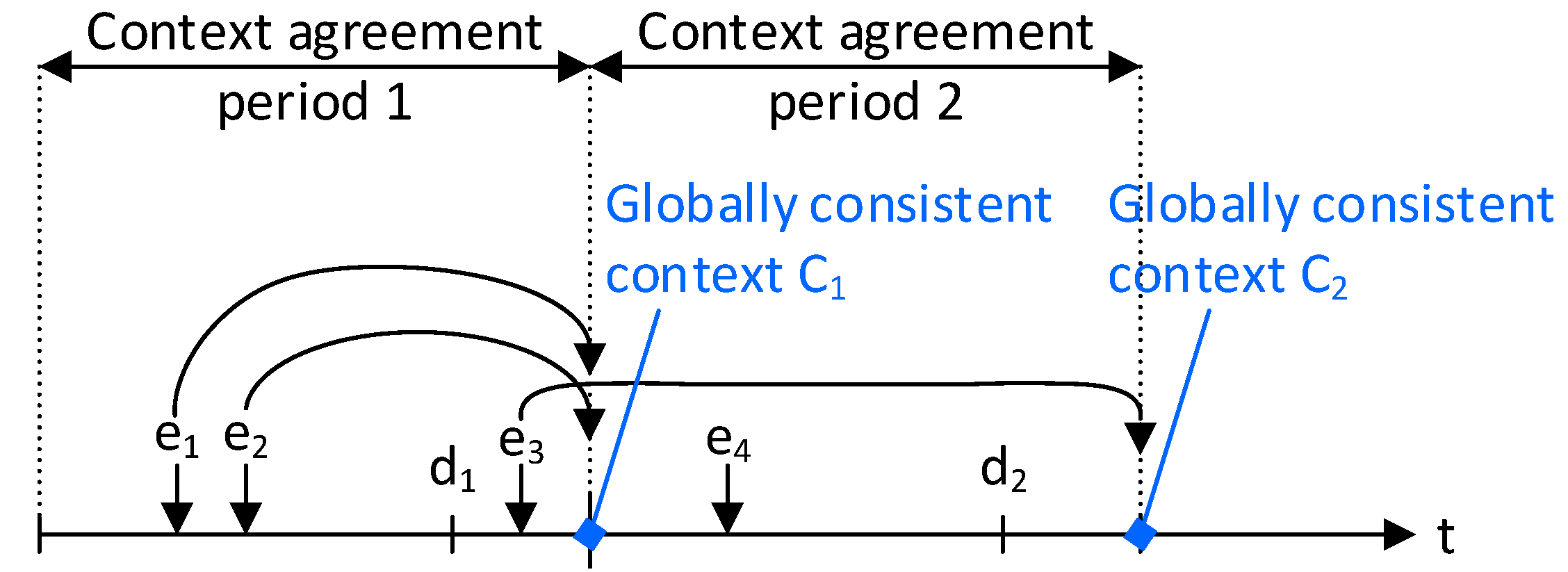
Figure 7 shows which events are agreed upon in an example scenario. The start instant of the agreement process serves as a deadline
for the event reporting of period 1 and all events that happen before
are taken into consideration. Events happening after
are considered for the next period, even if they occur during the context distribution phase of the protocol. Upon the trigger, the context-agreement unit reads the context ports and assembles a local context vector by concatenating the context information for different events. Once the information is gathered, the local context vector is sent to the other tiles within an agreement message that identifies the context string using the source tile id [
11].
This can be done via the NoC or via a dedicated network [
11]. The use of the NoC involves no hardware overhead for the implementation, but the agreement messages need to be added to the scheduling problem. This extension can render the communication more difficult to be scheduled. In such cases, a dedicated second network can be used. For the evaluation in
Section 7, we implemented a FIFO ring structure where the agreement messages can be sent at arbitrary times without consideration of the application communication at the NoC. This implementation has shown to be able to save more energy than a NoC implementation in a benchmark setup [
11].
Each tile in the FIFO ring sends its local context vector to its direct neighbors. This way no collisions can occur as the links that are used are predefined. Once the local context is sent, the tile also receives local context from its neighbors. The tile extracts the new information and saves it locally. Afterwards, it relays the received context to the next neighbors. This way, the local context is transmitted within a ring-like structure between all neighbors until it returns back to its original sender. There the sender knows that it has received all context information in the tile and it can proceed to build the global context vector. This exchange takes n transmission hops, with n being the number of tiles in the network, as the ring needs to be passed completely by all messages. Therefore, the execution time increases with the number of tiles.
5.3. Context Convergence
Once all messages with context information are received, the global context vector is produced. In this phase, the global context can also be converged from redundant information using majority voting. This is important if the same context event is observed redundantly by multiple tiles.
If the context events are observed only by one dedicated tile, the local context information is simply concatenated according to the predefined global context-vector layout in which each tile has a predefined interval where its local information is to be placed.
6. NoC Adaptation Unit
Robust and chip-wide aligned switching of schedules at all tiles are major requirements to ensure consistency and to preserve the properties of time-triggered systems. The NoC adaptation unit supports this requirement based on the assumption of a consistent context vector and correctness of the MG.
The NoC adaptation unit performs time-triggered dispatching of messages by deploying precomputed schedules, each of which is mapped to a particular set of context events. This unit receives the global context vector from the context agreement unit and triggers the ports for transmission of messages to support adaptive time-triggered communication. The global context vector is saved in a dedicated register within the NoC adaptation unit.
The operation of the adaptation unit occurs using the following four steps:
Fetching step: Fetch the global context vector from the dedicated register at the scheduled time.
Compare mask step: Compare the global context vector with a context bit mask to determine the occurrence of specific combinations of context events.
Selection step: Select the new schedule based on the masked signal.
Triggering step: Trigger the message injection for the respective ports based on the new schedule.
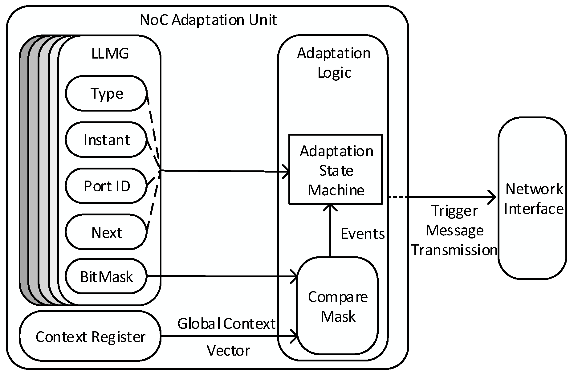
Figure 8 represents the internal structure of the NoC adaptation unit, which is composed of the following three internal building blocks: (1) the context register; (2) the Linked-List Multi-schedule Graph (LLMG) that stores the MG as a linked list; and (3) the adaptation manager.
The global context vector is stored in the context register to be read by the compare-mask building block. The global context vector is fetched at a scheduled time, which is defined by the LLMG.
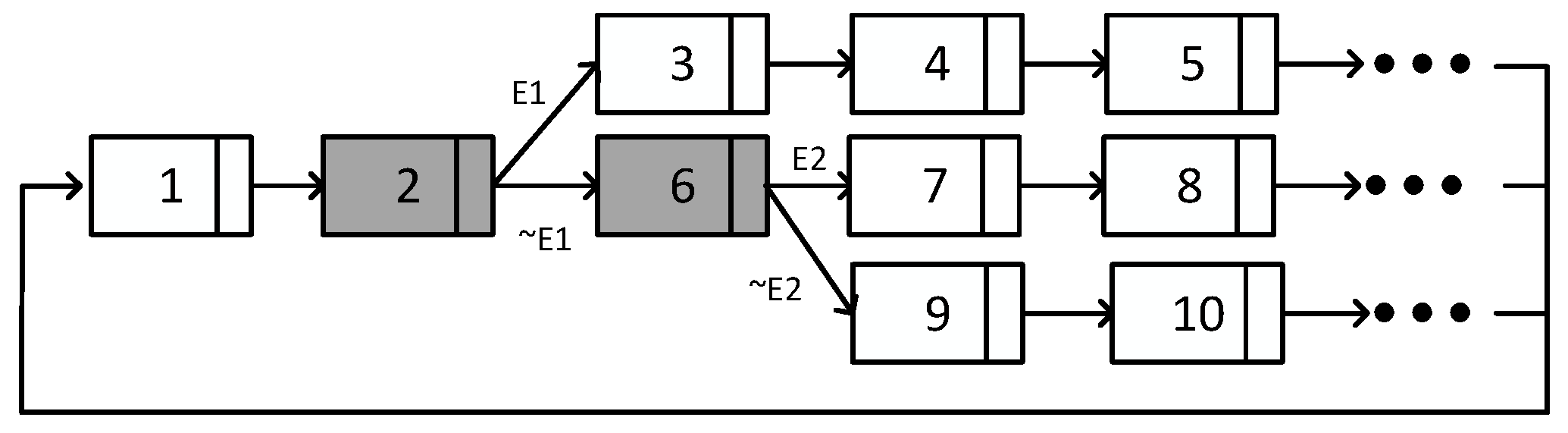
Figure 9 shows an example of a LLMG, which is stored as a circular linked list of instant entries. Each entry in the linked list is associated with an instant of time and address in the schedule file.
Two types of instant entries are provided: message entries and branching entries.
Table 1 presents the content of the two types of entries. The message entries contain Type, Instant, PortID and Next values. The branching entries contain Type, Instant, BitMask, NextTaken and NextNotTaken values:
Type defines the entry type (i.e., message or branching).
Instant represents the injection time of the message or the branching time.
PortID shows the ID of the port, from which the message is injected.
BitMask is a mask to detect the simultaneous occurrence of several events from the global context vector.
Next is a pointer to the next entry of the schedule.
NextTaken is a pointer to the next entry when a specified event has occurred.
NextNotTaken is a pointer to the next entry when the specified event has not occurred.
Figure 9 presents an example LLMG, in which two different events E1 and E2 occur. The type of the entry is distinguished by the color, where message entries are shown in white and the branching entries are shown in gray. The number in each entry represents the address of the entry in the schedule file and the context events are shown on the links between the entries.
The process of selecting the correct schedule is started by tracing the entries of the LLMG, based on the address and next pointers. The adaptation manager is triggered at the instant, which is given by the entries. In the example in
Figure 9, entry 1 is a message entry so the message of the corresponding
Port ID is transmitted at the
Instant specified by the entry. In this entry type, the
Next value points to the address of the next entry. Entry 2 is a branching entry, which points to two different entries. The selection of the next schedule depends on the occurrence of the specified context event. The event occurrence is determined by the global context vector and MaskedBit. In the case of E1 occurrence, entry 3 is selected as the next entry by
NextTaken. If E1 does not occur, then entry 6 is selected by
NextNotTaken. The same operation is applied for the other entries of the LLMG. After applying the operations for all entries, the next pointer of the last entry is followed, which points back to the first entry of the period.
The adaptation manager serves the ports by triggering the message transmissions. The selection of the schedules is fully dependent on the received global context vector and is implicitly consistent with the other tiles, because the context vector is globally consistent and the actions of the different tiles within each schedule are temporally aligned by the meta scheduler.
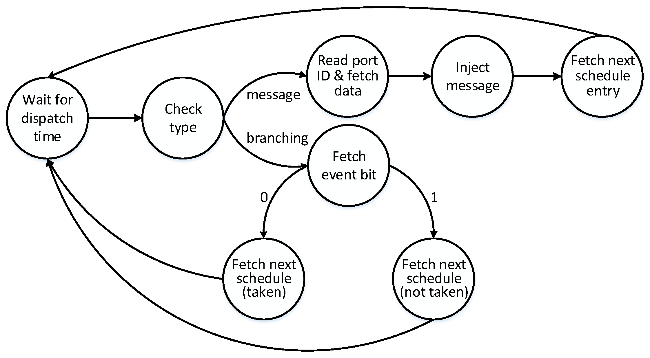
The adaptation manager consists of a state machine and a compare mask. The state machine reads the input from the context vector register and the LLMG for switching schedules.
Figure 10 presents the states and transitions of the state machine.
The state machine wakes up at an instant of time, which is defined by the LLMG. At this instant of time, the type of the LLMG entry is checked. In the message-type entries, the state machine reads the portID and injects the message of the specified port at the instant of time. After the injection, the new entry is fetched by the Next value.
In the case of a branching entry, the global context vector is fetched from the context register at the specified instant of time. In parallel, the BitMask is read from the LLMG. The global context vector and the BitMask values are received by the compare mask to extract the specified event. The event occurrence value can be 0 or 1, indicating whether the event has occurred. Therefore, the NextTaken entry is selected. An event bit 1 means the event has not occurred, so the NextNotTaken entry is selected. After the selection of the next address, the state machine waits again for the dispatching time of the next entry.
7. Results and Discussion
The introduced architecture was instantiated for example scenarios in order to validate the adaptation services. In addition, the scenarios served as an evaluation of the improvements with respect to energy efficiency and investigate the overhead with respect to memory and logic.
7.1. Zynq Prototype
The architecture was instantiated on a Xilinx Zynq-7000 SoC ZC706 FPGA board. The System-on-Chip (SoC) of this board consisted of an ARM-based processing system and a programmable-logic unit on a single die.
The hardware platform comprised four tiles interconnected by a time-triggered NoC [
27]. Each tile was deployed with a network interface, a NoC adaptation unit and a context agreement unit. The Nostrum NoC [
28] served as the basis for the implementation of the adaptable NoC. One tile was located in the processing system and contained two ARM Cortex-A9 processor cores. The other tiles were implemented in the programmable logic, where each tile contained a single core realized as a soft-core MicroBlaze-processor. The resource consumption is shown in
Table 2.
The meta scheduler and the MG compressor served for the generation of the schedules of the tiles, which were loaded to the dedicated memory of each corresponding tile. The meta scheduler is an implementation of the pseudo code in
Figure 4. An existing optimal scheduler [
29] for time-triggered networks was extended to use energy efficiency as the objective function. This optimal scheduler was implemented with IBM CPLEX and repeatedly invoked by the meta scheduler.
7.2. Slack-Based Adaptation Scenarios
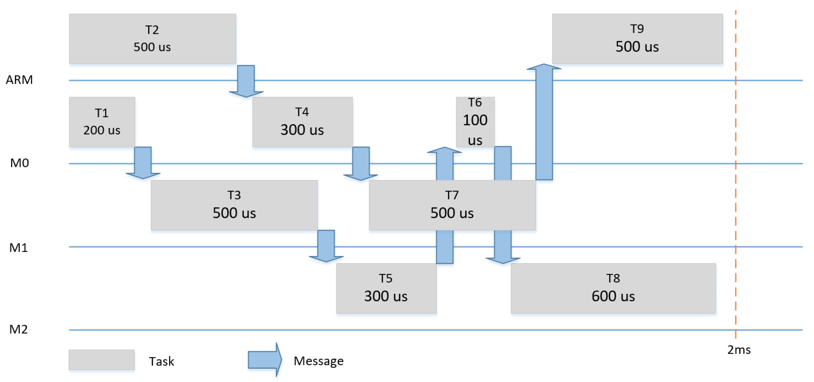
Figure 11,
Figure 12 and
Figure 13 show the three scenarios for the evaluation. In each scenario, different tasks with different WCETs and precedence relationships were hosted by the four tiles. The tasks had a period of 2 ms and it was assumed that each task could be subjected to dynamic slack of 50%.
Table 3 summarizes the input models (i.e., AM, PM and CM) for the meta scheduling in the three scenarios.
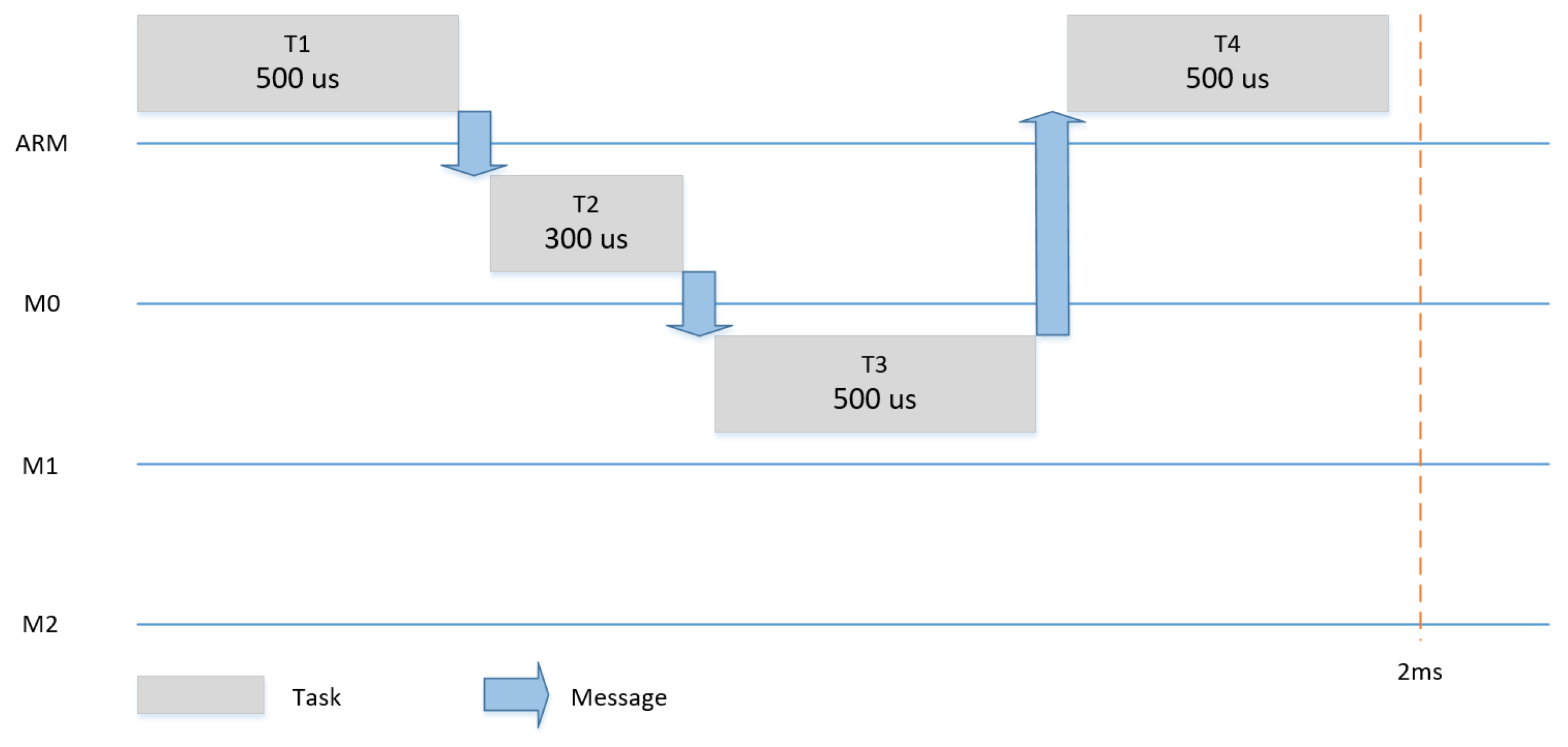
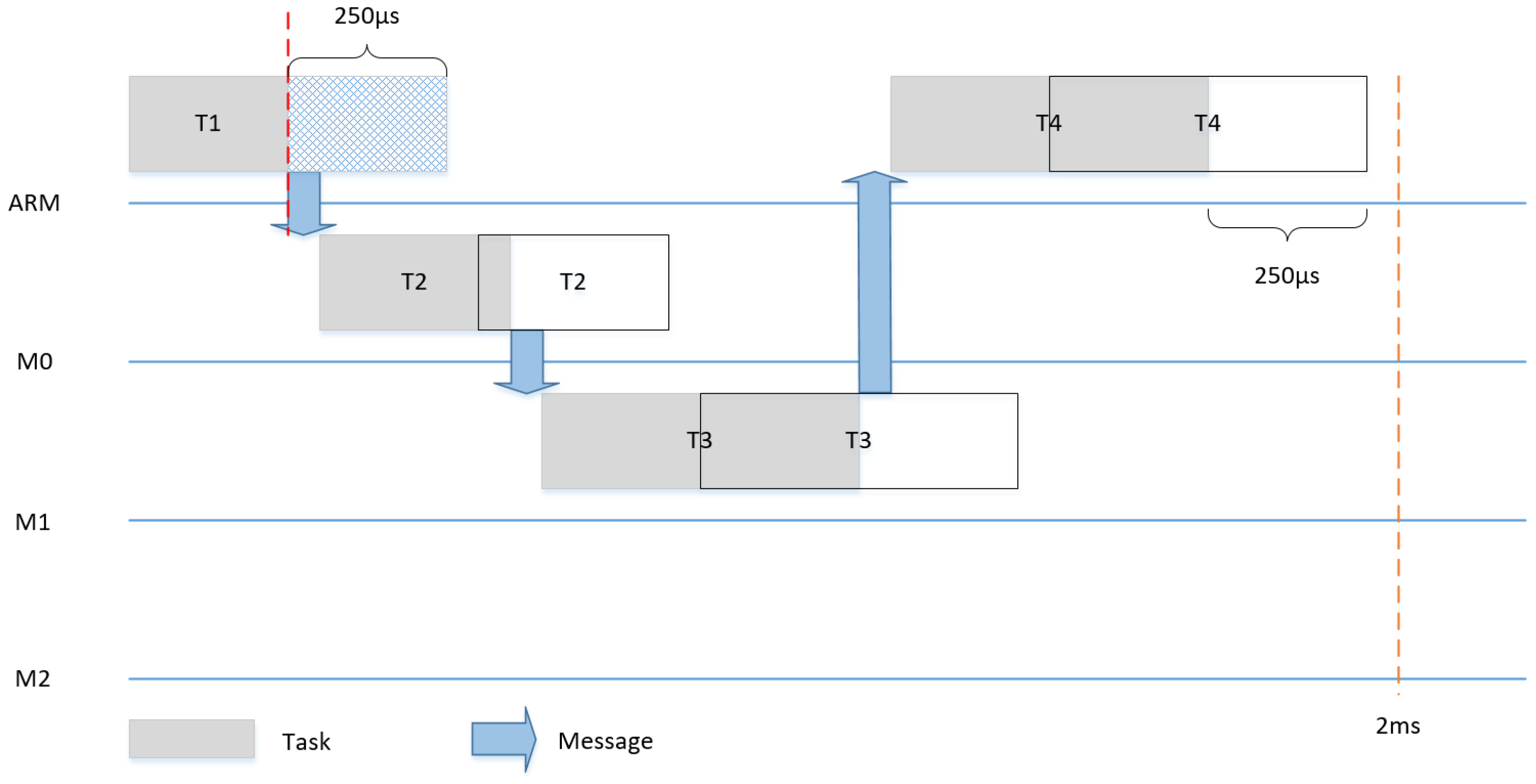
Dynamic slack is the time difference between the WCET of the task and the actual point of time, at which the task ends. Slack can be used to save energy, as, in each execution, some or all tasks can be finished either as planned or earlier. In the case no slack happens, only one schedule can be used, as shown for example in
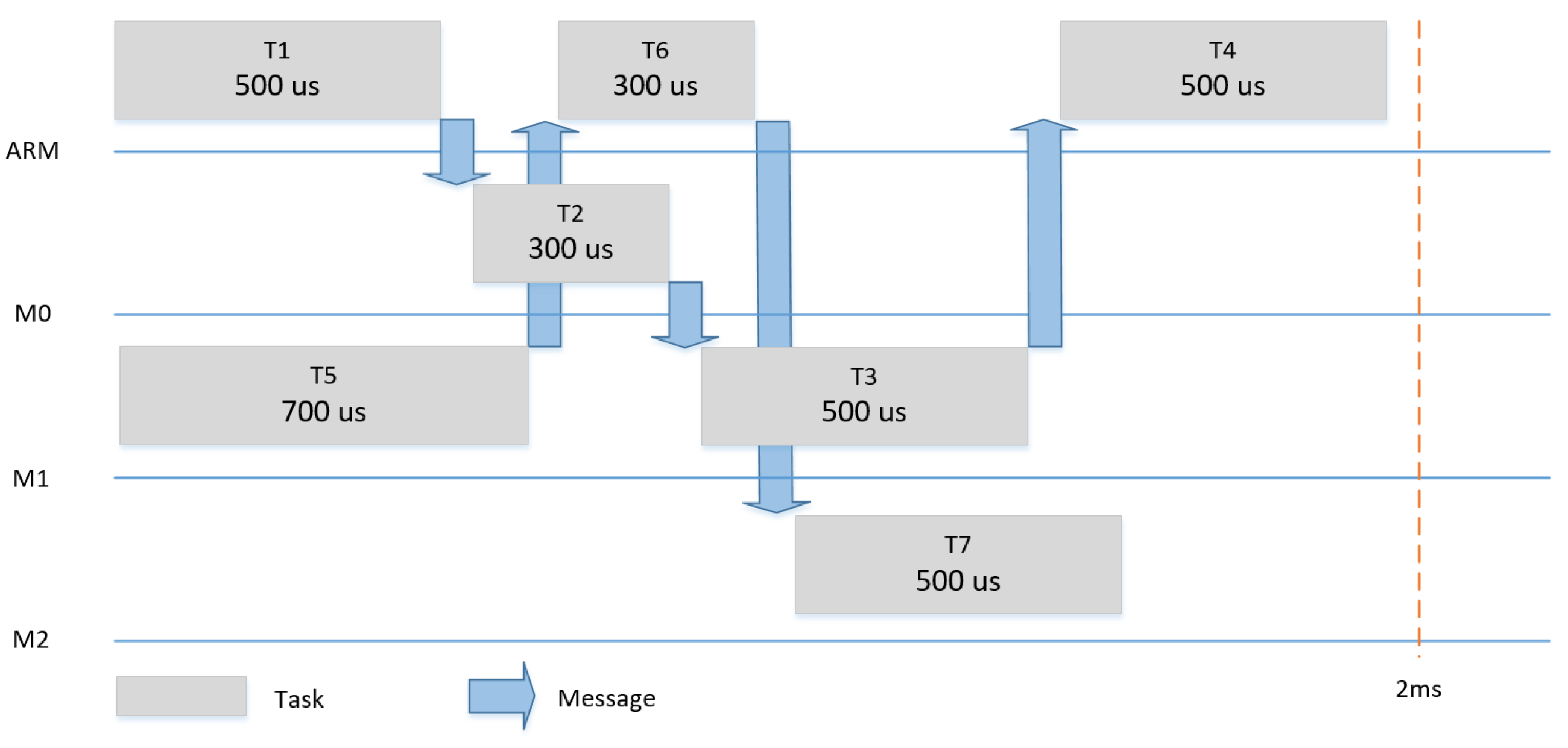
Figure 11. In the case of a slack of 50% (e.g., T1 finishes 250us earlier), we changed the communication schedule to make use of the remaining time of the execution of T1 to start T2 (and consequently T3 and T4) earlier and achieve a shorter makespan for the system, as shown in
Figure 14.
Energy reduction was achieved by clock-gating all tiles, their dedicated IPs and the interconnect. Clock gating aws performed between the completion of the makespan and the start of the subsequent period. In other words, all tiles as well as the NoC were in sleep mode after the termination of the last task, until the next period starts. This procedure was repeated every period.
7.3. Evaluation and Results
The evaluation was performed on the introduced prototype using the UCD90120A device, which is a 12-rail addressable power-supply sequencer and monitor. This chip was mounted on the evaluation board and it aws accessible by the processing system via the PMBus/I2C communication bus.
The experimental results encompass the power consumption for all combinations of slack events, thus showing the power savings depending on the completion times of tasks.
Table 4 summarizes the numerical measurement results for the three scenarios. In each scenario, all possible slack combinations of different tasks were taken into consideration for the computation of the multi-schedule graph [
30]. Each row of the table corresponds to an observed makespan value and it contains the number of schedules in the MG with this makespan, the corresponding power consumption in milliwatt and the power reduction percentage achieved by the proposed adaptation mechanisms. In addition, the table provides the average power reduction percentage under the assumption of a uniform probability distribution of the slack event combinations. This value is pessimistic, because in reality high slack values of tasks are common (e.g., as described by the literature on WCET analysis).
In addition, the memory size for the storage of the generated schedules is indicated in
Table 5. In general, the number of schedules would increase exponentially with the number of tasks. However, the mechanisms for reconvergence, tile-specific schedule partitioning and difference encoding result in a significant reduction of the state space and the memory consumption. The baseline memory consumption and the memory consumption with difference encoding and tile-specific schedule partitioning are shown in
Table 5 as well.
The architectural building blocks for adaptation imposed delays, which added up to 20 clock cycles for a schedule change after a context event in the prototype implementation. The context monitor imposed an implementation-specific latency for the detection of context events. In addition, there was an additional delay of up to one sampling period for asynchronous context events. The prototype contained a hardware implementation of the context monitor in conjunction with synchronous context events involving a delay of two cycles.
The context agreement unit imposed a delay for distributing the context information among all tiles and establishing the globally consistent context vector. In the implementation, four clock cycles were needed for forwarding the context information between tiles using the FIFOs. Hence, 16 clock cycles were needed for the prototype system with four tiles.
The state machine of the adaptation unit in the prototype required two additional clock cycles for each message compared to the non-adaptive NoC in order to process the compressed schedule information and to traverse the linked lists.
8. Conclusions
The presented time-triggered multi-core architecture supports adaptation with multi-schedule graphs, while preserving significant properties of time-triggered systems including freedom from interference at shared resources, implicit synchronization, timeliness, implicit flow control and fault containment.
Architectural building blocks for agreement establish a consistent chip-wide view on context events, which is used by the adaptation unit in each tile for temporally aligned changes of schedules.
The meta-scheduler of the architecture introduces techniques for avoiding state explosion such as reconvergence of adaptation paths with bounded horizons for context events. In addition, memory consumption is minimized using difference-encoding and the tile-specific extraction of schedule information.
The meta-scheduler of the architecture computes Multi-schedule Graphs (MGs), which incorporate for each combination of context events the corresponding fixed scheduling decisions. These decisions include the start times of jobs, message injection times, messages paths and parameters for energy management such as time intervals with different frequency values for cores and routers.
For each schedule of the MG, deadlines, precedence constraints, resource contention and the adaptation overheads (e.g., delays for DVFS and delays for establishment of globally consistent context vectors) are considered. Consequently, correctness can be verified at design time and the presented time-triggered multi-core architecture enables adaptation for safety-critical embedded systems, where significant improvements with respect to energy efficiency and fault recovery can be obtained.
Plans for future work include the experimental evaluation of the fault tolerance using fault-injection experiments and the extension of ATMA towards a hierarchical architecture for the interconnection of adaptable multi-core chips via reconfigurable off-chip communication networks.

 and
and 


