Article

Optimum Redesign of an Agricultural Water Bowser

by
Yashwantraj Seechurn
* and
Ritish Boodhun
Mechanical and Production Engineering Department, University of Mauritius, Reduit 80837, Mauritius
*
Author to whom correspondence should be addressed.
Designs 2018, 2(4), 45; https://doi.org/10.3390/designs2040045
Submission received: 28 September 2018 / Revised: 30 October 2018 / Accepted: 31 October 2018 / Published: 5 November 2018

Abstract

:
There are many types of agricultural water bowsers on the market, which vary in geometry and size. However, in all such bowsers there are “unused spaces” between the bottom of the tank and the axle. The objective of this research was to design an agricultural water bowser with improved capacity by exploiting the “unused spaces”. This would allow a sufficient amount of water to be supplied to wide areas in a short time. Each concept of agricultural water bowser was generated as an integrated chassis water tank to be hitched to a tractor, and the best concept was chosen using a multi-criteria decision-making methodology (house of quality matrix and Pugh selection matrix). The selected design consisted of an U-shaped angle bent bottom sheet welded to a top circular sheet. The Agreement Dangerous Road (ADR) European standard was used for the sizing of the bowser and the selected material was S275 steel. The resultant forces on the shell of the bowser were calculated using analytical methods. A 3-D model of the bowser was developed in SolidWorks 2015, and the static structural analysis tool was used to examine stresses on the body for various types of loading, roads, and driving maneuvers. The shape and size of the bottom part of the proposed bowser increased the capacity of the tank by 20.3%.

1. Introduction

Agricultural water bowsers are used to transport water for crop irrigation in agricultural lands that are situated in regions with insufficient rainfall, and which are restricted from water supply. The mobility of water bowsers allows farmers to move water where and when the need arises. They are extremely beneficial to agriculturists as they can easily access hard to reach locations, such as in between planted crops. The capacity of water bowsers generally ranges from 1000 to 10,000 L, and are designed to be durable and meet international standards of production. The presence of a large variety of water bowsers on the market facilitates farmers in choosing water bowsers of appropriate size for their intended applications. However, in all existing agricultural water bowsers there are “unused spaces” between the bottom of the tank and the axle (Figure 1). The objective of this research is to design a tractor site-towable water bowser with improved capacity by exploiting these “unused spaces”. Several factors should be taken into consideration during development of the bowser such as the height of the center of gravity, which causes constraints in design, and the cross section of the tank, which plays an important role in structural strength and stability.

1.1. Chassis

The chassis is a very important part of a vehicle as it carries all of the loads of the different parts of the vehicle, and its failure would lead to the collapse of the whole-body system. It is desirable to design a chassis which will be cost effective, light, and able to withstand maximum payload. However, the primary concern is to satisfy safety requirements prior to reducing weight for fuel economy purposes [1]. A chassis should be strong enough to withstand shock, twist, vibration, and other stresses, and, apart from strength, it should have good bending stiffness for better handling characteristics [2]. Among the different types of chassis (ladder chassis, backbone chassis, monocoque chassis, and others), the ladder type chassis is most frequently used for heavy vehicles due to its better bending and torsion strength [3]. It is made up of pressed steel members and consists of two side members, which are connected by several cross members to provide a rigid structure. In trailers, the cross members are generally welded to the side members [1]. This type of chassis is used on “body-on-frame” types of vehicles and is mostly used in heavy trucks and buses [4]. The cross-sections of chassis frames [5] include:
  • C-shaped: The C-rails are the most common type and are used in almost every vehicle. A flat piece of steel is rolled on both sides to form a C-shaped beam.
  • Boxed: It is made by welding two similar C-rails together or by bending a flat piece of steel into four sides and then welding where both ends meet.
  • Hat: It has a “U” geometry and is not frequently used due to its low strength.
  • I-shaped: The I-rails are used on all types of trucks as the cross members in structures.

1.2. Axle

An axle is a central shaft passing through the center of rotating wheels. The basic functions of the axles are to transmit driving torque to the wheel and maintain the position of wheels relative to each other. They also bear the vehicle and cargo weight [6]. Axles are categorized as live or dead types. Live axles move with the rotation of the wheels, whereas dead axles are stationary axles that do not rotate with the movement of wheels [7]. There are two types of axles that are commonly used in trailers, namely spring axles and torsion axles. Spring axles are cheaper and require more labor to install, as compared to torsion axles. Leaf spring axles have a set of metal springs and torsion axles have rubber springs for suspension [8].
Trailers that are intended to carry a light weight have single axles. However, most trailers are tandem axles and are considered safer than single axle trailers. If a tire blows up in a tandem axle trailer, the other tire will hold the weight and prevent the trailer swerving. Triple-axle trailers are suitable for heavy loads, but the center tire acts as a pivot point during turning and thus wears excessively.

1.3. Vehicle Rollover Stability

Rollover occurs when a vehicle rotates 90° or more about its longitudinal axis and its body touches the ground [9]. The rollover stability of a vehicle is its ability to withstand overturning moments set up during cornering, and is influenced by various factors such as the center of gravity height, the track width, and the kinematic and compliance properties of the suspension system [10].
Due to the low roll stability of commercial trucks, there is a significant amount of truck rollover accidents. The static rollover threshold (SRT) is the basic measure of roll stability and is expressed as the lateral acceleration in gravitational units (g). An increase in the load of commercial trucks lowers the static rollover threshold [11]. A low value of static rollover threshold signifies a reduced roll stability of a vehicle.
Vehicles rollover can be divided into two types, namely tripped and untripped [12]. A tripped rollover arises when a vehicle hits an object, whereas an untripped rollover occurs from direct result of lateral wheel forces, due to different driving maneuvers such as travelling at high speed during cornering, avoiding obstacles, and changing lane sharply.
Figure 2 shows a “quasi-static rigid body” model where h is the center of gravity height, T is the track width, and m is the mass of the body. Due to lateral acceleration during cornering, a lateral force (FLAT) is induced that acts at the center of mass and results in a moment, which tends to roll the vehicle. The resisting moment, produced by the gravitational force (mg), counteracts the moment from the lateral acceleration to ensure that the vehicle is stable and does not roll. But, as soon as the lateral acceleration becomes large enough, the net resultant force (FR) on the vehicle increases and causes the vehicle to roll. When the lateral acceleration equals a value of “T/2 h”, the center of mass of the vehicle lies exactly above the outside wheels, and the inside wheels lift off the ground. The rollover threshold is the maximum value of lateral acceleration to initiate roll instability. Above this value, rollover of the vehicle can only be prevented by a negative lateral acceleration [13].

1.4. Liquid Sloshing in Road Tankers

Liquid sloshing is the free-surface movement of liquid in a container, which is generated by external vibration, and this phenomenon can lead to engineering problems like instability and structural failures of liquid containers [14]. The free-liquid surface in road tankers can experience massive displacement for even slight motions of the container, which can cause undesirable effects on the stability and controllability of the vehicle [15]. The lateral dynamics of a vehicle can be influenced by three factors that are caused by liquid sloshing in a tanker [16]. These factors are the inertia force, due to the bulk motion of the liquid; the induced force, due to the change in the center of gravity of the fluid cargo; and the resonance force, due to the sloshing frequency and natural frequency of the vehicle. During the braking, turning, or bumping of a tank truck, the unsteady weight distribution in a partly-filled tank, due to liquid sloshing, can change the center of gravity of the truck, which may result in an accident and the reduced working life of tires and other parts [17].
The fill volume and the tank geometry highly influence the magnitudes of the dynamic load shift, slosh forces, and moments [18]. Parameters, like tank motion, liquid fill depth, liquid properties, and tank geometry, determine the amplitude of the slosh and have a direct impact on the dynamic stability and performance of moving tanks [19].

1.5. Material

Although steel is prone to corrosion, it is the most common type of material used in the manufacture of water tanks due to its low cost, durability, availability, and ease of construction. There are alternative materials such as aluminum, fiberglass, polypropylene, and stainless steel, which do not rust and can be used to manufacture water tanks. However, each material has its own drawbacks for water tank construction. There are several methods for protecting steel against corrosion such as coating the tank surface, adding rust-inhibiting chemicals to water in the tank, and adding sacrificial anodes [20].

1.6. Tank Design Standards

The overall height and width are limited by regulation and practicalities during operation. There are two main regulations governing the design of tanks intended for the transportation of hazardous materials, namely CFR 49 (Code Federal Regulation) for the United States and ADR (Agreement Dangerous Road) for the European Community.

1.6.1. CFR 49 (Code Federal Regulation)

Part 178 of the CFR 49 regulation specifies the thickness and the material of the shell and bulkheads, and also mentions about the use of baffles for circumferential reinforcement of the tank shell. The distance between baffles or external stiffeners must be 1.52 m or less [21].

1.6.2. ADR (Agreement Dangerous Road)

The ADR regulation mentions that liquid-carrying tanks should be equipped with strengthening members, like partitions, surge plates, or external or internal rings, and the maximum distance between them should be 1.75 m. Strengthening members may be neglected for tanks having a capacity of less than 7500 L. Furthermore, a surge plate must cover at least 70% of the cross-sectional area of the tank [22]. This regulation established a roll stability limit of 0.4 g for tanks carrying dangerous goods, and states that a clean bore tank compartment not exceeding a capacity of 7500 L should be filled by more than 80% and less than 20% to limit the fluid sloshing phenomenon. Moreover, the maximum width of the tank must be at least 90% of the center of gravity height of the laden vehicle, and vehicles carrying tanks with a capacity of more than 3 m3 must follow ECE regulation No. 111 for lateral stability.

1.6.3. Economic Commission of Europe Regulation No. 111

This regulation states that the static rollover stability of a vehicle must be derived from a tilt table test or an estimate method. The tilt table test requires the vehicle under test to be in full loaded condition, with at least 70% of the volume filled, and it should be securely mounted on a table surface. The table surface is tilted up to an angle of 23° at an angular speed not exceeding 0.3°/s. The static rollover threshold (SRT) of the vehicle should be such that the wheels on one side must not lose contact with the table surface upon tilting. The SRT estimation method requires an overturning lateral acceleration of 4 m/s2 and takes into consideration several factors such as the center of gravity, track width, and the suspension and tire stiffness, which have an impact on the roll stability of the vehicle [23].

2. Materials and Methods

2.1. House of Quality

A house of quality matrix expresses the different engineering targets that need to be achieved for a new product design by considering customer needs, marketing research, and benchmarking information. Figure 3 shows the house of quality matrix for an agricultural water bowser. A product improvement survey was carried out and farmers were requested to indicate the level of importance of various aspects of an integrated chassis water bowser. Agricultural water bowsers from five different companies have also been compared to each other based on the different customer requirements.

2.2. Concept Development and Selection

Six different concepts of tank were considered and the best design was selected using the Pugh matrix. Pugh’s method is a decision-making technique used to select the best concept from alternative concepts by making qualitative and quantitative comparisons [24]. The base of the tank, which would be stiffened accordingly in the product improvement phase, replaced the chassis in all the proposed tank designs shown in Figure 4. In Concept 1, two channel frames were placed parallel to each other. The extreme edges of the top circular sheet were welded along the top edges of the channel frames. The two extreme edges of a rectangular metal sheet, which was at the bottom, were welded to the edges of the channel frames. The curvature geometry near the top of the channel frame reduced the stress concentration. In Concept 2, a bended steel sheet was welded to a top circular sheet. The angled side walls allowed for more space inside the tank, and therefore had a higher capacity as compared to Concept 1. Concept 3 and Concept 4 had elliptical top surfaces, and the steel sheets were arranged in the same way as those in Concept 1 and Concept 2, respectively. Elliptical geometry has a lower center of gravity as compared to circular geometry. Concept 5 shows a tank with an octagonal cross section, which was wide and had a large volume, whereas in Concept 6 the arrangement was similar to Concept 1 and Concept 3, but with a different cross section.
From the first-round decision matrix (Table 1), it was found that Concepts 2 and 4 had the same number of positive points. However, Concept 2 had a smaller number of negative points than Concept 4. Therefore, Concept 2 was considered as the datum in the second-round decision matrix (Table 2). The second-round matrix confirmed that Concept 2 was the best choice for the bowser design.

2.3. Detailed Design
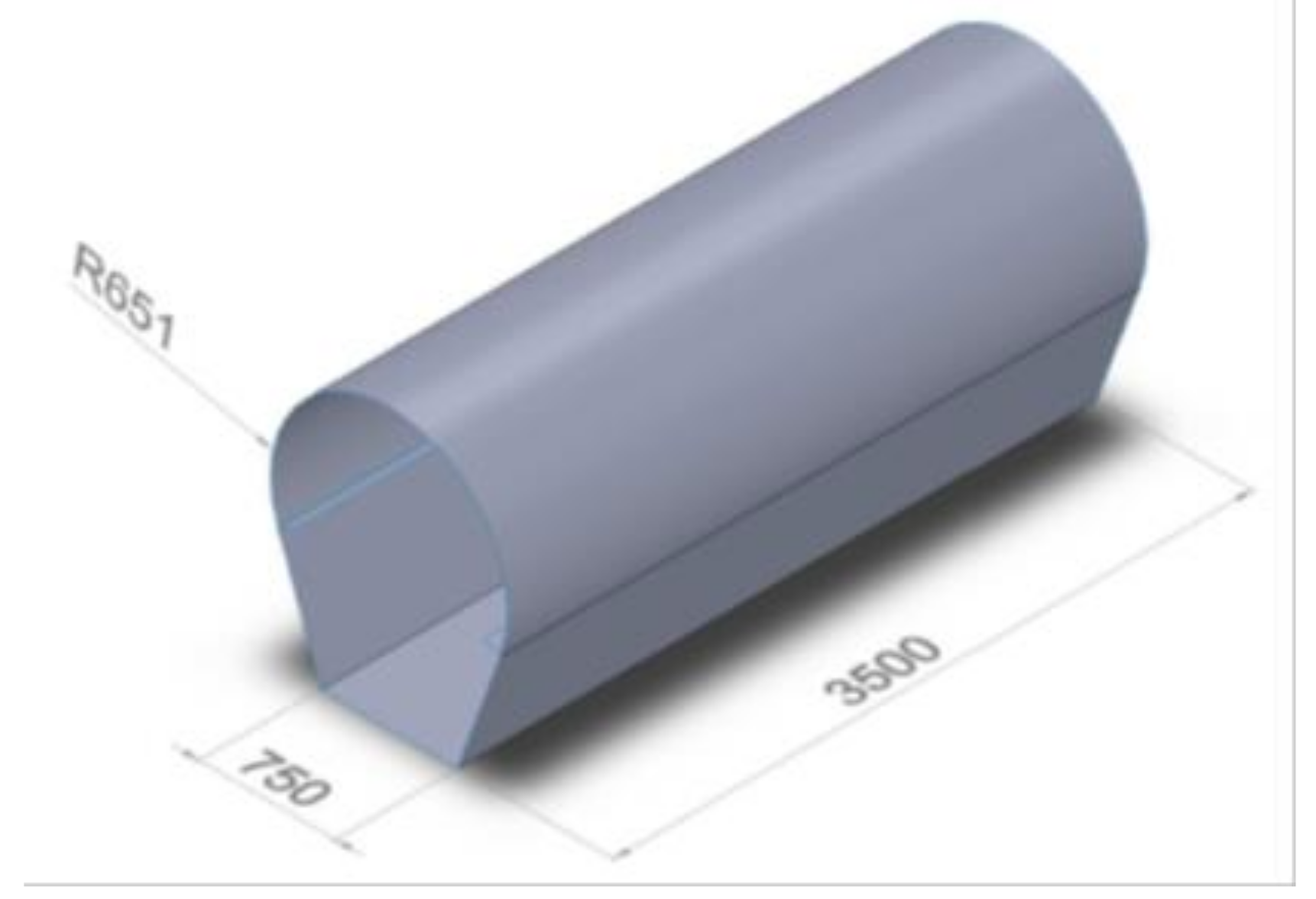
2.3.1. Tank Shell

The material selected for the shell of the water tank was S275 steel. The mechanical properties of S275 steel according to EN10025:2004 are given in Table 3 [25].
According to ADR regulation [22], the ratio of Re to Rm should be less than 0.85 (0.67 for S275 steel) and the elongation at fracture must not be less than 20% (23% for S275 steel). Therefore, S275 was a suitable material for the shell. It also had a good machinability and weldability. The dimensions of the shell (shown in Figure 5) were selected based on standard S275 steel sheets sizes. The cross-sectional area of the shell was 1.59 m2 and the volume was 5.57 m3.
The minimum thickness of the shell was computed using formulae given in subsections 6.8.2.1.17 (Equation (1)) and 6.8.2.1.18 (Equation (2)) of ADR regulation [22], and by choosing the highest value obtained from the two equations.
e = P T D 2 σ λ
where, e is minimum shell thickness (mm), PT is test pressure (equal to 2 times static pressure of water in the shell) (MPa), D is internal diameter of shell (mm), σ is permissible stress (N/mm2), λ is coefficient not exceeding or equal to 1, allowing for any weakening due to welds;
e 1 = 464   e 0 ( R m 1   A 1 ) 2 3
where, e1 is minimum shell thickness of chosen metal (mm), e0 is minimum shell thickness mild steel (mm), Rm1 is minimum tensile strength of chosen metal, A1 is minimum elongation at fracture of chosen metal under tensile stress in %.
By considering a maximum height of 2 m for the tank, the static pressure of water obtained was 19,620 Pa (0.02 MPa) and hence the value of PT was 0.04 MPa.
According to ADR regulation [22], the magnitude of stress (σ) at severely stressed points of the shell, and its fastenings should be less than the lower value of either 0.75 Re or 0.5 Rm, which gave a maximum allowable stress of 205 MPa.
D is the diameter which corresponds to a circular cross-sectional area of 1.59 m2 and was assigned a value of 1423 mm. A value of 0.8 was taken for λ.
By substituting values of the different parameters in Equation (1), a minimum shell thickness of 0.17 mm was obtained.
For shells with a circular cross section of diameter less than 1.80 m, the thickness should be at least 5 mm for mild steel or of equivalent thickness if another metal is used [22]. Using Equation (2), the minimum equivalent thickness obtained was 5.2 mm. Therefore, steel plates having a minimum thickness of 6 mm could be used for the shell.
Based on the data of standard S275 steel plate sizes corresponding to 6 mm thickness, a shell, having dimensions as specified in Figure 5, could be constructed from a 8000 mm by 2500 mm steel plate. Figure 6 shows the two parts that were to be welded to form the shell. The upper part was curved and had an arc length of 2500 mm, while the bottom part was a bended steel plate with a base width of 750 mm, inclined lengths of 692 mm, and flaps of 100 mm at the extreme edges for ease of welding. The front and back faces had thicknesses of 6 mm.

2.3.2. Drawbar

The dimensions and types of bars to be used for construction of the drawbar are illustrated in Figure 7. The drawbar would be welded to the bottom of the tank.

2.3.3. Ring Hitch

The dimensions for the ring hitch were obtained from IS 11270:1985 [26].

2.3.4. Axle Position

According to IS 8213:2000 [27], the length of an axle in a trailer should be 1500 mm or 1700 mm and the position of the axle should conform to Equation (3):
G = 3 B 2 H 8
Figure 8 shows a diagram of a single axle trailer explaining the parameters in Equation (3). The drawbar was welded to the bottom of the tank base such that H was equal to 1486 mm, and B was obtained as 3512 mm by adding the thicknesses of the front and back sheets to the length of the tank shown in Figure 7. Substituting these values in Equation (3) gave a value of 945.5 mm for G.
A square hollow bar of 100 mm × 80 mm, having a length of 1500 mm and a thickness of 6 mm, was chosen for the axle, which would be welded to the bottom of the tank.
ADR regulation specifies that the maximum lateral acceleration allowed for a tank vehicle is 0.4 g and equal to a value of (T/2 h) g [22]. If the track width (T) of the bowser is 1500 mm, the maximum center of gravity height (h) should be equal or less than 1875 mm. If a greater value of track width is considered, the maximum allowable center of gravity height will be higher.

2.3.5. Tire

400R22.5 tires were used for the agricultural water bowser. The 400R22.5 Kargo Radial tire had an overall width of 400 mm and an overall diameter of 1080 mm. A site speed limit of 25 km/h would be adopted and at this speed, and the load carrying capacity per wheel would be 6300 kg.

2.3.6. Baffles

According to ADR regulation [22], surge plates can be neglected for a tank having a capacity less than 7.5 m3. Therefore, surge plates were not added to the bowser.

2.3.7. Suspension

A suspension system was not considered for the agricultural water bowser as it is intended to travel at a low speed, and there should be good clearance between the ground and the lower part of the axle as it will travel on uneven road for most of the time.

2.3.8. Safety

An overrun brake and a parking brake were fitted for safety, and a pair of brake lamps, fitted at the back, and reflective stickers, pasted on the tank walls, were added to ensure additional safety.

2.3.9. Degree of Filling

According to section 4.1.1.4 of ADR regulation [22], the maximum capacity of water that can be filled in the bowser is given by Equation (4).
D e g r e e   o f   f i l l i n g =   98 1 +   ( 50 t f )   %
where, tf is mean temperature of liquid at time of filling, α is the mean coefficient of cubic expansion of liquid between 15 °C and 50 °C and is given by:
  =   d 15 d 50 35   ×   d 50
where, d15 and d50 are the relative densities of liquid at 15 °C and 50 °C, respectively, d15 is 998.95, d50 is 988.1, tf is 15 °C, α is 3.14 × 10⁻⁴.
The degree of filling was obtained as 97%. At 100% capacity, the volume of water that can be added to the bowser was 5.51 m3, which corresponded to a height of 1520 mm from the base of the shell. A degree of filling of 97% corresponded to a volume of 5.34 m3 and a height of 1415 mm from the base of the shell. Therefore, the bowser could carry 5.34 m3 of water at full capacity.

2.3.10. Water Load and Discharge

The bowser would be equipped with a water pump for water load and discharge, with spray nozzles and hoses to facilitate irrigation.

2.3.11. Calculation of Forces

If a vessel containing water accelerates at a m/s2 towards the right, then the water in the container will have an acceleration of a m/s2 towards the left [28].
Consider a vessel containing water, filled at a depth do and travelling at an acceleration of a m/s2 towards the left as shown in Figure 9. The fluid will be subjected to an acceleration of a m/s2 towards the right and the water will rise to a depth of d and its surface will be inclined at an angle β to the horizontal. If f is the resultant acceleration and g is the acceleration due to gravity, the resultant acceleration is given by Equation (6).
f =   a 2 + g 2
The maximum pressure will occur at P since it is the point with the highest depth of water.
The angle β was calculated from Equation (7).
tan β = a / g
The depth d was calculated from Equation (8).
d = d o +   d o tan β
Meyer [29] experimentally determined the starting acceleration and braking deceleration of 20 agricultural tractors. He found out that the mean deceleration was 6.5 m/s2 and the mean acceleration was 1.1 m/s2.
For the static analysis of the body of the bowser due to a braking force, it was assumed that the acceleration or deceleration of the bowser was equal to that of the tractor. Thus, when the brake is applied, the bowser will decelerate at 6.5 m/s2 and the water will have an acceleration of 6.5 m/s2 towards the front face of the bowser.
Therefore, the value of β was obtained from Equation (7):
β = t a n 1 6.5 9.81 = 33.5 °
The value of do for the water bowser when full was 1415 mm and the value of d was calculated using Equation (8):
d = 1415 + 1415 ( t a n   33.5 ° ) = 2351.6 mm
As the total height of the shell was 1520 mm, the water would hit the whole area of the front face when the brake is applied.
According to section 6.8.2.1.1.2 of ADR regulation [22], the shell and their fastenings must be able to absorb forces exerted by maximum load as follows:
  • In the direction of travel and vertically downwards—twice the total mass (2 m)
  • At right angles to the direction of travel and vertically upwards—the total mass (m)
A maximum acceleration of 6.5 m/s2 in the direction of travel and 9.81 m/s2 downwards were considered using Newton’s second law:
F = m a = ρ V a
where, F is resultant force (N), m is mass (kg), a is acceleration (m/s2), ρ is density (kg/m3).

2.4. Finite Element Analysis

2.4.1. Modeling

The agricultural water bowser was modeled using SolidWorks 2015 software. Two pictorial views of the model are shown in Figure 10. The thickness of the shell was 6 mm. A platform and a ladder were welded to the front face. There were 2 parallel rails on the top so that watering hoses could be kept in between them. An opening on the top allowed the bowser to be filled and a hollow tube having a diameter of 100 mm was welded to the back face, where a valve and sprinkler could be connected. The length of drawbar under the shell was 275 mm. For static structural analysis, the model was simplified by removing the ladder, the top rails, and the small hollow tube at the back, as they have negligible effect on the structural integrity of the bowser.

2.4.2. Fixtures

A length of 200 mm at both ends of the axle, representing the extent of the spindle inside the hollow square axle, was set toFixed Geometry. The part connecting with the jockey bar was also kept fixed.

2.4.3. Loads

Forces acting on the different parts of the tank shell were calculated using Equation (9):
Forces acting on the front and back faces (FA)
F A = 2 ρ V a = 2 ( 1000   kg / m 3 ) ( 5.34   m 3 ) ( 6.5   m / s 2 ) = 99420   N
Force acting on the base of the tank (FB)
F B = 2 ρ V a = 2 ( 1000   kg / m 3 ) ( 5.34   m 3 ) ( 9.81   m / s 2 ) = 104770.8   N
Force acting on the side and top faces (FC)
F C = ρ V a = ( 1000   kg / m 3 ) ( 5.34   m 3 ) ( 6.5   m / s 2 ) = 34710   N

2.4.4. Meshing

The global mesh size must be reduced accordingly until a variation of 5% in stress value is obtained between runs [30]. This variation represents a good stress convergence. The load transfer concentrates in the geometry at sharp corners and as the mesh size is decreased , the stress increases. This is known as divergence in a model.
The model was meshed with standard triangular elements, starting with a mesh size of 50 mm, and the results are shown in Table 4. The variation in maximum stress value from mesh number 3 to 4 was below 5%. Therefore, 25 mm was chosen as the optimum mesh size for the model. For best results, the aspect ratio (ratio of longest edge to shortest edge) of the mesh must be less than 3 [30]. Hence, for each study, the aspect ratio of elements exceeding 3 was reduced to 1.5 using the mesh control tool.

3. Results

The maximum allowable stress of 205 MPa was exceeded in various regions (front sheet, back sheet, bowser edges, axle, and drawbar) as shown in Figure 11.
To improve the design of the agricultural water bowser, the following measures were taken:
  • The thickness of the front and back metal sheets was changed from 6 mm to 20 mm.
  • The bottom edge on the sides of the bowser, running from the front to the axle, was stiffened using plates of 12 mm thickness.
  • A 120 mm × 120 mm × 10 mm square hollow bar was used for the axle, instead of 100 mm × 80 mm × 6 mm.
  • The front part of the drawbar was modified so as to reduce the high stress concentration at the hitch.
  • Larger square hollow sections were used for the drawbar.
The 3-D model was modified accordingly, and the resulting stress obtained at any point on the agricultural water bowser was below 205 MPa, as shown in Figure 12. The maximum deformation was 6 mm, and occurred at the bottom edges of the bowser where the axle was connected to the tank (Figure 13).

4. Discussion

The agricultural water bowser discussed meets the requirements of the Agreement Dangerous Road (ADR) European standard. The center of gravity height of the bowser is 1174 mm which is below the maximum permissible height of 1875 mm. The overall width of the bowser should be at least 90% of the center of gravity height of the bowser (i.e., 1056.6 mm), and this value is below the 1500 mm axle length chosen.
The final design of the agricultural water bowser can hold a maximum capacity of 5.34 m3 of water, with the upper curved part of the bowser having a radius of 651 mm. It should be noted that a bowser body having a completely circular cross section of the same radius can hold a maximum capacity of 4.44 m3 of water only. This shows that the concept of exploiting the “unused spaces” between the lower part of the shell and the axle is advisable. The innovative design of the tank could also be an example to follow for applications other than transportation of water for irrigation.
The body of the agricultural water bowser would have a final weight of around 1800 kg. A 4000 liter water bowser from Bharat Steel Works Company weighs 1200 kg, and a 5228 L water bowser from MAJOR Company weighs 2120 kg. Therefore, the weight of the proposed water bowser falls within a reasonable range. There are many variables that would make an estimation of the cost of the innovative bowser very difficult at this stage. However, as the same material as the traditional bowser is used, and the sequence of operations to manufacture the bowser body would not be much different, it would not entail a notable increase in production cost. The aim of this study was to show how a change in design of the bowser through optimization of space would be more beneficial.

Author Contributions

Conceptualization, Y.S. and R.B.; methodology, Y.S. and R.B.; software, Y.S. and R.B.; validation, Y.S. and R.B.; formal analysis, Y.S. and R.B.; investigation, R.B.; writing—original draft preparation, R.B.; writing—review and editing, Y.S.; and supervision, Y.S.

Funding

This research received no external funding.

Conflicts of Interest

The authors declare no conflicts of interest.

References

  1. Rajasekar, K.; Saravan, R. Literature Review on Chassis Design of On-Road Heavy Vehicles. Int. J. Innov. Sci. Eng. Technol. 2014, 1, 428–433. [Google Scholar]
  2. Patel, H.; Panchal, K.; Jadav, C. Structural Analysis of Truck Chassis Frame and Design Optimization for Weight Reduction. Int. J. Eng. Adv. Technol. 2013, 2, 665–668. [Google Scholar]
  3. Ganesan, S.; Panneerselvam, K. Vibration reduction in conventional vehicles by increasing the stiffness on the chassis frame. ARPN J. Eng. Appl. Sci. 2015, 10, 3384–3390. [Google Scholar]
  4. European Alumimium. Aluminium Automotive Manual. Available online: https://www.european-aluminium.eu/media/1555/aam-applications-chassis-suspension-0-introduction.pdf (accessed on 13 October 2015).
  5. Gosavi, A.; Shrivastava, A.; Sinha, A. Structural Analysis of Six Axle Trailer Frame Design and Modification for Weight Reduction. Int. J. Emerg. Technol. Adv. Eng. 2014, 4, 523–531. [Google Scholar]
  6. Dhande, K.; Ulhe, P. Design and Analsysis of Front Axle of Heavy Commercial Vehicle. Int. J. Sci. Technol. Manag. 2014, 3, 114–122. [Google Scholar]
  7. Thapa, S.B. Trailer Axles - Types and Features. Available online: http://www.selfgrowth.com/articles/trailer-axles-types-and-features (accessed on 13 October 2015).
  8. Leaf Spring Axles Versus Torsion Axles—Enclosed Cargo Trailers—Trailers 123. 2018. Available online: http://trailers123.com/leaf-spring-axles-versus-torsion-axles (accessed on 13 October 2015).
  9. Gillespie, T. Fundamentals of Vehicle Dynamics; SAE International: Warrendale, PA, USA, 1992. [Google Scholar]
  10. Chondros, T.; Michalos, G.; Michaelides, P.; Fainekos, E. An approximate method for the evaluation of the roll stiffness of road tankers. Proc. Inst. Mech. Eng. Part D J. Automob. Eng. 2007, 221, 1499–1512. [Google Scholar] [CrossRef]
  11. Winkler, C.; Blower, D.; Chalasani, R.; Ervin, R. Rollover of Heavy Commercial Vehicles; Society of Automotive Engineers: Warrendale, PA, USA, 1999. [Google Scholar]
  12. Solmaz, S.; Corless, M.; Shorten, R. A methodology for the design of robust rollover prevention controllers for automotive vehicles with active steering. Int. J. Control 2007, 80, 1763–1779. [Google Scholar] [CrossRef] [Green Version]
  13. Gillespie, T.; Ervin, R. Comparative Study of Vehicle Roll Stability. Phase V. Final Report; University of Michigan, Transportation Research Institute: Ann Arbor, MI, USA, 1983. [Google Scholar]
  14. Takabatake, D.; Sawada, S.; Yoneyama, N.; Miura, M. Sloshing Reduction Effect of Splitting Wall in Cylindrical Tank. In Proceedings of the 14th World Conference on Earthquake Engineering, Beijing, China, 12–17 October 2008. [Google Scholar]
  15. Ibrahim, R. Liquid Sloshing Dynamics; Cambridge University Press: Cambridge, UK, 2006. [Google Scholar]
  16. Azadi, S.; Jafari, A.; Samadian, M. Roll dynamic response of an articulated vehicle carrying liquids. Int. J. Automot. Eng. 2013, 3, 508–522. [Google Scholar]
  17. Kang, N.; Liu, K. Influence of baffle position on liquid sloshing during braking and turning of a tank truck. J. Zhejiang Univ. Sci. A 2010, 11, 317–324. [Google Scholar] [CrossRef]
  18. Kandasamy, T. An Analysis of Baffles Designs for Limiting Fluid Slosh in Partly Filled Tank Trucks. Open Transp. J. 2010, 4, 23–32. [Google Scholar] [CrossRef]
  19. Akyildiz, H. A numerical study of the effects of the vertical baffle on liquid sloshing in two-dimensional rectangular tank. J. Sound Vib. 2012, 331, 41–52. [Google Scholar] [CrossRef]
  20. Roscommonequipmentcenter.com. Rustproofing Treatments for Steel Water Tanks. 2018. Available online: http://www.roscommonequipmentcenter.com/Project%2011_Rustproofing%20Treatments%20for%20Steel%20Water%20Tanks.pdf (accessed on 23 August 2015).
  21. U.S. Government. Code of Federal Regulations—Title 49—Transportation; Office of the Federal Register National Archives and Records Administration: Washington, DC, USA, 2012.
  22. Economic Commission for Europe Inland Transport Committee. European Agreement Concerning the International Carriage of Dangerous Goods by Road (ADR); United Nations Publication: New York, NU, USA, 2016. [Google Scholar]
  23. Economic Commission for Europe of the United Nations (UN/ECE). Regulation No 111—Uniform Provisions Concerning the Approval of Tank Vehicles of Categories N and O with Regard to Rollover Stability; The Publications Office of the European Union: Luxembourg City, Luxembourg, 2002. [Google Scholar]
  24. Kutz, M. Environmentally Conscious Mechanical Design; Wiley: Hoboken, NJ, USA, 2007. [Google Scholar]
  25. BS EN 10025-1:2004. In Hot Rolled Products of Structural Steels. General Technical Delivery Conditions; British Standards Instutitions: London, UK, 2004.
  26. IS 11270:1985. In Technical Requirements for Ring-Type Hitches for Agricultural Trailers; Bureau of Indian Standards: New Delhi, India, 1985.
  27. IS 8213:2000. In Agricultural Tractor Trailer—Specification; Bureau of Indian Standards: New Delhi, India, 2000.
  28. Pillai, N. Principles of Fluid Mechanics and Fluid Machines; Universities Press: Hyderabad, India, 2009. [Google Scholar]
  29. Meyer, S.; Stahlberg, M.; Schal, S. Braking Deceleration and Starting Acceleration of Modern Agricultural Tractors and Combine Harvester; EVU Conference: Prague, Czech Republic, 2010. [Google Scholar]
  30. Divergence and Convergence for Simulation Results. 2018. Available online: https://www.3dvision.com/blog/entry/2011/04/22/divergence-and-convergence-for-simulation-results.html (accessed on 31 January 2016).
Figure 1. Simple design of an agricultural water bowser.
Designs 02 00045 g001
Figure 2. The “quasi-static rigid body” model.
Designs 02 00045 g002
Figure 3. House of quality matrix (including benchmarking).
Designs 02 00045 g003
Figure 4. Concepts generation for the tank design.
Designs 02 00045 g004
Figure 5. Isometric view of the shell (dimensions in mm).
Designs 02 00045 g005
Figure 6. Exploded view of the shell.
Designs 02 00045 g006
Figure 7. The drawbar.
Designs 02 00045 g007
Figure 8. A single axle trailer.
Designs 02 00045 g008
Figure 9. Vessel with an acceleration a m/s2 towards the left.
Designs 02 00045 g009
Figure 10. Different views of the agricultural water bowser model.
Designs 02 00045 g010
Figure 11. Stress distribution on the body of the bowser.
Designs 02 00045 g011
Figure 12. The stress distribution in the final design.
Designs 02 00045 g012
Figure 13. The deflection in the improved design.
Designs 02 00045 g013
Table 1. First-round decision matrix for tank design selection.
CriteriaWeight (%)Concepts
123456
Reduced cost (amount of material)20DS
High volume25A+++++
Ease of manufacturing20T++
Low center of gravity20U+++++
Ease of maintenance5M++
Safer (fewer sharp edges)10SSSS
∑+n.a7045704545
∑−n.a045205545
∑Sn.a301010010
Table 2. Second-round decision matrix for tank design selection.
CriteriaWeight (%)Concepts
123456
Reduced cost (amount of material)20SD
High volume25A++++
Ease of manufacturing20T
Low center of gravity20U++++
Ease of maintenance5MS
Safer (fewer sharp edges)10SSSS
∑+0n.a45454545
∑−70n.a45405545
∑S30n.a1015010
Table 3. Mechanical properties of S275 Steel.
Yield Strength (Re)/MPaTensile Strength (Rm)/MPaElongation after Fracture (A)/%
27541023
Table 4. Mesh size and maximum stress on the body of the bowser.
Mesh NumberMesh Size (mm)Maximum Stress (MPa)Variation in Stress (%)
150151-
24019327.8
33024017.1
4252514.6
5202759.6

