1. Introduction
The exploitation of water resources for economical activities requires high-performance methods of environmental conditions monitoring to enhance its efficiency, long-term productivity and thus provide sustainable development. An example of such an activity is the breeding of valuable fish species, e.g., salmon and sturgeon, which forms an essential production in many regions. For the rapid growth of the fish population, it is necessary to comply with many reservoir parameters, including water temperature, oxygen content, water transparency, salinity, depth and others [
1].
Currently, the process of collecting readings of depth, bottom topography, and water characteristics is carried out manually or with the use of crewed vessels which are expensive and provide a low data acquisition rate [
2]. This entails that water quality in many public water bodies is not monitored, or the monitoring has a considerable interval and a small coverage area. To automate the process and make it more accessible, many USVs have been developed recently, which are able to perform the metrics collection process autonomously. Additionally, an important task when autonomously following a given course is avoiding obstacles in the water. Collision avoidance will take place using a sensor subsystem to detect obstacles [
3]. This boat will navigate a set of GPS points and, using a built-in sensor system, measure key indicators of the aquatic environment: oxygen levels, acidity, etc.
The usability of USVs is widely discussed in [
4,
5,
6,
7,
8]. Let us consider several examples of USV research. The research ARC (Autonomous Robot) was conducted at Aberystwyth University (Penglais, UK) [
9]. The ARC has a 1.5 m length, two independent controlled candles, and two rudders controlled by a single actuator. It is equipped with a compass, a GPS receiver, and a combination of a microcontroller Atmega128 and a board Gumstix5, running Linux. The ARC is powered by a bank of AA rechargeable batteries. The hull of ARC is constructed with plywood. The ARC is primarily used in the investigation of autonomous survival strategies and longevity in autonomous robots, as it is equipped with a series of internal sensors that monitor the state of the robot, which allows it to make sensible decisions to keep it running longer. The research ARC focuses on biologically inspired approaches in an attempt to mimic some of the mechanisms that give biological systems their robustness and abilities. The development of another autonomous boat, VECTOR, is described in [
10], a project of the Federal Institute of Education, Science, and Technology of Ceara (Fortaleza, Brazil). The VECTOR has a 1.1 m length and 0.33 m wide at the stern, with decreasing width as it approached the bow equipped with a set of sensors for the monitoring and collection of the physicochemical parameters of water (pH, Dissolved Oxygen, Oxidation–Reduction Potential, the temperature of the water), a GPS receiver, and the Wi-Fi Router. Moreover, there are Arduino Mega 1280 and Raspberry Pi for collecting and processing the data. The VECTOR is performed for water quality measurement in lakes. Compared to the developed solution, VECTOR has a speed less resistant to waves on the water, lower carrying capacity, and worse running characteristics. Overviews of recent USV development activities were reported b Manley et al. [
11] and Bertram et al. [
12]. In this review, Manley examines USV solutions and their areas of application. Bertram et al. discuss solutions in the field of oceanography.
However, the projects described above cannot quickly move between monitoring areas due to sub-optimal hull contours and low travel speeds. If the monitoring area is located remotely from the boat’s current location, there is a separate task of transporting the USV to this area. The main goal of our study is to develop a high-speed USV capable of rapidly reaching remote monitoring zones.
The contribution of the paper is as follows:
We propose the novel architectural design of USV, namely a 1.2-m long autonomous boat with a planing hull and an electric propulsion system, which is capable of fitting different applications, such as ecological monitoring and cargo missions. This system uses inexpensive and widely available components with still enough performance for serious tasks. Such cheap USVs are poorly represented in the scientific literature, so we believe our research to be helpful for the engineering and academic community. An underwater bot of this type can perform environmental monitoring missions faster than analogs described in the literature and is not strictly demanding a complex control system if it operates in good weather conditions.
The developed control subsystem was calibrated in a city environment using an original approach that allowed achieving high-precision navigational results, considering the quality and cost of selected hardware.
The developed USV design was verified experimentally, showing good correspondence between theoretical considerations and practical results.
The structure of the paper is as follows. In
Section 2, we present the design of the USV hull and subsystems structure. Also, this section is devoted to the autonomous steering system. We describe the autopilot’s structure and components, going into detail with a magnetometer, inertial navigation, and rudder control.
Section 3 demonstrates experimental results, where we compare mission program and actual run distance based on the GPS sensor data.
Section 4 concludes the paper.
2. Materials and Methods
2.1. Design of the USV
2.1.1. Architecture of the Proposed System
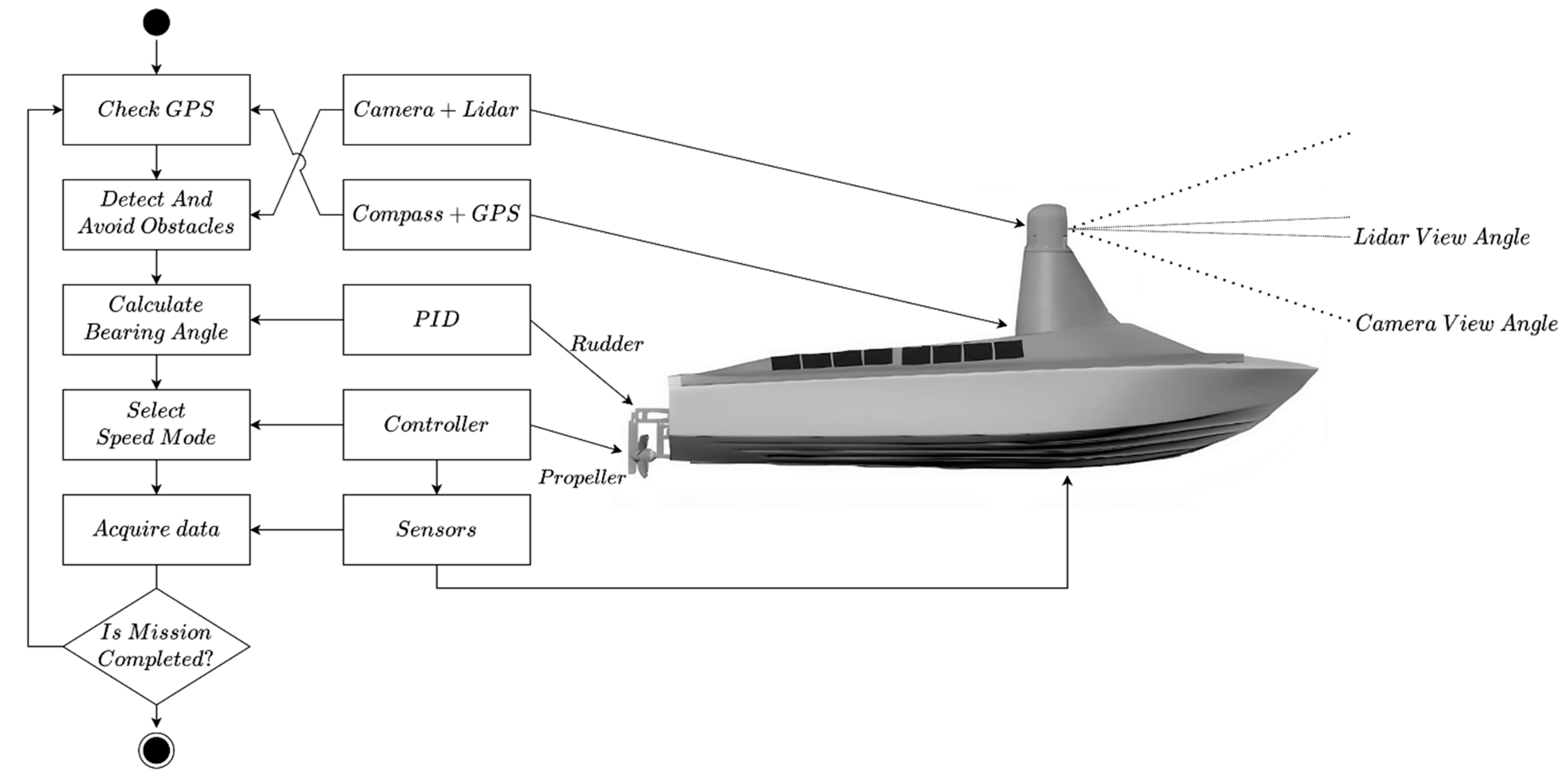
Figure 1 presents a general USV scheme showing the stages of the autonomous control program and the components involved at each stage.
The main program loop consists of 6 stages.
Stage 1: check the position of the USV using a navigation system consisting of a compass and GPS.
Stage 2: determining the presence of obstacles along the path of the USV and, if necessary, launching an obstacle avoidance program. A sensor subsystem equipped with LiDAR and a camera is used. The machine vision system is currently under development. The preliminary results were published in [
3].
Stage 3: determining whether it is required to make a turn. If necessary, the bearing angle is calculated, and with the PID controller fed with the difference between heading and bearing angles, the boat changes its direction.
Stage 4: rotation speed of the propeller is established. The speed is selected between three options. The first, maximal speed (up to 35 km/h) corresponds to the case when the boat is planning, which is necessary to cover large distances. The second, slower speed (8 km/h) is required for maneuvering and collecting information from sensors. Additionally, this speed is the most energy-efficient. The third speed (very slow) is intended for parking the boat.
Stage 5: if the boat is on a monitoring mission, it performs measurements and writes the results into the database, including current GPS coordinates. For supporting fish plants, such data are acquired as the level of oxygen dissolved in water, depth, temperature, salinity, and other water parameters. Again, an appropriate set of sensors is required onboard.
Stage 6: checking the end of the mission. If this condition is met, the boat stops. When it happens, the USV demands manual control of the operator, who, if needed, parks it, puts it on the charging station, takes the collected data, or transports the boat to another site.
With minor changes, this program can be used for unmanned cargo between different points of the coast. This is relevant, for example, in sparsely populated areas.
2.1.2. Hull and Onboard Equipment
The design of the hull is one of the most important stages of the creation of USVs because the hull determines the payload of the vessel and its dynamic characteristics.
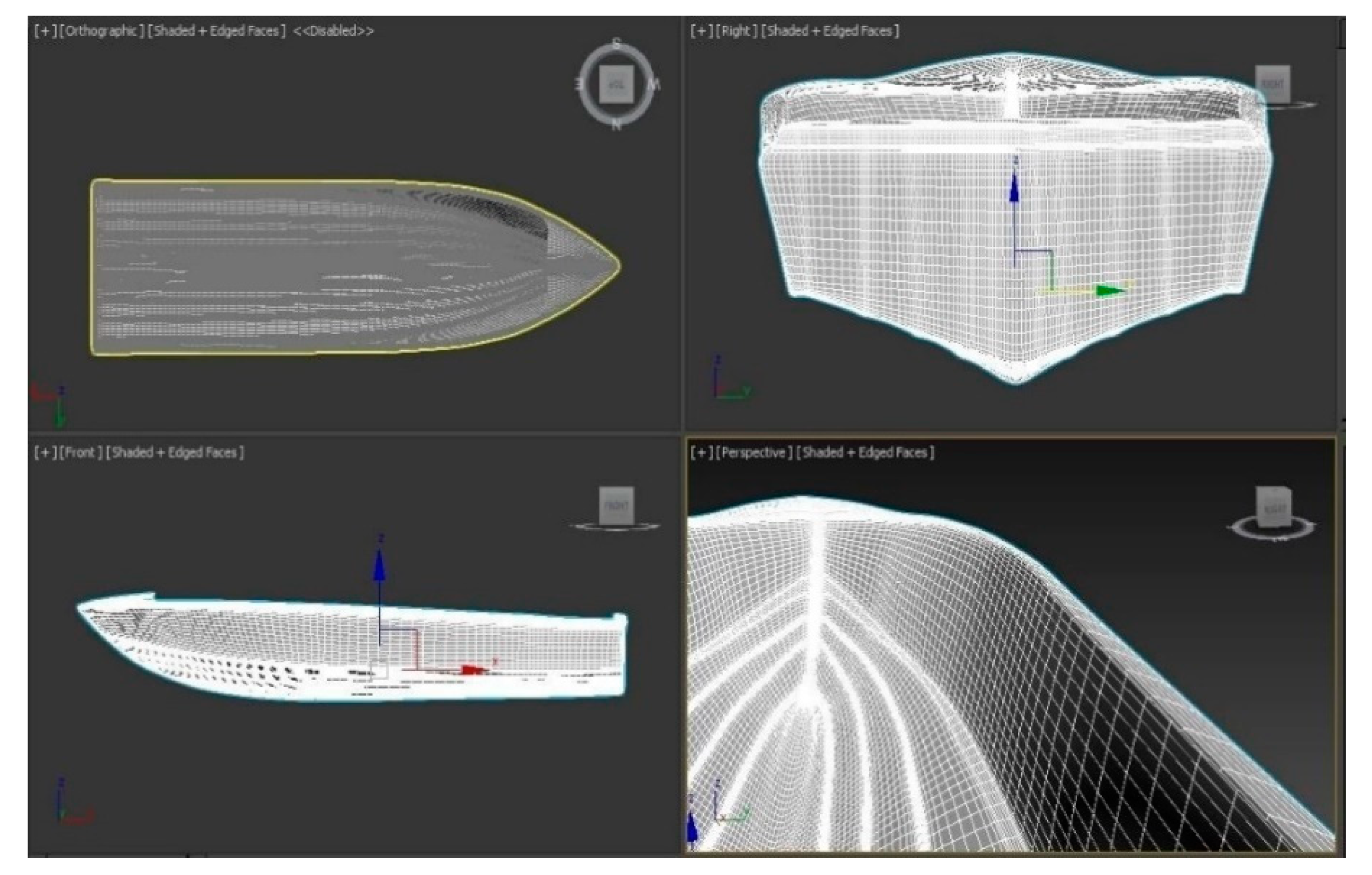
We decided to create a planning deep-V hull with an increased keel density of the bottom (
Figure 2) for our USV [
13]. This shape of the hull provides a comfortable ride on the waves with minimal loss of speed. Fiberglass was chosen as the material for the body, as the most accessible, light and repairable material.
The initial step of hull designing was creating a low-polygonal model of its half; then, this part was combined with the mirror copy. After that smoothing and increasing the polygonality of the model was to add, and the thickness of the hull board was set equal to 2 mm (
Figure 3).
Based on the developed three-dimensional model, fiberglass housing was created. The overall dimensions of the boat are 1200 × 400 × 400 mm. Next, we designed the optimal layout for USV.
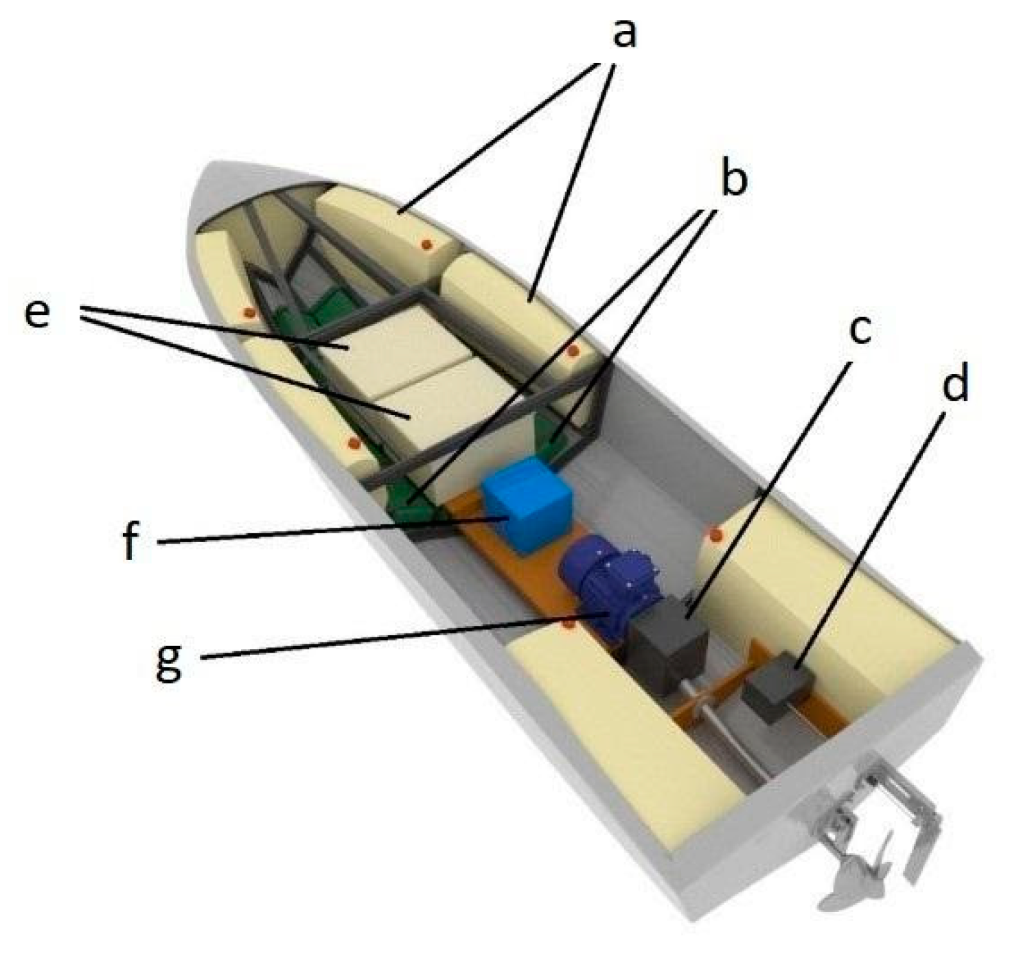
Figure 4 shows the 3D model of USV interiors.
Next, a boat cover was designed where solar panels, a tower with a sensor subsystem, and technical hatches for the maintenance issues are located.
For partial replenishment of the battery charge, the boat is equipped with flexible monocrystalline solar panels. The operating voltage of the solar panel is 18 V, and the current is 1.5 A with a total area of the solar cells of 0.15 square meters. Two lithium-polymer batteries with a full capacity of 40 Ah at a voltage of 14.8 V were installed as the primary energy sources. Hatches are hermetically sealed compartments, which are watertight if the boat is covered by a wave or overturned.
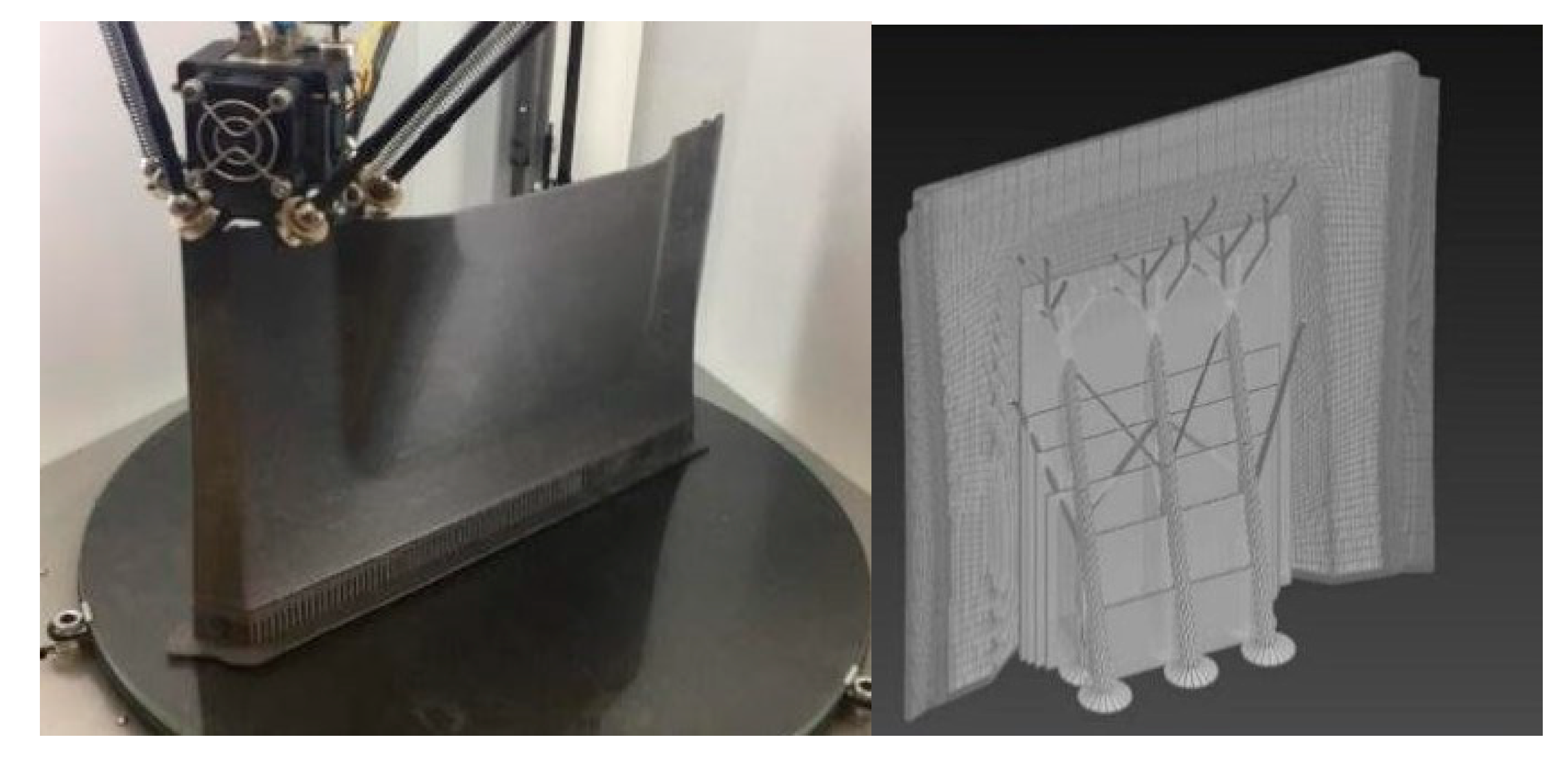
The glass-reinforced plastic body was created using 3D-printing technology. Overall hull cover appearance is shown in
Figure 5.
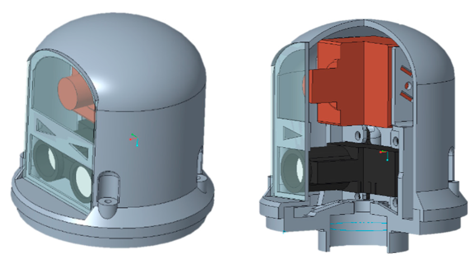
The sensor subsystem, located on the lid of the boat, consists of the camera, which internal controller processes video stream to detect obstacles, and Garmin LIDAR-Lite v2.0 rangefinder (
Figure 6).
The vessel top cover is made of ABS plastic using additive technologies. The back of the case cover is printed on a 3D printer made of ASA plastic. ASA (acrylonitrile styrene acrylate) is a sufficiently flexible and robust material that can withstand the stresses that arise during the operation of a crewless boat [
14].
The resulting 3D model of the assembled unmanned boat is shown in
Figure 7. The final step in creating the model was the placement of internal components inside the case. Batteries are located in the bow of the boat for even weight distribution. Additionally in the nose are compartments for the payload. The control electronics are distributed throughout the interior of the vessel and are housed in sealed cases.
Figure 8 presents the exterior of the developed USV.
The resulting hull design makes the boat unsinkable in the event of capsizing or being entirely covered by a wave. Due to the tightness of the top cover and the electronics compartments, the boat will continue to function.
2.2. Autonomus Steering System
2.2.1. Autopilot Model
To perform steering control of the boat in automatic mode we used a GPS sensor (Ublox NEO-7N) [
15] and a compass (hmc5883l) [
16] with an STM32F401 microcontroller.
Table 1 shows the characteristics of the GPS module Ublox NEO-7N.
Table 2 shows the characteristics of the compass module.
The GPS data for the points the boat should navigate is stored in SD flash memory up to 64 GB. Using a brushless motor (SEAKING 3660) and steering, the autopilot will correct the route to reach the next fix.
Figure 9 illustrates the process of autopilot correction.
2.2.2. Magnetometer Calibration
To increase the accuracy of the readings is necessary to calibrate the magnetometer [
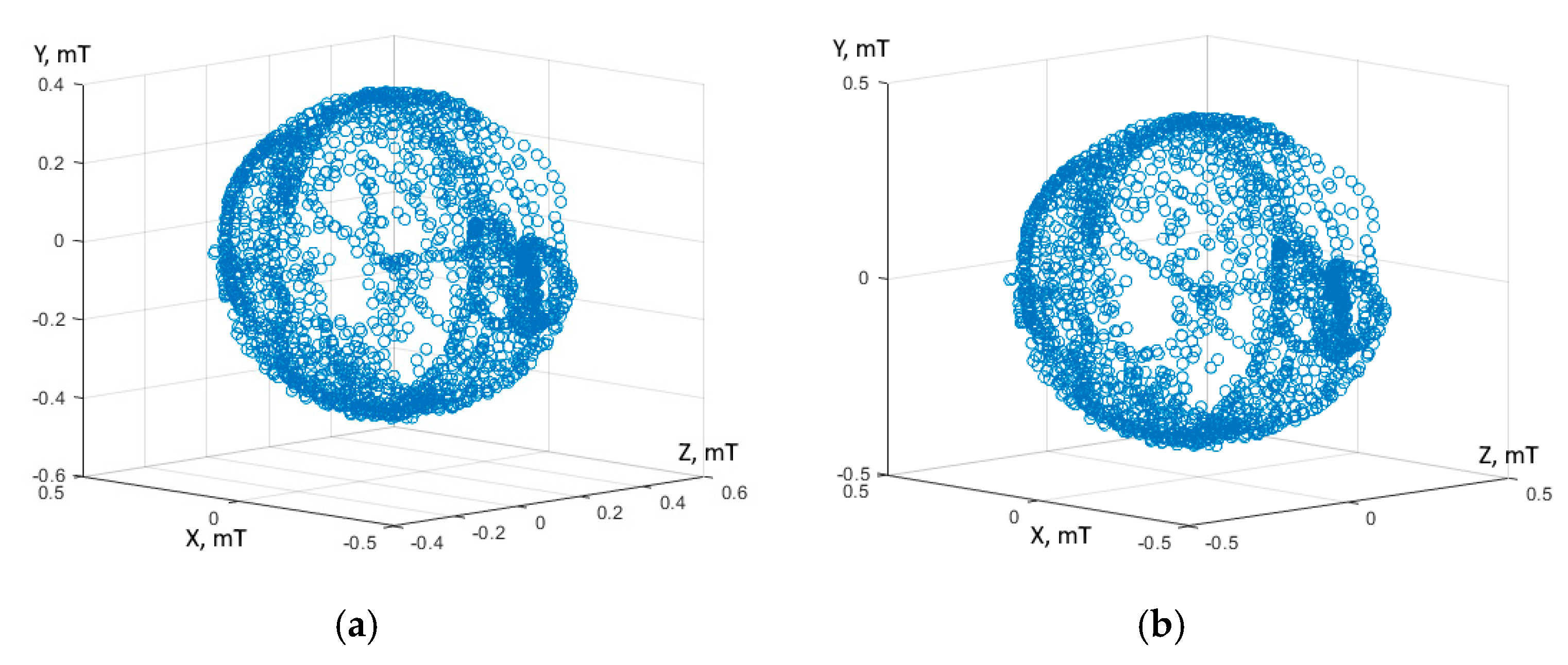
17] properly. We used the MATLAB package’s built-in magnetometer calibration function “magcal” to calibrate the magnetometer (
Figure 10). This function calculates the conversion and offset matrix from raw data. The processed data are calculated as follows:
where
is the column vector of the calibrated data,
is the correction matrix,
— is the source data column vector,
—is the zero offset column vector.
2.2.3. Distance Calculation
Using the latitude and longitude provided by the GPS sensor, the great-circle distance between the boat and the first checkpoint is calculated according to the Haversine formula, giving the shortest distance over the Earth’s surface [
18].
Equations (3)–(5) show the Haversine formula where is latitude, is longitude, is Earth radius, a is the square of half the length of the straight line between two points, is the distance traveled on the surface of the sphere in radians, and is the distance between the two points.
If the calculated distance does not exceed 2 m, the next checkpoint is used. This process continues until the boat passes all checkpoints set.
2.2.4. Calculating Bearing and Heading Angle
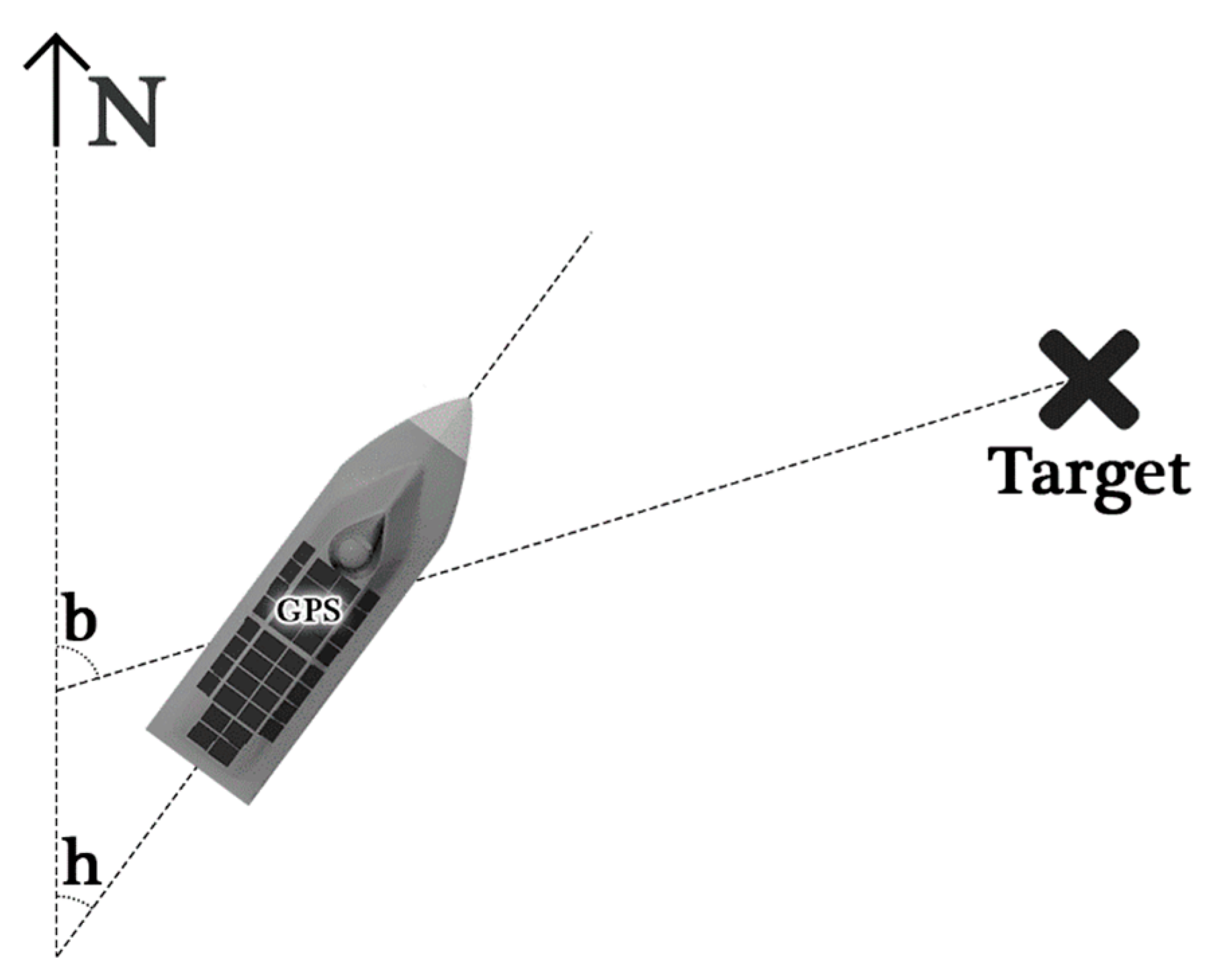
The bearing angle, as is shown in
Figure 11, is the angle between the straight line that passes through the target point and the direction to north [
19]. This angle is calculated using the GPS data read by the GPS sensor and the GPS data of the next target.
Heading angle is the angle between the boat’s direction and the north. This angle is calculated using the data provided by the magnetometer sensor.
Figure 11 shows this angle.
2.2.5. Calculating Bearing Angle
With the latitude (
) and the longitude (
) of the boat read from the GPS sensor, as well as the latitude (
) and the longitude (
) of the next target point read from the memory, the bearing angle can be calculated using (6)–(8):
where:
2.2.6. Calculating Heading Angle
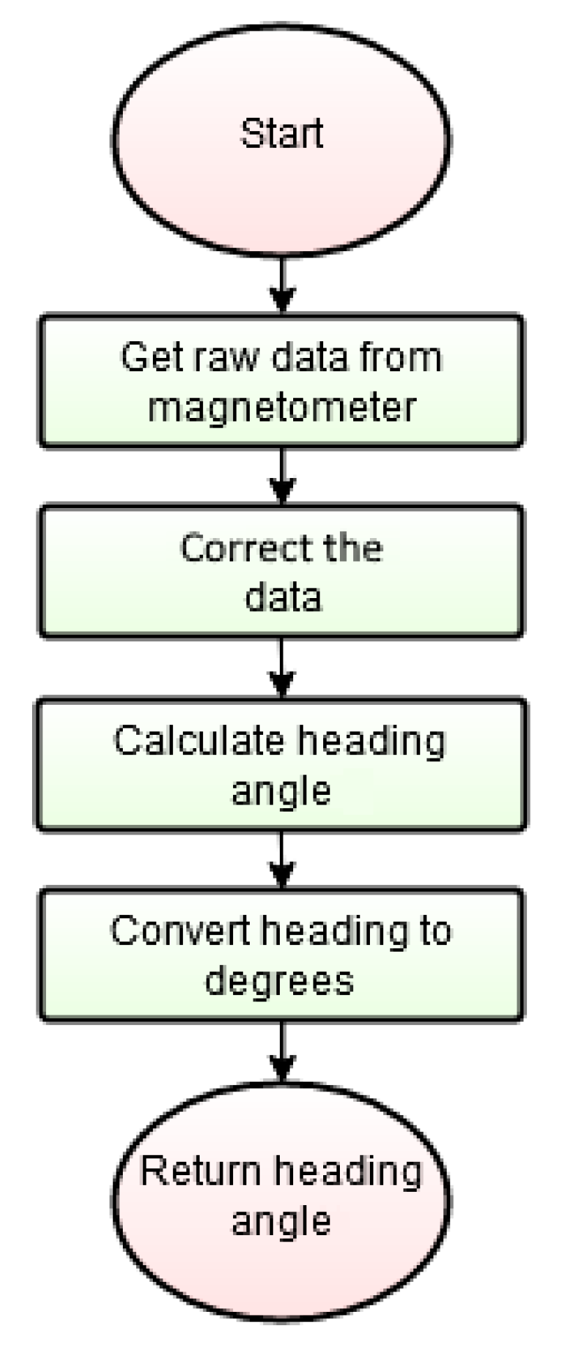
The heading angle is calculated based on the magnetometer data. The magnetometer provides data on the magnitude of magnetic induction relative to the three axes X, Y, and Z. These data are calibrated applying the transform matrix and the bias correction vector estimated before.
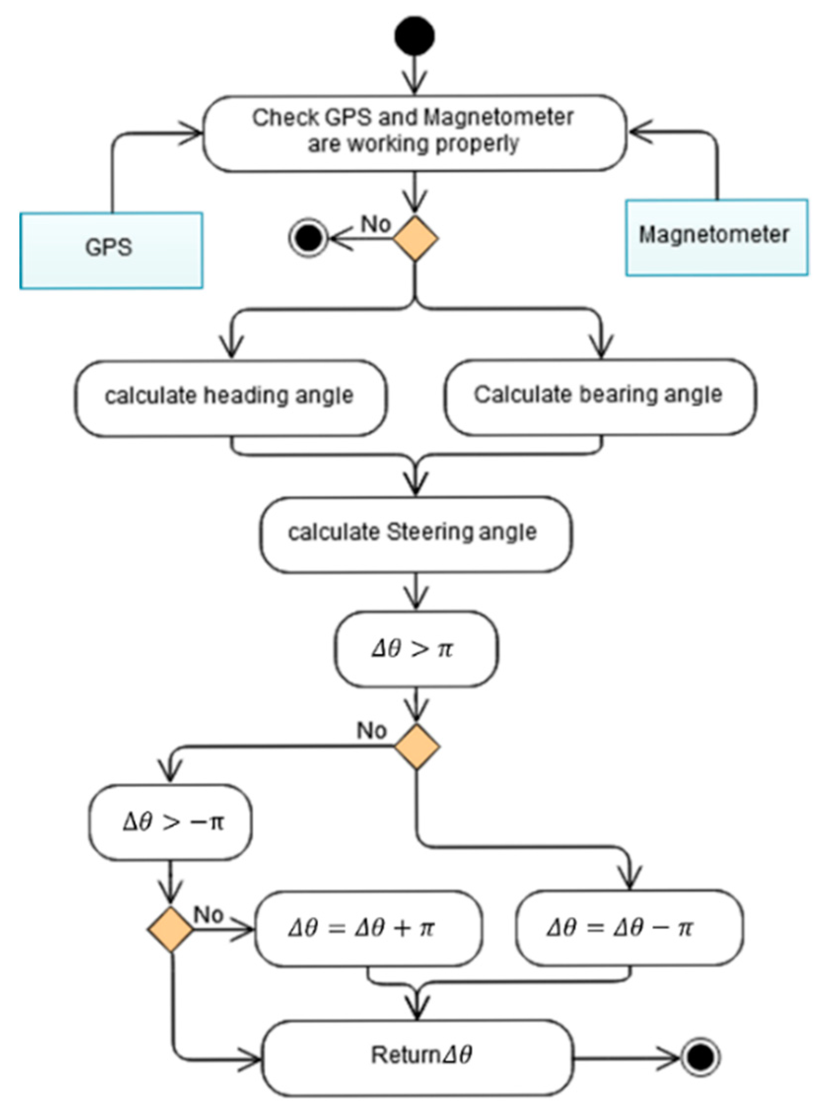
For simplicity, all angles were converted to degrees. The flowchart of the process is shown in
Figure 12.
It is important to determine the axes on which the angle measurement is made precisely. This fact necessitates placing the magnetometer away from any magnetic field source (e.g., motors) as the sensor is susceptible.
2.2.7. Steering Angle
The steering angle is the optimal (smallest) angle that the boat needs to cope with the direction to the target. We can calculate this angle as a difference between the heading angle and the bearing angle.
Taking into account (3)–(8), the resulting angle ranges from
to
. Since the change in the angle should not exceed 360 degrees, we normalize this value to the range from
to
. The algorithm is shown in
Figure 13.
2.2.8. Angular Error
The steering angle is calculated and corrected five times per second while the boat is moving to the waypoint. Moreover, the boat’s movement line is estimated according to the corresponding GPS data for each point. Let us call the angle it makes with the north the directing angle. The difference between this angle and the heading angle is called an angular error. The navigation system tends to correct the angular error; consequently, the boat would move to the target point. Correction of the angle is performed by the PID regulator, which is described below.
2.2.9. Steering Controller
A PID controller is used to handle the boat’s steering, where the goal is to make the error angle as less as possible. The pre-calculated steering angle is used as the feedforward of the controller. The simplicity of its synthesis defines the choice of its type. Controllers such as LQR, LQG [
20], and others could also be used. However, due to inaccurate mechanics and the need for accurate identification of model parameters, they would hardly improve the overall control system performance.
To tune the controller, the well-known Ziegler-Nichols tuning rule (“Z-N rule”), proposed in the classical work [
21], was used. This rule was introduced in the 1940s and had a notable impact on making PID feedback controls that earned acceptance and enthusiasm among the control engineers. At that time, PID was known but applied only reluctantly because of stability concerns. With the Ziegler-Nichols rule, engineers finally had a practical and systematic way of tuning PID loops for improved performance. Exploiting this heuristic tuning rule, it is possible to estimate proper values for the gains of a PID controller by measuring the actual system responses in some experiments. These three PID gain parameters are as follows:
—the controller path gain;
—the controller’s integrator time constant;
—the controller’s derivative time constant.
These three parameters are used to establish the input correction signal
from the error signal
according to formula:
Using (9) one can obtain the transfer function of the control system that shows the relationship between error and controller output:
Two feedback loop parameters are measured experimentally:
Because the study goal is to achieve the most precise regulation and thus reject disturbance of any kind, the tuning rules work pretty well when an analog controller is provided. In other words, to have a linear, monotonic, and sluggish system and a response that is dominated by a single-pole exponential “lag” or system that can be considered linear.
In the case of our experiment, the model does not have a perfect first-order lag characteristic, but our approximation is reasonable to describe the frequency response roll-off. The higher-order poles will introduce an extra phase shift, however. Even if they do not affect the shape of the gain roll-off much, the phase shift matters a lot to loop stability.
According to [
22], The Ziegler-Nichols rule transfer function can be presented as follows:
The parameter of the above mentioned model is the gain, which determines by dividing the ratio of output level to that of the input level at low frequencies.
The parameter α of the model is calculated by applying the frequency
at which the phase passes through
radians to the plant first-order lag terms. The inverse of this frequency is the period of the oscillation
.
To estimate the time delay parameter, first, we need to evaluate the phase shift of the lag stage by substituting
into the first-order lag model and then assign it to pure the time delay parameter [
22].
The final PID coefficients are as follows:
—15.12;
—5;
—10.96
3. Results
First, computer simulation of the control system was carried out according to well-known planar kinematics with 3 degrees of freedom (DOF) model presented in the literature, refer for example to [
23]. According to it, the USV motion equations are represented by three-dimensional sparse matrices. To avoid overloading the paper, the mathematical model of the boat kinematics is omitted.
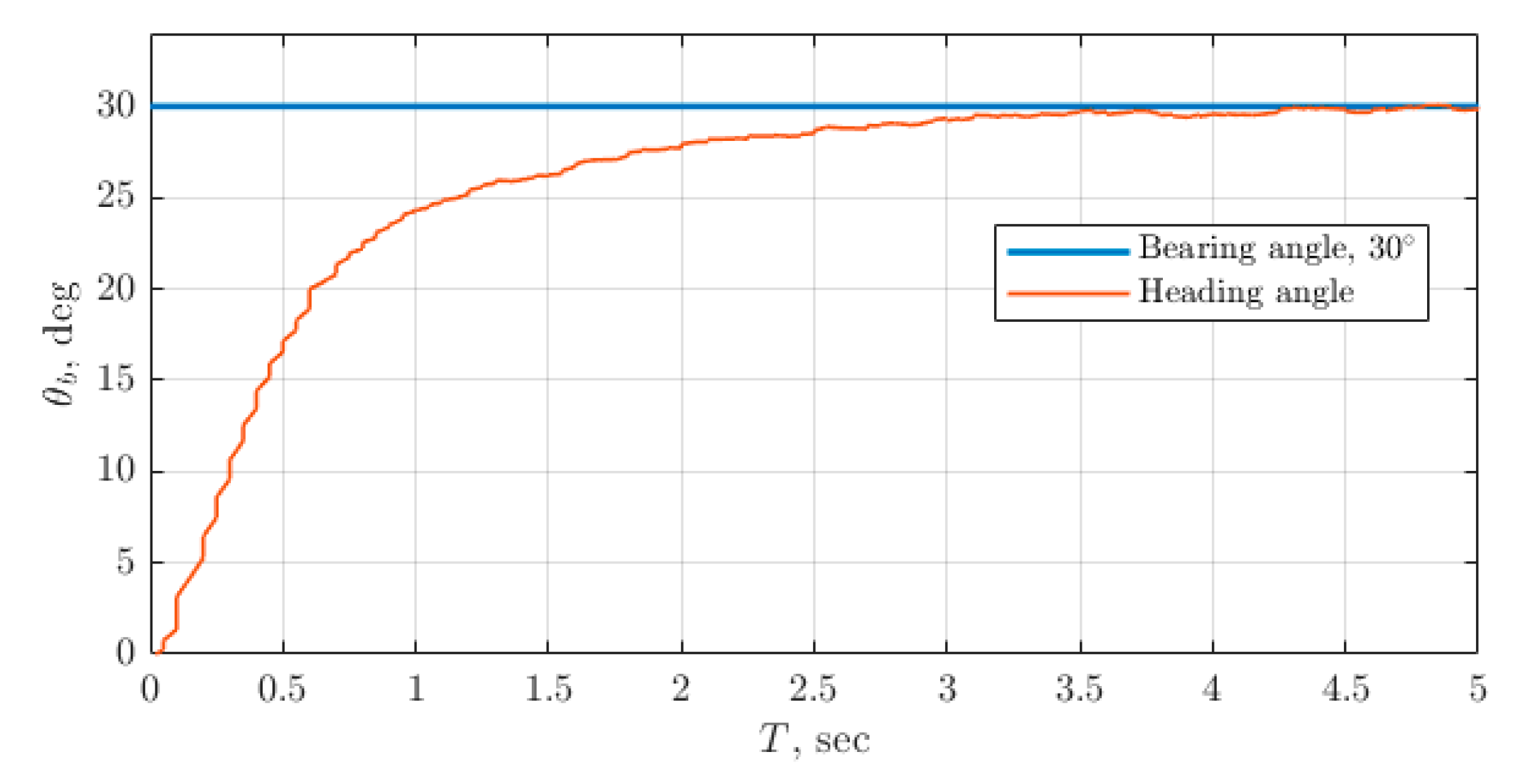
Figure 14 illustrates the simulated turn of USV with the designed controller in the presence of disturbance and uncertainty. Since we did not identify the USV precisely, which is a separate challenging task, the controller parameters were adjusted empirically during the experimental study.
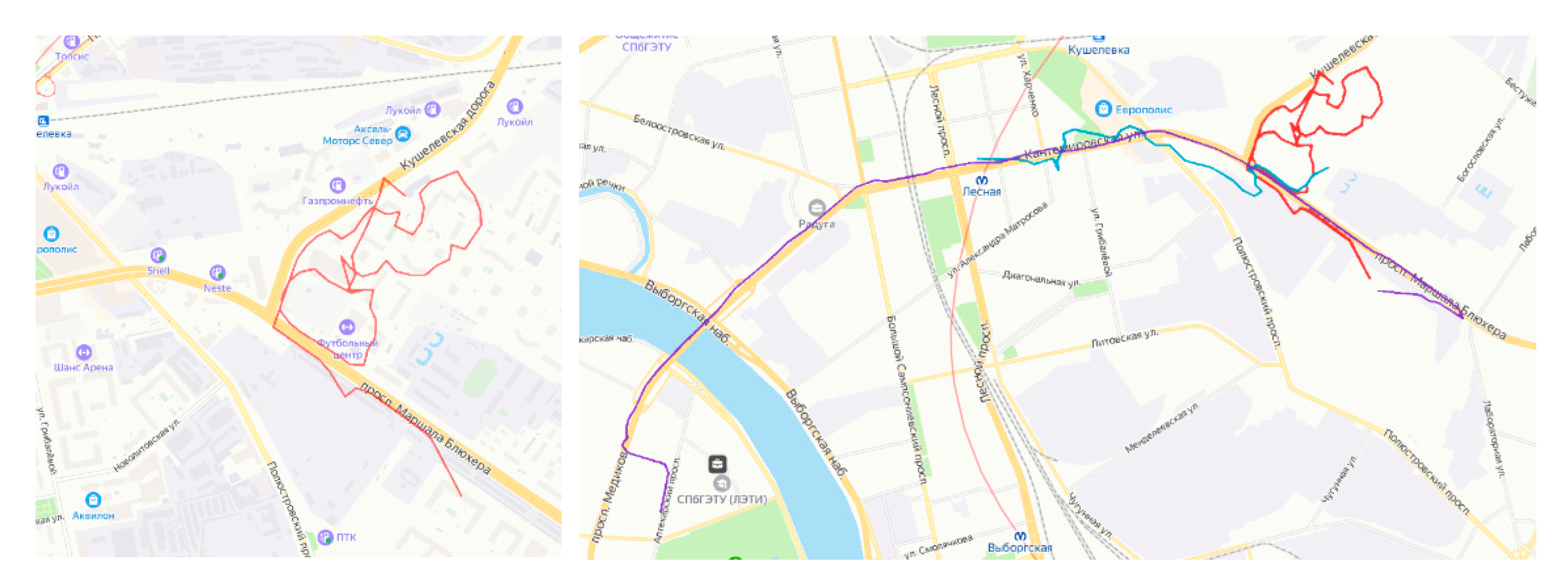
To calibrate the GPS sensor, it was necessary to create a test set of points to tune it. Calibration of the compass and GPS was carried out in the city since it is possible to compare the obtained values with the real coordinates with greater accuracy than on the water [
24]. Therefore a path was taken in the city and all GPS points were collected and mapped with the actual ones (
Figure 15). The city environment does not possess such interference as wind drift, rolling, and others that impede data processing on water.
To set control points and display the traversed path, the Google Earth program was used [
25,
26]. The data about the track is usually presented in the formats (.kmz), (.kml). A program was written to extract the coordinates in the data array for further work: identifying the coordinates in the file and formatting them for further use, etc.
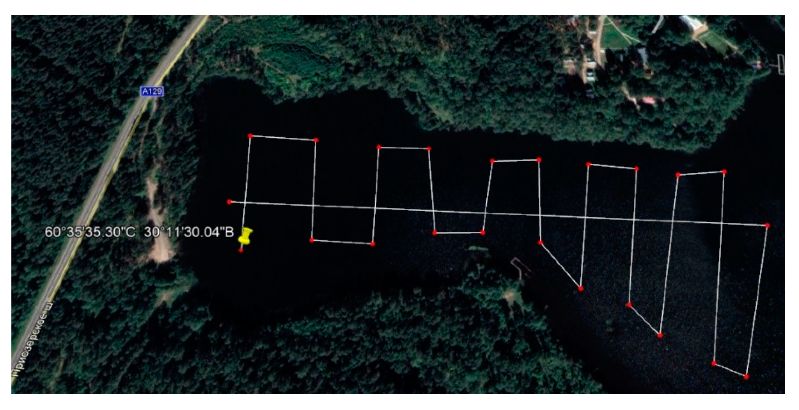
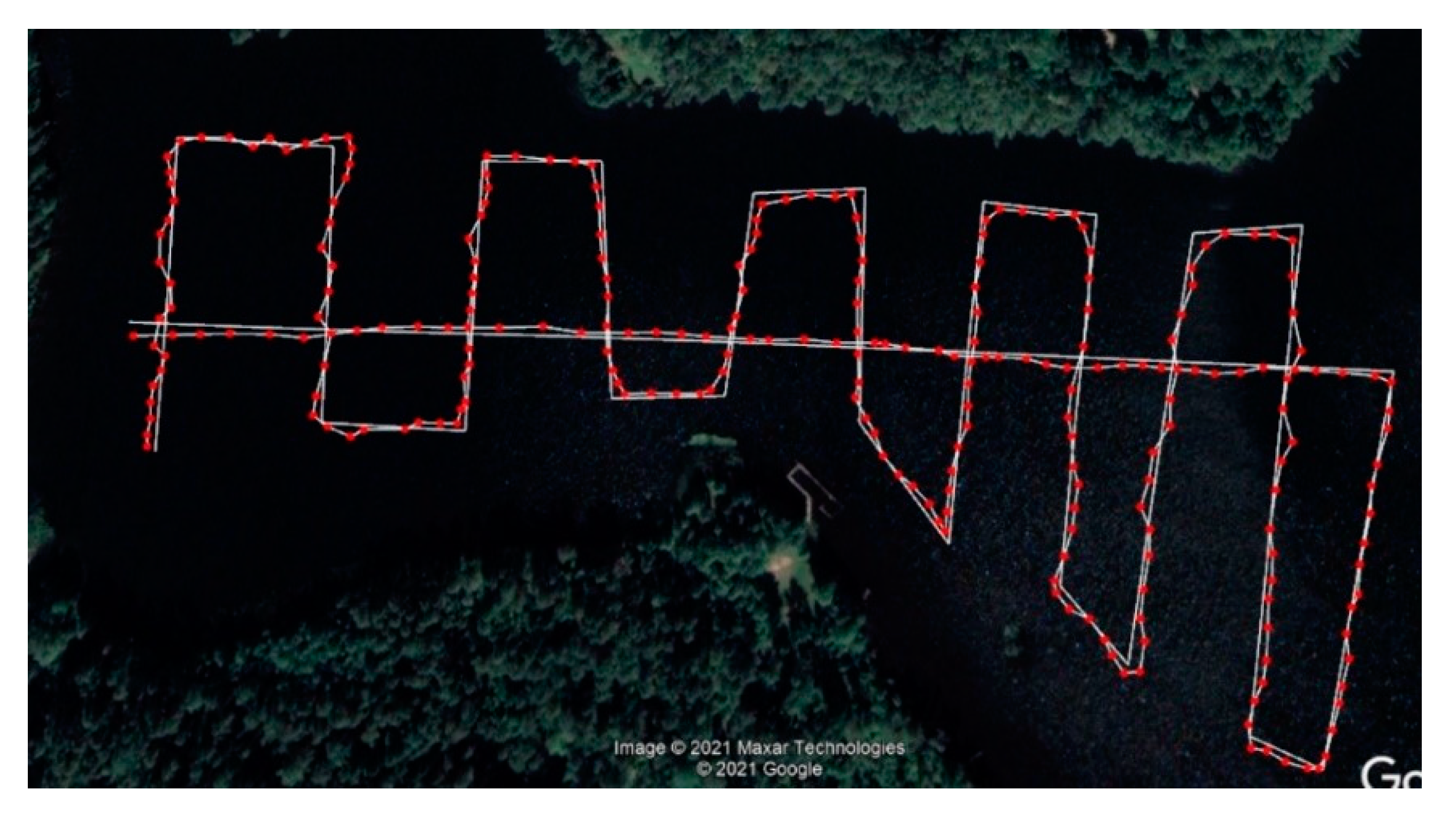
Tests were carried out on lake Ulovnoe in the Leningrad region of Russia. The designated route that the boat should follow is shown in
Figure 16.
Figure 17 shows the actual route passed by USV with the designed control system. The distance traveled by boat was 2.6 km. USV reached a maximum speed of 35 km/h on the first section of the route. After that, the boat’s speed was constantly set at 8 km/h under normal conditions for the rest of the course, which corresponds to the most optimal movement strategy for the described USV [
27]. The average error, calculated as the mean deviation from the set route points, appeared to be ±2.5 m. This correlates well with the typical error of satellite-based general-purpose navigation modules. Therefore, the developed system does not introduce additional errors exceeding the amount that can be absorbed by more generous GPS error.
However, we can see that with the same data logging time interval (5 s), the distance between the points of the covered path is different. This is due to external factors such as currents, wind drift, and waves on the water. These factors also determine the curvature of the line of movement between the control points of the given path. The time taken to complete the given course was 21 min.
4. Conclusions
This article is devoted to the design of the easy-to-do unmanned surface vehicle (USV) based on a 1.2-m fiberglass hull and cheap 32-bit controller aimed to environmental monitoring, cargo missions, fish farming support, and others. We propose a modular architecture for the USV controller and a navigation system. Moreover, this cheap, reproducible and robust design is available for students’ and small research groups, which makes it important for educational purposes as well.
We calibrated a GPS module with the control point method and achieved reasonable accuracy. Additionally, the boat was tested experimentally, and we found that its performance corresponds to our expectations. Numerical parameters of the developed USV are the following: self-weight is 8.5 kg, the payload is up to 12 kg; the maximum speed of the boat without cargo is 35 km/h; the most energy-efficient speed limit is 8 km/h. Battery life is up to 40 h in the energy-efficient mode. The maximum discrepancy of the GPS sensor with the given points was ±2.5 m during the tests.
In comparison with recent USVs of the similar size and monitoring purpose, such as ARC (Aberystwyth University, UK) and VECTOR (Federal Institute of Education, Science, and Technology of Ceara, Brazil), our robot has greater speed and maneuverability, which makes its missions faster, and also partially increases its resistance to wind and waves.
The advantages of the proposed design are:
High possible speed of missions in the water area;
Small dimensions, allowing the USV to be transported between separate water aquatics;
The ability to use the developed control and navigation system with different types of USVs, as well as its ease of calibration and suitability for long-range missions, since it takes into account the sphericity of the Earth;
The disadvantages are:
In further studies, we intend to provide a machine vision system to avoid obstacles and detect floating garbage, add sensors for environmental monitoring, and develop an algorithm for autonomous return of the boat to base and recharge.
Author Contributions
Conceptualization, G.K. and T.K.; data curation, S.N.T.B.; formal analysis, S.N.T.B.; investigation, G.K., V.R. and M.K.; methodology, T.K.; project administration, V.R. and T.K.; resources, S.N.T.B. and M.K.; software, G.K., V.R. and M.K.; supervision, T.K.; validation, G.K. and V.R.; visualization, G.K. and M.K.; writing—original draft, G.K. and S.N.T.B.; writing—review & editing, V.R. and T.K. All authors have read and agreed to the published version of the manuscript.
Funding
The paper has no external funding.
Data Availability Statement
Data sharing is not applicable to this article.
Conflicts of Interest
The authors declare no conflict of interest.
References
- Zaghloul, A.; Saber, M.; El-Dewany, C. Chemical indicators for pollution detection in terrestrial and aquatic ecosystems. Bull. Natl. Res. Cent. 2019, 43, 156. [Google Scholar] [CrossRef]
- Chen, Y.; Han, D. Water quality monitoring in smart city: A pilot project. Autom. Constr. 2018, 89, 307–316. [Google Scholar] [CrossRef] [Green Version]
- Kolev, G.; Solomevich, E.; Rodionova, E.; Kopets, E.; Rybin, V. Sensor subsystem design for small unmanned surface vehicle. IOP Conf. Ser. Mater. Sci. Eng. 2019, 630, 12022. [Google Scholar] [CrossRef]
- Randhawa, S.S.; Sandha, S.; Srivastava, B. A Multi-sensor Process for In-Situ Monitoring of Water Pollution in Rivers or Lakes for High-Resolution Quantitative and Qualitative Water Quality Data. In Proceedings of the 2016 IEEE International Conference on Computational Science and Engineering (CSE) and IEEE International Conference on Embedded and Ubiquitous Computing (EUC) and 15th Intl Symposium on Distributed Computing and Applications for Business Engineering (DCABES), Paris, France, 24–26 August 2016; pp. 122–129. [Google Scholar]
- Parameswari, M.; Moses, M.B. Online measurement of water quality and reporting system using prominent rule controller based on aqua care-IOT. Des. Autom. Embed. Syst. 2018, 22, 25–44. [Google Scholar] [CrossRef]
- Budiarti, R.P.N.; Tjahjono, A.; Hariadi, M.; Purnomo, M.H. Development of IoT for Automated Water Quality Monitoring System. In Proceedings of the 2019 International Conference on Computer Science, Information Technology, and Electrical Engineering (ICOMITEE), Jember, Indonesia, 16–17 October 2019; pp. 211–216. [Google Scholar]
- Yao, H.; Qin, R.; Chen, X. Unmanned aerial vehicle for remote sensing applications—A review. Remote. Sens. 2019, 11, 1443. [Google Scholar] [CrossRef] [Green Version]
- Kraaijenbrink, P.; Shea, J.; Litt, M.; Steiner, J.; Treichler, D.; Koch, I.; Immerzeel, W. Mapping surface temperatures on a debris-covered glacier with an unmanned aerial vehicle. Front. Earth Sci. 2018, 6, 64. [Google Scholar] [CrossRef] [Green Version]
- Sauzé, C.; Neal, M. Design considerations for sailing robots performing long term autonomous oceanography. Int. Robot. Sail. Conf. 2008, 6, 21–29. [Google Scholar]
- Melo, M.; Mota, F.; Albuquerque, V.; Alexandria, A. Development of a robotic airboat for online water quality monitoring in lakes. Robotics 2019, 8, 19. [Google Scholar] [CrossRef] [Green Version]
- Manley, J.E. New tools for ocean exploration, equipping the noaa ship okeanos explorer. In Proceedings of the OCEANS 2008, Quebec City, QC, Canada, 15–18 September 2008; pp. 1–5. [Google Scholar]
- Bertram, V. Unmanned surface vehicles—A survey. Ski. Selsk. 2008, 1, 1–14. [Google Scholar]
- Guan, G.; Wang, L.; Geng, J.; Zhuang, Z.; Yang, Q. Parametric automatic optimal design of USV hull form with respect to wave resistance and seakeeping. Ocean. Eng. 2021, 235, 109462. [Google Scholar] [CrossRef]
- Xiang, B.; Yin, X.; Zhang, J. A novel cool material: ASA (acrylonitrile-styrene-acrylate) matrix composites with solar reflective inorganic particles. Compos. Sci. Technol. 2017, 145, 149–156. [Google Scholar] [CrossRef]
- NEO-7N GPS Module Datasheet. Available online: http://surl.li/aqjqe (accessed on 10 November 2021).
- HMC5883L Kompass Module Datasheet. Available online: https://datasheetspdf.com/pdf-file/795537/Honeywell/HMC5883L/1 (accessed on 10 November 2021).
- Li, S.; Cheng, D.; Gao, Q.; Wang, Y.; Yue, L.; Wang, M.; Zhao, J. An Improved Calibration Method for the Misalignment Error of a Triaxial Magnetometer and Inertial Navigation System in a Three-Component Magnetic Survey System. Appl. Sci. 2020, 10, 6707. [Google Scholar] [CrossRef]
- Azdy, R.A.; Darnis, F. Use of Haversine Formula in Finding Distance between Temporary Shelter and Waste End Processing Sites. J. Phys. Conf. Ser. 2020, 1500, 012104. [Google Scholar] [CrossRef]
- Liao, X.; Chen, Z.; Gui, H.; Du, M. CFD Prediction of Ship Seakeeping and Slamming Behaviors of a Trimaran in Oblique Regular Waves. J. Mar. Sci. Eng. 2021, 9, 1151. [Google Scholar] [CrossRef]
- Sengupta, I.; Gupta, S.; Deb, D.; Ozana, S. Dynamic Stability of an Electric Monowheel System Using LQG-Based Adaptive Control. Appl. Sci. 2021, 11, 9766. [Google Scholar] [CrossRef]
- Ziegler, J.G.; Nichols, N.B. Optimum settings for automatic controllers. Trans. ASME 1993, 115, 220–222. [Google Scholar] [CrossRef]
- Ziegler-Nichols Tuning Rules for PID. Available online: https://www.mstarlabs.com/control/znrule.html (accessed on 12 November 2021).
- Sonnenburg, C.R.; Woolsey, C.A. Modeling, Identification, and Control of an Unmanned Surface Vehicle. J. Field Robot. 2013, 30, 371–398. [Google Scholar] [CrossRef] [Green Version]
- Upadhyay, J.; Abhishek, R.; Dipankar, D. Multiple Drone Navigation and Formation Using Selective Target Tracking-Based Computer Vision. Electronics 2021, 10, 2125. [Google Scholar] [CrossRef]
- Mohammed, N.Z.; Ghazi, A.; Mustafa, H.E. Positional accuracy testing of Google Earth. Int. J. Multidiscip. Sci. Eng. 2013, 4, 6–9. [Google Scholar]
- Upadhyay, J.; Rawat, A.; Deb, D.; Muresan, V.; Unguresan, M.L. An RSSI-based localization, path planning and computer vision-based decision making robotic system. Electronics 2020, 9, 1326. [Google Scholar] [CrossRef]
- Rybin, V.G.; Kolev, G.Y.; Karimov, T.I.; Ostrovskii, V.Y.; Druzhina, O.S.; Sigaeva, M.S. Estimating the Autonomy Range of the Battery-Powered Small Unmanned Surface Vehicle. In Proceedings of the 2020 Ural Smart Energy Conference (USEC), Ekaterinburg, Russia, 13–15 November 2020; Volume 4, pp. 9–12. [Google Scholar]
Figure 1.
Autonomous boat mission program and its parts responsible for the execution of program subroutines.
Figure 1.
Autonomous boat mission program and its parts responsible for the execution of program subroutines.
Figure 2.
Deep-V hull type.
Figure 2.
Deep-V hull type.
Figure 3.
Hull model after smoothing. Board is 2 mm thick.
Figure 3.
Hull model after smoothing. Board is 2 mm thick.
Figure 4.
The interior design of the vessel: (a) non-flooding compartments, (b) storage batteries, (c) gearbox, (d) steering gear, (e) sealed compartments with electronics, (f) motor control controller, (g) brushless electric motor.
Figure 4.
The interior design of the vessel: (a) non-flooding compartments, (b) storage batteries, (c) gearbox, (d) steering gear, (e) sealed compartments with electronics, (f) motor control controller, (g) brushless electric motor.
Figure 5.
Hull cover model after smoothing (right) and manufacturing process.
Figure 5.
Hull cover model after smoothing (right) and manufacturing process.
Figure 6.
The model of the sensor subsystem.
Figure 6.
The model of the sensor subsystem.
Figure 7.
3D model of the vessel.
Figure 7.
3D model of the vessel.
Figure 8.
The developed unmanned surface vehicle (USV) at an industrial exhibition.
Figure 8.
The developed unmanned surface vehicle (USV) at an industrial exhibition.
Figure 9.
Autopilot diagram.
Figure 9.
Autopilot diagram.
Figure 10.
Comparing (a,b), one can see that uncalibrated data are in the (−0.6; 0.4) and (−0.4; 0.6) range on two axes, indicating a slight offset from the center. The calibrated data from the magnetometer on all axes is in the range from −0.5 to 0.5 on all axes.
Figure 10.
Comparing (a,b), one can see that uncalibrated data are in the (−0.6; 0.4) and (−0.4; 0.6) range on two axes, indicating a slight offset from the center. The calibrated data from the magnetometer on all axes is in the range from −0.5 to 0.5 on all axes.
Figure 11.
Illustration of bearing and heading angles calculation, where b stands for bearing angle and h stands for heading angle.
Figure 11.
Illustration of bearing and heading angles calculation, where b stands for bearing angle and h stands for heading angle.
Figure 12.
Heading angle calculation.
Figure 12.
Heading angle calculation.
Figure 13.
Steering angle calculation diagram.
Figure 13.
Steering angle calculation diagram.
Figure 14.
USV simulation results with disturbance and uncertainty.
Figure 14.
USV simulation results with disturbance and uncertainty.
Figure 15.
The paths are taken to generate data needed for GPS calibration.
Figure 15.
The paths are taken to generate data needed for GPS calibration.
Figure 16.
Specified route.
Figure 16.
Specified route.
Figure 17.
Distance traveled data.
Figure 17.
Distance traveled data.
Table 1.
Ublox NEO-7N specification.
Table 1.
Ublox NEO-7N specification.
| Parameter | Specification |
|---|
| Operating temperature | −40–85 °C |
| Velocity accuracy | 0.1 m/s |
| Heading accuracy | 0.5 degrees |
| Autonomous horizontal position accuracy | 2.5 m |
| SBAS horizontal position accuracy | 2.0 m |
| Sensitivity Tracking and Navigation | −162 dBm |
| Operational limit dynamics | ≤4 g |
Table 2.
Compass hmc5883l specification.
Table 2.
Compass hmc5883l specification.
| Parameter | Conditions | Specification |
|---|
| Digital Resolution | VDD = 3.0 V, 12-bit ADC | 00.73–4.35 milli-gauss |
| Sensitivity (Gain) | VDD = 3.0 V, 12-bit ADC | 230–1370 LSb/gauss |
| Operating temperature | - | −30–85 °C |
| Field Range | Full scale | −8–8 gauss |
| Sensitivity Tempco | TA = −40 to 125 °C, Uncompensated Output | −0.3%/°C |
| Publisher’s Note: MDPI stays neutral with regard to jurisdictional claims in published maps and institutional affiliations. |
© 2021 by the authors. Licensee MDPI, Basel, Switzerland. This article is an open access article distributed under the terms and conditions of the Creative Commons Attribution (CC BY) license (https://creativecommons.org/licenses/by/4.0/).
