Design of a Wide-Band Microstrip Filtering Antenna with Modified Shaped Slots and SIR Structure

 ,
, 
 , ,
, ,  , and
, and 
Abstract
1. Introduction
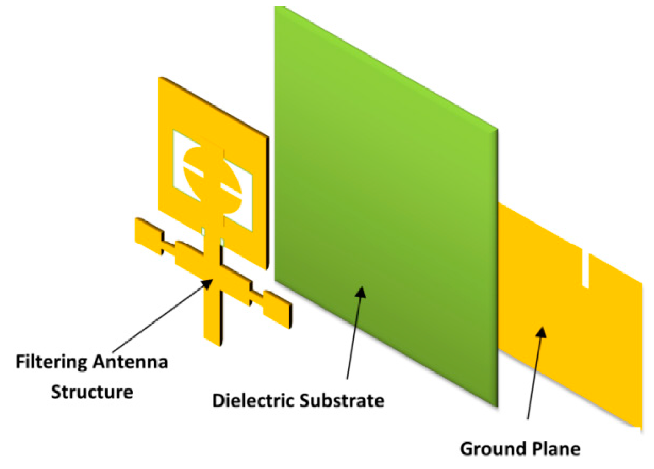
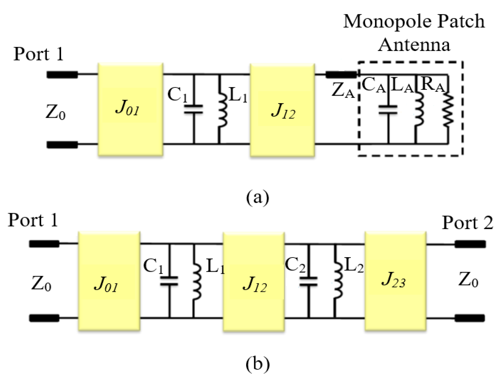
2. Design of the Filtering Antenna
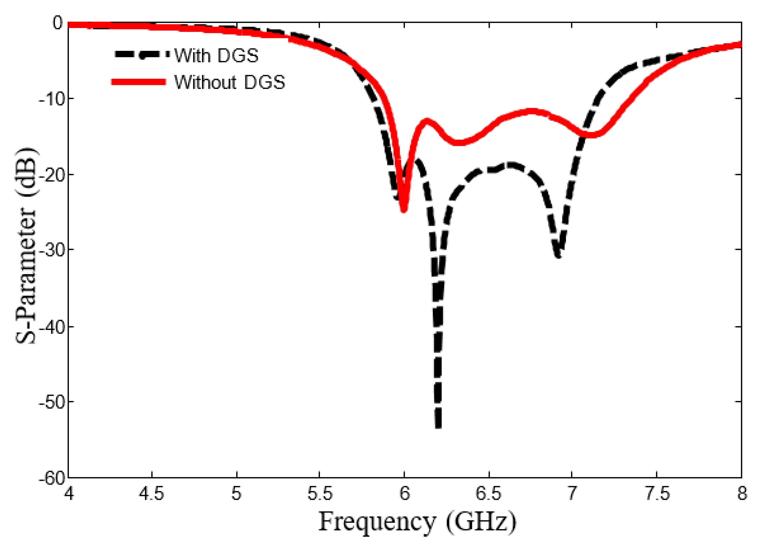
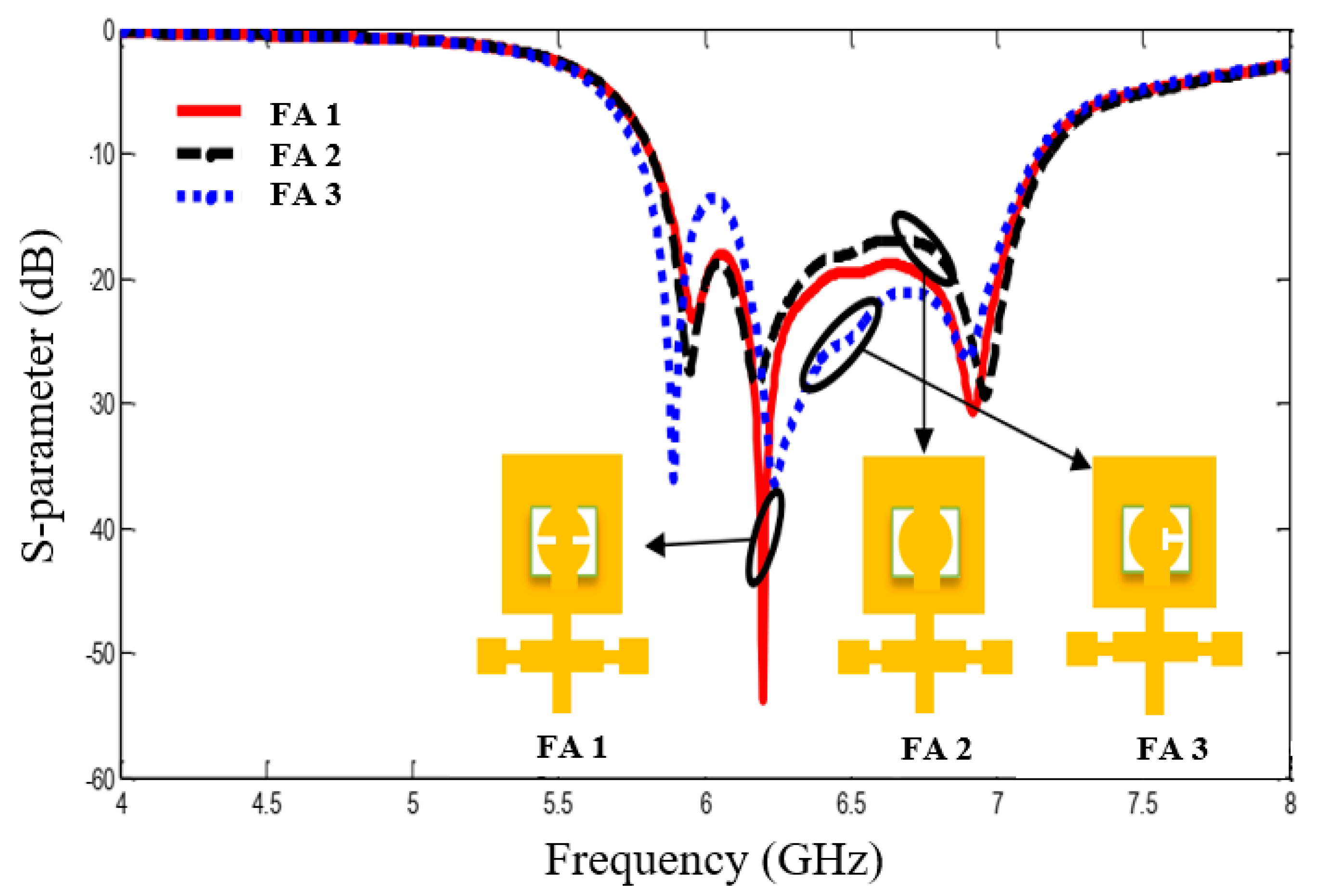
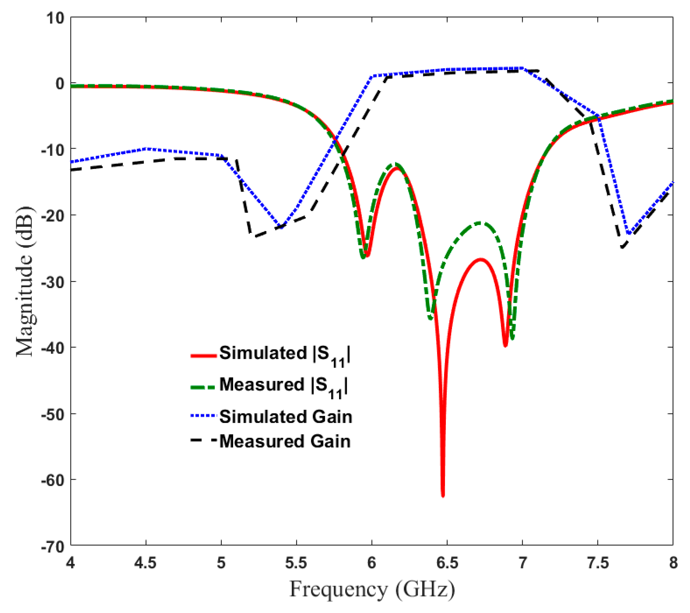
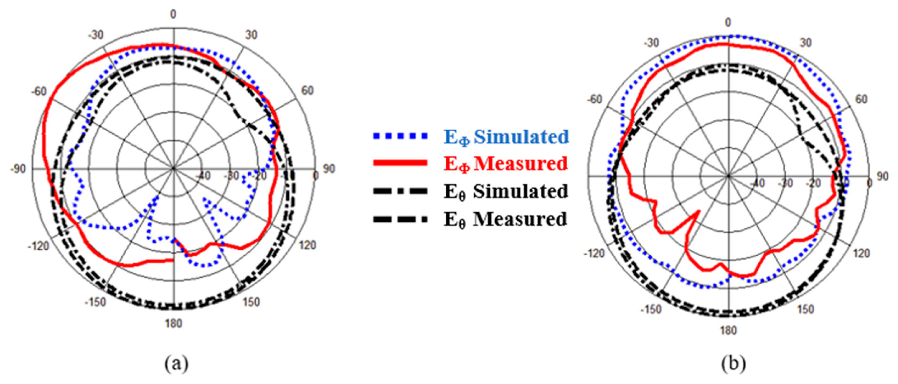
3. Simulation and Measurement Results and Discussion
4. Conclusions
Author Contributions
Funding
Acknowledgments
Conflicts of Interest
References
- Hussaini, A.; Al-Yasir, Y.I.A.; Voudouris, K.; Mohammed, B.; Abd-Alhameed, R.; Mohammed, H.; Elfergani, I.; Abdullah, A.; Makris, D.; Rodriguez, J.; et al. Green Flexible RF for 5G. In Fundamentals of 5G Mobile Networks, 1st ed.; Rodriguez, J., Ed.; John Wiley and Sons: Hoboken, NJ, USA, 2015. [Google Scholar]
- Al-Yasir, Y.; Abdullah, A.; Ojaroudi Parchin, N.; Abd-Alhameed, R.; Noras, J. A New Polarization-Reconfigurable Antenna for 5G Applications. Electronics 2018, 7, 293. [Google Scholar] [CrossRef]
- Liu, H.W.; Ren, B.P.; Li, S.; Guan, X.H.; Wen, P.; Peng, X.X.Y. High-Temperature Superconducting Bandpass Filter Using Asymmetric Stepped-Impedance Resonators with Wide-Stopband Performance. IEEE Trans. Appl. Supercond. 2015, 25, 1–6. [Google Scholar]
- Al-Yasir, Y.I.A.; Parchin, N.O.; Abdulkhaleq, A.; Abd-Alhameed, R.; Noras, J. Recent Progress in the Design of 4G/5G Reconfigurable Filters. Electronics 2019, 8, 114. [Google Scholar] [CrossRef]
- Abdulraheem, Y.I.; Abdullah, A.; Mohammed, H.; Abd-Alhameed, R.; Noras, J. Design of Frequency-reconfigurable Multiband Compact Antenna using two PIN diodes for WLAN/WiMAX Applications. IET Microw. Antennas Propag. 2017, 11, 1098–1105. [Google Scholar] [CrossRef]
- Mohammed, H.J.; Abdulsalam, F.; Abdulla, A.S.; Ali, R.S.; Abd-Alhameed, R.A.; Noras, J.M.; Abdulraheem, Y.I.; Ali, A.; Rodriguez, J.; Abdalla, A.M. Evaluation of genetic algorithms, particle swarm optimisation, and firefly algorithms in antenna design. In Proceedings of the 13th International Conference on Synthesis, Modeling, Analysis and Simulation Methods and Applications to Circuit Design (SMACD), Lisbon, Portugal, 27–30 June 2016; pp. 1–4. [Google Scholar]
- Al-Yasir, Y.; Abd-Alhameed, R.A.; Noras, J.M.; Abdulkhaleq, A.M.; Parchin, N.O. Design of very compact combline band-pass filter for 5G applications. In Proceedings of the Loughborough Antennas & Propagation Conference (LAPC 2018), Loughborough, UK, 12–13 November 2018; pp. 1–4. [Google Scholar]
- Abdel-Jabbar, H.; Kadhim, A.S.; Saleh, A.L.; Al-Yasir, Y.I.A.; Parchin, N.O.; Abd-Alhameed, R.A. Design and optimization of microstrip filtering antenna with modified shaped slots and SIR filter to improve the impedance bandwidth. TELKOMNIKA Telecommun. Comput. Electron. Contro 2020, 18, 515–545. [Google Scholar] [CrossRef]
- Al-Yasir, Y.I.A.; Tu, Y.; Parchin, N.O.; Elfergani, I.; Abd-Alhameed, R.; Rodriguez, J.; Noras, J. Mixed-coupling multi-function quint-wideband asymmetric stepped impedance resonator filter. Microw. Opt. Tech. Lett. 2019, 61, 1181–1184. [Google Scholar] [CrossRef]
- Mabrok, M.; Zahriladha, Z.; Masrukin, E.; Sutikno, T.; Othman, A.R.; Nurhasniza, E. Switchable Dual-band Bandpass Filter Based on Stepped Impedance Resonator with U-Shaped Defected Microstrip Structure for Wireless Applications. TELKOMNIKA Telecommun. Comput. Electron. Control 2019, 17, 1032–1039. [Google Scholar] [CrossRef]
- Al-Yasir, Y.I.A.; Tu, Y.; Bakr, M.S.; Parchin, N.O.; Asharaa, A.S.; Mshwat, W.A.; Abd-Alhameed, R.A.; Noras, J.M. Design of multi-standard single/tri/quint-wideband asymmetric stepped-impedance resonator filters with adjustable TZs. IET Microw. Antennas Propag. 2019, 13, 1637–1645. [Google Scholar] [CrossRef]
- Al-Yasir, Y.I.A.; Tu, Y.; Parchin, N.O.; Abdulkhaleq, A.; Kosha, J.; Ullah, A.; Abd-Alhameed, R.; Noras, J. New Multi-standard Dual-Wideband and Quad-Wideband Asymmetric Step Impedance Resonator Filters with Wide Stop Band Restriction. Int. J. RF Microw. Comput. Aided Eng. 2019, 29, 1–17. [Google Scholar] [CrossRef]
- Al-Yasir, Y.I.A.; Parchin, N.O.; Alabdallah, A.; Abdulkhaleq, A.M.; Abd-Alhameed, R.A.; Noras, J.M. Design of Bandpass Tunable Filter for Green Flexible RF for 5G. In Proceedings of the 2019 IEEE 2nd 5G World Forum (5GWF), Dresden, Germany, 30 September–2 October 2019; pp. 194–198. [Google Scholar]
- Mohsen, M.K.; Isa, M.S.M.; Isa, A.A.M.; Abdulhameed, M.K. Enhancement of boresight radiation for leaky wave antenna array. TELKOMNIKA Telecommun. Comput. Electron. Control 2019, 17, 2179–2185. [Google Scholar] [CrossRef]
- Al-Yasir, Y.I.A.; Parchin, N.O.; Alabdallah, A.; Abdulkhaleq, A.M.; Sajedin, M.; Elfergani, I.T.E.; Abd-Alhameed, R.A. Design, Simulation and Implementation of Very Compact Open-loop Trisection BPF for 5G Communications. In Proceedings of the 2019 IEEE 2nd 5G World Forum (5GWF), Dresden, Germany, 30 September–2 October 2019; pp. 189–193. [Google Scholar]
- Al-Yasir, Y.; OjaroudiParchin, N.; Abdulkhaleq, A.; Hameed, K.; Al-Sadoon, M.; Abd-Alhameed, R. Design, Simulation and Implementation of Very Compact Dual-band Microstrip Bandpass Filter for 4G and 5G Applications. In Proceedings of the 2019 16th International Conference on Synthesis, Modeling, Analysis and Simulation Methods and Applications to Circuit Design (SMACD), Lausanne, Switzerland, 15–18 July 2019; pp. 41–44. [Google Scholar]
- Al-Yasir, Y.I.A.A.; JaroudiParchin, N.O.; Alabdullah, A.; Mshwat, W.; Ullah, A.; Abd-Alhameed, R. New Pattern Reconfigurable Circular Disk Antenna Using Two PIN Diodes for WiMax/WiFi (IEEE 802.11 a) Applications. In Proceedings of the 2019 16th International Conference on Synthesis, Modeling, Analysis and Simulation Methods and Applications to Circuit Design (SMACD), Lausanne, Switzerland, 15–18 July 2019; pp. 53–56. [Google Scholar]
- Jain, A.; Agrawal, A. Design and Optimization of a Microstrip Patch Antenna for Increased Bandwidth. Int. J. Electr. Comput. Energetic Electron. Commun. Eng. 2013, 7, 191–195. [Google Scholar]
- Kumar, R.; Dhubkarya, D. Design and analysis of circular ring microstrip antenna. Glob. J. Res. Eng. 2011, 11, 1–5. [Google Scholar]
- Paul, L.C.; Sultan, N. Design, simulation and performance analysis of a line feed rectangular micro-strip patch antenna. Int. J. Eng. Sci. Emerg. Technol. 2013, 4, 117–126. [Google Scholar]
- Boualleg, A.; Merabtine, N. Analysis of radiation patterns of rectangular microstrip antennas with the uniform substrate. Semicond. Phys. Quantum Electron. Optoelectron. 2005, 8, 88–91. [Google Scholar] [CrossRef]
- Liu, H.-W.; Ku, C.-H.; Yang, C.-F. Novel CPW-fed planar monopole antenna for WiMAX/WLAN applications. IEEE Antennas Wirel. Propag. Lett. 2010, 9, 240–243. [Google Scholar] [CrossRef]
- Naeem, U.; Bila, S.; Verdeyme, S.; Thévenot, M.; Monédière, T. A compact dual band filter-antenna subsystem for 802. In 11 Wi-Fi applications. In Proceedings of the Wireless Technology Conference (EuWIT), 2010 European, Paris, France, 27–28 September 2010; pp. 181–184. [Google Scholar]
- Zuo, J.; Chen, X.; Han, G.; Li, L.; Zhang, W. An integrated approach to RF antenna-filter co-design. IEEE Antennas Wirel. Propag. Lett. 2009, 8, 141–144. [Google Scholar]
- Hong, J.-S.G.; Lancaster, M.J. Microstrip Filters for RF/Microwave Applications; John Wiley & Sons: Hoboken, NJ, USA, 2004; pp. 1–476. [Google Scholar]
- Stutzman, L.W.; Thiele, G.A. Antenna Theory and Design; John Wiley & Sons: Hoboken, NJ, USA, 2012; pp. 1–848. [Google Scholar]
- Chen, L.; Luo, Y.-L. Compact filtering antenna using CRLH resonator and defected ground structure. Electron. Lett. 2014, 50, 496–1498. [Google Scholar] [CrossRef]
- Kozlov, M.; Turner, R. A comparison of Ansoft HFSS and CST microwave studio simulation software for multi-channel coil design and SAR estimation at 7T MRI. Piers Online 2010, 6, 395–399. [Google Scholar] [CrossRef]
- Chuang, C.-T.; Chung, S.-J. A new compact filtering antenna using defected ground resonator. In Proceedings of the Microwave Conference Proceedings (APMC), Asia-Pacific, Yokohama, Japan, 7–10 December 2010; pp. 1003–1006. [Google Scholar]
- Al-Yasir, Y.I.A.; Abdullah, A.S.; Mohammed, H.J.; Mohammed, B.; Abd-Alhameed, R.A.; Noras, J. Design of Radiation Pattern-Reconfigurable 60-GHz Antenna for 5G Applications. J. Telecommun. 2014, 27, 7–11. [Google Scholar]
- Jadhav, J.B.; Deore, P.J. Filtering antenna with radiation and filtering functions for wireless applications. J. Electr. Syst. Inf. Technol. 2017, 4, 125–134. [Google Scholar] [CrossRef]
- Wang, K.; Zheng, L.-S.; Wong, S.W.; Zheng, Y.-F.; Chu, Q.-X. Design of even-order symmetric bandpass filter with Chebyshev response. Prog. Electromagn. Res. 2013, 42, 239–251. [Google Scholar] [CrossRef][Green Version]
- Mahmud, F.S.; Razalli, M.S.; Rahim, H.A.; Hoon, W.F.; Ilyas, M.Z. Parametric studies on effects of defected ground structure (DGS) for dual band bandstop microstrip filter. EPJ Web Conf. 2017, 162, 1–5. [Google Scholar] [CrossRef]
- Marotkar, P.; Kapur Zade, V. To Study the Effect of DGS on Antenna Parameters. Int. J. Ind. Electron. Electr. Eng. 2015, 3, 17–20. [Google Scholar]
- Wu, W.; Fan, R.; Wang, J.; Zhang, Q. A broadband low profile microstrip filter-antenna with an omni-directional pattern. In Proceedings of the 2014 3rd Asia-Pacific Conference on Antennas and Propagation, Harbin, China, 26–29 July 2014; pp. 580–582. [Google Scholar]
- Lin, C.-K.; Chung, S.-J. A Compact Filtering Microstrip Antenna with Quasi-Elliptic Broadside Antenna Gain Response. IEEE Antennas Wirel. Propag. Lett. 2011, 10, 381–384. [Google Scholar]
- Wu, W.; Ma, B.; Wang, J.; Wang, C. Design of a microstrip antenna with filtering characteristics for wireless communication systems. In Proceedings of the 2017 Sixth Asia-Pacific Conference on Antennas and Propagation (APCAP), Xi’an, China, 16–19 October 2017; pp. 1–3. [Google Scholar]
- Wu, W.; Yin, Y.; Zuo, S.; Zhang, Z.; Xie, J. A New Compact Filter-Antenna for Modern Wireless Communication Systems. IEEE Antennas Wirel. Propag. Lett. 2011, 10, 1131–1134. [Google Scholar]
- Ohira, M.; Ma, Z. An efficient design method of microstrip filtering antenna suitable for circuit synthesis theory of microwave bandpass filters. In Proceedings of the 2015 International Symposium on Antennas and Propagation (ISAP), Hobart, Australia, 9–12 November 2015; pp. 1–4. [Google Scholar]
- Al-Yasir, Y.I.A.; Hasanain, A.H.A.; Baha, A.S.; Parchin, N.O.; Ahmed, M.A.; Abdulkareem, S.A.; Raed, A.A. New Radiation Pattern-Reconfigurable 60-GHz Antenna for 5G Communications. IntechOpen 2019. Available online: https://www.intechopen.com/online-first/new-radiation-pattern-reconfigurable-60-ghz-antenna-for-5g-communications (accessed on 26 September 2019). [CrossRef]
- Al-Yasir, Y.I.A.; Parchin, N.O.; Elfergani, I.; Abd-Alhameed, R.A.; Noras, J.M.; Rodriguez, J.; Al-jzari, A.; Hammed, W.I. A New Polarization-Reconfigurable Antenna for 5G Wireless Communications. In Broadband Communications, Networks, and Systems. BROADNETS 2018. Lecture Notes of the Institute for Computer Sciences, Social Informatics and Telecommunications Engineering; Sucasas, V., Mantas, G., Althunibat, S., Eds.; Springer: Cham, Germany, 2019; Volume 263. [Google Scholar]
- Mohammed, K.A.; Alhamadani, A.; Al-Yasir, Y.I.A.; Saleh, A.L.; Parchin, N.O.; Abd-Alhameed, R. Study on the effect of the substrate material type and thickness on the performance of the filtering antenna design. TELKOMNIKA Telecommun. Comput. Electron. Control 2020, 18, 72–79. [Google Scholar]
- Al-Yasir, Y.I.A.; Ojaroudi Parchin, N.; Fares, M.N.; Abdulkahaleq, A.; Bakr, M.; Al-Sadoon, M.; Kosha, J.; Abd-Alhameed, R. A Differential-Fed Dual-Polarized High-Gain Filtering Antenna Based on SIW Technology for 5G Applications. In Proceedings of the 2020 14th European Conference on Antennas and Propagation (EuCAP), Copenhagen, Denmark, 15–20 March 2020; pp. 1–5. [Google Scholar]
- Al-Yasir, Y.I.A.; Ojaroudi Parchin, N.; Fares, M.n.; Abdulkhaleq, A.; Sajedin, M.; Elfergani, I.; Rodriguez, J.; Abd-Alhameed, R. New High-Gain Differential-Fed Dual-Polarized Filtering Microstrip Antenna for 5G Applications. In Proceedings of the 2020 14th European Conference on Antennas and Propagation (EuCAP), Copenhagen, Denmark, 15–20 March 2020; pp. 1–5. [Google Scholar]


| Parameter | W1 | W2 | W3 | W4 | W5 | W6 | W7 | W8 | W9 | W10 |
|---|---|---|---|---|---|---|---|---|---|---|
| Dimensions | 16 | 2.6 | 2.6 | 6.8 | 3.7 | 4 | 2 | 2.5 | 24 | 1.5 |
| Parameter | W11 | L1 | L2 | L3 | L4 | L5 | L6 | L7 | Ws | Ls |
| Dimensions | 1.5 | 16.5 | 8 | 4 | 6.5 | 5 | 23 | 6.5 | 28 | 30 |
| Parameter | Value |
|---|---|
| 0.257 | |
| 1 | |
| 1.4029 | |
| 0.7071 | |
| g3 | 1.9841 |
© 2020 by the authors. Licensee MDPI, Basel, Switzerland. This article is an open access article distributed under the terms and conditions of the Creative Commons Attribution (CC BY) license (http://creativecommons.org/licenses/by/4.0/).
Share and Cite
Al-Yasir, Y.I.A.; A. Alhamadani, H.; Kadhim, A.S.; Ojaroudi Parchin, N.; Saleh, A.L.; Elfergani, I.T.E.; Rodriguez, J.; Abd-Alhameed, R.A. Design of a Wide-Band Microstrip Filtering Antenna with Modified Shaped Slots and SIR Structure. Inventions 2020, 5, 11. https://doi.org/10.3390/inventions5010011
Al-Yasir YIA, A. Alhamadani H, Kadhim AS, Ojaroudi Parchin N, Saleh AL, Elfergani ITE, Rodriguez J, Abd-Alhameed RA. Design of a Wide-Band Microstrip Filtering Antenna with Modified Shaped Slots and SIR Structure. Inventions. 2020; 5(1):11. https://doi.org/10.3390/inventions5010011
Chicago/Turabian StyleAl-Yasir, Yasir I. A., Hana’a A. Alhamadani, Ahmed S. Kadhim, Naser Ojaroudi Parchin, Ameer L. Saleh, Issa T. E. Elfergani, Jonathan Rodriguez, and Raed A. Abd-Alhameed. 2020. "Design of a Wide-Band Microstrip Filtering Antenna with Modified Shaped Slots and SIR Structure" Inventions 5, no. 1: 11. https://doi.org/10.3390/inventions5010011
APA StyleAl-Yasir, Y. I. A., A. Alhamadani, H., Kadhim, A. S., Ojaroudi Parchin, N., Saleh, A. L., Elfergani, I. T. E., Rodriguez, J., & Abd-Alhameed, R. A. (2020). Design of a Wide-Band Microstrip Filtering Antenna with Modified Shaped Slots and SIR Structure. Inventions, 5(1), 11. https://doi.org/10.3390/inventions5010011