Review

X-Ray and UV Detection Using Synthetic Single Crystal Diamond

by
Maurizio Angelone
1,*,
Francesca Bombarda
1,
Silvia Cesaroni
2,
Marco Marinelli
1,
Angelo Maria Raso
1,
Claudio Verona
1 and
Gianluca Verona-Rinati
1
1
Industrial Engineering Department, Tor Vergata University of Rome, Via del Politecnico 1, 00133 Rome, Italy
2
Nuclear Department, ENEA CR Frascati, via E. Fermi 45, 00044 Frascati, Italy
*
Author to whom correspondence should be addressed.
Instruments 2025, 9(2), 9; https://doi.org/10.3390/instruments9020009
Submission received: 6 March 2025 / Revised: 2 April 2025 / Accepted: 4 April 2025 / Published: 11 April 2025

Abstract

:
Diamond is a semiconductor with a large band gap (5.48 eV), high carrier mobility (the highest for holes), high electrical resistance and low capacitance. Thanks to its outstanding properties, diamond-based detectors offer several advantages, among others: high signal-to-noise ratio, fast response, intrinsic pulse-shape discrimination capabilities for distinguishing different types of radiation, as well as operation in pulse and current modes. The mentioned properties meet most of the demanding requests that a radiation detection material must fulfil. Diamond detectors are suited for detecting almost all types of ionizing radiation including X-ray and UV photons, resulting also in blindness to visible photons and are used in a wide range of applications including ones requiring the capability to withstand harsh environments. After reviewing the fundamental physical properties of synthetic single crystal diamond (SCD) grown by microwave plasma enhanced chemical vapor deposition (MWPECVD) technique and the basic principles of diamond-photon interactions and detection, the paper focuses on SCD detectors developed for X-ray and UV detection, discussing their configurations, construction techniques, advantages, and drawbacks. Applications ranging from X-ray detection around accelerators to UV detection for fusion plasmas are addressed, and future trends are highlighted too.

1. Introduction

The excellent optical and infrared properties of diamond and its X-ray transparency coupled to other outstanding properties such as its excellent semiconductor properties, mechanical and radiation hardness, high thermal conductivity as well as chemical inertness and singular strength, have long made this material attractive for scientific and technological use in the field of optical, infra-red (IR), UV and X-ray detection in a large range of applications including the ones in harsh environments [1,2,3,4,5]. Indeed, diamond’s properties are already outlined by the root word for diamond which is the Greek term “αδαµα (adama)”, meaning unconquerable and indestructible.
The diamond properties meet most of the demanding requests that a radiation detection material must fulfil. Thanks to their outstanding properties, diamond detectors feature several advantages, among others: low noise, fast response, high radiation hardness, operation at high temperature, capability to discriminate among different types of radiation by intrinsic pulse-shape discrimination properties [6,7,8,9] as well as capability to operate both in pulse and current mode. Last, but not least, the low atomic number of diamond (Z = 6), close to that of human tissue, renders diamond very interesting and largely used in radiation dosimetry and microdosimetry [10,11,12,13].
The interest in using natural diamond as radiation detector dates back to 1941, i.e., the beginning of the nuclear era [14]. The earliest applications of natural diamond concerned its photoconductivity [15] in which the physics underlying the use of natural diamond as a radiation detector was observed. Natural diamond generated by geological process is monocrystalline, but impurities are always present inside its lattice, of which the most important being Nitrogen. Impurities form optical defects that modify the electronic properties of diamond. Four different species of natural diamond are classified depending upon the amount of Nitrogen, namely [1]: Type 1a (the most common diamond, 98% of the total); Type 1b, Type 2a, and Type 2b. The one suitable for radiation detection is Type 2a because the negligible content of Nitrogen allows for excellent electronic performances and transmission of UV radiation. However, despite the advantages discussed above, natural diamond resulted scarcely utilized for radiation detection owing to its scarce availability and very high cost.
In the last decades, thanks to the development of proper growing techniques, artificial diamond plates of excellent quality became available. The most effective method is the microwave plasma enhanced chemical vapor deposition (MWPECVD) technique [1,2,16,17,18]. Using this method, first polycristalline diamond (p-CVD) and, after the year 2000, single crystal diamond (SCD) have been produced and made available on the market. The SCD monocrystalline structure presents far superior performances as a radiation detector with respect to p-CVD, resulting in the most largely used to this purpose [7]. Since artificial SCD diamonds are suited for detecting almost all types of direct and indirect ionizing radiation over a very wide range of energy, detectors were realized and used for a large number of applications encompassing neutrons, charged particles and gammas detection and dosimetry, as well as X-ray and UV detection [19,20,21]. Notably, they have played a crucial role in the development of innovative detectors for high energy physics [22,23,24].
Diamond is transparent to electromagnetic radiation over a wide spectral range (from 180 nm to 100 µm); thus, it can play an exceptional role in optical technology. It is very important to detect the UV/X-ray bands for various scientific and technological applications like UV astronomy, plasma diagnostic, resin cleaning, combustion engineering, water purification, flame detection, biological effects and many more applications. Synthetic diamond could be applied to realize windows for IR thermal imaging for ‘dual band’ (Visible/IR) systems as well as in applications such as mirrors for high-power lasers or optical windows/monitors for X-ray synchrotron radiation. SCD of high purity with high integrity of crystalline structure is also an excellent candidate as a monochromator in X-ray optics [25].
The UV and X-ray region (UV/X) of the electromagnetic (EM) spectrum was paid increasing interest since the beginning of the 19th century, and a variety of UV/X detectors have been developed, mainly Silicon–based and photomultipliers. These devices have significant disadvantages: low quantum efficiencies, need filters to stop low energy photons (e.g., visible and infrared light), while photomultipliers require external high voltage supply. Aerospace and automotive industries, as well as various research activities (e.g., plasma diagnostic, accelerators, free electron lasers (FEL), space and astrophysics), have continuously proposed and solicited the development of fringe technologies tolerant also to harsh environments (chemical corrosion, high temperatures and hostile radiation environment, etc.). As a result, the main efforts are now directed toward a new generation of UV/X detectors fabricated from wide band-gap semiconductors [26,27], the most promising of which is diamond. The need of reliable UV and X-ray detectors is a relevant issue, e.g., in X-ray dosimetry [28,29], UV/X-ray astrophysics [30], and in fusion plasma experiments for detecting both X-ray and UV radiation emitted by the plasma [31]. In the case of fusion plasmas, diamond detectors are also used to measure neutrons emitted by the fusion reactions [22] and, together with X-ray and UV artificial SCD detectors, have proven to work properly on the JET [31,32] and FTU [33] fusion tokamaks.
This paper focuses mainly on synthetic single crystal diamond (SCD) detectors for (soft) X-ray and UV detection. After reviewing the fundamental physical properties of SCD diamond, different types of synthetic diamond-based radiation detectors developed for X-ray and UV detection are presented, discussing their physical properties and the realization techniques as well as advantages and drawbacks. A selection of applications and results is reported and, eventually, an overview of possible future developments is also addressed.
This work follows the one already published by MDPI Editor which was mostly dealing with SCD detectors for neutron detection and included a discussion about the behavior of diamond detectors operated at high temperature [9]. The present paper does not discuss all the details related to the physics of diamond already reported in the previous review and to which the reader is referred to along with the other excellent papers and reviews referenced on it.
Following [9], also in this paper the term “film” will be used to indicate diamond of up to few micron thickness, while the term “layer” will be used in all the cases in which the thickness is not defined or not important for the sake of the discussion. The term “plate” will mean thickness of several tens of microns.
After the Introduction, in Section 2 the paper presents a survey of basic diamond properties, while in Section 3 the basic principles of diamond-radiation interaction are reviewed. In Section 4, the principle of operation of photodetectors is recalled, while in Section 5, diamond photodetectors are introduced and discussed with some details. Section 6 deals with a selection of applications of diamond photodetectors to various research fields. Eventually, Section 7 discusses some of the open issues for diamond photodiodes and highlights some possible future developments and applications.

2. Survey of Diamond Properties

Diamond is the metastable allotropic form of carbon, characterized by a sp3 hybridization resulting in a 3D configuration. The sp3 hybridization implies that diamond atoms are arranged in a crystal structure (lattice) with bases of two atoms in which each carbon atom has four nearest neighbors. This is the typical face-centered-cubic (fcc) cell structure with eight atoms per unit cell (fcc tetrahedral arrangement). The nearest neighbor distance is b = 1.54 Å, and the unit cell dimension, at 298 K, is a = 3.567 Å. Diamond has the highest atomic density of any material in the earth (1.77 × 10²³ atoms/cm3), and its density, at 298 K, is 3.515 g/cm3 [2,3]. The lattice exhibits very strong bonding.
In natural diamond, carbon is present in two isotopes: 12C (98.9%) and 13C (1.1%). The stable phase of carbon is graphite which has a planar sp2 hybridization. For this reason, if diamond is strongly perturbed, it transforms into the stable phase graphite (the reverse is not possible). This phase transition can be attained in several ways (e.g., by heating diamond in an inert atmosphere), and the onset of graphitization is observed already at 1800 K. The rate of graphitization increases with temperature.
Diamond is also highly chemically inert, with two exceptions. First, at high temperatures, it is susceptible to oxidizing agents (e.g., oxygen, for T > 900 K). Second, still at high temperature, certain metals (e.g., iron, cobalt, manganese, nickel, chromium, and platinum) can act as solvents for carbon, leading to chemical bonding with diamond. This property is sometimes used for depositing electrical contacts on diamond detectors (see Section 5).
This paper focuses on the homoepitaxial or single crystal diamond (SCD). As discussed in the Introduction, the MWPECVD technique [1,2,34] results in the most suited method for producing high quality SCD diamond plates because it allows for p-CVD or SCD growth depending upon the growing substrate used. Typically, a p-Si substrate is used for producing polycrystalline CVD, and SCD diamond of low quality (e.g., grown by high temperature and high pressure (HTHP-type [18,35])) is used for growing high purity SCD-diamond. The MWPECVD techniques requires the use of high purity CH4 and H2 gases to avoid contamination and inclusion of impurities in the produced diamond. The high purity diamond produced by MWPECVD technique and used for detectors fabrication is also called “electronic grade” diamond to indicate its excellent electronics performances. Usually, the most important doping material in electronic grade diamond is Boron (p-type diamond) present in amount of a few ppb. Larger amounts of Boron can significantly alter electronics performance, and sometimes Boron is added to one side of the grown diamond layer to meet specific needs, such as creating an ohmic contact (see Section 5.2). Since discussing diamond growing techniques is beyond the scope of this paper, readers are referred to the specialized literature for further details, see for example [36,37].
Diamond, Silicon (Si) and Germanium (Ge), all belonging to group IV-A of the periodic table of elements, share the property of being semiconductors. They have crystalline lattice with allowed energy bands for electrons, the so-called valence and conduction bands, respectively, separated by an energy gap Eg (Figure 1). Diamond with Eg = 5.48 eV shows the highest Eg value compared to Si (Eg = 1.12 eV) and Ge (Eg = 0.67 eV) [38]. As it is known, the Eg value affects the electronic performances, as it is responsible for the higher or lower magnitude of the dark current of the detector at room temperature. The wide band gap together with its strong chemical bonding, which reflects in the high displacement energy (Ed) of carbon atoms in diamond lattice (Ed = 43.3 eV, [39]), allows diamond to exhibit good radiation tolerance as well as capability to operate at high temperature. The latter property depends not only on Eg but also on the high thermal conductivity (σT) of diamond (21.9 Wcm−1K−1), the highest among the natural elements. It is worth mentioning that most of the properties of diamond depend on the working temperature and, when applicable, on the external electrical field (e.g., carrier mobility). Table 1 summarizes some of the mentioned physical properties of natural diamond at different temperatures [2,3].
In diamond, at room temperature (300 K), electrons remain in the valence band bound to the outer atomic shells of the carbon atoms forming the lattice. When external energy is supplied, such as an increase in temperature, external radiation, etc., electrons (e) can be promoted to the conduction band. A vacancy (or hole, h+) is produced in the valence band and e/h pairs (EHP) are formed. Under the influence of an external electrical field, these EHP pairs (also called charge carriers) move in opposite directions, generating a current.

3. Diamond-Radiation Interactions

As previously mentioned, diamond can detect neutrons, photons and charged particles. Regardless of the type of radiation impinging on the diamond, the interaction radiation-diamond begins with the production of ionizing particles. In the case of photons, these are electrons (e) and for photon energy (Eγ) greater than 1.02 MeV also pairs of e and positrons (e+). Charged particles (p, d, α, π, etc.) produce direct ionization (pairs of e/h) when passing through diamond, while neutrons are detected through the nuclear reactions produced by direct interactions with carbon nuclei, which yield ions and/or recoiling carbon nuclei [40]. Neutron interactions with diamond are addressed elsewhere, see e.g., [9,40], while discussion of charged particles interaction with matter can be found in many excellent books and papers, see e.g., [41]. In this paper, we focus on the interactions with UV and low energy X-ray photons (Eγ < 100 keV). It should be noted that neutrons and charged particles can also be present when measuring UV or X-ray (e.g., from fusion plasmas) and should be considered as a disturbing “background” producing a signal overlapping with that due to UV and X-rays [30].

3.1. Photon Interactions

The effects of photon interactions with matter are largely indirect, occurring via electrons (e) or positrons (e+) set in motion as a result of the photon-matter interaction. These charged particles dissipate their kinetic energy in the medium until they come to rest. The energy transfer from photons to electrons (and vice versa) results in a complex chain of events with feedback which can be described in terms of photon cross section. The latter depends upon the photon energy (Eγ) and the atomic number (Z) of the medium.
The dominant photon absorption processes on an atom A are (in the following we will use the Greek letter γ to indicate a photon, regardless of its energy):
  • γ + A → A* (excitation)
  • γ + A → γ + A (Coherent or Rayleigh scattering)
  • γ + A → γ’ + A* (Incoherent or Raman scattering)
  • γ + A → A+ + e (Ionization or Photoelectric effect)
  • γ + A → γ’ + A+ + e (Incoherent or Compton scattering)
  • γ + A → A +(e + e+) (pair production)
(A* indicates an excited atom; A+ an ionized atom).
The excitation process leaves the atom in an excited level from which it can return to its original state by emitting one (or more) photons with energy depending on the excitation level. Another interaction, not listed above because not of direct interest to us, is the so-called inverse bremsstrahlung which typically occurs in plasmas and is used as a mechanism for heating it by laser [42]. It is worth mentioning that an atom does not need to be neutral and/or in its ground state to interact with a photon.
There are three major types of photon-matter interactions: photoelectric absorption, Compton scattering (coherent and incoherent), and pair production. Each one of these interactions predominates in a given photon energy range.
For Eγ < 100 keV the predominant interaction is the photoelectric effect. For 100 keV < Eγ < 2 MeV coherent (Rayleigh) and incoherent (Compton) scattering become more important. If the energy of the photon exceeds twice the rest-mass energy of an electron (Eγ ≥ 1.02 MeV), the process of e/e+ pair production dominates. In this case, the conversion of photons into e/e+ pairs is constrained by the momentum conservation and requires the field of an atom to happen. This is a combined relativistic and quantum mechanical effect. Thus, pair conversion only occurs in matter, and its probability of occurrence strongly depends upon the atomic number Z of the medium as its cross section (σee) is proportional to Z2. Strictly speaking, pair production is possible also in the electric field of an electron, in which case the cross section is proportional to Z [43]. Pair production is practically of no interest for UV and X-ray detectors.
Unlike absorption and/or luminescence processes, scattering of photons does not necessarily involve electronic transitions between energy levels in atoms (or molecules). After the scattering, a randomization in the direction of light radiation occurs. Particles whose dimensions are small compared to the wavelength of optical radiation give rise to Rayleigh scattering, which is exhibited by all atoms and molecules. Rayleigh scattering is called “coherent” because the photon is scattered by the combined action of the whole atom. The event is elastic because the photon does not lose energy and the atoms recoil just enough to conserve momentum. Photons are scattered by bound atomic electrons, and the atom is neither ionized nor excited; the scattered photon is usually redirected through small angles. For photon frequencies well below the resonance frequency of the scattering medium, the amount of scattering results proportional to 1/λ4 where λ is the photon wavelength (e.g., blue color is scattered much more than a red color as light propagates through air, which is why the sky is blue). Another important point to mention is the effect of the atomic number Z on the Rayleigh scattering since its cross section (σR) per atom is proportional to Z2 [44]:
σ R   Z 2 E γ 2   ( cm 2 / atom )
To note also the inverse dependence from the square of the photon energy, this means that at low photon energy (<a few keV) Rayleigh scattering could not totally be negligible. Just as an example, for Carbon and photons of 10 keV, the ratio between the Rayleigh cross section and the total cross section is around 5%.
The incoherent or Raman scattering is similar to Rayleigh scattering, but the scattered photon can have either a lower or higher energy than the incoming one, and the collided atom is left excited. The second difference is that Raman scattering is observed at high photon intensity since this is a “week” effect. Summarizing, despite the processes occur mostly at low photon energy, the dependence of the cross section from Z2 means it is more relevant for high Z materials, so it is scarcely relevant for diamond. Furthermore, both Rayleigh and Raman scattering are more probable with molecules [44].
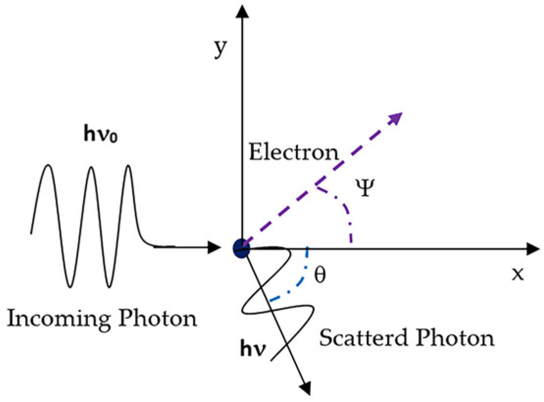
Compton scattering can be discussed considering two aspects: kinematics and cross section. From a kinematic point of view, a photon of energy Eγ hitting an electron of an atom assumed as free (binding energy Eb << Eγ, Klein-Nishima (K-N) hypothesis [45]) transfers part of its energy to the electron which is removed from the atomic shell and put into motion with kinetic energy Te while the photon is scattered. The energy of the scattered photon depends on the scattering angle θ (Figure 2). Under the K-N hypothesis, the relation between photon deflection and its energy loss is determined from conservation of momentum and energy between the photon and the recoiling electron [46]:
E γ = E γ 1 + E γ m c 2 ( 1 c o s θ )
where E′γ is the energy of the scattered photon, mc2 the rest energy of the hit electron, and cosθ the scattering angle of the photon (Figure 2). Introducing the so-called Compton wavelength: λC = mc2/Eγ, it can be demonstrated that after the collision the Compton wavelength λ′C is [46]:
λ′C = λC + (1 − cosθ)
so that the maximum shift in wavelength is for θ =180° (back-scattered photon). As far as the Compton differential cross section (dσC/dΩ) is concerned, it is given (for the case of un-polarized photons) by the well-known K-N formulae [45]:
d σ C d Ω = r 0 2 2 E γ E γ 2 ( E γ E γ + E γ E γ s i n 2 θ
where r0 = e2/mc2, e is the electron charge and E’γ is given by Equation (2) and the other quantities are defined as in Equation (2). Integrating the differential cross section over all photon scattering angles, the total K-N cross section σC is obtained. It is important to note that both differential and total K-N cross sections are independent from the atomic number Z because the electron binding energy was neglected, thus σc results proportional to Z. As a consequence, the K-N Compton cross section for an atom with atomic number Z is given by [47,48]:
σ C Z = Z   * σ C   ( cm 2 / atom )
Equation (3), and by consequence Equation (4), is limited toward both high and low photon energies. At a few keV photon energy, Eb is no longer negligible, while at high photon energy (>few MeV) there could be probable emission of an additional photon (double Compton effect) and also radiative emission, the latter associated with emission and re-absorption of virtual photons for which other more appropriate formulae are used but not discussed here [49]. Furthermore, at low energy, the already discussed onset of Rayleigh scattering (mainly for high Z materials) and, even more, the presence of photoelectric effect are dominating the photon-matter interactions.
In the photoelectric process [41,50], the atom loses one electron as a consequence of the photon collision with one of the electrons bound in a given energy level (e.g., K, L, etc.) of the atom. The condition to be fulfilled by the incoming photon to remove the electron is that its energy (Eγ) is at least slightly greater than that of the binding energy Eb of the electron in the given level of the atom. The kinetic energy Te- of the removed electron is then given by:
Te− = Eγ − Eb
Once the electron is removed, the atom usually emits X-rays with energy depending on the level occupied by the electron. The most energetic X-rays are those emitted by the most internal shell, namely the K shell. As far as the photoelectric cross section (σpe) is concerned, it is found that it depends on the photon energy as well as on Z, resulting, by far, the most important interaction for X-ray radiation. The interaction cross section per atom, integrated over the solid angle can be written as [41]:
σ p e f Z n ( E γ ) m   ( cm 2 / atom )
where f is a constant. As far as n and m are concerned, it is found:
n ≈ 4 at Eγ ≤ keV, however n slowly increases up to 4.6 for Eγ = 3 MeV;
m ≈ 3 at Eγ ≤ keV, however m is slowly decreasing to about 1 at Eγ = 5 MeV.
Concerning the shape of the σpe cross section, it is worth mentioning that if Eγ ≤ Eb the electron cannot be ejected from the atom. Hence, a plot of the σpe versus Eγ exhibits the characteristic “absorption edge” structure [48] (see Figure 3).

Photon Attenuation

An important consequence of photon interactions with matter is the attenuation they suffer when passing through it. Using a collimated beam of photons impinging on a material (absorber) of thickness T, it is observed that the beam is attenuated by a simple exponential attenuation law. Each one of the interaction processes mentioned in Section 3.1 contributes to remove photons away from the initial beam direction. Each removal process can be characterized by a probability of occurrence μj per unit path length (Lpl) in the absorber (the path length is defined as the average distance travelled by a photon between two collisions). The sum of all these probabilities is the total probability, per unit path length, the photon will be removed from the beam [48]:
μ T o t = j μ j = μ p e + μ c + μ e e + μ R
In Equation (8), the various μj are identified with the same notation used for indicating the cross sections for photoelectric, Compton, pair production and Rayleigh (and Raman) effects. The number I(x) of transmitted (uncollided) photons at distance x is then given in terms of the initial number I0 of photons, as:
I(x) = I0 exp(−μTot x)
μTot is called total linear attenuation coefficient and is measured in (cm−1). The quantity λTot =1/μTot (cm) is called mean free path and represents the average distance travelled by a photon between two collisions. Equation (9) can be re-written as:
I(x) = I0 exp(−x/λTot)
The total (μTot) and partial (μj) linear attenuation coefficients defined above are proportional to the absorber density ρ (g/cm3) which, usually, can vary depending upon the physical status of the material. This is why the attenuation coefficients (both total or partial) are normalized to density so removing this dependence. The new quantity, the so-called μ/ρ, is measured in (cm2/g). Furthermore, μ/ρ results proportional to the cross section σ per atom defined in Section 3.1 [48]:
μ ρ cm 2 g = σ cm 2 Atom N A [ atoms g atom ] M [ g g atom ] = σ b atom N A M 10 24
where N A is Avogadro number (6.02252 × 10²³ atoms/g*atom) and M is the atomic weight of the absorber material; the latter are tabulated (see e.g., [51]). Equation (11) applies to (μ/ρ)j for each one of the j-th interaction processes discussed in Section 3.1 as well as the total (μ/ρ)Tot = Σj (μ/ρ)j.
To conclude, it is worth mentioning that, due to the low atomic number (Z = 6), diamond is a highly transparent material for gamma and X-rays. However, it is a favorable detector material for X-ray not only in synchrotrons and FEL facilities, but very thin diamond films are applied in medical dosimetry to measure intense gamma/X fields (flash detectors, [52]). Figure 3 reports (μ/ρ)Tot versus photon energy for diamond compared to Platinum, Chromium and Aluminum (three metals often used for realizing the electrical contacts). The typical absorption edge structures are well evidenced for the three metals.

3.2. Optical Photons Attenuation

Equation (9) is a general attenuation law valid over the whole range of the EM spectrum and it applies well to photons of energy greater than a few hundred eV for which the photoelectric effect is still governing the radiation absorption. Therefore, when the energy of photons goes down to the range of a few tens of eV or less (Table 2), the process which underlies the absorption of photons involves also intrinsic optical physical properties of solids, including junctions, whether present. Let us recall that in diamond (and semiconductors), UV absorption provides enough energy to promote electronic transitions from valence to conduction band (if Eγ ≥ Eg).
When considering low energy photons (assuming photons of intensity I0 incident on a material of thickness d), the intensity of the transmitted photons at a distance x is given approximately by the Beer’s law:
I(x) = I0 × exp (−αd)
where α is an absorption constant. Equation (12) is formally the same as Equation (9) with α measured in (cm−1) playing the role of μTot. Therefore, its physical meaning is quite different since α is depending upon the optical properties of the material and it is related to the extinction coefficient k defined by:
ε = (n + ik)2
where ε is the dielectric constant and n and k are the refraction index and the extinction coefficient, respectively [3,53]. To note that k is the imaginary part of the dielectric constant and it is related to absorption while the real term (n) is related to reflection/transmission. The relation which relates α to k is [54,55]:
α = 4 π k λ
where λ is the photon wavelength. Figure 4 shows n and k for diamond versus photon energy. To note that k tends to zero both for photon energy decreasing toward zero and for photon energy increasing above 35 eV. For diamond, in the UV region, k is almost zero while both n and k are influenced by the CH4/H2 ratio used in the gas growing mixture [53] in the CVD process.
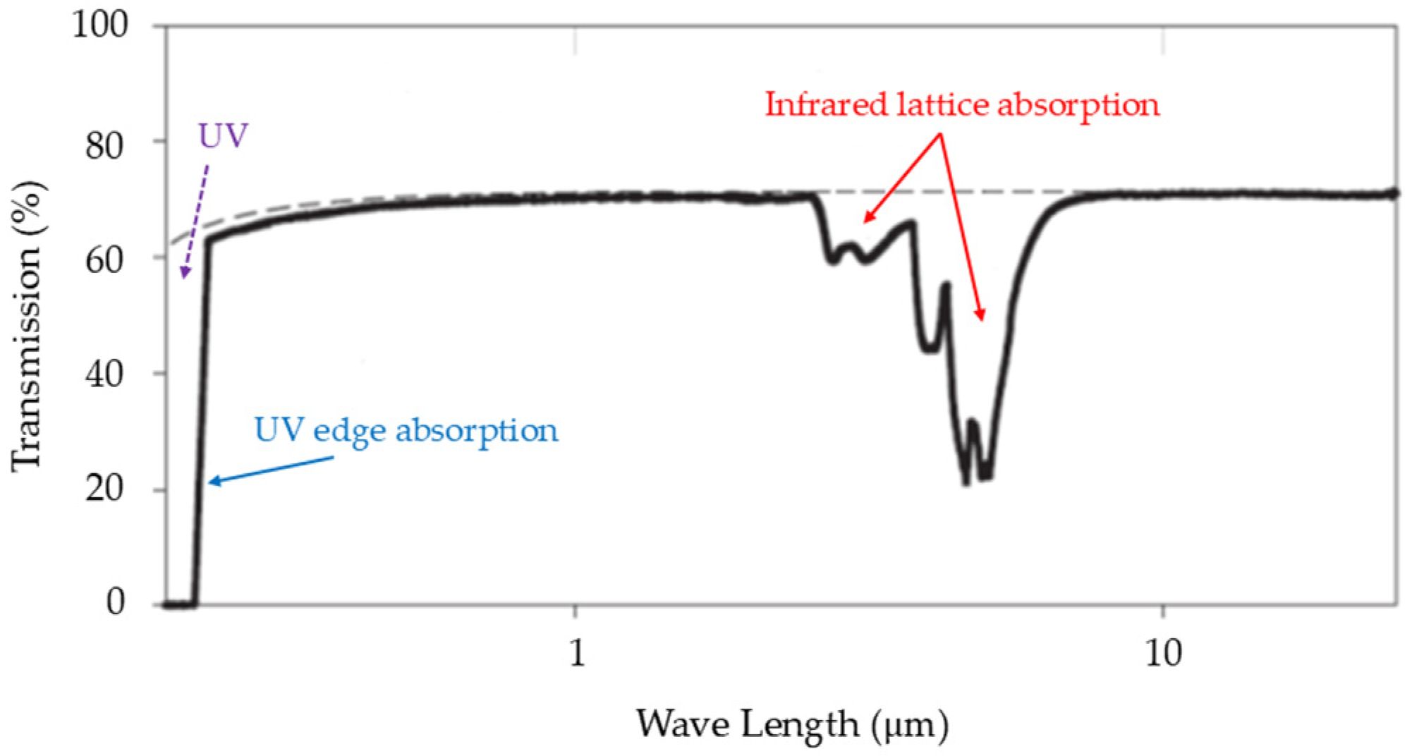
Thanks to its wide band-gap and lack of first-order infrared absorption, CVD diamond results in one of the most broadly transmitting of all solids, rendering it very suitable, e.g., for windows. The transmission spectrum for diamond is almost flat for wavelengths longer than approximately 225 nm (α < 1 cm−1 for λ > 235 nm), apart from a moderate absorption in the range 2600 ÷ 6200 nm (Figure 5). It is a characteristic of the Group IV elements (e.g., Si and Ge) that there is no absorption in the long-wavelength limit. The wavelength dependence for transmission is mainly governed by UV-edge absorption, infrared lattice absorption, and Fresnel reflection [56].

4. Photodetectors

Photodetectors are optoelectronic devices that convert the incident photon energy into electrical signal over a given range of the electromagnetic (EM) spectrum defined mainly (but not uniquely) by the material properties (e.g., band-gap). The type and material of photodetectors are selected based on the requirements and constraints of the given application: wavelength range of photons to be detected, detector sensitivity and response time. Typically, photodetectors exhibit an almost uniform response within a specific range of the EM spectrum.
UV/X-ray detectors based upon wide band-gap semiconductors such as diamond are increasingly studied because they are insensitive (blind) to the visible region of the EM spectrum avoiding the use of filters.
This section presents a short but comprehensive discussion of the basic theory of CVD diamond UV/X-ray detectors. Further considerations, restricted to advanced diamond UV/X detectors, their state-of-the-art, and applications, will be presented in Section 5.

4.1. Photodetection in Semiconductors: Sketch of Theory

As already stated in Section 3, photo-detection in semiconductors operates on the general principle of creating electron-hole (e-h) pairs when the semiconductor is illuminated by photons of energy Eγ ≥ Eg. The absorbed photons promote electrons from the valence band into excited states in the conduction band. These electrons behave like free electrons and under the influence of an intrinsic or externally applied electric field E can travel long distances across the crystal structure. Additionally, due to the electric field, the positively charged holes left in the valence band contribute to electrical conduction by moving from one atomic site to another in opposite direction to the electrons. The e-h pairs generate a photocurrent whose intensity, at a given photon wavelength, is a function of the incident photons intensity. A photocurrent can also result from thermal effects, called dark or leakage current. Typically, the dark current increases exponentially with the absolute temperature T and, in a large band-gap semiconductor, represents a negligible “background“ compared to the photon-induced current. Typical diamond photodetectors dark current values are below the fempto-ampere. The dark current is a good indicator of the detector quality.
The probability to promote an electron from the valence to the conduction band at a given absolute temperature T is given by [38]:
p T = S M T 3 / 2 exp ( E g 2 K B T )
where KB is the Boltzmann constant and SM a constant depending on the material, Eg is in eV.
Semiconductors are usually classified for presenting direct or indirect band gap, see Figure 6. Table 3 shows a not complete list of direct and indirect band-gaps semiconductors [55].
In a direct band gap semiconductor, for which the top of the valence band and the bottom of the conduction band occur at the same value of momentum k [38] (Figure 6a), photon absorption occurs if an empty state in the conduction band is available. The energy and momentum of the empty state must equal that of an electron in the valence band plus that of the incident photon [38]. Photons have little momentum compared to their energy (kγ = Eγ/c) since they travel at the speed of light. Therefore, the electron makes an almost vertical transition on the E-k diagram (Figure 6a).
In an indirect band-gap semiconductor, such as diamond, the top of the valence band and the bottom of the conduction band occur at different values of momentum k [38], meaning the conduction band is not vertically aligned with the valence band (Figure 6b). An electron must also undergo a significant change in momentum for a photon of energy Eg to produce an e-h pair. This is possible if the electron interacts not only with the photon to gain energy but also with a lattice vibration (phonon) to gain or lose momentum. Since a phonon has a relatively low velocity, close to the speed of sound in the material, it has a small energy but large momentum compared to a photon, compensating for the missing momentum. Thus, energy-momentum conservation in the e-h production can be achieved if a phonon is created or an existing phonon participates in the e-h production. To note that the minimum photon energy Ec that can be absorbed is slightly below the band-gap energy Eg in the case of phonon absorption, while it must be slightly higher than Eg in the case of phonon emission. Furthermore, since the absorption process in an indirect band-gap semiconductor involves also a phonon (three body interaction), the probability of interaction will be lower than in the case of a simple electron-photon interaction in a direct band-gap semiconductor. As a result, absorption is much stronger in a direct band-gap material [56]. The phonon and non-phonon assisted absorption processes are illustrated in Figure 6a and Figure 6b, respectively.

4.1.1. UV Absorption in Diamond

The UV absorption edge for diamond begins at 227 nm corresponding to photon energy of 5.46 eV, slightly lower than the bottom of its energy band-gap (5.48 eV). The band gap is indirect; this requires the excited electron to gain momentum in one of the <100> crystal directions. The absorption near the UV edge results in a three-body interaction, requiring either the absorption or emission of a lattice phonon. Close to the gap, the UV absorption is also influenced by the created electron-hole pairs which interact among themselves by a weakly attractive force, forming an exciton with a binding energy Ex = 0.07 eV, at room temperature. The exciton also acts to slightly reduce the energy required to span the band-gap [56] (Figure 7).
The UV absorption is also temperature dependent. It has been observed [57] that with increasing temperature the absorption edge is influenced by the thermally excited phonons and the downshift in the phonon energy due to lattice expansion (e.g., in the temperature range 126 K < T < 661 K the shift corresponds to less than 0.1 eV [57]). For temperatures above 300 K, increased absorption at wavelengths longer than 236 nm (corresponding to photon energy < 5.26 eV) is observed, attributed to the increased density of thermal phonons and the onset of absorption events involving two or more phonons. For T < 300 K, reduction in absorption relying on single-phonon absorption is observed, shifting the absorption edge progressively towards the 226 nm threshold (E = 5.482 eV) corresponding to phonon emission [57].

4.1.2. Carriers Production and Recombination

In a real semiconductor, due to the presence of imperfections (e.g., impurities), the band-gap is not completely empty, and there could be energy levels between the valence and conduction band (Figure 8). Consequently, once a free electron (or a free hole) is produced, it may be captured at an imperfection (see e.g., Figure 8d,e) for electrons and holes, respectively). The capture process is described through a capture coefficient β and the rate of capture RC of a species with density n (either e or h) by an imperfection with density Ni is given by [58]:
RC = βnNi
The capture coefficient β can be expressed as:
β = S E υ ( E ) = S ν
where S(E) is the capture cross section and ν is the velocity of free carriers and the average is over the whole electron energy range. The capture of an electron (hole) leads to recombination with a hole (electron), and before the free carrier recombines it survives for a lifetime τ given by:
τ = 1/βNi
Comparison with Equation (16) shows that the rate of capture (or recombination) is equal to n/τ. At the steady state, the rate of recombination must be equal to the rate of excitation Rexc (per unit volume per second), thus:
n = Rexcτ
Equation (19) is a fundamental relationship for all photo-electronic phenomena.
A charge carrier (e or h+), apart from recombining with a carrier of opposite type as described above, can also be thermally re-excited to the nearest energy band before recombination occurs. In this latter case, the imperfection is referred to as a trap and the capture and release processes are called trapping and de-trapping, respectively (see Figure 8f). While the trapping rate can be described by Equation (16), the de-trapping rate Rd depends upon the absolute temperature T:
Rd = nt Sesc × exp(−Ea/KBT)
where nt is the density of trapped carriers, KB is the Boltzman constant, Sesc is a material characteristic “attempt to escape frequency”, and Ea is the activation energy for de-trapping. The imperfections in the lattice act like a recombination centre if RC > Rd but as traps if RC < Rd.
The electrical current flowing under illumination, as depicted in Figure 8, involves two additional considerations: (a) the effect of the electrical contacts (see Section 5.2); (b) the nature of the transport of free carriers. The latter can be explained by the Drude model [59]. An electron moving inside a solid in the presence of an electrical field E experiences a force F given by [38]:
F = m * d υ d t = q E m * τ c v d
The first term represents the drag term of the electron charge q and it is due to the driving force of the electric field E, while the second term is a damping force resulting from the collisions of electrons within the material. m* is the effective mass of the electron in the solid, τc is the time in between two consecutive collisions (collision time) suffered by an electron, and vd is the so-called drift velocity. If vd is constant, its derivative with respect to time is zero, thus:
υ d = q τ c m * E = μ E  
μ is the mobility (cm2/Vs) (in diamond e and h present different μ values). Notably, μ depends upon m* and τc which are intrinsic physical properties of the material. Equation (22) shows that vd increases with the electrical field; therefore, contrary to what it might seem, the increase is not linear versus E. This is because μ, in turn, is a non linear function of E (see Equation (24)). Concerning diamond, for E > 1.4 ÷ 1.5 V/μm, vd tends to saturate up to reaching the saturation drift velocity (vds) [60]. The drift velocity versus the electric field can be written as [60,61]:
v d = μ 0 E 1 + μ 0 E v d s   ( cm / s )
where μ0 is the low field mobility of carriers (for E < 0.1 V/μm). Fitting the data of the measured vd versus E by using Equation (23), Pernegger [62] derived the saturation drift velocity for electrons (vdse = 9.6 × 106 cm/s) and holes (vdsh = 1.4 × 107 cm/s), respectively, at room temperature for diamond. It is worth noting that the mentioned saturation values for E are just above those typically used for operating diamond (and semiconductor) detectors (E ≤ 1 V/μm). At low electrical field value (E < 0.1 V/μm), the drift velocities of electrons and holes tend to be the same [62].
Concerning the mobility, by combining Equations (22) and (23), we obtain:
μ e , h = μ 0 ( 1 + μ 0 v d s E )   ( cm 2 / Vs )
This is the so-called effective mobility. Equation (24) is valid in the same range for E where Equation (23) applies. According to Equation (24), the charge carrier mobility is the highest at low E field strength and decreases as E increases, which was experimentally observed [62]. For diamond at room temperature, the hole mobility is the highest among semiconductors. For E < 0.1 V/μm, values of μ0e = 1714 cm2/Vs and μ0h = 2064 cm2/Vs for electrons and holes mobility, respectively, were reported [62]. Furthermore, when operating a semiconductor detector in the region of low-field mobility, μ is independent of E and only in this case Equation (22) is linear and the current flows according to Ohm’s law. At high electrical field, the scattering process becomes dominant so that the average kinetic energy of the charge carriers does not increase. This leads the drift velocity (vd) to be independent from E and thus μ 1 / E (see Equation (24)).
The current density J of electrons flowing in a material with drift velocity vd is related to the mobility μ by [38]:
J = nqvd = nqμE = σE (Coulomb/(cm2 s))
where n is the electron density (cm−3). The proportionality factor σ between the current density and electric field strength is called the electron conductivity and, using Equation (23), can be written as:
σ = n q 2 τ C m *   ( Coulomb / cm 3 )
In a semiconductor, since electrons and holes have opposite charge and thus opposite drift velocities, the total current density is therefore obtained by adding the electron and hole current density Je and Jh:
J = J e + J h = q n e μ e + n h μ h E
The linear relationship between J and E is valid only if the electric field is lower than a specific value related to semiconductor type (E ≤ 1 V/μm).

4.1.3. Charge Carriers Transport and Ramo–Shockley Theorem

The operation of a photodetector involves three steps: (I) carrier generation by the incident light; (II) carrier transport and/or multiplication by any current gain mechanism present; and (III) charge induction on electrodes producing current on an external circuit, providing the output signal. It is worth noting that to obtain the signal output, it is not necessary for the carriers to actually reach the electrodes to generate the induced current. This is due to the Ramo–Shockley’s theorem [63,64], which applies to semiconductors and thus also to diamond. Furthermore, according to Equation (27), since both e- and h+ generate the induced current at the electrodes, the total current flowing in the external circuit is the sum of the electron and hole induced currents.
In the case of a diamond detector of thickness L made with two plane parallel electrodes, by applying the Ramo–Shockley’s theorem, the instantaneous charge dQ induced at the electrodes by a charge q generated at a distance dx from one of the electrodes can be calculated as [63,64]:
d Q = i d t = q d x L
Considering the case of a minimum ionizing particle (MIP) passing through a diamond detector, it produces, in diamond, 36 pairs of e and h+ per micron. Calling this quantity q0, the charge produced by a MIP in a distance L is thus Q0 = q0L; this is the maximum total charge produced in a (perfect) diamond detector of thickness L by a MIP. However, it could happen that the charges are trapped in the defects present in the detector after moving a distance Lc < L. Lc is called the charge-collection distance (ccd). In this case, the effective collected charge QC is:
Q c = Q 0 L c L
from which we get:
L c = L Q c Q 0   [ μ m ]
Thus, by measuring QC, we can determine the ccd of the detector. The ccd is directly correlated to the diamond film quality (amount of impurities and defects and thus of trapping levels). For a more detailed analysis of the charge induced in diamond detectors, see references [25,65].
A different definition for Lc can be provided in terms of the drift velocity vd and drift time τd of the charge carriers:
L c = v d τ d = μ E E τ d = ( μ e τ e + μ h τ h ) E   [ μ m ]
where μτ is the mobility-lifetime product of the e- or h+ carriers, respectively, and E is the electric field. Equations (30) and (31) are equivalent.

4.2. Performance Characteristics of a Photodetector

A high-performance photodetector should satisfy five requirements (5R rule): high sensitivity, high signal-to-noise ratio, high spectral selectivity, high speed, and high stability [66,67,68]. This 5R rule defines the performance characteristics of the detector. In some cases (e.g., flame detection for a hot engine, plasma physics), thermally stable detectors are also required.
The response of the photodetector should be high at the wavelength range to be detected and negligible outside it. The additional noise (and/or dark current) introduced by the detector should be small compared to the generated photoconductive current (high signal-to-noise ratio). The photodetector must have fast response time so that the time-dependent variations of the input optical signal can be detected and reproduced real-time. The main performance characteristics of diamond photodetectors are briefly summarized below.
Quantum efficiency: it is defined as the ratio of countable events (photoelectrons or e-h pairs) produced by the incident photons to the number of incident photons. The quantum efficiency is generally expressed in a percentage and is another way of measuring the effectiveness of the incident energy to be converted into electrical current. It can be either internal or external.
The internal quantum efficiency (ηint) is the number of e-h pairs created per absorbed photon.
The external quantum efficiency (ηext) is the number of photons detected or counted by the device; it is given by [69]:
η e x t = I p h q h υ P i n c
where Iph is the photocurrent; Pinc is the incident optical power; hν = Eγ is the photon: energy and q is the electron charge. The ηext depends on a number of factors such as the absorption coefficient α of the material and thus on the photons’ wavelength λ and the thickness d of the absorbing region (cfr. Section 3.2), thus:
η e x t ( 1 e α d )
It is worth mentioning that ηint >> ηext. For diamond, in the UV energy range, ηext results greater than unity at about 35 eV [70].
Responsivity (R): it is defined as the ratio between the number of incident photons and the incident optical power [69]:
R = I p h P i n c = η q h υ   ( A / W )
It gives a measure of photodetector sensitivity to incident optical energy, thus measuring the effectiveness of the detector in converting EM radiation into electrical current. Responsivity depends upon wavelength, bias voltage and temperature. Since reflection and absorption properties of detector materials change with wavelength, responsivity is wavelength dependent and it depends upon the type of electrical contact and the detector structure.
For diamond, typical responsivity curves versus the incident photon wavelength show a flat response with mean value of about 0.1 A/W up to 100 nm wavelength, after which there is a decrease of about one order of magnitude, suggesting a dead layer located at the diamond surface, likely related to the recombination of photo-generated carriers close to the interface between diamond and contacts. For wavelengths greater than 100 nm the diamond responsivity returns to plateau value, drastically dropping at 225 nm due to the band-gap amplitude, rendering diamond insensitive to visible photons in the 225–400 nm range (the so-called visible blindness of diamond) [71,72,73].
For UV detectors, the UV/visible rejection ratio is defined as the ratio between the peak responsivity and the responsivity at 400 nm (the latter is representing the limit between visible and UV region, see Table 2). The higher the rejection ratio, the better the UV detector selects the UV photons.
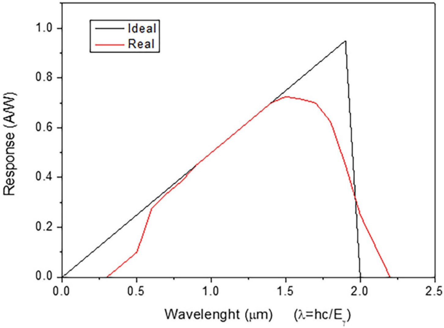
Spectral Response: it is given by the absolute responsivity versus wavelength plot. The cut-off at long wavelengths of the spectral response is determined by the absorption coefficient or the bandgap of the semiconductor. The cut-off is observed also at short wavelengths because now the value of the absorption coefficient α is very large for most semiconductors (cfr. Equation (14)), and all the incident optical energy is absorbed already near the surface [73]. The spectral response curves for an ideal and actual photodetector are shown for comparison in Figure 9.
Last, but not least, photodetectors must have linearity of the photocurrent response versus the intensity of the incident photons, in a given wavelength range of the incident radiation. If the responsivity changes with the incident radiation wavelength, then the linearity of the detector changes too. A further point to mention is that since noise will determine the lowest level of detectable incident radiation, its presence can determine a variation in the slope of the linearity curve.

4.2.1. Response Time

The response time of a photodetector is a fundamental parameter and depends mainly on the physical properties of the used semiconductor material. Regardless of the material it is made of, a photodetector does not respond to the incident radiation instantaneously; it takes a finite time (called rise or response time) for the induced current to reach a steady-state value. Considering a pulsed light source, the detector rising time is considered as either the rise (or fall) time required for the output signal to change from 10% to 90% of its final value (or vice versa).
The response time is determined by the transit time of photo-generated carriers within the detector material and the intrinsic capacitance and resistance associated with the device. The transit time can be defined as the time required for charge carriers to move (drift) toward the electrodes under the applied electric field E. The response time of a photodetector also changes with impedance of the detector load and the impedance of the display device and may be limited also by capacitive effects, trapping/de-trapping effects, and the saturation speed of carriers in the semiconductor (which, in turn, depends on the external electrical field (cfr. Section 4.1.2)). In the past, especially using p-CVD diamond, the slow rise time was representing a limiting factor; it was overcome by using SCD diamond.
Summarizing, in a photodetector, three components participate in the total rise time:
  • the charge collection time (τCC), which is the time required for the electric field to sweep out charge carriers generated inside the semiconductor sensitive region;
  • the diffusion time (τD), which is the time needed for charge carriers to diffuse inside the semiconductor volume;
  • the rise time associated with the RC time constant (τRC), which is the time required to charge or discharge the photodiode’s junction capacitance through the external load resistance.
The total response time is equal to the square root of the sum of the squares of the three components mentioned above, and it is governed by the largest of them [69].
It should be noted that, despite the response time of diamond is intrinsically “very fast” (hundreds of picoseconds), in most UV/Xray diamond detectors the response time is limited by the electronic readout chain, typically to values lower than 1 ms. The response time of a diamond detector depends also on its geometrical configuration. Indeed, as it will be discussed in Section 5.1, two main configurations are usually used for electrical contact deposition on diamond photodetector, which are the planar and transverse configurations. Considering just the diamond photodetector, typical values of the intrinsic response time are of the order of hundreds of picoseconds for the planar configuration and tens of nanoseconds for the transverse configuration.

5. Diamond UV and X-Ray Photodetectors

As discussed above, diamond is blind to visible radiation, making it well suited to UV and soft-X ray detection. Furthermore, SCD diamond meets the 5R requirements, offering the highest figure-of-merit for high-performance deep UV detectors [26,71]. In addition, diamond UV and X-ray photodetectors have small size, may not require cooling even when operated at high temperature, and have high radiation hardness, resulting ideal for application in harsh environments.
Historically, several attempts have been made to realize photodetectors from natural and synthetic p-CVD or single crystal CVD diamond. One of the earliest attempts was a UV photoresistor [74,75] featuring a planar structure and consisting of a photoconductive diamond film with metal electrodes placed on the top and bottom surfaces. An external voltage was needed to operate the detector. Therefore, the current signal was affected by secondary electrons emission, which is known to impact detection properties in the UV and EUV spectral regions.
An alternative design reported in the literature [76,77] is based upon a CVD polycrystalline layer sandwiched between one electrical contact deposited on the diamond growth surface and another backside contact deposited on the silicon substrate. However, the performance is limited by the polycrystalline structure [28,78], which affects the charge carriers transport and thus the detection characteristics. On the other hand, detectors based upon HPHT single crystal diamonds have their performance strongly worsened by the large number of defects and impurities [79] present in this type of diamond, while detector grade single crystal natural diamonds are extremely rare and expensive.
To overcome these limitations, in the last decades, great effort has been devoted to producing device-grade single crystal diamond (SCD) layers by homoepitaxial MWPECVD growth on low-cost single crystal diamond substrates, usually of the HPHT type [72,80].
In the following sections, we will detail the fabrication process and the underlying physics of CVD single crystal diamond photodetectors. Since the fabrication process is basically the same, we will not distinguish between UV and X-ray detectors unless this is necessary (see, e.g., Section 6).

5.1. SCD Diamond Photodetectors

A diamond photodetector is made of an intrinsic SCD diamond layer with contacts deposited in either planar or transverse configurations (Figure 10).
In the planar configuration, two sets of interdigitated conductive fingers are placed on one of the surfaces of the intrinsic SCD layer (Figure 10a). In the transverse configuration, the contacts are placed on both surfaces of the intrinsic SCD layer (Figure 10b). The different configurations result in different detection performances and the choice between the two is made to better suit the application requirements. The planar configuration with interdigitated contacts (PIC photodetector) is better suited for UV detection, while the transverse configuration or metal-intrinsic-metal, MIM in the following, can be used either for UV or X-rays detection depending upon the thickness of the intrinsic diamond layer. The latter is usually 0.5–2 μm thick for UV and up to several tens of microns for X-rays, respectively.
Metal contacts are deposited by evaporation or sputtering technique making use of proper masks realized using photolithographic technique. Different metals (e.g., Cr, Ti, Ni, Ag, Au, Pt, W) can be used to deposit the contacts (metallization procedure [81]); the deposited layer has typical thickness in the range 5–200 nm. Often, two (or even three) layers of different metals are deposited to form a contact (e.g., Ti/Pt, Cr/Au, etc.) with the metal on top usually used to avoid oxidation of the lower one (e.g., Ti/Ag), which is forming the actual electrical contact. Depending upon the fabrication procedure, the metal-diamond junction forms either Schottky or ohmic contacts resulting in different behavior and performances for the photodetector. To this end, production of high-quality electric contacts is of paramount importance for diamond photodetectors’ applications, as will be discussed in Section 5.2.
The transverse configuration (MIM) provides a homogeneous electrical field across the intrinsic diamond region, but the metallic contact deposited on the top surface acts as a filter for the radiation impinging on it. For this reason, it is important to properly choose the metal and optimize its thickness (see Section 6). This is much more relevant for UV radiation, and the effect of the metal contact can be mitigated using the planar configuration but, in this case, the electrical field inside the diamond is not homogeneous. For planar configuration, the thickness of the diamond layer is not relevant since the carriers are transported on the diamond surface in the very first few atomic layers. Usually, a very thin intrinsic diamond layer is used (0.5–2 μm).
The application of an electric field to the diamond volume will cause a current to flow, and, for a beam of photons that is fully absorbed in the diamond, the photoconductive signal Iph, defined as the difference between the current measured under photon irradiation and the dark current (i.e., current measured without radiation exposure), is given by:
I p h = q ϕ p h η G   ( A )
where q is the elementary charge, Φph is the photons-flux intensity on the detector surface (photons/s), η is the internal quantum efficiency (i.e., the ratio between the number of e-h pairs and the number of photons absorbed by the semiconductor, 0 < η < 1, see Section 4.2), and G is the photoconductive gain. G is the number of carriers detected per e-h pair generated per photon and it is defined as the ratio between the ccd (Lc) and the distance between the two electrodes, d:
G = L c d
G can be >1, which can be interpreted in terms of electrons flowing round the circuit several times before they recombine with photo-generated holes. Using Equation (31) per Lc and Equation (36), Equation (35) can be rewritten as:
I p h = q ϕ p h η ( μ e τ e + μ h τ h ) E d   ( A )

5.2. Ohmic and Schottky Electrical Contacts

Schottky contacts are formed when a metal layer is deposited on top of a diamond surface. At the metal-diamond interface, a rectifying junction is formed with physical dimensions of a few atomic layers. The junction characterizes for a typical electrical potential Vin, also called built-in potential or Schottky barrier. Vin is due to the difference between the work functions of metal ΦM and diamond, ΦD. If ΦM < ΦD, holes diffuse from diamond to metal and, as a consequence, the metal side becomes slightly positively charged, and the diamond side slightly negatively charged, forming a junction for which Vin = ΦM − ΦD. The magnitude of the Schottky barrier depends on the used metal, ΦM typically ranges from 0.5 eV to 1.2 eV [82], while for diamond ΦD ranges from 4.8 eV to 5.8 eV, depending on type, termination of surface, etc. (see e.g., Table 2 in [9]). Detailed analysis of the Schottky barrier properties is in [83,84,85].
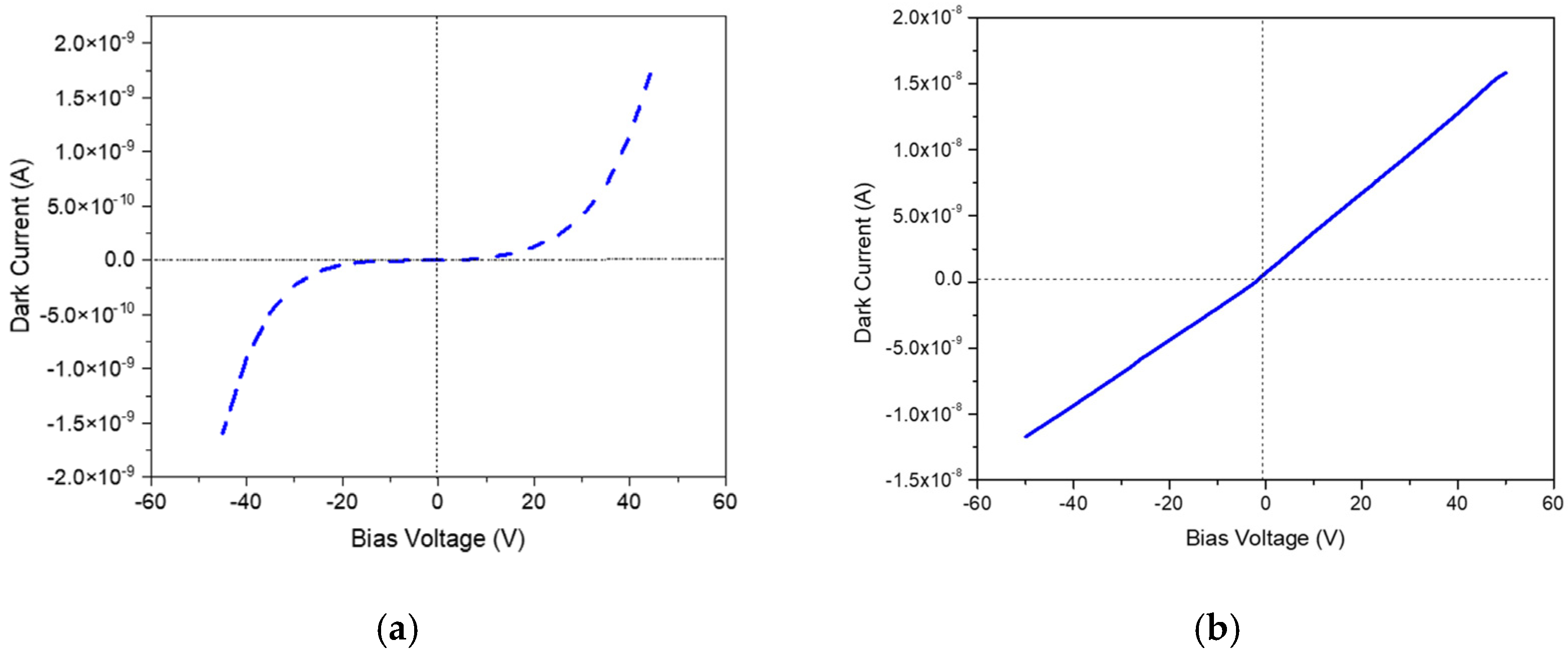
The study of barriers is usually performed by analyzing the I-V and C-V characteristics of the detector. For a Schottky contact, the I-V curve results in that of a rectifying diode, which allows the current to flow only in one direction. Therefore, for a MIM configuration such as that of Figure 10b, a typical double-diode curve is obtained (Figure 11a) because of the two Schottky contacts formed at the two diamond/metal interfaces.
Ohmic contacts exhibit a linear current–voltage characteristic (Figure 11b). The general requirements for ohmic contacts can be summarized as follows [81]: low contact resistivity, good adhesion, high thermal stability, high corrosion resistance, bondable top-layer, about zero voltage drop. After the metal deposition on diamond, to obtain an ohmic contact, the diamond sample must be annealed in vacuum or inert atmosphere. Annealing time and temperature (T) depend on the type of metal. Usually, 300 °C < T < 600 °C, and the annealing time is in the 10–60 min range. During the annealing, metals react with diamond forming carbides [86,87] and resulting in a final ohmic contact [88], which characterize the formation, at the interface diamond/metal, of a thin film (1–3 nm) called diamond-like carbon (DLC) [87]. It is worth noting that some metals (e.g., Ag, Cu) keep the rectifying properties up to temperatures of about 800–900 °C, forming high temperature diodes which are studied for applications other than radiation detection [89,90].
There is another method to produce ohmic contacts without using annealed metals but just a thin layer of CVD-SCD properly heavily doped with boron. To discuss this, we must remember that most contacts to common semiconductors (included diamond) are depletion contacts whose resistivity varies exponentially with the Schottky barrier height [38]. The ohmic behavior of the depletion contact can be achieved either when the barrier height is negligible (ΦM ≈ ΦD) so that the charge carriers can easily overcome the barrier (thermionic emission, [38,91]), or when the charge carriers are able to overcome the depletion region by quantum-mechanical tunneling [38]. The depletion layer width (WL) of a metal/semiconductor contact is proportional to the square root of the reciprocal semiconductor doping concentration NA (WL~NA−1/2) [82]. Consequently, WL decreases by increasing the doping concentration while the tunneling probability increases. This technique was first proposed in 1988 by K.L. Moazed and co-workers [92] and soon after developed by other authors [93,94]. The realization of the detector is completed by CVD deposition of an intrinsic layer of SCD diamond (that will act as the active volume of the detector) on top of the boron-doped one. Eventually, a metallic contact is deposited on the top face of the intrinsic layer forming a Schottky contact. In the original procedure discussed in [92], the Schottky contact was replaced by an ohmic contact by annealing of the metal contact at high temperature. It is worth noting that the metal contact can also be of the interdigitated type (see Section 5.3.2).
These detectors are called multilayered p-type/nominally intrinsic diamond/metal layered structures, in short PIM or layered detectors. They characterize for having an internal built-in potential due to the presence of the Schottky contact and one ohmic contact due to the borated layer.

5.3. SCD Layered Photodetectors

Photodetectors based on the layered or PIM structure have been produced for more than two decades at the laboratory of Industrial Engineering of Tor Vergata University of Rome (TVU) in both transverse and planar configurations. These detectors are particularly well suited for UV and X-ray detection because of the built-in potential which renders them easy to install and operate under a wide range of conditions, especially in harsh environments. In the following, we will discuss these detectors with some examples of past and future applications.

5.3.1. PIM Schottky Photodetector in Transverse Configuration

PIM diamond photodetectors in transverse configuration are produced at TVU by a two-step deposition process:
  • a conductive boron-doped diamond homo-epitaxial layer, used as a backing contact, is deposited by MWPECVD technique on a commercial low-cost synthetic HPHT <100> type Ib SCD substrate (typically of 4 × 4 mm2 in size and approximately 300–400 μm thick), Figure 12a,b. Boron doping is achievedby adding dyborane-hydrogen gas mixture (100 ppm B2H6 in hydrogen) to the CH4/H2 source gases mixture routinely used for growing the intrinsic diamond (the purity of CH4 and H2 gases are 99.9995% and 99.9999%, respectively). P-type conductive diamond with an activation energy of 0.37 eV, is obtained. The boron concentration in the p-type diamond is estimated by fitting the resistivity-temperature curve obtaining values > 1020 cm−3. Depending on the application, the boron concentration can be varied as well as the thickness of the p-doped layer (0.5–2 nm).
  • In a second step, a nominally intrinsic diamond layer, which will act as the detecting region, is homo-epitaxially grown on top of the p-doped layer (Figure 12c). This process is performed in a separate growing apparatus to avoid boron contamination of the intrinsic SCD layer. The thickness of the intrinsic SCD layer can be varied from 0.5 μm up to a few hundred of microns. For UV photodiodes, owing to the small penetration depth of the UV radiation, the detecting region has a thickness of approximately 0.5–2 μm [95]. In the case of soft X-ray detection, a higher thickness of the intrinsic SCD, usually > 15 μm, can be chosen. After the intrinsic diamond growth, the PIM photodetector is oxidized by isothermal annealing at 500 °C for 1h in air to remove the H2 surface conductive layer formed during the growing phase. Eventually, a metal electrode, about 2–3 mm in diameter or side length is deposited by thermal evaporation on the top intrinsic diamond surface while an annealed silver paint is used to provide an almost ohmic contact to the boron–doped SCD layer (Figure 12d). Figure 13 shows two SEM pictures of a PIM photodetector.
Concerning the active (intrinsic) SCD layer, its actual thickness depends on the applied external bias voltage. At zero Volt external bias, the electric field is due to the Schottky junction only. This field is sufficient to form a thin depletion layer (1–2 μm) and to drive a current when photons absorbed in the depletion layer create e–h pairs. This is the case of UV photodetectors which are usually operated without the external bias. For intrinsic diamond layers thicker than a few microns (e.g., X-ray detectors), a bias voltage of the order of 0.7–2 V/μm is applied to enlarge the depletion region and ensure uniform electrical field and detection across the entire intrinsic diamond volume.
In the PIM photodetector, the Schottky junction acts as a drift-layer and the p-type layer as holes injector. This configuration determines the unipolarity of the device under direct polarization, thus PIM photodiode operates in the reverse biased mode with a negative voltage applied to the boron-doped contact and the metal top contact (Schottky contact) grounded (Figure 14a). A typical I-V characteristics for a PIM photodiode, measured in vacuum, is shown in Figure 14b. This is the one of a rectifying diode with a very high rectification ratio (e.g., about 108 at ± 3 V external bias). To note the so-called turn-on voltage (TOV) that in Figure 14b is about −1 V (comparable to the Schottky potential). For the external voltage |V| < |TOV|, the forward current is due to generation-recombination effects and leakage superficial current and it is similar to the reverse current. Increasing the forward bias (VF), in the range between approximately −1 V and −1.6 V, the current rises exponentially with VF and the forward current is well represented by the thermionic emission (TE) [72,91,95,96,97]. This is evidenced in Figure 14b by the red straight line (named TE) which is the fit to the experimental data for the TE current (JF). The fit was calculated using the following equation, reported in [96]:
J F = J s exp e V F n K B T 1
with:
Js = A T 2 e x p ( e Φ B K B T )
and A* = 0.7 A
where: JS is the saturation current density, A is the Richardson’s constant (A = 120.173 Acm−2K−2, [98]), n is the ideality factor, T the absolute temperature, KB the Boltzmann constant, ΦB is the Schottky barrier height, e is the electron charge, VF is the applied forward voltage. From the fit, it is possible to obtain JS and thus, from Equation (39), to extract ΦB for the metal used for the Schottky contact. In the case of the measurements discussed here, for the Al contact of the used PIM detector, ΦB = 1.8 eV. A detailed analysis of the physical properties and performances of PIN photodiodes is in [95,97].
It is worth noting that a dead layer of about 5 nm thick was experimentally found just below the metal–diamond interface. Its presence is only relevant for low energy photons (UV) and it must be taken into account to reproduce the experimental responsivity curves of the PIM photodetector at energies below 30 eV [99] (see Section 6).

5.3.2. PIM in Planar Configuration and Interdigitated Finger Electrodes

PIM structure can also be produced with interdigitated contacts directly on the growth surface of the SCD intrinsic layer. A key difference compared to the planar diamond photodiode described in Section 5.1 (Figure 10a) is that now one set of fingers is made of metal (aluminum) and the second set is made of p-type diamond. This detector is called interdigitated finger electrodes or IDT-PIM photodetector.
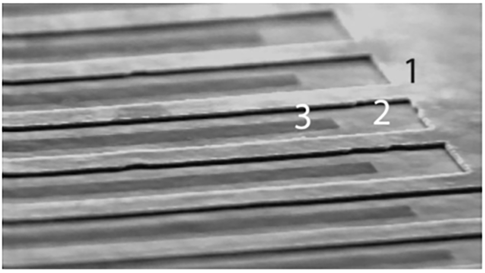
The fabrication process involves a two-step standard photolithographic technique (Figure 15). The reported production procedure is the one in use at Tor Vergata University of Rome (TVU). Once the intrinsic diamond layer is homoepitaxially grown on the HTHP substrate by MWPECVD, p-type SCD interdigitated fingers are selectively grown on the top of the intrinsic SCD layer by using a patterned Chromium plasma-resistant coplanar mask (Figure 15a–d). After removing the Cr mask by wet etching, an interdigitated Al electrode is fabricated by using a second mask, aligned to the previously obtained pattern (Figure 15e,f). The Al fingers are patterned by standard lift-off photo-lithographic technique and deposited by thermal evaporation onto the CVD-grown intrinsic diamond surface. The width of the pattern and the gap between two fingers are both of 20 μm (customizable). The final configuration is shown in Figure 15g. A SEM picture of a IDT-PIM device is in Figure 16.
The I-V characteristics of the IDT-PIM photodiode as well as the rectification ratio (about 108) are similar to that of a PIM photodiode as it could be seen from Figure 14b (red curve). The current measured under forward bias follows the one expected from thermo-ionic emission. In this case, the fit to the experimental data was calculated using Equation (38) and the ΦB value for its Al contact derived via Equation (39), resulting equal to 1.65 eV.
The measured photocurrent of a PIM or IDT-PIM photodetector is the sum of both photoemission current and photoconductive current [100]. The former contribution contains secondary electron emission (see Section 5.4.1) arising from metal and, for IDT-PIM, also from p-type SCD fingers (Figure 14a).
The IDT-PIM detector discussed above is just an example of what can be realized thanks to the photolithographic technique. Other configurations for the electrical contacts can be realized, allowing, for example, to obtain multi-pixel detectors that can be used as position-sensitive (or imaging) sensors (see Section 6 and Section 7).
A very important feature of both PIN and IDT-PIN photodetectors is the signal-to-noise (S/N) ratio. Figure 17 shows the measured S/N ratio as function of the external bias voltage for both PIN and IDT-PIN photodetectors [95]. In both cases, the measurements were performed irradiating first the detectors with UV from a He-Ne lamp and then selecting a specific UV energy using a monochromator. As clearly shown in Figure 17, the S/N ratio gets the maximum when the external bias voltage is zero, which is when both detectors are operating solely on the built-in potential of the Sckottky contact. This is one of the main reasons to operate these detectors without external bias, at least for UV.
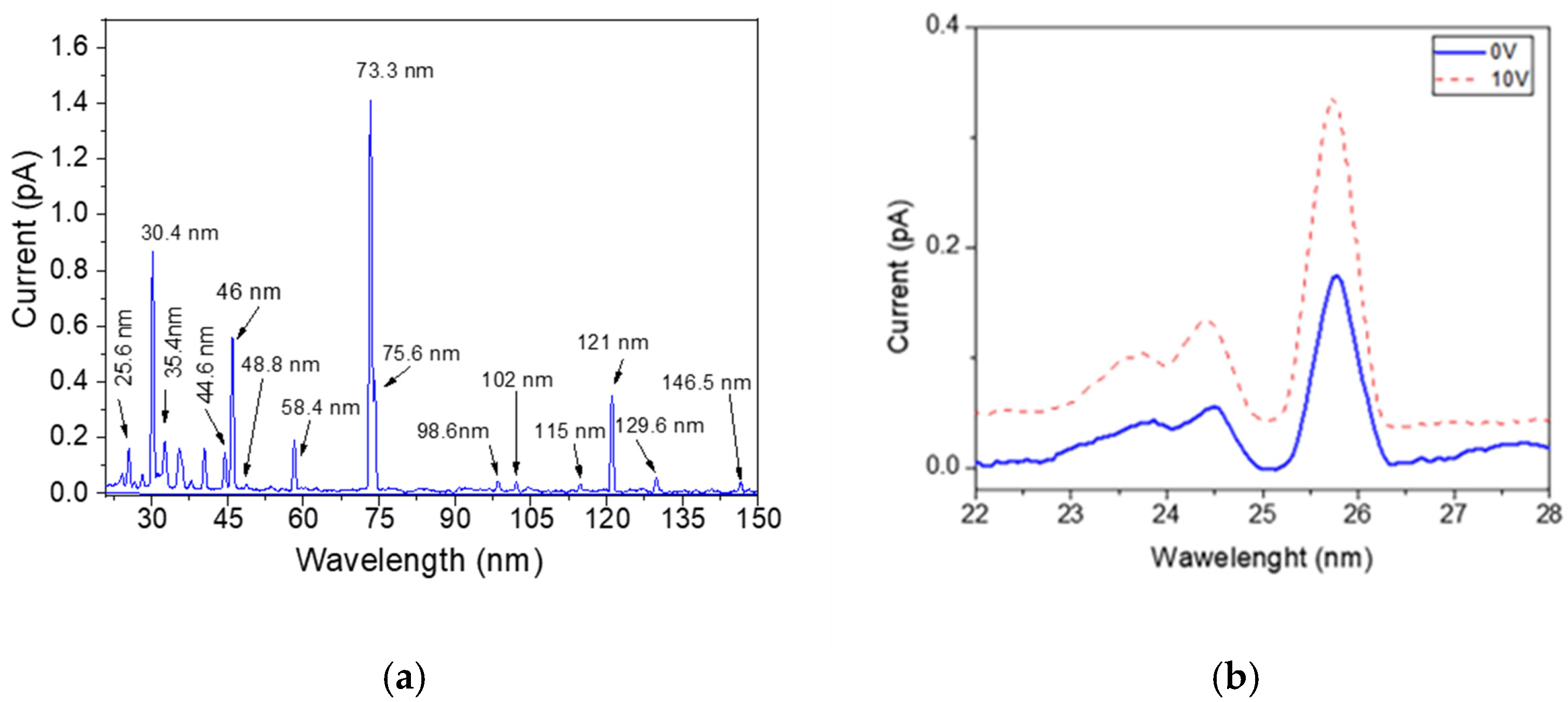
Another important feature of photodetectors is their spectrometric performances. As an example, Figure 18a shows some UV lines measured by a PIC photodetector when exposed to UV radiation produced by a He-Ne lamp with wavelengths in the range 20–120 nm. The lines were selected by means of a monochromator [95]. The reported data were measured operating the PIC detector in the unbiased mode. Figure 18b is a magnification of Figure 18a in the extreme UV (EUV) wavelengths (22–28 nm) and shows the excellent spectrometric performances in terms of energy resolution of the detector at the EUV range. Figure 18b shows also the effect of the external voltage on the energy resolution (red dotted line). The measure at 10 V was performed by means of the same He-Ne lamp and monochromator used for the data measured at zero Volts [95].
The spectral response of a IDT-PIN photodetector operated at zero bias and exposed to a He lamp is shown in Figure 19. The He+ 25.6 nm and 30.4 nm as well as the He++ 58.4 nm emission lines are clearlyresolved, showing also in this case very good detection capability even in the EUV spectral region. However, compared to the PIM detector, a lower energy resolution is observed as indicated by the lack of the less intense lines, compared to Figure 18b. Therefore, a very high S/N ratio is observed.

5.4. Characterization of Layered Photodetectors

High quality Schottky contacts play a significant role on the overall detection performance of SCD photodetectors. The presence of the metal contact affects the responsivity of the detector especially for EUV photons. Therefore, the metal-type and its thickness need to be optimized for each specific application.
In the case of X-ray SCD detectors, the use of proper filters of variable material and thickness, usually located in front or on top of the detector, is a straightforward method to cut and tailor the responsivity curve to the need of each specific application.
The discussion above explains why photodetectors need to be characterized before each specific use in terms of responsivity versus photon energy but also in terms of temporal response.

5.4.1. Responsivity of Layered Detectors

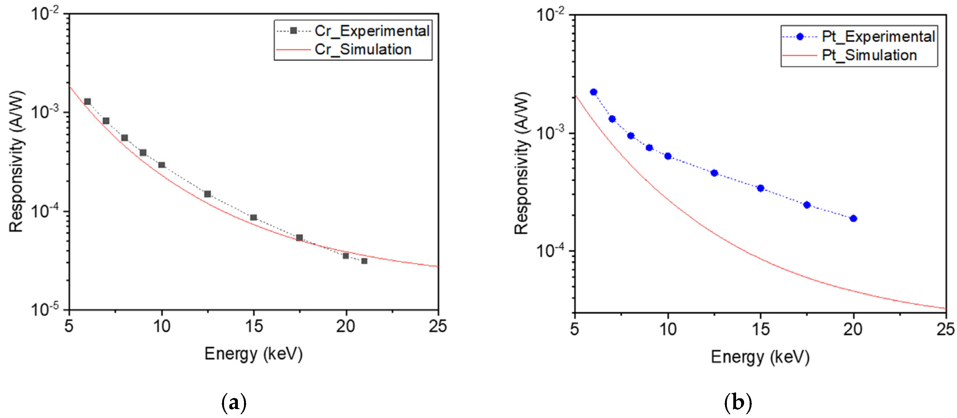
Concerning soft X-ray detectors, at photon energies greater than 1 keV the responsivity can be either calculated or measured e.g., at syncrotrons [99,100]. As an example, Figure 20 shows the responsivity (A/W) of a pair of soft X-ray SCD detectors having the same layered PIM structure with 30 μm thick intrinsic layer, but different metal contacts (Cr and Pt). To note the large difference in the responsivities between the detectors. This reflects the difference in the interaction between X-rays and different metals. In particular, the responsivity using Pt contact is higher than that using Cr contact. This is due to Pt higher atomic number than that of Cr, which leads to increased production of photoelectrons and knock-on secondary electrons that substantially contribute to the energy deposition in the diamond layer.
The responsivities shown in Figure 20 were measured at Diamond Light Source (DLS) in the UK, line B16 [100]. The solid (red) lines curves are the results of fits to experimental data calculated by the attenuation law discussed in Section 3. The dashed curves correspond, in both cases, to 3-D Monte Carlo (MC) simulations performed using the MCNP5 code [101] with a very detailed model of the two detectors, which includes the dead layer. The MC simulation shows a good agreement with measurements owing to the more accurate representation of the physics processes compared to exponential law.
In the case of UV photons, for determining the responsivity, we must rely on calculation based upon the literature data [98,102,103] and, in some cases, also on measurements using lamps emitting in the UV region [104]. As an example, Figure 21a shows responsivity curves for PIM detectors of different thickness, with or without filters of different materials (Be or Mylar), calculated from tabulated atomic scattering factors [102] for energies above 30 eV, and from refractive index data [103,105] below this value. The calculation takes into account a Pt metal contact 5 nm thick, and includes also a 5 nm thick dead layer (made of intrinsic diamond) below the metal contact [99]. Filters serve the purpose of cutting off all the low energy radiation to highlight the soft X-ray signal, but the detector response remains highly non-linear in this region. On the other hand, in the absence of filters, the detector responsivity is modulated mostly by the metal contact transmission properties up to about 1 keV, but it can be considered relatively constant down to about 60 eV.
Figure 21b illustrates the effect of the dead layer on the responsivity of a UV photodetector with an Al contact, 10 nm thick. The black points in Figure 21b are experimental data obtained in the 10–60 eV UV photon energy range exposing the UV detector to light emitted from a He-Ne DC gas discharge and using a toroidal grating vacuum monochromator (Jobin Yvon model LHT-30) with a 5 A° wavelength resolution [104]. The experimental data were compared to the theoretical curve obtained by calculating the fraction of energy deposited in the diamond layer and by taking into account absorption losses in the Schottky metal electrode.
R ( A / W ) = ( 1 e α d i a m D d i a m ) e α M e t a l d M e t a l E e h ( e V )
where Eeh is the mean electron-hole pair creation energy (13.2 eV for diamond), αdiam(λ) is the absorption coefficient of diamond (depending on the wavelength, λ), Ddiam is the active SCD thickness and dMetal is the thickness of the metallic contact. The transmission values in Equation (40) are calculated from the material thickness and the known optical constants [98,102]. The continuous blue curve plotted in Figure 21b is the result of the fit to the experimental data calculated according to Equation (40). The thickness of the tested metallic contacts and the effective thickness of intrinsic diamond (1.84 μm) estimated by the C-V curves [106] were taken into account. The fit does not reproduce the experimental data, indicating that other contributions to the responsivity must be considered. Since the UV-induced charges are generated at the metal/diamond interface, such contribution could be related to the diamond surface properties. In the investigated photon energy range, the penetration depth of photons in diamond shows a deep minimum at about 16 eV [98,102] whose trend is qualitatively similar to the responsivity curves observed in Figure 21b. This suggests the existence of a dead layer (already suggested in [107]) located at the diamond surface probably related to the recombination of photo-generated carriers close to the metal-diamond interface [107]. In the dead layer the photogenerated carriers could be trapped efficiently by the defects of the diamond surface scarcely contributing to the photocurrent. Under this assumption, in the first approximation, Equation (40) must be multiplied by the additional term exp(−αdiamδdead), where αdiam(λ) is the diamond absorption coefficient (depending on wavelength) and δdead is the thickness of the dead diamond layer. In this case a figure of δdead = 7 nm was assumed. The red dotted line in Figure 21b is the results of the calculation corrected for the dead layer [100].
One of the most relevant processes affecting the spectral responsivity in the EUV range, especially for interdigitated devices, is secondary electrons emitted from the device when photons impinge on the metallic contact and on the diamond surface [104]. These secondary electrons produce an additional current known as a photoemission current. This current depends on the experimental conditions (e.g., external electric field, pressure, etc.) and sums up to the photocurrent due to e-h pairs modifying the detector response [104]. Concerning photodetectors in the transverse configuration they can be shielded in such a way to avoid secondary electron current contribution and therefore provide a more correct and reliable response. An effective method is to ground the metal electrode and to measure the photocurrent between the p-type diamond layer and ground, for details see [104].

5.4.2. Time Dependent Response of Layered Detectors

As discussed in Section 4.2.1 the response time is of main importance to qualify the response of a photodiode. Typically, the response time is measured (at room temperature) by recording, using a pico-ammeter, the current produced by the photodetector under UV or X-ray pulsed irradiation, versus time [95,97,104]. As an example, the normalized time response under illumination of He-Ne DC gas discharge at zero applied voltage is reported in Figure 22 for an UV-PIN photo-detector made with a 2 μm intrinsic SCD layer. The detector response is plotted for the same detector equipped with different metal contacts (Cr, Pt, Au) of variable thickness (depending upon the metal) [100]. Only the detector metalized with Au shows a slow component during the rising phase of the current and a slow exponential decaying of the current when the UV signal is off. The photodetectors metalized with Cr and Pt, instead, show a very fast rising (about 60 ms) and decaying time which are totally ascribed to the used electrometer (Keithley 6517 A) amplifier time constant [100].
Concerning the time response to X-rays, the results summarized in Figure 23 refer to two different PIN photodetectors each made with 30 μm thick intrinsic SCD but the first with a Cr (20 nm thick) and the second with an Au (22 nm thick) metal contact, respectively. The test was performed at the beam line B1 of the Diamond Light Source (DLS) in the UK. For the rising time measurement, 10 keV photons were used and the detector was mounted on a mechanical chopper rotating at 3.9 kHz, placed in front of the beam line [100]. The data were acquired by an oscilloscope and a rising and falling time of 50 μm sec was observed regardless of the used metallic contact. This time is comparable to the full opening time of the used mechanical chopper demonstrating the intrinsic fast response of diamond [100].

6. Applications

The high-sensitivity detection of vacuum-ultraviolet (VUV) light and X-rays is of great significance for synchrotron radiation monitoring, free electron lasers (FEL), space science (e.g., astrophysics, satellites, etc.), the electronic industry and basic science. Below is a brief overview of some applications of UV and X-ray diamond detectors. Please note that this selection is not exhaustive and does not cover all topics. Readers are encouraged to refer to the extensive literature available for a more comprehensive understanding (see e.g., [106,107,108,109,110,111,112,113,114,115,116,117,118,119,120]).

6.1. Plasma Physics

Single crystal diamond photodectors are highly suitable for VUV and soft X-ray (SX) radiation diagnostics of fusion plasmas due to their very fast response time, which helps detect the onset and follow the time evolution of several fast events and instabilities occurring in laboratory plasmas. Additionally, SCD can withstand the intense neutron/gammas field produced in fusion reactors. Past experiments using thick SCD detectors (500 μm) have shown that they can withstand neutron fluences up to 2 × 10¹⁴ n/cm2 [121,122]. It is worth mentioning that the neutron damage of diamond depends on the inverse of the thickness of the intrinsic SCD layer [9]. Recent experimental tests on photodiodes produced at TVU [123] and performed at the 14 MeV FNG neutron source at ENEA Frascati [124] demonstrated the capability of these detectors to meet the requested operational performances under neutron fluences relevant to next-generation fusion machines.
The first ever application of UV and soft X-ray SCD photodetectors concerning plasma physics was performed between 2007 and 2010 at the Joint European Tokamak (JET) [125], a European plasma physics facility in the UK, and the detectors remained in operation till the end of the machine lifetime in 2023. The goal was to measure UV and soft X-ray emission from the magnetically confined fusion plasmas [30] and compare the results with those from the standard silicon-based detectors used at JET. Detectors fabricated at Tor Vergata University of Rome were used. The SCD photodetectors were installed in the KS6 chamber of JET (Figure 24a), which was routinely used for measurements with silicon detectors. The diamond photodetectors directly viewed the plasma chamber through a 20 m long vacuum beam line. For UV detection a PIN-type detector made of 1 μm thick intrinsic diamond layer and 5 nm thick Pt metallic contact was used.
The X-ray detector (Figure 24b), in turn, was made with 26 μm thick intrinsic SCD and 100 nm Al contact, with a measured (by C-V method) active layer at zero volt bias of 3.7 μm. A 10 μm thick polyethylene film was used as filter to cut photons with less than 1 keV energy [31]. Both UV and X-ray detectors were routinely operated at zero volt in reverse bias mode, with the current signal measured from the borated contact, this to avoid the effect of the photoemission signal (cfr. Section 5.4.3). The current signal was amplified by a FEMTO Model DPLCA-200 current amplifier and 10 kHz sampling rate ADC. The measured signals were acquired and stored for off-line analysis on the JET data acquisition system (CODAS).
It is beyond the scope of this paper to detail the plasma physics investigation made possible by the UV and X-ray diamond detectors at JET. However, we can summarize the results [31,32] by noting that the data demonstrated fast response time, good signal to noise ratio, insensitivity to the background radiation (e.g., γ-rays) and good reliability during long-lasting operation. Regarding neutron background, it was found the UV detector to be insensitive to the neutron flux [31], while the X-ray detector signal exhibited spikes during the highest neutron rate pulse (neutron rate 1016 n/s), corresponding to a neutron flux of about 105 n cm−2 s−1 on the detector. These spikes were due to the (n,p) reactions with the polyethylene film located in front of the X-ray detector, and used to cut the response below 1 keV [32]. This led to dedicated study for optimizing the type and thickness of filters for X-ray photodiodes that are now realized in Tor Vergata by matching the metal contact thickness with proper layers of other materials (e.g., mylar), but not longer polyethylene. The results evidenced that soft X-ray SCD detectors appear promising for magnetic hydrodynamics (MHD) studies of plasmas [31]. The UV SCD detector showed good response also when measuring the edge localized modes (ELMs) activity and the impurities influx during laser blow-off (ablation) experiments [32]. Thanks to these promising results, the two SCD photodetectors have been left working till end 2023 (shut down of JET machine) to compliment and supplement the existing suite of impurity monitoring diagnostics on JET.
The success of this first test at JET paved the way for installation of similar detectors on the high field, high density FTU tokamak (ENEA Frascati, Italy) some years later. Several different configurations for both types of detector were tested during the FTU last experimental campaign, which lasted about six months. The final selected configuration consisted of a UV detector made of a 2.0 μm thick intrinsic SCD and a soft X-ray detector 15 μm thick intrinsic SCD layer and 2.2 mm2 of effective collection area, and a soft X-ray detector with a 15 μm thick intrinsic diamond layer and of same area, both operating in reverse biased mode. Since the effective depletion thickness is limited to about 4 μm when no external bias is applied, the X-ray detector was occasionally biased to increase the generated photocurrent. The Schottky junction for both detectors was formed by a 5 nm metal layer (Pt and Cr, for UV and X-ray, respectively) deposited on the top intrinsic diamond surface. The detectors were hosted in a vetronite plate and encapsulated by a copper shield 1 mm thick. A 6 μm thick mylar filter was also positioned in front of the X-ray detector to cut off the radiation below 1 keV. Both detectors were placed in the FTU high vacuum, viewing the plasma through one of the large equatorial ports available, at about 2.5 m distance from the plasma, and were operated in current mode with low-noise current preamplifiers as front-end electronics, which allowed acquisition rates up to 500 kHz. Typical transimpedance gains of 105–107 V/A were used, providing an excellent signal-to-noise ratio [99]. Figure 25 shows both detectors as installed inside the vacuum flange at FTU.
The measurements at FTU allowed recording a number of different plasma phenomena [33,99] such as runaway electrons (RE) beam driven instabilities, pellet ablation, core plasma MHD activity, electron cyclotron (ECH) power modulation and observations of ELMs and of the so called MARFEs (Multifaceted Asymmetric Radiation From the Edge), a very interesting plasma instability occurring at the plasma edge. To conclude, the performances achieved at JET for both detectors were not only confirmed at FTU but further improved, highlighting new applications of diamond detectors for next generation fusion machines (see Section 7), possibly also as a complement to bolometers [33,99].

6.2. Syncrotrons, FEL and Space

Most X-ray applications in synchrotrons (SR) and accelerators require an accurate determination of the beam characteristics such as energy, intensity, time structure, shape and size. The best solution is to measure these characteristics using a semi-transparent detector that allows simultaneous synchrotron radiation (SR) experiments in transmission. Due to its excellent transparency to low energy photons, diamond emerges as a very good candidate as radiation monitoring in SR/accelerator experiments [126].
Preliminary tests of a PIM layered X-ray detector produced at TVU concerning the study of linearity, responsivity, time dependent response and stability during long-lasting measurements, were performed in the year 2008 at Diamond Light Source (DLS) synchrotron using the B16 beam line in the X-ray energy range 6–20 keV [127]. The experimental data from the diamond X-ray detector were compared to those of a PTB calibrated Silicon detector and to the ionization chamber available at B16. The PIM detector used was made of 400 μm thick HPHT substrate, 15 μm of borated SCD and 26 μm of intrinsic SCD, for a total thickness of 441 μm. Among the others finding, it was observed that the steady state detector response was linear with the photon flux impinging on it, and many of the problems that affected diamond photodetectors in the past, especially the memory effect, resulted overcome. This test showed for the first time that SCD layered detectors were mature for use as X-ray beam intensity monitors [127]. Other studies at DLS-B16 aimed to improve the detector performance, considering the effect of the type of metallic contact and the effect of the total thickness of the detector [100,128]. To make the detector more transparent to X-rays, its total thickness was reduced to about 60 µm by wet etching the HTHP substrate, while both the borated and intrinsic SCD layers were reduced to about 1 μm thick. A metallic Aluminum contact (50 nm thick and 3 mm diameter) was deposited on top of the intrinsic diamond layer. This Al contact was divided into four sections with an inter-electrode distance of 150 μm so to obtain a four-electrodes beam position monitor (Figure 26a,b).
The device was characterized under monochromatic high-flux X-ray beams from 6 to 20 keV and a micro-focused 10 keV beam with a spot size of approximately 2 µm × 3 µm square. Time response, linearity and position sensitivity were investigated. Device response uniformity was measured by a raster scan of the diamond surface with the micro-focused beam (Figure 26c). Transmissivity (Figure 26d) and spectral responsivity versus beam energy were also measured, showing excellent performance [128]. The tested detector allows real-time synchrotron X-ray beam monitoring with good position and profile measurements, together with low attenuation of X-ray photons. Moreover, good short time stability and a high repeatability in spectral responsivity, along with an excellent linear behavior versus photon flux, were observed. The responsivity variation among the four electrodes resulted lower than 0.8% over the whole X-ray energy range (6 ÷ 20 keV) investigated [128].
It is worth mentioning that other authors produce excellent diamond-based X-ray beam monitors, some based on innovative ideas, see e.g., [129,130,131,132,133,134,135,136,137,138,139]. These monitors are realized using different production techniques, e.g., a pixelated detector with embedded graphitic electrodes is reported in [131], while another pixelated detector in which the pixel density is achieved by lithographically patterning vertical stripes on the front and horizontal stripes on the back of a SCD plate is discussed in [132]. Other authors tested diamond X-ray detectors made with position-sensitive resistive electrodes in a duo-lateral configuration, reporting excellent performances in terms of intensity and flux monitoring [133]. All these detectors performed well, achieving high quality beam position measurement. Diamond based X-ray monitors are presently used in many synchrotrons/accelerators.
Before to conclude this section, it is important to mention that X-ray diamond detectors are also used under the very challenging conditions of free electron laser (FEL) beams, see e.g., [108,139,140]. FELs deliver X-ray pulses of a few tens of femtoseconds duration with extreme peak intensities, which show strong pulse-to-pulse intensity fluctuations due to the stochastic nature of the self-amplified spontaneous emission (SASE) process. In many FEL experiments it is mandatory to monitor the intensity of each individual pulse. In particular, with very hard X-rays, diamond sensors become a useful complement to gas-based devices because the latter lose sensitivity at hard X-ray energy due to significantly reduction of the gas cross-sections. Furthermore, very fast response and high transparency is required for FELs beam position and intensity monitors, properties which are met by diamond.
Recently, at the European X-ray FEL (EuXFEL) facility, diamond sensors with position-sensitive resistive electrodes in a duo-lateral configuration were tested [139]. The diamond sensors delivered pulse-resolved X-ray beam position data at 2.25 MHz with an uncertainty of less than ±1% of the beam size, resulting in the first demonstration of pulse-resolved position measurements at the MHz rate using a transmissive diamond sensor at a FEL facility [139]. These results envisaged the possibility of enabling applications such as beam-based alignment and intra-pulse train position feedback at FEL facilities [139].
Due to the huge energy deposited on the detector by FEL, a problem arises with the metallic contact, which can be damaged during long-lasting operation (a problem already observed in harsh environments [9]). At the EuXFEL facility, pulse intensity and position measurements were obtained using a new type of all-carbon SCD detector developed at Diamond Light Source (DLS) [131,140]. Instead of traditional surface metallization, the detector uses laser-written graphitic electrodes buried within the bulk diamond (an early version of all-carbon detector was proposed in 2016 by De Feudis and co-workers [141]). The graphitic electrodes are more transmissive to X-rays than an equivalent thickness of metallic electrode material (e.g., Al, Ti, Pt), reducing the already mentioned impact of metallic contact on responsivity. The resulting instrument is an all-carbon transmissive X-ray imaging detector without surface metallization that could absorb X-rays, and no surface structures that could be damaged by exposure to intense synchrotron X-ray beams. The fabrication process, based upon laser-carbon interaction [131], also allows for the production of pixel detectors that can be used as position-sensitive detectors. The prototype detector tested at EuXFEL demonstrated the feasibility of all-carbon diagnostic detectors for use with FELs [141].
The capability of diamond VUV detectors to meet the outstanding requests for space applications was also recognized by many authors since the early development of diamond detectors, see e.g., [142,143]. In 2009, a VUV SCD detector was used in a space mission for the first time on the European Space Agency’s PROBA2 satellite [144,145,146]. The VUV detectors used, based upon PIN structure, are described in [145]. Furthermore, in the same mission, a new photoconductor detector based upon a Ti/Pt/Au multilayer structure with interdigitated electrodes deposited on top of a 0.8 μm intrinsic diamond layer was tested (called SMS detector). The active area of the detector was defined by a circular metallic ring enclosing the interdigitated electrodes. Both PIN and SMS detectors were encapsulated in a ceramic matrix (see Figure 1 in [145]). This on-board test first demonstrated the application potential of diamond-based VUV photodetectors in solar physics research. Work is in progress in many laboratories to further improve and extend these results to allow new applications in future space missions.

7. Open Issues and Future Developments

The potential of chemical vapor deposited SCD as photodetector to detect UV and X-rays was discussed in this paper. However, despite the many outstanding properties of these detectors, some issues still limit their applications. Among these, the issue with the electrical contacts needs to be considered because the type of metal and its thickness affects the responsivity at low photon energy (UV). This necessitates determining the responsivity for each metal and for each detector configuration. Furthermore, the already mentioned presence of a dead layer beneath the metal contact requires a careful determination of the detector response, especially for EUV detectors when using Schottky contacts. As already discussed, for unbiased detectors operating solely due to the Schottky built-in potential, the dead layer, if not properly considered, can affect the detector response (cfr. Figure 21b). To this end, the development of all-carbon detectors could be beneficial, at least in some applications.
In the case of X-ray detectors whose intrinsic diamond layer is much thicker than that of UV detectors, the dead layer is not an issue. Therefore, the volume of the active layer and its exact determination (and thus the detector efficiency) strongly depends on the applied voltage. An alternative could be represented by an ultra-thin diamond layer. An example is reported in [136], where a new detector is discussed. It is a quadrant electrode design processed on a 3 μm-thick membrane obtained by argon–oxygen plasma etching the central area of a CVD-grown SCD plate of 60 μm thickness. The detector was tested with an X-ray beam of 1.3 keV at the SIRIUS beamline of the SOLEIL facility. The used membrane transmitted more than 50% of the incident beam while photo-charge collection efficiency was approaching 100% for an applied electric field of 2 V/μm. This type of detector demonstrated homogeneous response all over the surface (within 10%), time-stable operation, with no evidence of priming nor persistent signal lag effects and seems promising for X-ray beam monitoring.
Alternatively, a lateral irradiation configuration was proposed and tested, which utilizes the full diamond plate dimension (several mm) to efficiently absorb photons with energies up to about 30 keV [147].
Although diamond-based devices proved their general suitability in various applications, it must be acknowledged that they rely on new/emerging technology. Further improvements of their performance characteristics are still needed. For example, different approaches to improve the S/N ratio, such as using oxygen-terminated diamond [148], semi-transparent [130,132] and/or asymmetric electrodes [149], size reduction towards submicron contact fingers, and, as discussed for FELs, new all-carbon devices. All these solutions can provide better detector characteristics in terms of UV/visible detection ratio, dark current, S/N ratio, VUV responsivity and linearity and stable long-lasting operation. Furthermore, advantages are expected by operating the diamond photodetectors at high positive bias voltages, maximizing the output signal while also reducing the electron escape probability in the VUV range.
Another point of concern is with some applications where large numbers of detectors are requested. Arrays of detectors are requested in many applications e.g., beam position/size monitors or for realizing compact tomography systems (e.g., plasma physics). Examples of pixel diamond detectors are available in the literature; they were proposed and used e.g., for synchrotron and FEL beam position/size measurements in real time. In [132], a 1024-pixel CVD-SCD detector realized on an effective area of 3.2 × 3.2 mm2 is discussed.
It is worth mentioning also a new 2D pixelated detector (256 × 256 pixels, pixel size 55 × 55 μm2) which is described in [150]. It combines CVD poly-crystalline diamond and the Timepix3 chip [151] (Diamondpix detector). Diamondpix uses a 10 × 10 mm2 p-diamond layer whose upper surface is metalized by 1 μm thick Au film, while the bottom surface is connected to the Timepix3 chip, via the so-called bump-bonding. The Diamondpix detector is intended for multipurpose applications such as electron and FEL beam monitoring, neutron detection etc. As a preliminary test, it was exposed to a beam of ultra-relativistic electrons showing that it can act as a very powerful beam position monitor, measuring simultaneously the charge released inside the detector and the time of arrival of the particles by reconstructing the time profile of the beam bunches [150].
The cost and the reproducibility of the detector performance is a point of concern. The reproducibility is mainly linked to the intrinsic variability of CVD-SCD and is also related to the capability to control the thickness of the intrinsic SCD layer during its deposition. To this end, the development of pixel detectors using the same diamond layer could be beneficial, whether this option is acceptable (drawback: too small active area of the detector). The imperfect reproducibility of intrinsic SCD necessitates calibrating each single detector, with additional cost and time, which reflects on data analysis and can be an obstacle for using arrays of diamond detectors (e.g., this problem is not to be considered with silicon-based detectors).
Some of the points of concern mentioned above are under investigation by several authors. As discussed, new ideas were already presented and prototypes tested to meet the increasingly demanding requests for new UV/EUV and X-ray applications, aiming to overcome the problems faced so far and partially discussed in this review.
Concerning new applications of diamond photodetectors, it is worth mentioning an innovative one reported in [148] where diamond photodiode is proposed as receiver for EM communication in the UV range.
We conclude this paper by mentioning that a new and very challenging application of UV and soft X-ray SCD detectors has been recently proposed in the field of plasma physics. It involves the realization of tomography diagnostic systems to measure the soft X-ray emission on the SPARC [117,152] and on DTT [147,153] fusion tokamaks, which are presently under construction in the USA and Italy, respectively. The proposal arises from the excellent results obtained at JET and FTU tokamaks, as already presented in Section 6.1. Therefore, it represents a huge step forward since it will be the first time a full tomography system will use SCD photodetectors. The two diagnostic systems will require about one hundred diamond photodetectors each (both final designs are being finalized, see [149,150]). Work is in progress at TVU to optimize the detectors, also considering the harsh environments (high neutron flux and temperature) to be withstood in both tokamaks. The effect of long-lasting operation at high temperature (>100 °C) as well as proper welding procedure for cabling have been studied, while further studies are ongoing to optimize the mask to host the matrix of diamond detectors, the metal contacts and filters (type of metal/filter combination and their thickness). Furthermore, since SPARC will operate also with D-T plasmas, a dedicated study was performed to verify the impact the 14 MeV neutron flux produced by the DT fusion reactions will have on the long-lasting performance of the diamond detectors [123]. Methodology to calibrate the UV (for DTT) and X-ray (for SPARC) detectors and to measure their responsivity to homogenize their response is under investigation, together with the most suitable solutions for electrical connections considering the reduced volume available for locating the detectors and the harsh environment to be withstood.

Author Contributions

Conceptualization, M.A. and C.V.; methodology, M.A, C.V. and G.V-R.; data curation, All Authors; writing—original draft preparation, M.A., C.V. and F.B.; writing—review and editing, All Authors. All authors have read and agreed to the published version of the manuscript.

Funding

This research received no external funding.

Data Availability Statement

Owing to the nature of the paper which is a Review, all the mentioned data were extracted from the references cited in the paper and are available in there.

Conflicts of Interest

The authors declare no conflicts of interest.

References

  1. Koizumi, S.; Nebel, C.E.; Nesladek, M. (Eds.) Physics and Application of CVD Diamond; Wiley-VCH GmbH Co. KGaA: Wetnhetm, Germany, 2008; ISBN 978-3-527-40801-6. [Google Scholar]
  2. Paoletti, A.; Tucciarone, A. (Eds.) The physics of diamond. In Proceedings of the International School of Physics Enrico Fermi—Course CXXXV, Varenna, Italy, 23 July–2 August 1996; IOS Press: Amsterdam, The Netherlands, 1997. [Google Scholar]
  3. Nebel, C.E. Electronic properties of diamond. Semicon. Sci. Technol. 2003, 18, S1–S11. [Google Scholar] [CrossRef]
  4. Nebel, C.E.; Ristein, J. (Eds.) Thin-Film Diamond I; Elsevier: Amsterdam, The Netherlands, 2003; Volume 76, ISBN 978-0-12-752185-5. [Google Scholar]
  5. Balkanski, M.; Wallis, R.F. Semiconductor Physics and Applications; Oxford University Press: Oxford, UK, 2000; ISBN -10: 0198517408. [Google Scholar]
  6. Kozlov, S.; Belcarz, E.; Hage-Ali, M.; Stuck, R.; Siffert, P. Diamond nuclear radiation detectors. Nucl. Instrum. Methods 1974, 117, 277–283. [Google Scholar] [CrossRef]
  7. Tapper, R.J. Diamond detectors in particle physics. Rep. Prog. Phys. 2000, 63, 1273–1316. [Google Scholar] [CrossRef]
  8. Wort, C.J.H.; Balmer, R.S. Diamond as an electronic material. Mater. Today 2008, 11, 22–28. [Google Scholar] [CrossRef]
  9. Angelone, M.; Verona, C. Properties of Diamond-Based Neutron Detectors Operated in Harsh Environment. J. Nucl. Eng. 2021, 2, 422–470. [Google Scholar] [CrossRef]
  10. Laub, W.U.; Kaulich, T.W.; Nüsslin, F. A diamond detector in the dosimetry of high-energy electron and photon beams. Phys. Med. Biol. 1999, 44, 2183–2192. [Google Scholar] [CrossRef]
  11. Marinelli, M.; Prestopino, G.; Verona, C.; Verona-Rinati, G. Experimental determination of the PTW 60019 micro Diamond dosimeter active area and volume. Med. Phys. 2016, 43, 5205–5212. [Google Scholar] [CrossRef]
  12. Rollet, S.; Angelone, M.; Magrin, G.; Marinelli, M.; Milani, E.; Pillon, M.; Prestopino, G.; Verona, C.; Verona-Rinati, G. A novel microdisimeter based upon artificial single crystal diamond. IEEE Trans. Nucl. Sci. 2012, 59, 2409. [Google Scholar] [CrossRef]
  13. Verona, C.; Magrin, G.; Solevi, P.; Bandorf, M.; Marinelli, M.; Stock, M.; Rinati, G.V. Toward the use of single crystal diamond based detector for ion-beam therapy microdosimetry. Radiat. Meas. 2018, 110, 25–31. [Google Scholar] [CrossRef]
  14. Hostader, R. Crystal counters. Nucleonics 1949, 4, 29. [Google Scholar]
  15. Gudden, B.; Pohl, R. Das quantenaquivalent bei der lichtelektrischen leitung. Z. Phys. 1923, 17, 331–346. [Google Scholar] [CrossRef]
  16. Werner, M.; Locher, R. Growth and application of undoped and doped diamond films. Rep. Prog. Phys. 1998, 61, 1665–1710. [Google Scholar] [CrossRef]
  17. Schwander, M.; Partes, K. A review of diamond synthesis by CVD processes. Diam. Relat. Mater. 2011, 20, 1287–1301. [Google Scholar] [CrossRef]
  18. Dossa, S.S.; Ponomarev, I.; Feigelson, B.N.; Hainke, M.; Kranert, C.; Friedrich, J.; Derby, J.J. Analysis of the High-Pressure High-Temperature (HPHT) growth of single crystal diamond. J. Cryst. Growth 2023, 609, 127150. [Google Scholar] [CrossRef]
  19. Angelone, M.; Pillon, M.; Bertalot, L.; Orsitto, F.; Marinelli, M.; Milani, E.; Pucella, G.; Tucciarone, A.; Rinati, G.V.; Popovichev, S.; et al. Time dependent 14 MeV neutrons measurement using a polycrystalline chemical vapor deposited diamond detector at the JET tokamak. Rev. Sci. Instrum. 2005, 76, 013506. [Google Scholar] [CrossRef]
  20. Pomorski, M.; Berdermann, E.; Caragheorgheopol, A.; Ciobanu, M.; Kiš, M.; Martemiyanov, A.; Nebel, C.; Moritz, P.; For the NoRHDia Collaboration. Development of single-crystal CVD-diamond detectors for spectroscopy and timing. Phys. Stat. Solid. 2006, 203, 3152. [Google Scholar] [CrossRef]
  21. Schmid, G.J.; Griffith, R.L.; Izumi, N.; Koch, J.A.; Lerche, R.A.; Moran, M.J.; Phillips, T.W.; Turner, R.E.; Glebov, V.Y.; Sangster, T.C.; et al. CVD diamond as a high bandwidth neutron detector for inertial confinement fusion diagnostics. Rev. Sci. Instrum. 2003, 74, 1828–1831. [Google Scholar] [CrossRef]
  22. Adam, W.; de Boer, W.; Borchi, E.; Bruzzi, M.; Colledani, C.; D’Angelo, P.; Dabrowski, V.; Dulinski, W.; van Eijk, B.; Eremin, V.; et al. Radiation hard diamond sensors for future tracking applications. Nucl. Instrum. Methods Phys. Res. Sect. A Accel. Spectrometers Detect. Assoc. Equip. 2006, 565, 278–283. [Google Scholar] [CrossRef]
  23. Adam, W.; Bauer, C.; Berdermann, E.; Bergonzo, P.; Bogani, F.; Borchi, E.; Brambilla, A.; Bruzzi, M.; Colledani, C.; Conway, J.; et al. Review of the development of diamond radiation sensors. Nucl. Instrum. Methods Phys. Res. Sect. A Accel. Spectrometers Detect. Assoc. Equip. 1999, 434, 131–145. [Google Scholar] [CrossRef]
  24. Pernegger, H. High mobility diamonds and particle detectors. Phys. Status Sol. 2006, 203, 3299–3314. [Google Scholar] [CrossRef]
  25. Stoupin, S.; Krawczyk, T.; Liu, Z.; Franck, C. Selection of CVD Diamond Crystals for X-ray Monochromator Applications Using X-ray Diffraction Imaging. Crystals 2019, 9, 396. [Google Scholar] [CrossRef]
  26. Sang, L.; Liao, M.; Sumiya, M. A Comprehensive Review of Semiconductor Ultraviolet Photodetectors: From Thin Film to One-Dimensional Nanostructures. Sensors 2013, 13, 10482–10518. [Google Scholar] [CrossRef]
  27. Mainwood, A. Recent developments of diamond detectors for particles and UV radiation. Semicond. Sci. Technol. 2000, 15, R55–R63. [Google Scholar] [CrossRef]
  28. Barberini, L.; Cadeddu, S.; Caria, M. A new material for imaging in the UV: CVD Diamond. Nucl. Instrum. Methods Phys. Res. Sect. A Accel. Spectrometers Detect. Assoc. Equip. 2001, 460, 127–137. [Google Scholar] [CrossRef]
  29. Koide, Y.; Liao, M.; Alvarez, J. Thermally stable solar-blind diamond UV photodetector. Diam. Relat. Mater. 2006, 15, 1962–1966. [Google Scholar] [CrossRef]
  30. Meyer, O.; Guirlet, R.; Haquin, S.; Monier-Garbet, P. X-UV spectroscopy for nuclear magnetic fusion diagnostic. UVX 2010, 2011, 115–121. [Google Scholar] [CrossRef]
  31. Angelone, M.; Pillon, M.; Marinelli, M.; Milani, E.; Prestopino, G.; Verona, C.; Verona-Rinati, G.; Coffey, I.; Murari, A.; Tartoni, N. Single crystal artificial diamond detectors for VUV and soft X-rays measurements on JET thermonuclear fusion plasma. Nucl. Instrum. Methods Phys. Res. 2010, 623, 726–730. [Google Scholar] [CrossRef]
  32. Caiffi, B.; Coffey, I.; Pillon, M.; Osipenko, M.; Prestopino, G.; Ripani, M.; Taiuti, M.; Verona, C.; Verona-Rinati, G.; JET-EFDA contributors. Analysis of the response of CVD Diamond Detectors for UV and X-Ray plasma diagnostics installed at JET. Phys. Procedia 2015, 62, 79–83. [Google Scholar] [CrossRef]
  33. Cesaroni, S.; Angelone, M.; Apruzzese, G.; Bombarda, F.; Gabellieri, L.; Marinelli, M.; Milani, E.; Palomba, S.; Pucella, G.; Romano, A.; et al. CVD diamond photodetectors for FTU plasma diagnostics. Fusion. Eng. Des. 2021, 166, 112323. [Google Scholar] [CrossRef]
  34. Snyders, R.; Hegemann, D.; Thiry, D.; Zabeida, O.; Klemberg-Sapieha, J.; Martinu, L. Foundations of plasma enhanced chemical vapor deposition of functional coatings. Plasma Sources Sci. Technol. 2023, 32, 07400. [Google Scholar] [CrossRef]
  35. Dobrinets, I.A.; Vins, V.G.; Zaitsev, A.M. HPHT-Treated Diamonds; Springer Series in Materials Science; Springer: Berlin/Heidelberg, Germany, 2013; Volume 181, ISBN 978-3-642-37489-0. [Google Scholar] [CrossRef]
  36. Burns, R.; Hansen, J.; Spits, R.; Sibanda, M.; Welbourn, C.; Welch, D. Growth of high purity large synthetic diamond crystals. Diam. Relat. Mater. 1999, 8, 1433–1437. [Google Scholar] [CrossRef]
  37. Matsumoto, S.; Sato, Y.; Kamo, M.; Setaka, N. Vapor Deposition of Diamond Particles from Methane. Jpn. J. Appl. Phys. 1982, 21, L183–L185. [Google Scholar] [CrossRef]
  38. Kittel, C. Introduction to Solid State Physics, 8th ed.; John Wiley and Sons (WIE): Hoboken, NJ, USA, 2004; ISBN -10. [Google Scholar]
  39. Koike, J.; Parkin, D.M.; Mitchell, T.E. Displacement threshold energy for type IIa diamond. Appl. Phys. Lett. 1992, 60, 1450–1452. [Google Scholar] [CrossRef]
  40. Angelone, M. Diamond Detectors for Neutrons; International Atomic Energy: Vienna, Austria, 2020; Available online: https://inis.iaea.org/collection/NCLCollectionStore/_Public/52/019/52019798.pdf (accessed on 3 April 2025).
  41. Attix, F.H. Introduction to Radiological Physics and Radiation Dosimetry; John Wiley & Sons: Hoboken, NJ, USA, 1986; ISBN 9780471011460. [Google Scholar]
  42. Seely, J.F. Quantum Theory of Inverse Bremsstrahlung Absorption and Pair Production. In Laser Interaction and Related Plasma Phenomena; Schwarz, H.J., Hora, H., Eds.; Springer: Boston, MA, USA, 1974. [Google Scholar] [CrossRef]
  43. Motz, J.W.; Olsen, H.A.; Koch, H.W. Pair production by photons. Rev. Mod. Phys. 1969, 41, 581. [Google Scholar] [CrossRef]
  44. Andrews, D.L. Rayleigh Scattering and Raman Effect, Theory. In Encyclopedia of Spectroscopy and Spectrometry, 3rd ed.; Elsevier: Amsterdam, The Netherlands, 2017; ISBN 978-0-12-803224-4. [Google Scholar]
  45. Klein, O.; Nishina, Y. Über die Streuung von Strahlung durch freie Elektronen nach der neuen relativistischen Quantendynamik von Dirac. Z. Phys. 1929, 52, 853–869. [Google Scholar] [CrossRef]
  46. Chen, S.-H.; Kotlarchyk, M. Interactions of Photons and Neutrons with Matter, 2nd ed.; World Scientific: Singapore, 2007; p. 271. ISBN 9789810242145. [Google Scholar]
  47. Hubbel, J.H. Attenuation Coefficients and Energy Absorption Coefficients from 10 keV to 100 GeV; NBS Report NSRDS-NBS 29; National Bureau of Standards: Gaithersburg, MD, USA, 1981. Available online: https://nvlpubs.nist.gov/nistpubs/Legacy/NSRDS/nbsnsrds29.pdf (accessed on 3 April 2025).
  48. Hubbel, J.H. Review and history of photon cross section calculations. Phys. Med. Biol. 2006, 51, R245–R262. [Google Scholar] [CrossRef]
  49. Weinberg, S. The Quantum Theory of Fields; Cambridge University Press: Cambridge, UK, 1995; Volume I, ISBN -13: 978-0521550017. [Google Scholar]
  50. Qian, W. On the Physical Process and Essence of the Photoelectric Effect. J. Appl. Math. Phys. 2023, 11, 1580–1597. [Google Scholar] [CrossRef]
  51. Available online: https://pubchem.ncbi.nlm.nih.gov/ptable/atomic-mass/ (accessed on 30 January 2025).
  52. Marinelli, M.; Felici, G.; Galante, F.; Gasparini, A.; Giuliano, L.; Heinrich, S.; Pacitti, M.; Prestopino, G.; Vanreusel, V.; Verellen, D.; et al. Design, realization, and characterization of a novel diamond detector prototype for FLASH radiotherapy dosimetry. Med. Phy. 2022, 49, 1902–1910. [Google Scholar] [CrossRef]
  53. Yin, Z.; Akkerman, Z.; Yang, B.X.; Smith, F.W. Optical properties and microstructure of CVD diamond films. Diam. Relat. Matyerials 1997, 6, 153–158. [Google Scholar] [CrossRef]
  54. Nalwa, H.S. Photodetectors and Fiber Optics; Academic Press: Cambridge, MA, USA, 2001; ISBN -10: 012513908X. [Google Scholar]
  55. Hummel, R.E. Electronic Properties of Materials, 4th ed.; Appendix-4; Springer: Berlin/Heidelberg, Germany, 2011. [Google Scholar] [CrossRef]
  56. Mildren, R.P.; Rabeau, J.R. (Eds.) Optical Engineering of Diamond; Chapter 1; Wiley-VCH Verlag GmbH & Co.: Hoboken, NJ, USA, 2013; ISBN 9783527411023. [Google Scholar] [CrossRef]
  57. Clark, C.D.; Dean, P.J.; Harris, P.V. Intrinsic edge absorption in diamond. Proc. R. Soc. A Math. Phys. Eng. Sci. 1964, 277, 312–329. [Google Scholar] [CrossRef]
  58. Grahn, H.T. Introduction to Semiconductor Physics; World Scientific Publishing: Singapore, 1999; ISBN -10: 9810233027. [Google Scholar]
  59. Drude, P. Zur Elektronentheorie der Metalle. Ann. Der Phys. 1900, 306, 566–613. [Google Scholar] [CrossRef]
  60. Li, Z.; Kraner, H. Modeling and simulation of charge collection properties for neutron irradiated silicon detectors. Nucl. Phys. B-Proc. Suppl. 1993, 32, 398–409. [Google Scholar] [CrossRef]
  61. Sze, S.M.; Mattis, D.C. Physics of Semiconductor Devices. Phys. Today 1970, 23, 75. [Google Scholar] [CrossRef]
  62. Pernegger, H.; Roe, S.; Weilhammer, P.; Eremin, V.; Frais-Kölbl, H.; Griesmayer, E.; Kagan, H.; Schnetzer, S.; Stone, R.; Trischuk, W.; et al. Charge-carrier properties in synthetic single-crystal diamond measured with the transient-current technique. J. Appl. Phys. 2005, 97, 073704. [Google Scholar] [CrossRef]
  63. Ramo, S. Currents Induced by Electron Motion. Proc. IRE 1939, 27, 584–585. [Google Scholar] [CrossRef]
  64. Shockley, W. Currents to Conductors Induced by a Moving Point Charge. J. Appl. Phys. 1938, 9, 635–636. [Google Scholar] [CrossRef]
  65. Weiss, C.; Frais-Kölbl, H.; Griesmayer, E.; Kavrigin, P. Ionization signals from diamond detectors in fast-neutron fields. Eur. Phys. J. A 2016, 52, 269. [Google Scholar] [CrossRef]
  66. Monroy, E.; Omnes, M.; Calle, F. Wide-bandgap semiconductor ultraviolet photodetectors. Semicond. Sci. Technol. 2003, 18, R33. [Google Scholar] [CrossRef]
  67. Lin, C.H.; Liu, C.W. Metal-insulator-semiconductor photodetectors. Sensors 2010, 10, 8797–8826. [Google Scholar] [CrossRef]
  68. Omnes, F.; Monroy, E.; Munoz, E.; Reverchon, J.L. Wide bandgap UV photodetectors: A short review of devices and applications. Proc. SPIE 2007, 6473E, 1–15. [Google Scholar] [CrossRef]
  69. Pallab, B. Semiconductor Optoelectronic Devices; Person Education Limited Publisher: London, UK, 1996; ISBN -10: 0134956565. [Google Scholar]
  70. BenMoussa, A.; Soltani, A.; Schühle, U.; Haenen, K.; Chong, Y.; Zhang, W.; Dahal, R.; Lin, J.; Jiang, H.; Barkad, H.; et al. Recent development of wide-bandgap semiconductor based UV sensors. Diam. Relat. Mater. 2009, 18, 860–864. [Google Scholar] [CrossRef]
  71. Verona, C. Single Crystal Diamond Schottky Photodiode. In Photodiodes-World Activities in 2011; Park, J.-W., Ed.; IntechOpen Ltd.: London, UK, 2011. [Google Scholar] [CrossRef]
  72. Almaviva, S.; Marinelli, M.; Milani, E.; Prestopino, G.; Tucciarone, A.; Verona, C.; Verona-Rinati, G.; Angelone, M.; Pillon, M. Extreme UV photodetectors based on CVD single crystal diamond in a p-type/intrinsic/metal configuration. Diam. Relat. Mater. 2009, 18, 101–105. [Google Scholar] [CrossRef]
  73. Liao, M.Y.; Sang, L.W.; Teraji, T.; Imura, M.; Alvarez, J.; Koide, Y. Comprehensive investigation of single crystal diamond deep-ultraviolet detectors. Jpn. J. Appl. Phys. 2012, 51, 090115:1–090115:7. [Google Scholar] [CrossRef]
  74. Balducci, A.; Marinelli, M.; Milani, E.; Morgada, M.E.; Tucciarone, A.; Verona-Rinati, G.; Angelone, M.; Pillon, M. Extreme ultraviolet single-crystal diamond detectors by chemical vapor deposition. Appl. Phys. Lett. 2005, 86, 193509. [Google Scholar] [CrossRef]
  75. Teraji, T.; Yoshizaki, S.; Wada, H.; Hamada, M.; Ito, T. Highly sensitive UV photodetectors fabricated using high-quality single-crystalline CVD diamond films. Diam. Relat. Mater. 2004, 13, 858–862. [Google Scholar] [CrossRef]
  76. Polyakov, V.I.; Rukovishnikov, A.I.; Rossukanyi, M.N.; Krikunov, A.I.; Ralchenko, V.G.; Smolin, A.A.; Varnin, V.P.; Teremetskaya, I.G. Photodetectors with CVD diamond films: Electrical and photoelectrical properties photoconductive and photodiode structures. Diam. Relat. Mater. 1998, 7, 821–825. [Google Scholar] [CrossRef]
  77. Thaiyotin, L.; Ratanaudompisut, E.; Phetchakul, T.; Cheirsirikul, S.; Supadech, S. UV photodetectors from Schottky diode diamond film. Diam. Relat. Mater. 2002, 11, 442–445. [Google Scholar] [CrossRef]
  78. McKeag, R.D.; Jackman, R.B. Diamond UV photodetectors: Sensitivity and speed for visible blind applications. Diam. Relat. Mater. 1998, 7, 513–518. [Google Scholar] [CrossRef]
  79. Pace, E.; Di Benedetto, R.; Scuderi, S. Fast stable visible-blind and highly sensitive CVD diamond UV photodetectors for laboratory and space applications. Diam. Relat. Mater. 2000, 9, 987–993. [Google Scholar] [CrossRef]
  80. Almaviva, S.; Marinelli, M.; Milani, E.; Prestopino, G.; Tucciarone, A.; Verona, C.; Verona-Rinati, G.; Angelone, M.; Pillon, M. Extreme UV UV single crystal diamond Schottky photodiode in a planar and transverse configuration. Diam. Relat. Mater. 2000, 19, 78–82. [Google Scholar] [CrossRef]
  81. Werner, M. Diamond metallization for device applications. Semicond. Sci. Technol. 2003, 18, S41. [Google Scholar] [CrossRef]
  82. Sze, S.M. Semiconductor Devices: Physics and Technology; John Wiley and Sons (WIE): Hoboken, NJ, USA, 1985; ISBN 0-471-33372-7. [Google Scholar]
  83. Tung, R.T. The physics and chemistry of Schottky barrier height. Appl. Phys. Rev. 2014, 1, 011304. [Google Scholar] [CrossRef]
  84. Tatsumi, N.; Ikeda, K.; Umezawa, H.; Shikata, S. Development of diamond Schottky barrier diode. SEI Tech. Rev. 2009, 68, 54. [Google Scholar]
  85. Teraji, T.; Koide, Y.; Ito, T. Schottky barrier height and thermal stability of p-diamond (100). Thin Solid Film. 2014, 557, 241. [Google Scholar] [CrossRef]
  86. Evans, D.A.; Roberts, O.R.; Williams, G.T.; Vearey-Roberts, A.R.; Bain, F.; Evans, S.; Langstaff, D.P.; Twitchen, D.J. Diamond-metal contacts: Interface barriers and real-time characterization. J. Phys. Condens. Matter 2009, 21, 364223. [Google Scholar] [CrossRef]
  87. Galbiati, A.; Lynn, S.; Oliver, K.; Schirru, F.; Nowak, T.; Marczewska, B.; Duenas, J.; Berjillos, R.; Martel, I.; Lavergne, L. Performance of Monocrystalline Diamond Radiation Detectors Fabricated Using TiW, Cr/Au and a Novel Ohmic DLC/Pt/Au Electrical Contact. IEEE Trans. Nucl. Sci. 2009, 56, 1863–1874. [Google Scholar] [CrossRef]
  88. Moazed, K.L.; Nguyen, R.; Zeidler, J.R. Ohmic contacts to semiconducting diamond. IEEE Electron. Device Lett. 1988, 9, 350–351. [Google Scholar] [CrossRef]
  89. Ueda, K.; Kawamoto, K.; Soumiya, T.; Asano, H. High-temperature characteristics of Ag and Ni/diamond Schottky diodes. Diam. Relat. Mater. 2013, 38, 41–44. [Google Scholar] [CrossRef]
  90. Ueda, K.; Kawamoto, K.; Asano, H. High-temperature and high voltage characteristics of Cu/diamond Schottky diodes. Diam. Relat. Mater. 2015, 57, 28–31. [Google Scholar] [CrossRef]
  91. Huffman, F. Thermoionic Energy Conversion. In Encyclopedia of Physical Science and Technology, 3rd ed.; Academic Press: Tarzana, CA, USA, 2003; pp. 627–638. [Google Scholar] [CrossRef]
  92. Moazed, K.L.; Zeidler, J.; Taylor, M.J. A thermally activated solid state reaction process for fabricating ohmic contacts to semiconducting diamond. J. Appl. Phys. 1990, 68, 2246–2254. [Google Scholar] [CrossRef]
  93. Prins, J.F. Preparation of ohmic contacts to semiconducting diamond. J. Phys. D Appl. Phys. 1989, 22, 1562–1564. [Google Scholar] [CrossRef]
  94. Latto, M.N.; Riley, D.; May, P.W. Impedance studies of boron-doped CVD diamond electrodes. Diam. Relat. Mater. 2000, 9, 1181–1183. [Google Scholar] [CrossRef]
  95. Verona, C. Development and Characterization of Extreme UV and Soft X-Ray Schottky Diodes Based on Synthetic Single Crystal Diamond for Plasma Diagnostic at the Joint European Torus (JET) Tokamak. Ph.D. Thesis, Mechanical Engineering Department, Tor Vergata University of Rome, Rome, Italy, 2010. [Google Scholar]
  96. Brezeanu, M.; Butler, T.; Rupesinghe, N.; Rashid, S.J.; Avram, M.; Amaratunga, G.A.J.; Udrea, F.; Dixon, M.; Twitchen, D.; Garraway, A.; et al. Single crystal diamond M–i–P diodes for power electronics. IEEE Proc. Circuits Devices Syst. 2007, 1, 380. [Google Scholar] [CrossRef]
  97. Almaviva, S.; Marinelli, M.; Milani, E.; Prestopino, G.; Tucciarone, A.; Verona, C.; Verona-Rinati, G.; Angelone, M.; Pillon, M.; Dolbnya, I.; et al. Chemical vapor deposition diamond based multilayered radiation detector: Physical analysis of detection properties. J. Appl. Phy. 2010, 107, 014511. [Google Scholar] [CrossRef]
  98. Palik, D. Handbook of Optical Constants of Solids II; Academic Press: Cambridge, MA, USA, 1991; Volume 2, ISBN 0125444222, 9780125444224. [Google Scholar]
  99. Bombarda, F.; Angelone, M.; Apruzzese, G.; Centioli, C.; Cesaroni, S.; Gabellieri, L.; Grosso, A.; Marinelli, M.; Milani, E.; Palomba, S.; et al. CVD diamond detectors for fast VUV and SX-ray diagnostics on FTU. Nucl. Fusion. 2021, 61, 116004. [Google Scholar] [CrossRef]
  100. Ciancaglioni, I.; Di Venanzio, C.; Marinelli, M.; Milani, E.; Prestopino, G.; Verona, C.; Verona-Rinati, G.; Angelone, M.; Pillon, M.; Tartoni, N. Influence of the metallic contact in extreme-ultraviolet and soft x-ray diamond based Schottky photodiodes. J. Appl. Phys. 2011, 110, 054513. [Google Scholar] [CrossRef]
  101. X-5 Monte Carlo Team: MCNP—A General Monte Carlo N-Particle Transport Code, Version 5, LANL Report LA-UR-03-1987, Los Alamos National Laboratory, Los Alamos—New Mexico (USA)(2004). Available online: https://mcnp.lanl.gov/pdf_files/TechReport_2003_LANL_LA-UR-03-1987Revised212008_SweezyBoothEtAl.pdf (accessed on 3 April 2025).
  102. Henke, B.L.; Gullikson, E.M.; Davis, J.C. X-ray Interactions: Photoabsorption, Scattering, Transmission, and Reflection at E = 50-30,000 eV, Z. = 1-92. At. Data Nucl. Data Tables 1993, 54, 181–342. [Google Scholar] [CrossRef]
  103. Phillip, H.R.; Taft, E.A. Kramers-Kronig Analysis of Reflectance Data for Diamond. Phys. Rev. 1964, 136, A1445. [Google Scholar] [CrossRef]
  104. Ciancaglioni, I.; Marinelli, M.; Milani, E.; Prestopino, G.; Verona, C.; Verona-Rinati, G.; Angelone, M.; Pillon, M. Secondary electron emission in extreme-UV detectors: Application to diamond based devices. J. Appl. Phys. 2011, 110, 014501. [Google Scholar] [CrossRef]
  105. For Information on Refractive Index and Data. Available online: https://refractiveindex.info/?shelf=main&book=C&page=Phillip (accessed on 3 April 2025).
  106. Baccarani, G.; Rudan, M.; Spadini, G.; Maes, H.; Vandervorst, W.; Van Overstraeten, R. Interpretation of C-V measurements for determining the doping profile in semiconductors. Solid State Electron. 1980, 23, 65–71. [Google Scholar] [CrossRef]
  107. Keister, J.W.; Smedley, J. Single crystal diamond photodiode for soft X-ray radiometry. Nucl. Instrum. Meth. Phys. Res. 2009, 606, 774–779. [Google Scholar] [CrossRef]
  108. Ishihara, H.; Sugio, S.; Kanno, T.; Matsuoka, M.; Hayashi, K.J.S. Characterization of Photoconductive Diamond Detectors Candidate Vacuum Ultraviolet Radiation and Extreme Ultraviolet Radiation Light Source Detectors for Lithography. Sens. Mater. 2010, 22, 357–364. [Google Scholar] [CrossRef]
  109. Antonelli, M.; Di Fraia, M.; Carrato, S.; Cautero, G.; Menk, R.; Jark, W.; Ganbold, T.; Biasiol, G.; Callegari, C.; Coreno, M.; et al. Fast synchrotron and FEL beam monitors based on single-crystal diamond detectors and InGaAs/InAlAs quantum well devices. Nucl. Instrum. Methods Phys. Res. Sect. A Accel. Spectrometers Detect. Assoc. Equip. 2013, 730, 164–167. [Google Scholar] [CrossRef]
  110. Venot, O.; Fray, N.; Bénilan, Y.; Gazeau, M.-C.; Hébrard, E.; Larcher, G.; Schwell, M.; Dobrijevic, M.; Selsis, F. High-temperature measurements of VUV-absorption cross sections of CO2 and their application to exoplanets. Astron. Astrophys. 2013, 551, A131. [Google Scholar] [CrossRef]
  111. Liu, K.; Dai, B.; Ralchenko, V.; Xia, Y.; Quan, B.; Zhao, J.; Shu, G.; Sun, M.; Gao, G.; Yang, L.; et al. Single crystal diamond UV detector with a groove-shaped electrode structure and enhanced sensitivity. Sens. Actuators A 2017, 259, 121–126. [Google Scholar] [CrossRef]
  112. Kang, P.; Bing, D.; Ralchenko, V.; Yuanqin, X.; Baogang, Q.; Jiwen, Z.; Guoyang, S.; Mingqi, S.; Ge, G.; Lei, S.; et al. Diamond-based all-carbon photodetectors for solar-blind imaging. Adv. Opt. Mater. 2018, 6, 1800068. [Google Scholar] [CrossRef]
  113. Saito, T.; Hayashi, K.; Ishihara, H.; Saito, I. Characterization of photoconductive diamond detectors as a candidate of FUV/VUV transfer standard detectors. Metrologia 2006, 43, S5. [Google Scholar] [CrossRef]
  114. Trucchi, D.M.; Ascarelli, P. X-ray Spectrum Reconstruction by Diamond Detectors with Linear Response to Dose Rate. Crystals 2021, 11, 1258. [Google Scholar] [CrossRef]
  115. Griesmayer, E.; Kavrigin, P.; Weiss, C. The use of single crystal CVD diamond as position sensitive X-raydetector. In Proceedings of the 5th International Beam Instrumentation Conference IBIC, Barcelona, Spain, 11–15 September 2016; ISBN 978-3-95450-177-9. [Google Scholar]
  116. Girolami, M.; Allegrini, P.; Conte, G.; Trucchi, D.-M.; Ralchenko, V.G.; Salvatori, S. Diamond detectors for UV and X-ray source imaging. IEEE Electron Device Lett. 2012, 33, 224–226. [Google Scholar] [CrossRef]
  117. Normile, S.; Vezinet, D.; Perks, C.; Bombarda, F.; Verona-rinati, G.; Rice, J.E.; Verona, C.; Raso, A.M.; Angelone, M. Design of a diamond-based in-vessel soft x-ray detector for the SPARC tokamak. Rev. Sci. Instrum. 2024, 95, 093102. [Google Scholar] [CrossRef]
  118. Schühle, U.; Hochedez, J.F. Solar-blind UV detectors based on wide band gap semiconductors. In Observing Photons in Space; ISSI Scientific Report Series; Huber, M.C.E., Pauluhn, A., Culhane, J.L., Timothy, J.G., Wilhelm, K., Zehnder, A., Eds.; Springer: New York, NY, USA, 2013; Volume 9. [Google Scholar] [CrossRef]
  119. Jia, L.; Zhu, S.; Zhang, N.; Lin, Z.; Cai, W.; Cheng, L.; Lu, X.; Zheng, W. Ultrafast Diamond Photodiodes for vacuum Ultraviolet Imaging in Space-Based Applications. Adv. Opt. Mater. 2025, 13, 2402601. [Google Scholar] [CrossRef]
  120. Liu, Z.; Zhao, D.; Zhu, T.; Wang, J.; Yi, W.; Min, T.; Wang, H. Enhanced Responsivity of Diamond UV Detector Based on Re-grown Lens Structure. IEEE Electron Device Lett. 2020, 41, 1829–1832. [Google Scholar] [CrossRef]
  121. Pillon, M.; Angelone, M.; Aielli, G.; Almaviva, S.; Marinelli, M.; Milani, E.; Prestopino, G.; Tucciarone, A.; Verona, C.; Rinati, G.V. Radiation tolerance of a high quality synthetic single crystal chemical vapor deposition diamond detector irradiated by 14.8 MeV neutrons. J. Appl. Phys. 2008, 104, 054513. [Google Scholar] [CrossRef]
  122. Passeri, M.; Pompili, F.; Esposito, B.; Pillon, M.; Angelone, M.; Marocco, D.; Pagano, G.; Podda, S.; Riva, M. Assessment of single crystal diamond detector radiation hardness to 14 MeV neutrons. Nucl. Instrum. Methods Phys. Res. Sect. A Accel. Spectrometers Detect. Assoc. Equip. 2021, 1010, 165574. [Google Scholar] [CrossRef]
  123. Raso, A.M.; Verona, C.; Angelone, M.; Cesaroni, S.; Loreti, S.; Marinelli, M.; Verona-Rinati, G. Measure and Monte Carlo Simulation of Thin Diamond Detector Sensitivity to 14 MeV Neutrons. In Engineering Methodologies for Medicine and Sports, EMMS 2024; Conference Proceedings; Montanari, R., Richetta, M., Febbi, M., Staderini, E.M., Eds.; Springer Nature: Berlin/Heidelberg, Germany, 2024; Volume 162. [Google Scholar] [CrossRef]
  124. Martone, M.; Angelone, M.; Pillon, M. The 14 MeV Frascati neutron generator. J. Nucl. Mater. 1994, 212–215, 1661–1664. [Google Scholar] [CrossRef]
  125. Rebut, P.H. The Joint European Torus (JET). Eur. Phys. J. H. 2018, 43, 459–597. [Google Scholar] [CrossRef]
  126. De Sio, A.; Pace, E.; Cinque, G.; Marcelli, A.; Achard, J.; Tallaire, A. Diamond detectors for synchrotron radiation X-ray applications. Spectrochim. Acta Part. B 2007, 62, 558–561. [Google Scholar] [CrossRef]
  127. Tartoni, N.; Angelone, M.; Pillon, M.; Almaviva, S.; Marinelli, M.; Milani, E.; Prestopino, G.; Verona, C.; Verona-Rinati, G.; Roberts, M.A. X-ray detection by using CVD single crystal diamond detector. IEEE Trans. Nucl. Sci. 2009, 56, 849–852. [Google Scholar] [CrossRef]
  128. Marinelli, M.; Milani, G.E.; Prestopino, C.; Verona, G.; Verona-Rinati, M.; Angelone, M.; Pillon, K.V.; Tartoni, N.; Benetti, M.; Cannata, D.; et al. X-ray beam monitor made by thin-film CVD single-crystal diamond. J. Syncr. Rad. 2012, 19, 1015–1020. [Google Scholar] [CrossRef]
  129. Bohon, J.; Muller, E.; Smedley, J. Development of diamond-based X-ray detection for high-flux beamline diagnostics. J. Synchrotron Rad. 2010, 17, 711–718. [Google Scholar] [CrossRef]
  130. Dou, W.; Lin, C.; Fan, W.; Yang, X.; Fang, C.; Zang, H.; Wang, S.; Zh, C.; Zheng, Z.; Zhou, W.; et al. Highly sensitive diamond X-ray detector array for high-temperature applications. Chip 2024, 3, 100106. [Google Scholar] [CrossRef]
  131. Bloomer, C.; Newton, M.E.; Rehmb, G.; Salter, P.S. A single-crystal diamond X-ray pixel detector with embedded graphitic electrodes. J. Synchrotron Rad. 2020, 27, 599–607. [Google Scholar] [CrossRef] [PubMed]
  132. Zhou, T.; Ding, W.; Gaowei, M.; De Geronimo, G.; Bohon, J.; Smedley, J.; Muller, E. Pixelated transmission-mode diamond X-ray detector. J. Synchrotron Rad. 2015, 22, 1396–1402. [Google Scholar] [CrossRef] [PubMed]
  133. Houghton, C.; Bloomer, C.; Bobb, L. A direct experimental comparison of single-crystal CVD diamond and silicon carbide X-ray beam position monitors. J. Synchrotron Rad. 2023, 30, 876–884. [Google Scholar] [CrossRef] [PubMed]
  134. Desjardins, K.; Bordessoule, M.; Pomorski, M. X-ray position-sensitive duo-lateral diamond detectors at SOLEIL. J. Synchrotron Rad. 2018, 25, 399–406. [Google Scholar] [CrossRef]
  135. Morse, J.; Solar, B.; Graafsma, H. Diamond X-ray beam-position monitoring using signal readout at the synchrotron radiofrequency. J. Synchrotron Rad. 2010, 17, 456–464. [Google Scholar] [CrossRef]
  136. Desjardins, K.; Pomorski, K.; Morse, J. Ultra-thin optical grade scCVD diamond as X-ray beam position monitor. J. Synchrotron Rad. 2014, 21, 1217–1223. [Google Scholar] [CrossRef]
  137. Muller, E.; Smedley, J.M.; Bohon, J.; Yang, X.; Gaowei, M.; Skinner, J.; De Geronimo, G.; Sullivan, M.; Allaire, M.; Keister, J.W.; et al. Transmission-mode diamond white-beam position monitor at NSLS. J. Synchrotron Rad. 2012, 19, 381–387. [Google Scholar] [CrossRef]
  138. Yıldız, T.C.; Freund, W.; Liu, J.; Schreck, M.; Khakhulin, D.; Yousef, H.; Milnea, C.; Grunert, J. Diamond sensors for hard X-ray energy and position resolving measurements at the European XFEL. J. Synchrotron Rad. 2024, 31, 1029–1036. [Google Scholar] [CrossRef]
  139. Roth, T.; Freund, W.; Boesenberg, U.; Carini, G.; Song, S.; Lefeuvre, G.; Goikhman, A.; Fischer, M.; Schreck, M.; Grunerta, J.; et al. Pulse-resolved intensity measurements at a hard X-ray FEL using semi-transparent diamond detectors. J. Synchrotron Rad. 2018, 25, 177–188. [Google Scholar] [CrossRef]
  140. Bloomer, C.; Bobb, L.; Freund, W.; Grünert, J.; Liu, J.; Newton, M. XFEL Photon Pulse Measurement Using an All-Carbon Diamond Detector. In Proceedings of the 11th International Beam Instrumentation Conference IBIC-2022, Kraków, Poland, 11–15 September 2022. [Google Scholar] [CrossRef]
  141. De Feudis, M.; Caricato, A.P.; Chiodini, G.; Martino, M.; Maruccio, G.; Monteduro, A.G.; Ossi, P.M.; Perrino, R.; Spagnolo, S. Diamond detectors with electrodes graphitized by means of laser. Il Nuovo C. 2016, 39C, 254–257. [Google Scholar] [CrossRef]
  142. Pace, E.; De Sio, A. Diamond detectors for space applications. Nucl. Instrum. Meth. Phys. Res. 2003, A514, 93–99. [Google Scholar] [CrossRef]
  143. Pace, E.; De Sio, A. Innovative diamond space photodetectors for UV astrophysics. Mem. Della Soc. Astron. Ital. Suppl. 2010, 14, 84. [Google Scholar]
  144. BenMoussa, A.; Dammasch, I.E.; Hochedez, J.-F.; Schühle, U.; Koller, S.; Stockman, Y.; Scholze, F.; Richter, M.; Kroth, U.; Laubis, C.; et al. Pre-flight calibration of LYRA, the solar VUV radiometer on board PROBA2. Astron. Astrophys. 2009, 508, 1085–1094. [Google Scholar] [CrossRef]
  145. BenMoussa, A.; Hochedez, J.; Schühle, U.; Schmutz, W.; Haenen, K.; Stockman, Y.; Soltani, A.; Scholze, F.; Kroth, U.; Mortet, V.; et al. Diamond detectors for LYRA, the solar VUV radiometer on board PROBA2. Diam. Relat. Mater. 2006, 15, 802–806. [Google Scholar] [CrossRef]
  146. BenMoussa, A.; Schühle, U.; Haenen, K.; Nesládek, M.; Koizumi, S.; Hochedez, J.-F. PIN diamond detector development for LYRA, the solar VUV radiometer on board PROBA II. Phys. Stat. Sol. 2004, A201, 2536–2541. [Google Scholar] [CrossRef]
  147. Cesaroni, S.; Bombarda, F.; Bollanti, S.; Cianfarani, C.; Claps, G.; Cordella, F.; Flora, F.; Marinelli, M.; Mezi, L.; Milani, E.; et al. Conceptual design of CVD diamond tomography systems for fusion devices. Fus. Engin. Des. 2023, 197, 114037. [Google Scholar] [CrossRef]
  148. Liu, B.; Liu, K.; Zhang, S.; Ralchenko, V.G.; Zhang, X.; Xue, J.; Wen, D.; Qiao, P.; Zhao, J.; Dai, B.; et al. Self-Powered Solar-Blind UV Detectors Based on O-Terminated Vertical Diamond Schottky Diode with Low Dark Current, High Detectivity, and High Signal-to-Noise Ratio. ACS Appl. Electron. Mater. 2022, 4, 5996–6003. [Google Scholar] [CrossRef]
  149. Girolami, M.; Serpente, V.; Mastellone, M.; Tardocchi, M.; Rebai, M.; Xiu, Q.; Liu, J.; Sun, Z.; Zhao, Y.; Valentini, V.; et al. Self-powered solar-blind ultrafast UV-C diamond detectors with asymmetric Schottky contacts. Carbon 2022, 189, 27–36. [Google Scholar] [CrossRef]
  150. Claps, G.; Murtas, F.; Foggetta, L.; Di Giulio, C.; Alozy, J.; Cavoto, G. Diamondpix: A CVD diamond detector with timePix3 chip interface. IEEE Trans. Nucl. Sci. 2018, 65, 2743–2753. [Google Scholar] [CrossRef]
  151. Gromov, V.; van Beuzekom, M.; Kluit, R.; Zappon, F.; Zivkovic, V.; Campbell, M.; Poikela, T.; Llopart, X.; Brezina, C.; Desch, K.; et al. Development and applications of the Timepix3 readout chip. In Proceedings of the 20th Anniversary International Workshop on Vertex detectors (VERTEX 2011), Rust, Austria, 19–24 June 2011. [Google Scholar] [CrossRef]
  152. Rodriguez-Fernandez, P.; Creely, A.; Greenwald, M.; Brunner, D.; Ballinger, S.; Chrobak, C.; Garnier, D.; Granetz, R.; Hartwig, Z.; Howard, N.; et al. Overview of the SPARC physicis basis toward the exploration of burning-plasma regimes in high field, compact tokamaks. Nucl. Fusion 2022, 62, 042003. [Google Scholar] [CrossRef]
  153. Romanelli, F.; Contributors, O.B.O.D.; Abate, D.; Acampora, E.; Agguiaro, D.; Agnello, R.; Agostinetti, P.; Agostini, M.; Aimetta, A.; Albanese, R.; et al. Divertor Tokamak Test facility project: Status of design and implementation. Nucl. Fusion. 2024, 64, 112015. [Google Scholar] [CrossRef]
Figure 1. Scheme of an ideal semiconductor band structure. The band gap (Eg), the valence and conduction bands as well as electrons (blue circles) and holes (red circles) are evidenced.
Instruments 09 00009 g001
Figure 2. Schematic view of Compton scattering with a free electron at rest. θ is the scattering angle of the photon and ψ is the scattering angle of the electron.
Instruments 09 00009 g002
Figure 3. μTot/ρ for diamond compared to Al, Cr and Pt. It is worth noting the characteristic absorption edge structures for the three metals which are among the most used for depositing electrical contacts on diamond.
Instruments 09 00009 g003
Figure 4. n and k for diamond versus photon energy (eV). It is worth noting that the UV region is comprised in the plotted data (see Table 2) since 35 eV photon corresponds to about 35.4 nm wavelength.
Instruments 09 00009 g004
Figure 5. Typical transmission spectrum for a Type IIA diamond window.
Instruments 09 00009 g005
Figure 6. (a) Absorption of a photon (black arrow) which promotes one electron (blue circle) from the valence band to the conduction band. One hole (red circle) is left in the valence band; (b) Absorption of a photon (black arrow) aided by the simultaneous absorption (or emission) of a phonon (pink dotted arrows).
Instruments 09 00009 g006
Figure 7. Diagram showing the electronic band structure of diamond with illustrated both the direct (Ed) and indirect (Eg) band-gaps and showing the absorption mechanism of a photon having Eγ < Eg. Ex is the binding energy due to exciton (see text). The other symbols are the same as in Figure 6.
Instruments 09 00009 g007
Figure 8. Major transitions and phenomena associated with photoelectronic effects in homogeneous semiconductors. (a) intrinsic absorption, (b,c) extrinsic absorption, (d,e) capture and recombination, (f) trapping and de-trapping.
Instruments 09 00009 g008
Figure 9. Example of ideal (black) and real (red) spectral response.
Instruments 09 00009 g009
Figure 10. (a) Schematic representation of a planar configuration with interdigitated contacts (PIC) photodiode; (b) Metal-intrinsic-metal (MIM) photodiode in transverse configuration.
Instruments 09 00009 g010
Figure 11. (a) Measured I-V characteristics of a MIM device with double Schottky contact; (b) Measured I-V characteristic of MIM device with ohmic contacts.
Instruments 09 00009 g011
Figure 12. Scheme of the production process of a PIM photodetector: (a) the HPHT growing substrate; (b) as Figure (a) but with the borated layer grown on top of the HTHP substrate; (c) as Figure (b) but with the intrinsic diamond layer grown on top of the borated layer; (d) PIM photodetector in the final configuration (see also Figure 13b).
Instruments 09 00009 g012
Figure 13. (a) SEM picture showing detail of the layered structure of a PIM photodetector; (b) SEM picture of the whole detector with indicated the metal and silver painted contacts (see also Figure 12d).
Instruments 09 00009 g013
Figure 14. (a) Lay-out of a PIM photodetector with external biasing voltage; (b) Typical I-V curve of the PIN photodetector (in blue) polarized as in (a). It is worth noting the very high rectifying ratio (~108) between the forward and reverse bias junctions. The I-V curve for a ITD-PIM (see Section 5.3.2) is also shown for comparison (red curve). Both I-V characteristics were measured in vacuum.
Instruments 09 00009 g014
Figure 15. Figures (af) show the standard photolithographic technique as discussed in the main text; Figure (g) shows the IDT-PIN photodetector with metal/borated-diamond interdigitated contacts.
Instruments 09 00009 g015
Figure 16. SEM image of the IDT-PIM device: (1) p-type diamond, (2) intrinsic diamond and (3) Al contact.
Instruments 09 00009 g016
Figure 17. Measured S/N ratio for PIM and IDT-PIM photodetectors exposed to UV radiation with forward and reverse polarization. It is worth noting the maximum S/N value at zero bias voltage and the decrease of the S/N ratio with the increase of the external bias voltage.
Instruments 09 00009 g017
Figure 18. (a) He-Ne emission spectrum measured with the PIN photodetector in the 20–150 nm range; (b) Magnification of the He-Ne emission spectrum in the 20–28 nm range to emphasize the effect of the bias voltage.
Instruments 09 00009 g018
Figure 19. He-lamp UV spectrum measured with the IDT-PIN photodetector operated at zero external bias in the 20–60 nm EUV range.
Instruments 09 00009 g019
Figure 20. Experimental and calculated (see main text) absolute spectral responsivity (points) in (A/W) and theoretical (lines) spectral responsivity in the range from 6 keV to 20 keV for two X-ray detectors (30 μm intrinsic diamond layer): (a) with Cr; (b) Pt metal contacts, respectively.
Instruments 09 00009 g020
Figure 21. (a) Calculated responsivity curves of PIM photodiodes of different thickness, for UV and soft X-ray. The calculation includes the Pt 5 nm thick contact layers and the 6 μm Be or mylar filters for soft X-ray detectors; (b) Effect of 7 nm dead layer on the responsivity of a PIM photodetector made with 10 nm thick Al contact, the 10–60 eV UV energy region. The black points are measured data (see main text), the blue curve is the calculated responsivity using Equation (40) but without considering the correction due to the dead layer. The red dotted curve is the calculated responsivity accounting for the dead layer.
Instruments 09 00009 g021
Figure 22. Normalized time dependent response of UV-PIN detectors to UV radiation emitted from a He-Ne lamp. The used detectors were made with Cr, Pt and Au metal contact, respectively (see main text).
Instruments 09 00009 g022
Figure 23. Time dependent response of two X-ray detectors with Cr and Au metal contacts, respectively, exposed to 10 keV X-rays. Measurements performed at the Diamond Light Source (DLS), with the X-ray beam chopped at 3.9 kHz.
Instruments 09 00009 g023
Figure 24. (a) Experimental set-up at JET for the UV and X-ray photodiodes. The KS6U chamber which hosted the diamond detectors is evidenced as well as the 20 m long beam line through which the diamond detectors directly view the plasma; (b) Picture of the two detectors used at JET. To note that the two diamond plates were located inside a copper shield 1 mm thick. Both detectors used a pin hole 1 mm diameter as collimator and a polyethylene layer, 10 μm thick, put on top of the X-ray detector to filter photon < 1 keV.
Instruments 09 00009 g024
Figure 25. Picture of the UV and soft X-ray detectors installed at FTU. The detectors were hosted in a vetronite plate and encapsulated by a copper shield 1 mm thick. To note the 1 mm diameter collimators (pin-holes) opened in front of the detectors in the copper shield to limit the radiation flux impinging on the detectors.
Instruments 09 00009 g025
Figure 26. (a) Picture of the four-electrodes beam position monitor with evidenced the four Al contacts; (b) Two-dimensional scan of the X-ray detector as measured by a raster scan of the detector surface with 10 keV micro-focused X-ray beam; (c) One-dimensional scan between the Al inter-electrodes of the detector in both vertical (Y) and horizontal (X) directions; (d) Plot of the measured transmissivity of the device versus the X-ray energy compared to the calculated one.
Instruments 09 00009 g026
Table 1. Physical properties of natural diamond.
300 K500 K600 K
Atomic number 66
Density (g cm−3) 3.515
Fusion Temperature (°C) 41004100
Thermal conductivity (W cm−1 K−1) 21.911.29.6
Resistivity (Ω cm)1013
Dielectric constant5.7
Break-down voltage (V cm−1) >107
Band gap (eV) 5.475.425.38
Intrinsic carrier density (cm−3) <103
Energy to create e-h pair (eV) 13
Electron mobility (cm2V−1 s−1) 1 1800–2200
Hole mobility (cm2V−1 s−1) 1 1200–1600
Saturation velocity vsat (cm s−1) 2.7 × 10⁷
Energy to displace an atom (eV) 2 43.3
1 Depending on diamond’s type and temperature; 2 Averaged value.
Table 2. Wave length (nm) and photon energy (eV) range from IR to X-ray.
Spectral RegionWave Length (nm)Photon Energy Eγ (eV)
Infra Red>780Eγ <1.75
Visible750 ÷ 4001.75 < Eγ < 3.1
UV-A *400 ÷ 3203.1 < Eγ < 3.85
UV-B320 ÷ 2803.85 < Eγ < 4.43
UV-C280 ÷ 2004.43 < Eγ < 6.20
Far UV200 ÷ 106.20 < Eγ < 120
X-Ray<10Eγ > 100
Note: * Usually the UV spectral region is divided into four sub-regions: A, B, C and Far UV.
Table 3. Direct and indirect band-gap semiconductors (data from Appendix 4 of Reference [55]).
MaterialDirect/Indirect Band-GapBand-Gap at 300 K (eV)
DiamondIndirect5.47
GeIndirect0.66
SiIndirect1.12
GaAsDirect1.42
GaPIndirect2.26
α-SiCIndirect2.99
ZnODirect3.35
ZnSDirect3.68
Disclaimer/Publisher’s Note: The statements, opinions and data contained in all publications are solely those of the individual author(s) and contributor(s) and not of MDPI and/or the editor(s). MDPI and/or the editor(s) disclaim responsibility for any injury to people or property resulting from any ideas, methods, instructions or products referred to in the content.