
Microparticle Hybrid Target Simulation for keV X-ray Sources

 , ,
, ,  ,
,
Abstract
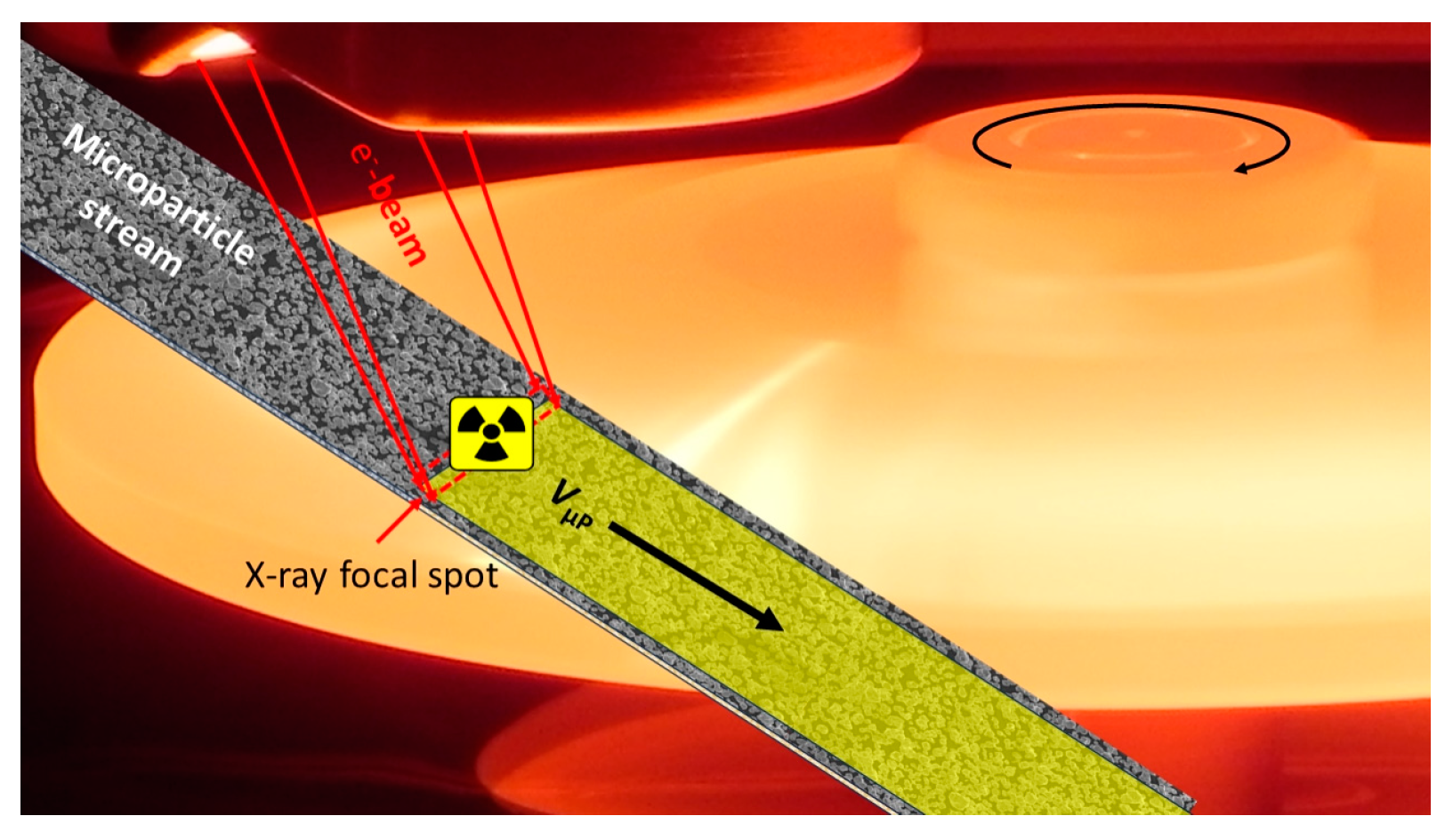
1. Introduction
- Separated µPs do not erode, as rigid targets do;
- Surface heating within a limited erosion temperature range of a dense sintered body is replaced by volume heating up to the melting point [14] or beyond;
- We propose abandoning the classic paradigm that the target is to be conductively coupled with the current source. The target would not then constitute an anode according to the normal definition. It is concluded from our finding that for sufficiently high electron energy, small tungsten µPs backscatter most of the charge that they receive. Electron field emission may contribute as well to balancing the charging state;
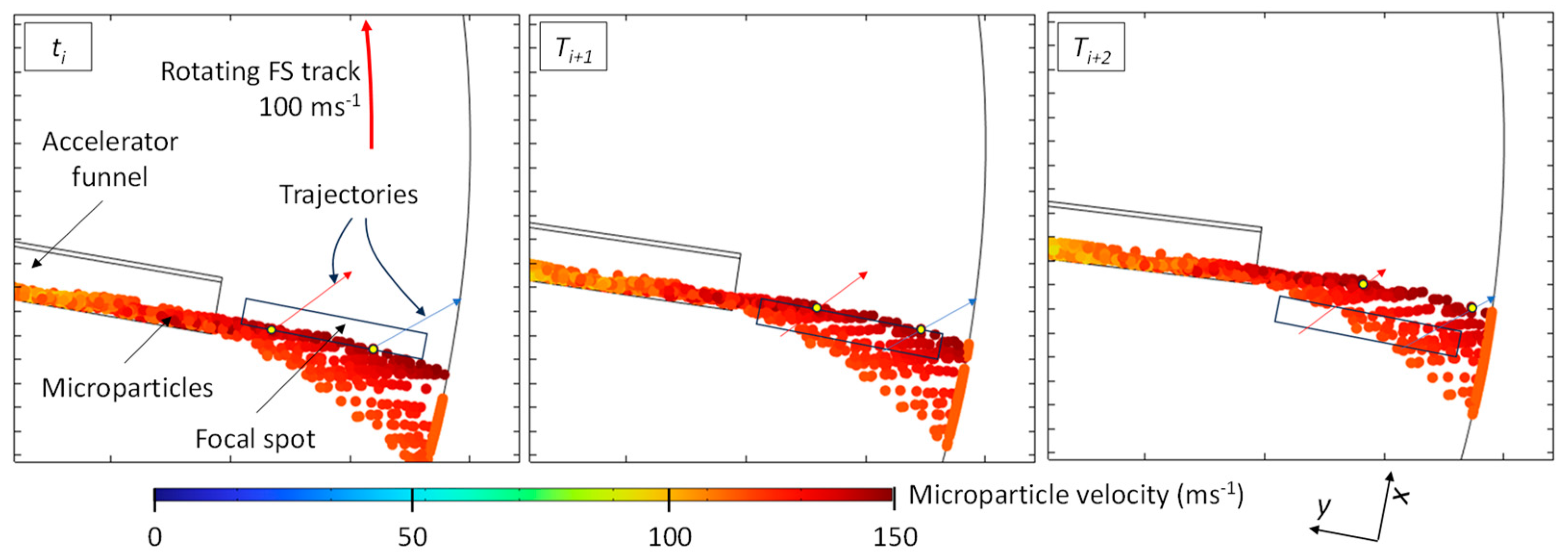
- Microparticles may be accelerated to velocities far exceeding the present FS track velocities of rotors, which are limited to approximately 100 ms−1. The results of initial investigations promise a potential achievable power density gain of up to an order of magnitude for very small FS sizes and tube voltages in the upper CT range and, notably, beyond.
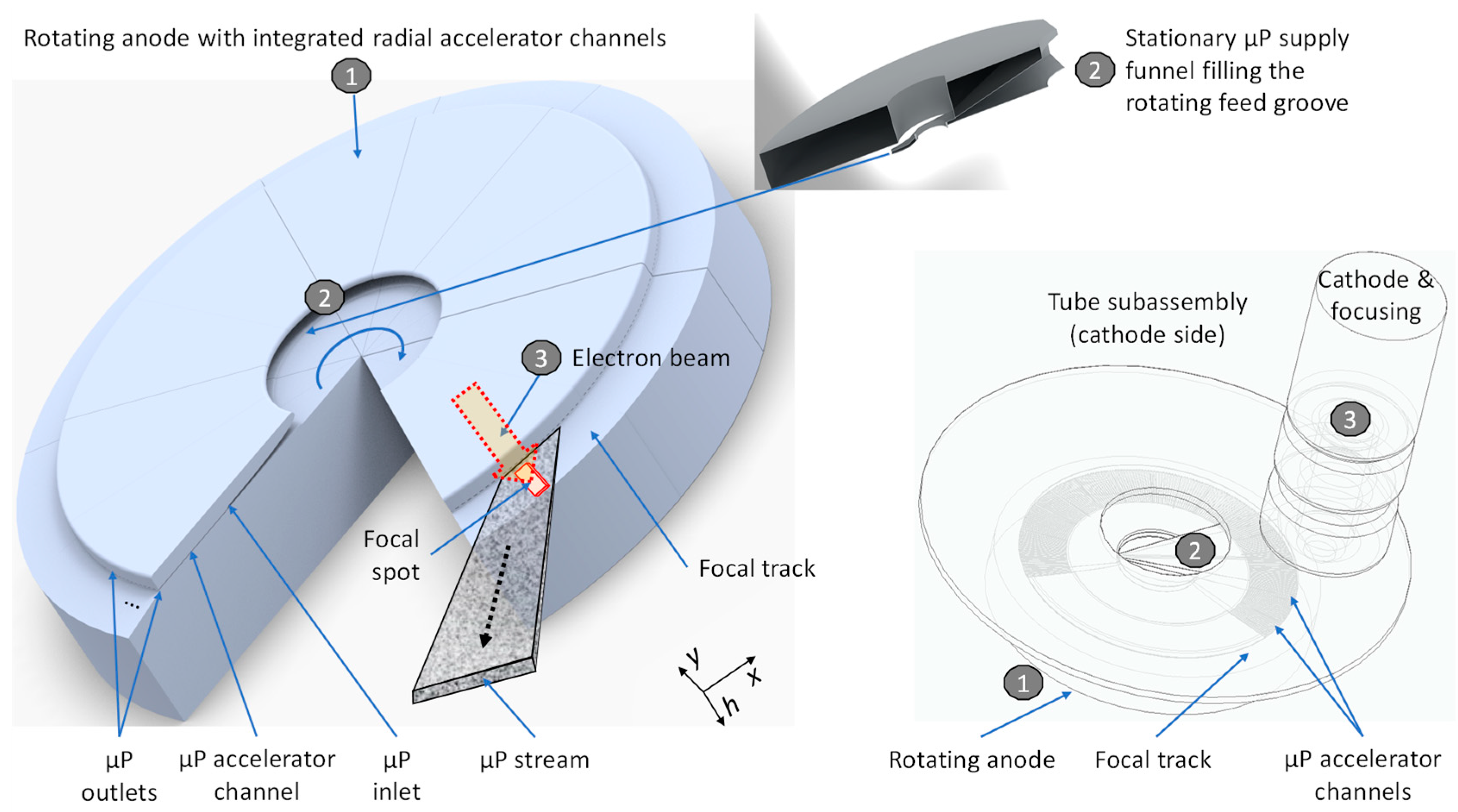
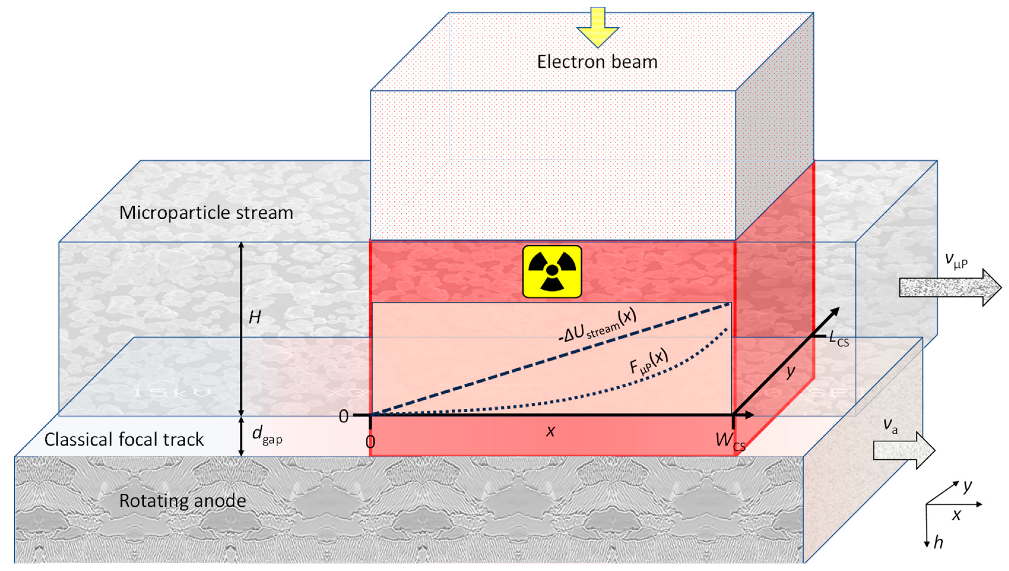
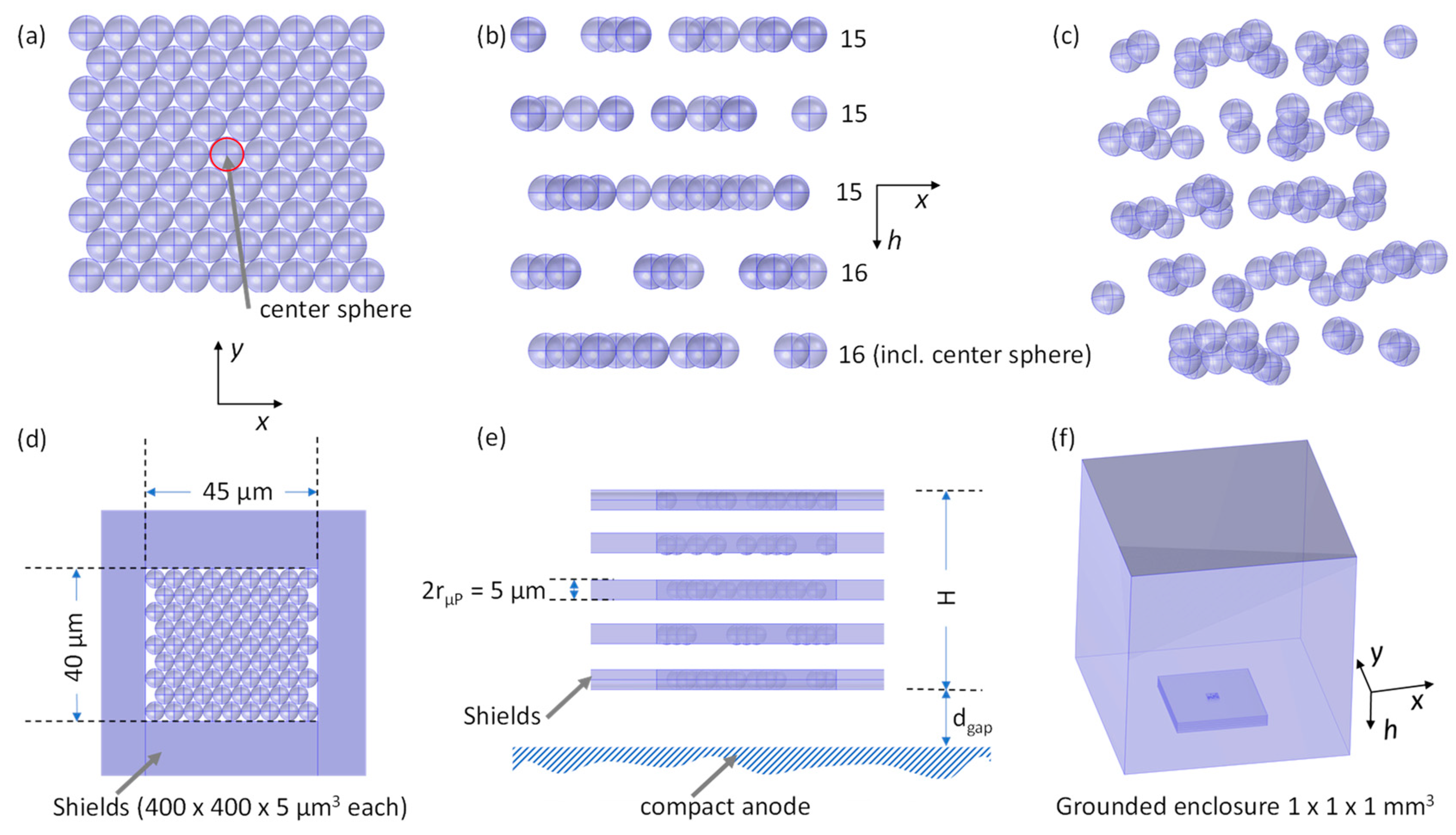
2. Materials and Methods
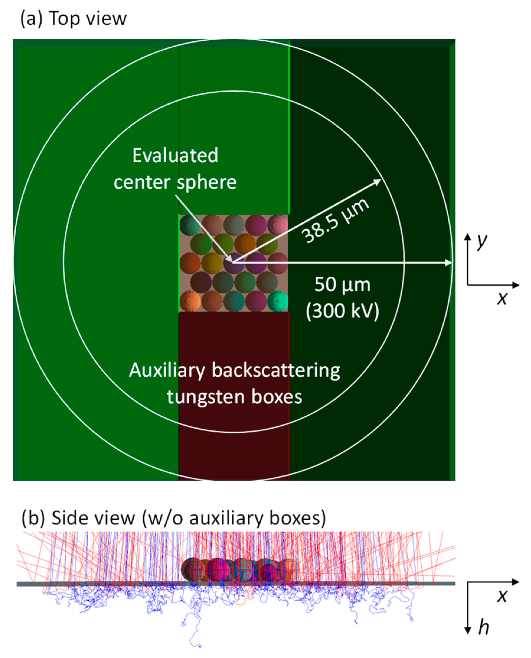
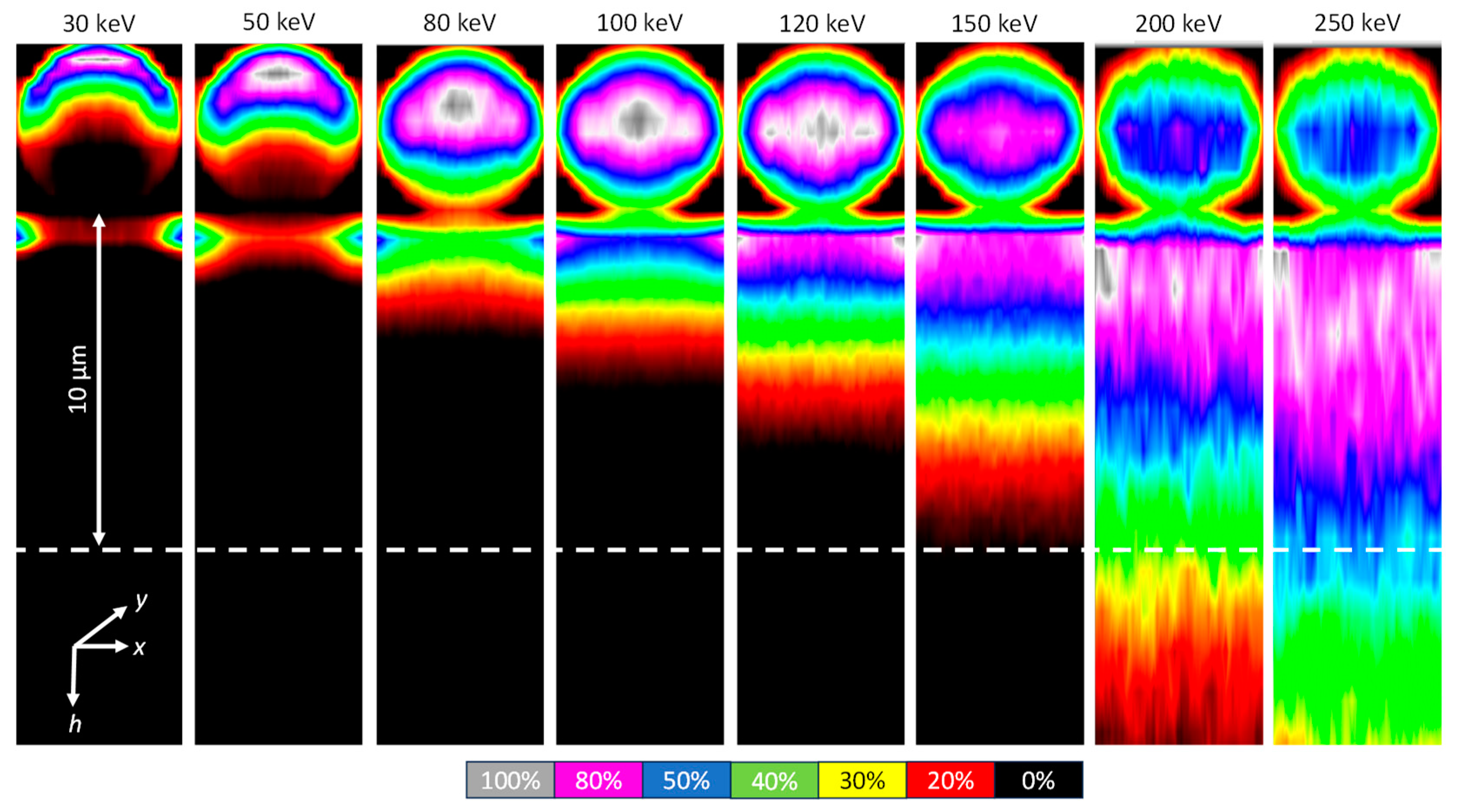
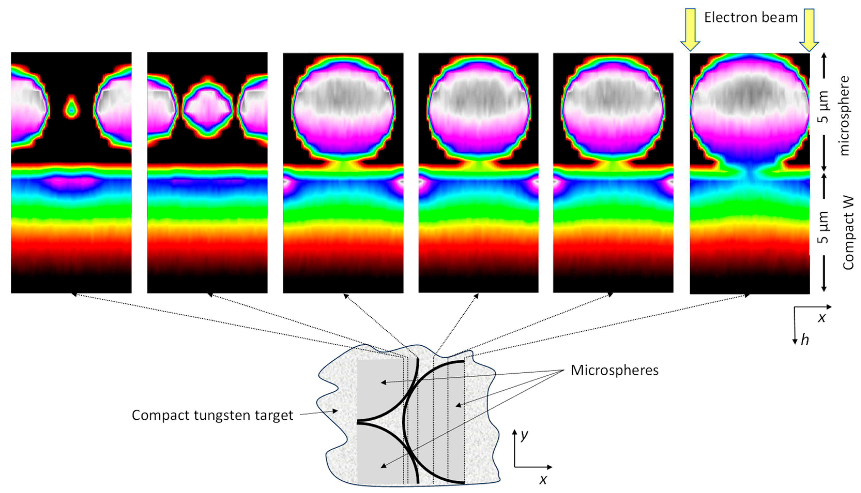
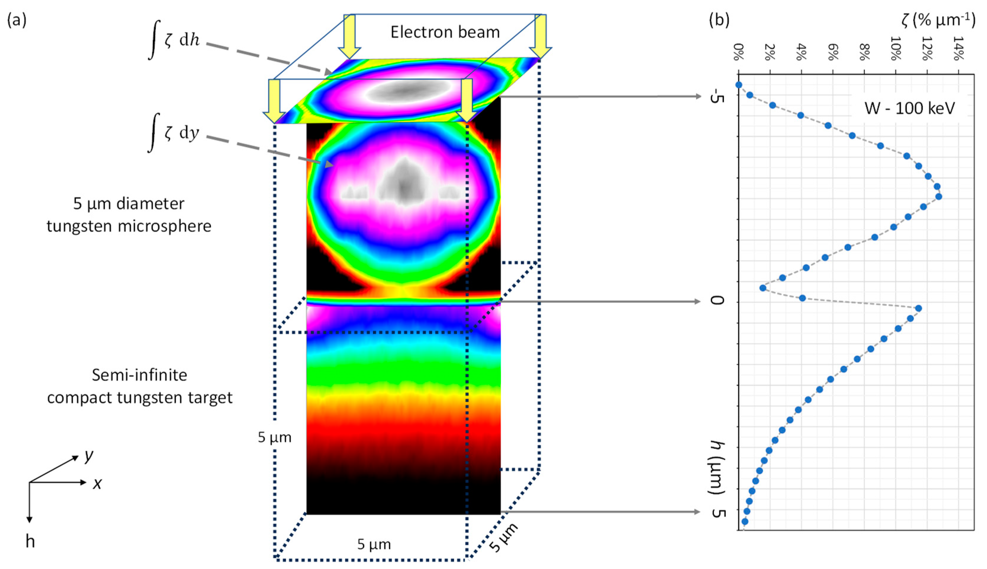
2.1. Depth Distribution of Electronic Power Input
2.2. Simulation of the Electric Potential and Field
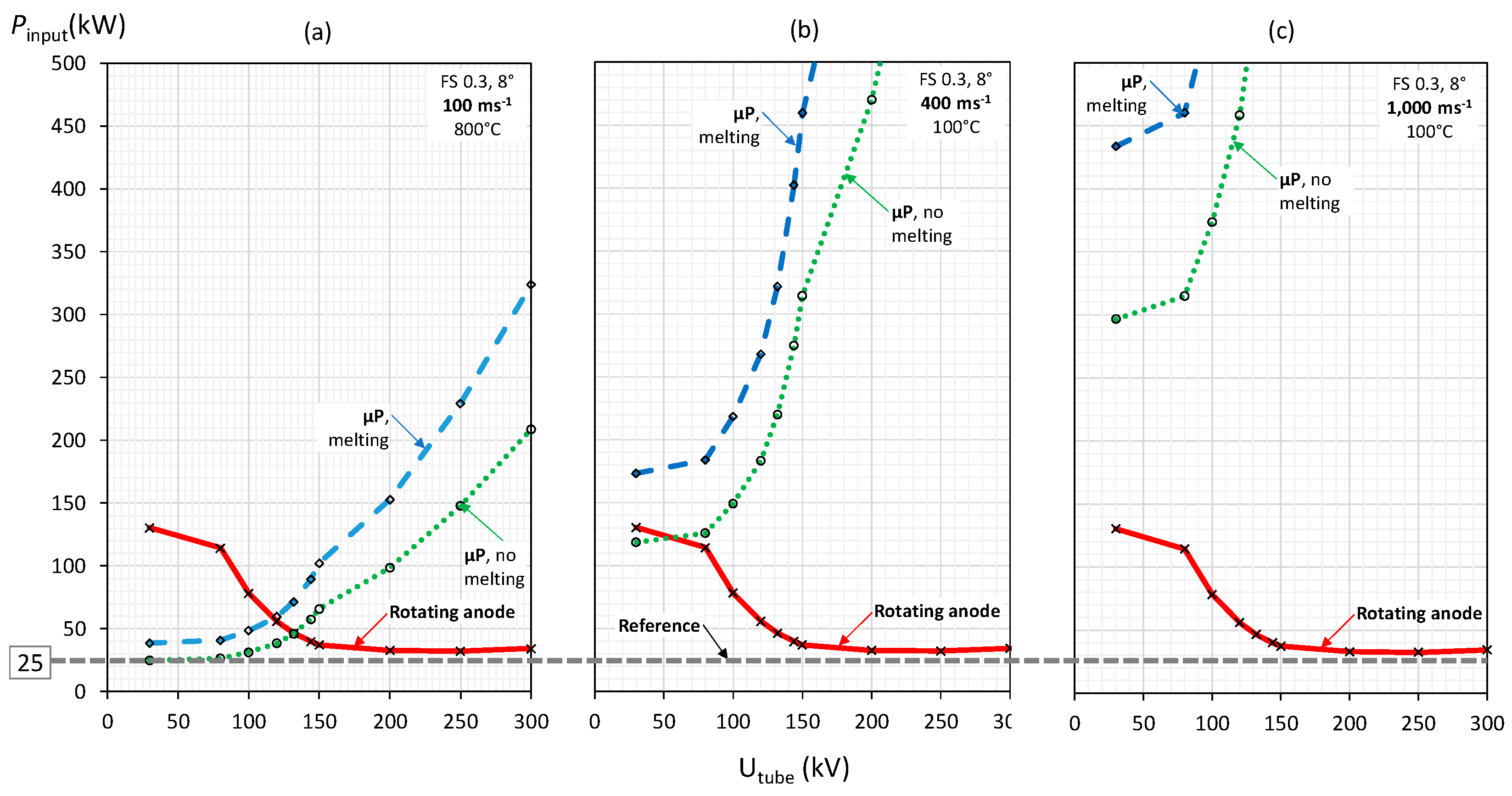
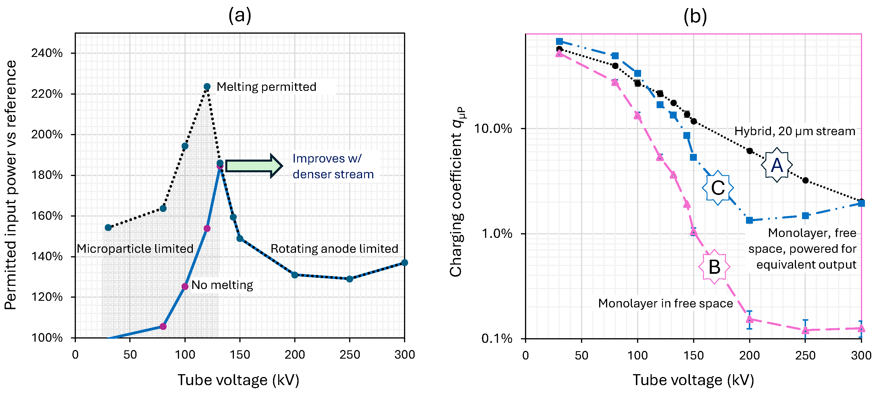
3. Results
3.1. Power Distributions
3.2. Electrical Charging
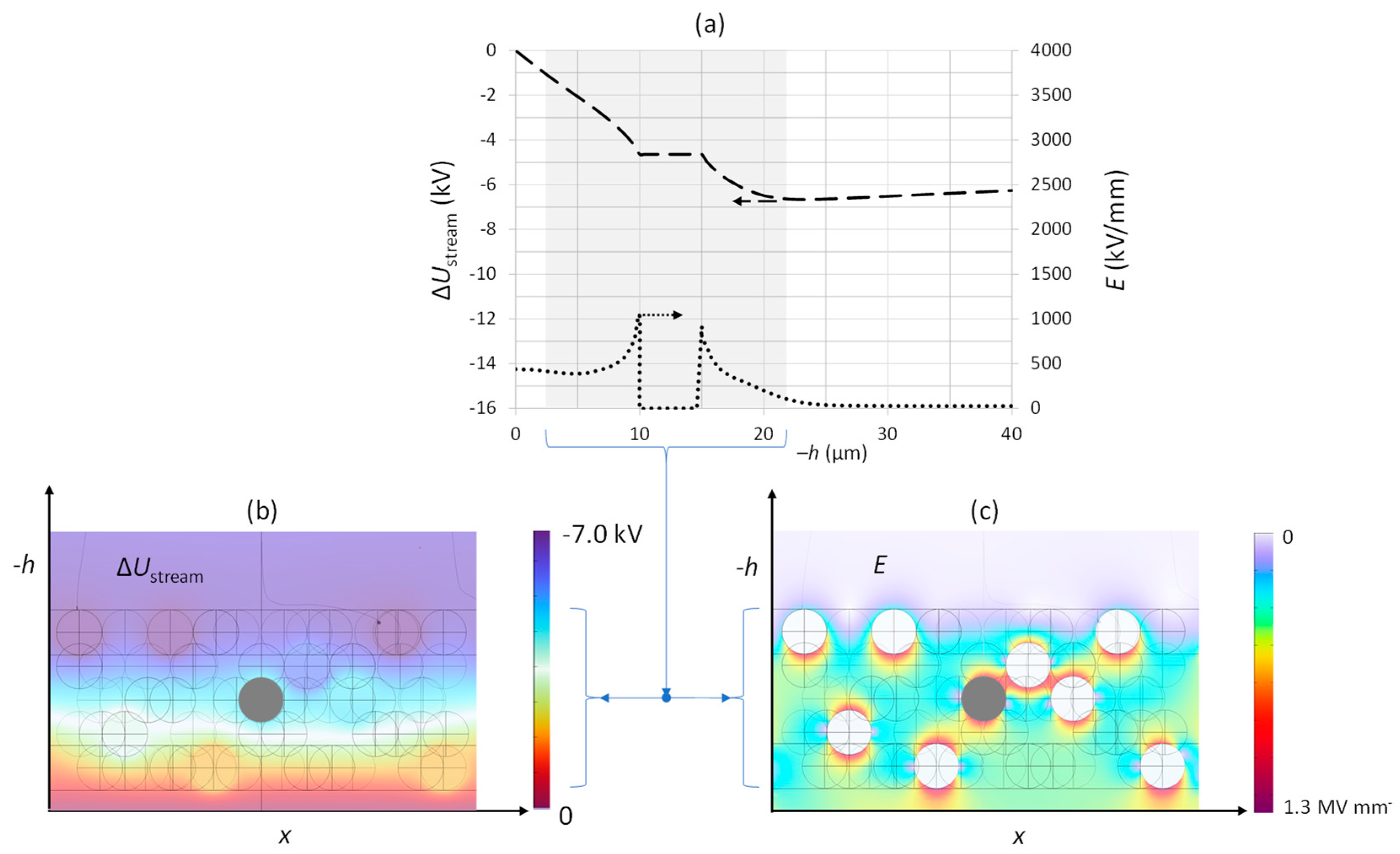
3.3. Electrical Potential of the µP Stream
3.3.1. Discharging by Backscattering Only
3.3.2. Microparticle Stream in Free Space
3.3.3. Impact Charge Equilibration and Charge Reversal
3.3.4. Electron Field Emission Discharge
3.3.5. Other Discharge Mechanisms
4. Discussion
- (a)
- The analysis of the rheologic aspects of µP management;
- (b)
- The use of mechanical µP accelerators;
- (c)
- The use of carbon-reinforced carbon rotors in a hybrid system to minimize the µP charging due to low backscattering (as for other low-z materials, like beryllium) and to maximize the rotor and µP velocity;
- (d)
- The use of magnetic bearings for mechanical µP accelerators that do not necessarily require current contacts;
- (e)
- The means for electrical or magnetic µP (post-) acceleration;
- (f)
- The study of the dynamics of charged µPs in the vicinity of the focal spot;
- (g)
- The introduction of auxiliary means, such as beams of electrons with low energy, to control the charge state of the μPs;
- (h)
- The implementation of mechanical electron windows to remediate the potential difficulties of the high-voltage stability in the cathode region and improve the residual-gas atmosphere in that space;
- (i)
- The usability of high-performance electron emitters by improving the residual-gas atmosphere employing cool rotor bodies, notably when using mechanical electron windows;
- (j)
- The introduction of electrical means to prevent the µPs from entering the cathode region, such as electrically biased grids or apertures to repel charged µPs, including those that may have experienced charge reversal at the electrodes;
- (k)
- The use of liquid-metal-coated surfaces as µP getters;
- (l)
- The use of stationary or rotary mechanical and electrical µP deceleration and cooling means;
- (m)
- The modulation of the µP stream density and velocity during X-ray exposure to minimize the mass flux and to keep the erosion of the hybrid target under control (such as the temperature-dependent µP flux);
- (n)
- The technology of the cooling, capturing, and recycling of the µPs in stationary and revolving X-ray sources in rotary CT gantries employing gradients of centrifugal acceleration or idle periods;
- (o)
- The possibility of hybrid µP designs, stationary anode targets, and liquid-metal jet targets;
- (p)
- The introduction of proximal auxiliary liquid or solid electrodes (such as materials with low backscattering yields) to minimize the electric potential of µP targets;
- (q)
- The realization of multi-energy X-ray sources utilizing µPs of varying sizes that employ the size-dependent backscattering characteristics;
- (r)
- The use of liquid µPs, such as droplets;
- (s)
- The generation of liquid target droplets of a small size employing electrical forces in high electric fields and / or laser or laser plasma recoil interaction;
- (t)
- The evaluation of the cost and ecological aspects (such as omitting rhenium additives or reducing the rotary anode diameter);
- (u)
- Safety aspects.
5. Conclusions
6. Patents
Author Contributions
Funding
Data Availability Statement
Conflicts of Interest
References
- Winter, J.; Dimroth, A.; Roetzer, S.; Zhang, Y.; Krämer, K.; Petrich, C.; Matejcek, C.; Aulenbacher, K.; Zimmermann, M.; Combs, S.E.; et al. Heat management of a compact x-ray source for microbeam radiotherapy and FLASH treatments. Med. Phys. 2022, 49, 3375–3388. [Google Scholar] [CrossRef]
- Bouwers, A.P. An X-ray tube with rotating anode. Physica 10, 125 1930. In X-Ray Research and Development. A Selection of the Publications of the Philips X-Ray Research Laboratory from 1923–1933; Philips: Amsterdam, The Netherlands, 1933; pp. 110–119. [Google Scholar]
- Bouwers, A.P.E.N. X-Ray Tube Having a Rotary Anode. U.S. Patent 2081789, 25 May 1937. [Google Scholar]
- Steidel, J.; Maier, J.; Sawall, S.; Kachelrieß, M. Dose reduction potential in diagnostic single energy CT through patient-specific prefilters and a wider range of tube voltages. Med. Phys. 2022, 49, 93–106. [Google Scholar] [CrossRef] [PubMed]
- Baek, J.; Pineda, A.R.; Pelc, N.J. To bin or not to bin? The effect of CT system limiting resolution on noise and detectability. Phys. Med. Biol. 2013, 58, 1433–1446. [Google Scholar] [CrossRef] [PubMed]
- Eggl, E.; Dierolf, M.; Achterhold, K.; Jud, C.; Günther, B.; Braig, E.; Gleich, B.; Pfeiffer, F. The Munich compact light source: Initial performance measures. J. Synchrotron Radiat. 2016, 23, 1137–1142. [Google Scholar] [CrossRef] [PubMed]
- Behling, R.; Grüner, F. Diagnostic X-ray sources—Present and future. Nucl. Instrum. Methods Phys. Res. A 2018, 878, 50–57. [Google Scholar] [CrossRef]
- Nam, I.; Min, C.-K.; Oh, B.; Kim, G.; Na, D.; Suh, Y.J.; Yang, H.; Cho, M.H.; Kim, C.; Kim, M.-J.; et al. High-brightness self-seeded X-ray free-electron laser covering the 3.5 keV to 14.6 keV range. Nat. Photonics 2021, 15, 435–441. [Google Scholar] [CrossRef]
- Macchi, A.; Pegoraro, F. Lighting up a nest for X-ray emission. Nat. Photonics 2023, 17, 129–130. [Google Scholar] [CrossRef]
- Shou, Y.; Wang, P.; Lee, S.G.; Rhee, Y.J.; Lee, H.W.; Yoon, J.W.; Sung, J.H.; Pan, Z.; Kong, D.; Mei, Z.; et al. Brilliant femtosecond-laser-driven hard X-ray flashes from carbon nanotube plasma. Nat. Photonics 2023, 17, 137–142. [Google Scholar] [CrossRef]
- Hertz, H.; Hemberg, O. Method and Apparatus for Generating X-Ray Radiation. Patent EP1305984B1, 24 November 2010. [Google Scholar]
- Espes, E.; Andersson, T.; Björnsson, F.; Gratorp, C.; Hansson, B.A.M.; Hemberg, O.; Johansson, G.; Kronstedt, J.; Otendal, M.; Tuohimaa, T.; et al. Liquid-metal-jet x-ray tube technology and tomography applications. SPIE Opt. Eng. Appl. 2014, 9212, 92120J. [Google Scholar] [CrossRef]
- Behling, R.; Danielsson, M. Particle Based X-Ray Source. U.S. Patent US11882642B2, 23 January 2024. [Google Scholar]
- Whitaker, S. Thermal Analysis of Solid, Rotating, X-Ray Tube Anodes: New Results And A Comparison with Prior Studies; Dwyer, S.J., III, Schneider, R.H., Eds.; SPIE: Bellingham, WA, USA, 1984; pp. 285–293. [Google Scholar] [CrossRef]
- Demers, H.; Poirier-Demers, N.; Couture, A.R.; Joly, D.; Guilmain, M.; de Jonge, N.; Drouin, D. Three-dimensional electron microscopy simulation with the CASINO Monte Carlo software. Scanning 2011, 33, 135–146. [Google Scholar] [CrossRef] [PubMed]
- Behling, R. Modern Diagnostic X-ray Sources, 2nd ed.; CRC Press: Boca Raton, FL, USA, 2021. [Google Scholar] [CrossRef]
- Comsol, A.B. COMSOL Multiphysics® v. 6.2. Stockholm, Sweden. Available online: www.comsol.com (accessed on 4 July 2023).
- Tolias, P. Analytical expressions for thermophysical properties of solid and liquid tungsten relevant for fusion applications. Nucl. Mater. Energy 2017, 13, 42–57. [Google Scholar] [CrossRef]
- Muller, A. A spinning target X-ray generator and its input limit. Proc. R. Soc. Lond. A 1929, 125, 507–516. [Google Scholar] [CrossRef]
- Oosterkamp, W.J. The heat dissipation in the anode of an X-ray tube—Part II—Loads of short duration applied to rotating anodes. Philips Res. Rep. 1948, 3, 161–173. [Google Scholar]
- Tolias, P. On electron backscattering from dust grains in fusion plasmas. Plasma Phys. Control. Fusion 2014, 56, 045003. [Google Scholar] [CrossRef]
- Stronge, W.J. Impact Mechanics, 1st ed.; Cambridge University Press: Cambridge, UK, 2000. [Google Scholar] [CrossRef]
- Murphy, E.L.; Good, R.H. Thermionic Emission, Field Emission, and the Transition Region. Phys. Rev. 1956, 102, 1464–1473. [Google Scholar] [CrossRef]
- Latham, R. (Ed.) High Voltage Vacuum Insulation; Academic Press: New York, NY, USA, 1995. [Google Scholar]
- Ratynskaia, S.; Tolias, P.; Shalpegin, A.; Vignitchouk, L.; De Angeli, M.; Bykov, I.; Bystrov, K.; Bardin, S.; Brochard, F.; Ripamonti, D.; et al. Elastic–plastic adhesive impacts of tungsten dust with metal surfaces in plasma environments. J. Nucl. Mater. 2015, 463, 877–880. [Google Scholar] [CrossRef]
- Riva, G.; Tolias, P.; Ratynskaia, S.; Daminelli, G.; Donde, R.; De Angeli, M.; Vassallo, E.; Pedroni, M. Adhesion measurements for tungsten dust deposited on tungsten surfaces. Nucl. Mater. Energy 2017, 12, 593–598. [Google Scholar] [CrossRef]
- Modinos, A. Field, Thermionic, and Secondary Electron Emission Spectroscopy, 1st ed.; Springer Science + Business Media: New York, NY, USA, 1984. [Google Scholar] [CrossRef]

| Utube (kV) | SµP | Sanode | 1 − ηe (hybrid) |
|---|---|---|---|
| 30 | 56.6% | 11.9% | 68.5% |
| 80 | 53.3% | 13.7% | 65.7% |
| 100 | 44.9% | 20.8% | 64.8% |
| 120 | 36.6% | 28.2% | 64.9% |
| 150 | 21.3% | 42.6% | 64.0% |
| 200 | 14.3% | 48.9% | 63.2% |
| 250 | 9.5% | 50.2% | 59.7% |
| 300 | 6.7% | 47.7% | 54.4% |
Disclaimer/Publisher’s Note: The statements, opinions and data contained in all publications are solely those of the individual author(s) and contributor(s) and not of MDPI and/or the editor(s). MDPI and/or the editor(s) disclaim responsibility for any injury to people or property resulting from any ideas, methods, instructions or products referred to in the content. |
© 2024 by the authors. Licensee MDPI, Basel, Switzerland. This article is an open access article distributed under the terms and conditions of the Creative Commons Attribution (CC BY) license (https://creativecommons.org/licenses/by/4.0/).
Share and Cite
Behling, R.; Hulme, C.; Tolias, P.; Poludniowski, G.; Danielsson, M. Microparticle Hybrid Target Simulation for keV X-ray Sources. Instruments 2024, 8, 32. https://doi.org/10.3390/instruments8020032
Behling R, Hulme C, Tolias P, Poludniowski G, Danielsson M. Microparticle Hybrid Target Simulation for keV X-ray Sources. Instruments. 2024; 8(2):32. https://doi.org/10.3390/instruments8020032
Chicago/Turabian StyleBehling, Rolf, Christopher Hulme, Panagiotis Tolias, Gavin Poludniowski, and Mats Danielsson. 2024. "Microparticle Hybrid Target Simulation for keV X-ray Sources" Instruments 8, no. 2: 32. https://doi.org/10.3390/instruments8020032
APA StyleBehling, R., Hulme, C., Tolias, P., Poludniowski, G., & Danielsson, M. (2024). Microparticle Hybrid Target Simulation for keV X-ray Sources. Instruments, 8(2), 32. https://doi.org/10.3390/instruments8020032